KR20160051069A - A separator for a secondary battery - Google Patents
A separator for a secondary battery Download PDFInfo
- Publication number
- KR20160051069A KR20160051069A KR1020140150463A KR20140150463A KR20160051069A KR 20160051069 A KR20160051069 A KR 20160051069A KR 1020140150463 A KR1020140150463 A KR 1020140150463A KR 20140150463 A KR20140150463 A KR 20140150463A KR 20160051069 A KR20160051069 A KR 20160051069A
- Authority
- KR
- South Korea
- Prior art keywords
- stretching ratio
- film
- separator
- film layers
- layer
- Prior art date
- Legal status (The legal status is an assumption and is not a legal conclusion. Google has not performed a legal analysis and makes no representation as to the accuracy of the status listed.)
- Granted
Links
Images

Classifications
-
- H—ELECTRICITY
- H01—ELECTRIC ELEMENTS
- H01M—PROCESSES OR MEANS, e.g. BATTERIES, FOR THE DIRECT CONVERSION OF CHEMICAL ENERGY INTO ELECTRICAL ENERGY
- H01M50/00—Constructional details or processes of manufacture of the non-active parts of electrochemical cells other than fuel cells, e.g. hybrid cells
- H01M50/40—Separators; Membranes; Diaphragms; Spacing elements inside cells
- H01M50/409—Separators, membranes or diaphragms characterised by the material
- H01M50/449—Separators, membranes or diaphragms characterised by the material having a layered structure
-
- H—ELECTRICITY
- H01—ELECTRIC ELEMENTS
- H01M—PROCESSES OR MEANS, e.g. BATTERIES, FOR THE DIRECT CONVERSION OF CHEMICAL ENERGY INTO ELECTRICAL ENERGY
- H01M50/00—Constructional details or processes of manufacture of the non-active parts of electrochemical cells other than fuel cells, e.g. hybrid cells
- H01M50/40—Separators; Membranes; Diaphragms; Spacing elements inside cells
- H01M50/409—Separators, membranes or diaphragms characterised by the material
- H01M50/411—Organic material
- H01M50/414—Synthetic resins, e.g. thermoplastics or thermosetting resins
- H01M50/417—Polyolefins
-
- H—ELECTRICITY
- H01—ELECTRIC ELEMENTS
- H01M—PROCESSES OR MEANS, e.g. BATTERIES, FOR THE DIRECT CONVERSION OF CHEMICAL ENERGY INTO ELECTRICAL ENERGY
- H01M50/00—Constructional details or processes of manufacture of the non-active parts of electrochemical cells other than fuel cells, e.g. hybrid cells
- H01M50/40—Separators; Membranes; Diaphragms; Spacing elements inside cells
- H01M50/409—Separators, membranes or diaphragms characterised by the material
- H01M50/431—Inorganic material
- H01M50/434—Ceramics
-
- H—ELECTRICITY
- H01—ELECTRIC ELEMENTS
- H01M—PROCESSES OR MEANS, e.g. BATTERIES, FOR THE DIRECT CONVERSION OF CHEMICAL ENERGY INTO ELECTRICAL ENERGY
- H01M50/00—Constructional details or processes of manufacture of the non-active parts of electrochemical cells other than fuel cells, e.g. hybrid cells
- H01M50/40—Separators; Membranes; Diaphragms; Spacing elements inside cells
- H01M50/409—Separators, membranes or diaphragms characterised by the material
- H01M50/443—Particulate material
-
- H—ELECTRICITY
- H01—ELECTRIC ELEMENTS
- H01M—PROCESSES OR MEANS, e.g. BATTERIES, FOR THE DIRECT CONVERSION OF CHEMICAL ENERGY INTO ELECTRICAL ENERGY
- H01M50/00—Constructional details or processes of manufacture of the non-active parts of electrochemical cells other than fuel cells, e.g. hybrid cells
- H01M50/40—Separators; Membranes; Diaphragms; Spacing elements inside cells
- H01M50/409—Separators, membranes or diaphragms characterised by the material
- H01M50/446—Composite material consisting of a mixture of organic and inorganic materials
-
- H—ELECTRICITY
- H01—ELECTRIC ELEMENTS
- H01M—PROCESSES OR MEANS, e.g. BATTERIES, FOR THE DIRECT CONVERSION OF CHEMICAL ENERGY INTO ELECTRICAL ENERGY
- H01M50/00—Constructional details or processes of manufacture of the non-active parts of electrochemical cells other than fuel cells, e.g. hybrid cells
- H01M50/40—Separators; Membranes; Diaphragms; Spacing elements inside cells
- H01M50/46—Separators, membranes or diaphragms characterised by their combination with electrodes
-
- H—ELECTRICITY
- H01—ELECTRIC ELEMENTS
- H01M—PROCESSES OR MEANS, e.g. BATTERIES, FOR THE DIRECT CONVERSION OF CHEMICAL ENERGY INTO ELECTRICAL ENERGY
- H01M50/00—Constructional details or processes of manufacture of the non-active parts of electrochemical cells other than fuel cells, e.g. hybrid cells
- H01M50/40—Separators; Membranes; Diaphragms; Spacing elements inside cells
- H01M50/463—Separators, membranes or diaphragms characterised by their shape
-
- H—ELECTRICITY
- H01—ELECTRIC ELEMENTS
- H01M—PROCESSES OR MEANS, e.g. BATTERIES, FOR THE DIRECT CONVERSION OF CHEMICAL ENERGY INTO ELECTRICAL ENERGY
- H01M50/00—Constructional details or processes of manufacture of the non-active parts of electrochemical cells other than fuel cells, e.g. hybrid cells
- H01M50/40—Separators; Membranes; Diaphragms; Spacing elements inside cells
- H01M50/489—Separators, membranes, diaphragms or spacing elements inside the cells, characterised by their physical properties, e.g. swelling degree, hydrophilicity or shut down properties
-
- Y—GENERAL TAGGING OF NEW TECHNOLOGICAL DEVELOPMENTS; GENERAL TAGGING OF CROSS-SECTIONAL TECHNOLOGIES SPANNING OVER SEVERAL SECTIONS OF THE IPC; TECHNICAL SUBJECTS COVERED BY FORMER USPC CROSS-REFERENCE ART COLLECTIONS [XRACs] AND DIGESTS
- Y02—TECHNOLOGIES OR APPLICATIONS FOR MITIGATION OR ADAPTATION AGAINST CLIMATE CHANGE
- Y02E—REDUCTION OF GREENHOUSE GAS [GHG] EMISSIONS, RELATED TO ENERGY GENERATION, TRANSMISSION OR DISTRIBUTION
- Y02E60/00—Enabling technologies; Technologies with a potential or indirect contribution to GHG emissions mitigation
- Y02E60/10—Energy storage using batteries
-
- Y—GENERAL TAGGING OF NEW TECHNOLOGICAL DEVELOPMENTS; GENERAL TAGGING OF CROSS-SECTIONAL TECHNOLOGIES SPANNING OVER SEVERAL SECTIONS OF THE IPC; TECHNICAL SUBJECTS COVERED BY FORMER USPC CROSS-REFERENCE ART COLLECTIONS [XRACs] AND DIGESTS
- Y02—TECHNOLOGIES OR APPLICATIONS FOR MITIGATION OR ADAPTATION AGAINST CLIMATE CHANGE
- Y02E—REDUCTION OF GREENHOUSE GAS [GHG] EMISSIONS, RELATED TO ENERGY GENERATION, TRANSMISSION OR DISTRIBUTION
- Y02E60/00—Enabling technologies; Technologies with a potential or indirect contribution to GHG emissions mitigation
- Y02E60/13—Energy storage using capacitors
-
- Y—GENERAL TAGGING OF NEW TECHNOLOGICAL DEVELOPMENTS; GENERAL TAGGING OF CROSS-SECTIONAL TECHNOLOGIES SPANNING OVER SEVERAL SECTIONS OF THE IPC; TECHNICAL SUBJECTS COVERED BY FORMER USPC CROSS-REFERENCE ART COLLECTIONS [XRACs] AND DIGESTS
- Y02—TECHNOLOGIES OR APPLICATIONS FOR MITIGATION OR ADAPTATION AGAINST CLIMATE CHANGE
- Y02E—REDUCTION OF GREENHOUSE GAS [GHG] EMISSIONS, RELATED TO ENERGY GENERATION, TRANSMISSION OR DISTRIBUTION
- Y02E60/00—Enabling technologies; Technologies with a potential or indirect contribution to GHG emissions mitigation
- Y02E60/30—Hydrogen technology
- Y02E60/50—Fuel cells
Landscapes
- Chemical & Material Sciences (AREA)
- Chemical Kinetics & Catalysis (AREA)
- Electrochemistry (AREA)
- General Chemical & Material Sciences (AREA)
- Engineering & Computer Science (AREA)
- Inorganic Chemistry (AREA)
- Composite Materials (AREA)
- Materials Engineering (AREA)
- Ceramic Engineering (AREA)
- Cell Separators (AREA)
Abstract
본 발명은 이차 전지의 분리막에 대한 것이다. 더욱 상세하게는 고온 조건에서 분리막의 수축율이 개선되어 안전성이 우수한 이차 전지의 분리막에 대한 것이다. 본 발명에 따른 분리막은 고온 조건에서도 분리막의 수축율이 낮으며, 내열성 및 치수안정성이 우수하다. 따라서 본 발명에 따른 분리막을 개재하여 제조된 전지의 고온 안전성을 향상시키는 효과가 있다. The present invention relates to a separation membrane of a secondary battery. More particularly, the present invention relates to a separation membrane of a secondary battery having improved shrinkage ratio of a separation membrane under high temperature conditions and excellent safety. The separator according to the present invention has a low shrinkage ratio of the separator even at a high temperature, and is excellent in heat resistance and dimensional stability. Therefore, there is an effect of improving the high-temperature safety of the battery manufactured through the separator according to the present invention.
Description
본 발명은 이차 전지의 분리막에 대한 것이다. 더욱 상세하게는 고온 조건에서 분리막의 수축율이 개선되어 안전성이 우수한 이차 전지의 분리막에 대한 것이다.
The present invention relates to a separation membrane of a secondary battery. More particularly, the present invention relates to a separation membrane of a secondary battery having improved shrinkage ratio of a separation membrane under high temperature conditions and excellent safety.
폴리올레핀계 미세다공막(microporous film)은 그 화학적 안정성과 우수한 물성으로 각종 전지용 분리막 (battery separator), 분리용 필터 및 미세여과용 분리막(membrane) 등으로 널리 이용되고 있다. Polyolefin microporous films are widely used for various battery separators, separating filters, and microfiltration membranes due to their chemical stability and excellent physical properties.
리튬이온 이차전지는 에너지 밀도가 매우 높은 우수한 전지이나, 단락 발생시 폭발의 위험성이 존재하여, 사용 되는 분리막은 높은 품질 수준에 대한 요구와 함께 품질 안정성도 크게 요구되고 있다. 최근에는 하이브리드 자동차용 전지등과 같이 리튬이온 이차전지의 고용량, 고출력 추세에 맞추어 기존 습식제품의 품질 안정성에 더하여 분리막의 열적 안정성이 더욱 크게 요구되고 있다. 분리막의 열안정성이 떨어지면 전지 과열에 따른 분리막의 용융파단에 의한 폭발의 위험성이 커지게 되기 때문이다.The lithium ion secondary battery is an excellent battery having a very high energy density. However, there is a risk of explosion when a short circuit occurs. Therefore, a separation membrane to be used requires a high quality level as well as quality stability. In recent years, in accordance with the high capacity and high output trend of lithium ion secondary batteries such as batteries for hybrid vehicles, the thermal stability of the separator has been demanded in addition to the quality stability of existing wet products. If the thermal stability of the separator is lowered, the risk of explosion due to melt breakage of the separator due to overheating of the battery is increased.
전지내에서 분리막의 열적 안정성은 셧-다운(shut-down) 온도와 용융파단온도에 의해 결정되는데, 전지의 안정성을 위해서는 셧-다운 온도는 낮고 용융파단 온도는 높은 것이 좋다. 특히 용융파단온도는 전지의 폭발을 유발할 수도 있는 상황에서 전류를 계속 차단하여 줄 수 있는 온도로 전지의 안정성에 가장 밀접한 관계를 가지고 있다.The thermal stability of the separator in the cell is determined by the shut-down temperature and the melt fracture temperature. For the stability of the battery, the shut-down temperature is low and the melt fracture temperature is high. In particular, the melt fracture temperature is a temperature at which the current can be continuously cut off in a situation where the explosion of the battery may be caused, which is most closely related to the stability of the battery.
분리막의 열 안정성을 향상시키기 위한 노력은 크게 세 방향으로 전개되어 왔다. 무기물 혹은 내열성이 있는 수지를 기존 폴리에틸렌에 첨가하여 분리막의 내열성을 높이는 방법과 내열성이 있는 물질을 표면에 코팅하는 방법 그리고 내열성이 있는 층이 존재하는 다층 분리막을 만드는 방법이다. Efforts to improve the thermal stability of the separator have been developed in three directions. A method of increasing the heat resistance of a separator by adding an inorganic or heat resistant resin to a conventional polyethylene, a method of coating a heat resistant material on the surface, and a method of making a multilayer separator having a heat resistant layer.
미국 특허 제6,949,315 에는 초고분자량 폴리에틸렌에 5-15중량%의 티타늄옥사이드 등의 무기물을 혼련하여 분 리막의 열안정성을 향상시킨 필름이 소개되어 있다. 그러나 이 방법은 무기물 첨가에 따른 열안정성 향상 효과는 있으나 무기물 투입에 따른 혼련성 저하 및 혼련성 저하에 따른 연신시 핀홀 발생 및 품질 불균일 등의 문제가 발생하기 쉽고, 무기물과 고분자수지 계면의 친화력 (Compatibility) 부족으로 충격강도 등의 필름 물성 저하가 발생하게 된다. 이러한 단점은 무기물을 사용하는 분리막에는 필연적으로 나타날 수밖에 없는 것이다.U.S. Patent No. 6,949,315 discloses a film in which an ultrahigh molecular weight polyethylene is kneaded with an inorganic substance such as titanium oxide in an amount of 5-15% by weight to improve the thermal stability of the separation membrane. However, this method has the effect of improving the thermal stability according to the addition of the inorganic substance, but the problems such as the lowering of the kneading property due to the addition of the inorganic substance and the lowering of the kneading property are liable to occur, Compatibility is insufficient, resulting in deterioration of film properties such as impact strength. These disadvantages are inevitable for separators using inorganic materials.
무기물 대신 내열성이 우수한 수지를 혼련하여 제조되는 분리막은 미국 특허 제5,641,565호에 나타나 있다. 이 기술은 폴리에틸렌에 5-45 중량%의 폴리프로필렌을 혼합한 수지혼합물에 30-75 중량%의 유기 액상 화합물과 10-50 중량%의 무기물을 혼합한 후 유기 액상 화합물과 무기물을 추출하여 분리막을 만드는 기술이다. 이 기술에서는 비록 무기물을 추출해 내기는 하나 상기한 무기물 혼련시의 문제점을 그대로 가지게 되고, 상기 특허 자체에서 언급한 바와 같이 폴리에틸렌과 혼련성이 없는 폴리프로필렌의 첨가에 따른 물성 저하가 발생하게 된다. 또한 이 방법은 사용된 무기물을 추출, 제거하기 위한 공정이 추가되어 공정이 복잡해지는 단점이 있으며 충분한 내열 효과를 얻기 위해서는 비교적 많은 양의 폴리프로필렌을 필요로 하며 이 경우 분리막의 물성은 더욱 떨어지게 된다.A separation membrane prepared by kneading a resin having excellent heat resistance instead of an inorganic material is disclosed in U.S. Patent No. 5,641,565. The technique involves mixing 30-75% by weight of an organic liquid compound and 10-50% by weight of an inorganic material in a resin mixture obtained by mixing 5-45% by weight of polypropylene with polyethylene, separating the organic liquid compound and the inorganic material, Technology. Although this technique extracts minerals, it has a problem in the above-mentioned inorganic material kneading, and as mentioned in the above-mentioned patent, the physical properties are lowered by the addition of polypropylene which is not kneaded with polyethylene. In addition, this method has a disadvantage in that the process is complicated by adding a process for extracting and removing the used minerals, and a relatively large amount of polypropylene is required in order to obtain a sufficient heat-resistant effect.
내열성이 있는 물질을 미세다공막 표면에 코팅하는 방법은 US 2006-0055075A1 에 나타나 있다. 그러나 코팅 방 식은 코팅층의 투과도를 높이는데 한계가 있어 전체 필름의 투과도가 낮아지고 코팅층과 미다공막 필름 사이의 웨팅성 저하로 품질 불균일이 발생할 소지가 높다.A method of coating a heat-resistant material on the surface of a microporous membrane is disclosed in US 2006-0055075A1. However, the coating method has a limitation in increasing the transmittance of the coating layer, so that the transmittance of the entire film is lowered and the wettability between the coating layer and the microporous membrane film is likely to cause quality irregularities.
분리막의 열안정성을 증가시키기 위해 다층 분리막을 만드는 방법은 라미네이션을 이용하는 것이다. 미국 특허 제5,691,077호에는 닫힘특성이 우수한 (녹는 온도가 낮은) 폴리에틸렌에 용융파단온도가 높은 (녹는 온도가 높은) 폴리프로필렌 수지를 라미네이션하여 3층구조의 분리막을 만드는 방법이 나타나있다. 이 분리막은 열적 특성에서는 우수하나 저온 건식법에 의한 원단 필름 제조 과정에서의 연신불균일, 핀홀발생, 두께 편차 증가 등의 단점과 함께 별도 공정에서 진행되는 라미네이션 공정 추가로 인한 생산성 저하 문제이외에도 라미네이션 불량에서 오는 디라미네이션 문제도 있어 널리 사용되지 못하고 있다. 이 방법은 우수한 내열성 에도 불구하고 이차전지용 분리막에서 꼭 필요한 강성, 투과성, 품질균일성 및 생산성이 떨어지는 문제점을 가 지고 있다.Lamination is used to make a multilayer separator to increase the thermal stability of the separator. U.S. Patent No. 5,691,077 discloses a method for making a three-layered separator by laminating a polypropylene resin having a high melt breaking temperature (high melting temperature) to polyethylene having excellent closure characteristics (low melting temperature). This separator is excellent in thermal properties, but it has disadvantages such as non-uniformity in drawing, pinhole occurrence and thickness variation in the manufacturing process of a fabric film by a low temperature drying method, as well as a problem of productivity deterioration due to addition of a lamination process, There is also a problem of delamination and it is not widely used. This method has a problem that the rigidity, permeability, quality uniformity and productivity required for the secondary battery separator are inferior despite the excellent heat resistance.
일본공개특허 2002-321323 과 국제공개특허 WO2004/089627 에는 습식법으로 제조되는 폴리에틸렌 미다공막층을 주(main) 층으로하고, 역시 습식법으로 제조되는 폴리에틸렌과 폴리프로필렌이 혼합된 층을 표면층으로 하는 다층 분리막이 소개되어있다. 이들 분리막은 습식공정으로 제조되어 품질 안정성은 우수할 수 있으나 폴리프로필렌 수지의 내열성 이상의 내열성을 가지는 데는 한계가 있다. 또한 다층의 분리막을 모두 습식법으로 제조하므로 제조공정이 까다로워지는 단점도 있다. 국제공개특허 WO2006/038532 에는 무기입자를 포함하는 다층 습식 분리막이 소개되어있는데, 이 분리막 역시 상기 언급한데로 다층의 분리막을 모두 습식으로 제조하는데 따른 까다로운 혼련공정과 표면층에도 필름생산과정에서 반드시 추출해야만하는 다일루언트를 50% 이상 포함하여 제품을 생산하는데 따른 낮은 물성 향상 효과 (다일루언트가 포함된 연화된 상태에서 연신을 수행하므로 연신 효과가 줄어듬) 를 보이게 된다.Japanese Patent Application Laid-Open No. 2002-321323 and International Patent Publication No. WO2004 / 089627 disclose a multilayer separator wherein a polyethylene microporous membrane layer produced by a wet method is used as a main layer and a layer in which polyethylene and polypropylene, Is introduced. These separation membranes can be manufactured by a wet process and have excellent quality stability, but they have limitations in that they have heat resistance more than heat resistance of polypropylene resin. In addition, since the multi-layer separator is manufactured by the wet process, the manufacturing process becomes complicated. International Patent Publication No. WO2006 / 038532 discloses a multi-layered wet separator comprising inorganic particles. As mentioned above, this separator also has to be extracted in the process of producing the film to the surface layer and the hard kneading process required for producing all the multi- (50% or more) of the diluent, and the low physical property improvement effect of the production of the product (the stretching effect is reduced due to the stretching in the softened state including the diluent).
이차전지용 분리막의 필수적인 특성은 강성, 투과성 및 품질 균일성이며 최근에는 추가적으로 열안정성이 크게 요구된다. 그러나 상술한 종래 기술들은 품질 안정성과 강성/투과성 및 높은 열안정성을 동시에 달성하지 못하고 있다.
Essential characteristics of the secondary battery separator are rigidity, permeability, and uniformity of quality, and recently, thermal stability is further required. However, the above-mentioned conventional techniques fail to simultaneously achieve quality stability, rigidity / transparency and high thermal stability.
본 발명은 상기 선행기술들의 문제점을 해소하기 위한 것으로서, 열수축율 및 강도가 개선된 2차 전지용 분리막을 제공하는 것을 목적으로 한다. 본 발명의 다른 목적 및 장점들은 하기 설명에 의해서 이해될 수 있을 것이다. 또한, 본 발명의 목적 및 장점들은 특허청구범위에서 기재되는 수단 또는 방법, 및 이의 조합에 의해 실현될 수 있음을 쉽게 알 수 있을 것이다.
SUMMARY OF THE INVENTION It is an object of the present invention to provide a separation membrane for a secondary battery with improved heat shrinkage and strength. Other objects and advantages of the present invention will become apparent from the following description. It is also to be easily understood that the objects and advantages of the present invention can be realized by the means or method described in the claims, and the combination thereof.
본 발명은 전술한 기술적 과제를 해결하기 위한 다층 구조의 분리막을 제공한다. 상기 분리막은 복수의 다공성 필름층이 순차적으로 적층된 층상 구조를 갖고, 필름층들의 적층 계면에 대해 수직인 방향을 따라 중심에서 표면으로 갈수록 상기 각 필름층들의 연신비가 점진적으로 또는 순차적으로 감소한다. The present invention provides a multi-layered separator for solving the above-mentioned technical problems. The separation membrane has a layered structure in which a plurality of porous film layers are sequentially laminated. The stretching ratio of each film layer gradually decreases sequentially from the center to the surface along a direction perpendicular to the lamination interface of the film layers.
여기에서, 상기 다공성 필름층은 폴리올레핀계 고분자 수지를 포함할 수 있다. Here, the porous film layer may include a polyolefin-based polymer resin.
여기에서, 상기 분리막은 중심층부, 상기 중심층부의 양측면상에 위치하는 제1 및 제2 내층부, 상기 제1 내층부상에 위치하는 제1 표면층부 및 상기 제2 내층부상에 위치하는 제2 표면층부를 포함하며, 상기 중심층부에 포함되는 필름층들의 연신비는 4배 내지 8배이고, 상기 제1 및 제2 내층부에 포함되는 필름층들의 연신비는 2배 내지 5배이고, 상기 제1 및 제2 표면층부에 포함되는 필름층들의 연신비는 1배 내지 4배일 수 있다. Here, the separation membrane includes a center layer portion, first and second inner layer portions located on both side surfaces of the center layer portion, a first surface layer portion positioned on the first inner layer portion, and a second surface layer positioned on the second inner layer portion. Wherein the stretching ratio of the film layers included in the center layer portion is 4 to 8 times, the stretching ratio of the film layers included in the first and second inner layer portions is 2 to 5 times, and the first and second surface layers The stretching ratio of the film layers included in the portion may be 1 to 4 times.
여기에서, 상기 중심층부는 분리막의 전체 두께 100% 대비 5 내지 50%일 수 있다. Here, the center layer portion may be 5 to 50% of the entire thickness of the separator.
여기에서, 상기 제1 및 제2 표면층부의 총 두께는 분리막의 전체 두께의 5% 내지 50%일 수 있다. Here, the total thickness of the first and second surface layer portions may be 5% to 50% of the total thickness of the separator.
여기에서, 상기 제1 및 제2 내층부의 총 두께는 분리막 전체 두께 100% 내지 5% 내지 50%일 수 있다. Here, the total thickness of the first and second inner layers may be 100% to 5% to 50% of the total thickness of the separator.
본 발명의 일 실시양태에 따라서, 상기 중심층부에 포함되는 필름층들 중 최저 연신비를 갖는 필름층의 연신비는 상기 제1 및 제2 내층부에 포함되는 필름층들 중 최고 연신비를 갖는 필름층의 연신비 보다 높으며, 상기 제1 및 제2 내층부에 포함되는 필름층들 중 가장 최저 연신비를 갖는 필름층의 연신비는 상기 제1 및 제2 표면층부에 포함되는 필름층들 중 최고 연신비를 갖는 필름층의 연신비 보다 높은 것이다. According to an embodiment of the present invention, the stretching ratio of the film layer having the lowest stretch ratio among the film layers included in the center stratum part is higher than that of the film layer having the highest stretch ratio among the film layers included in the first and second inner layer parts Wherein the stretching ratio of the film layer having the lowest stretching ratio among the film layers included in the first and second inner layer portions is higher than the stretching ratio of the film layer having the highest stretching ratio among the film layers included in the first and second surface layer portions, Of the stretching ratio.
상기 분리막은 상기 중심층부에 포함되는 필름층들 중 어느 하나의 연신비는 제1 및 제2 내층부에 포함되는 필름층들 중 최고 연신비를 갖는 필름층의 연신비 보다 높으며, 상기 제1 및 제2 내층부에 포함되는 필름층들 어느 하나의 연신비는 상기 제1 및 제2 표면층부에 포함되는 필름층들 중 최고 연신비를 갖는 필름층의 연신비 보다 높을 수 있다.Wherein the stretching ratio of one of the film layers included in the middle layer portion is higher than the stretching ratio of the film layer having the highest stretching ratio among the film layers included in the first and second inner layer portions, The stretching ratio of any one of the film layers included in the layer portion may be higher than the stretching ratio of the film layer having the highest stretching ratio among the film layers included in the first and second surface layer portions.
여기에서, 상기 분리막은 통기도가 50sec/100cc 내지 800sec/100cc일 수 있다. Here, the separation membrane may have an air permeability of 50 sec / 100 cc to 800 sec / 100 cc.
여기에서 상기 분리막은 관통강도가 100gf 내지 1,000gf일 수 있다. The separation membrane may have a penetration strength of 100 gf to 1,000 gf.
여기에서, 상기 분리막은, 최외부면에 무기물 입자 및 바인더 고분자 수지를 포함하는 세라믹 다공성 코팅층을 더 포함할 수 있다.Here, the separation membrane may further include a ceramic porous coating layer including inorganic particles and a binder polymer resin on the outermost surface.
상기 세라믹 다공성 코팅층은 무기물 입자들이 바인더 고분자 수지를 매개로 하여 입자간 점결착 및/또는 면결착하여 서로 고정되어 있으며, 무기물 입자들의 인터스티셜 볼륨(interstitial volume)에 의해 형성된 복수의 미세 기공을 갖는 다공성 구조인 것이다.The ceramic porous coating layer is formed of inorganic particles having a plurality of fine pores formed by the interstitial volume of inorganic particles, which are fixed to each other by point bonding and / or face binding between particles via a binder polymer resin Porous structure.
여기에서, 상기 다공성 코팅층의 두께는 1㎛ 내지 30㎛인 것이다.Here, the thickness of the porous coating layer is from 1 m to 30 m.
또한, 본 발명은 음극, 양극 및 상기 음극 및 양극 사이에 개재되는 분리막을 포함하며, 상기 분리막은 본 발명에 따른 분리막인 전기화학조사를 제공한다. In addition, the present invention includes a cathode, an anode, and a separator interposed between the cathode and the anode, and the separator provides an electrochemical irradiation, which is a separator according to the present invention.
여기에서, 상기 전기화학소자는 이차 전지, 리튬 이온 이차 전지, 리튬 금속 이차 전지, 연료전지, 태양 전지 또는 슈퍼 커패시터일 수 있다.
Here, the electrochemical device may be a secondary battery, a lithium ion secondary battery, a lithium metal secondary battery, a fuel cell, a solar cell, or a supercapacitor.
본 발명에 따른 분리막은 고온 조건에서도 분리막의 수축율이 낮으며, 내열성 및 치수안정성이 우수하다. 따라서 본 발명에 따른 분리막을 개재하여 제조된 전지의 고온 안전성을 향상시키는 효과가 있다.
The separator according to the present invention has a low shrinkage ratio of the separator even at a high temperature, and is excellent in heat resistance and dimensional stability. Therefore, there is an effect of improving the high-temperature safety of the battery manufactured through the separator according to the present invention.
첨부된 도면은 발명의 바람직한 실시예를 예시하는 것이며, 상세한 설명과 함께 본 발명의 원리를 설명하는 것으로, 발명의 범위가 이에 국한되는 것은 아니다. 한편, 본 명세서에 수록된 도면에서의 요소의 형상, 크기, 축척 또는 비율 등은 보다 명확한 설명을 강조하기 위해서 과장될 수 있다.
도 1 및 도 2는 본원 발명에 따른 분리막의 단면을 개략적으로 도시한 것이다. BRIEF DESCRIPTION OF THE DRAWINGS The accompanying drawings, which are included to provide a further understanding of the invention and are incorporated in and constitute a part of this application, illustrate embodiments of the invention and, together with the description, serve to explain the principles of the invention. On the other hand, the shape, size, scale or ratio of the elements in the drawings incorporated herein can be exaggerated to emphasize a clearer description.
1 and 2 are schematic cross-sectional views of a separation membrane according to the present invention.
이하 첨부된 도면을 참조하여 본원 발명을 상세하게 설명한다. 본 명세서 및 특허청구범위에 사용된 용어 또는 단어는 통상적이거나 사전적인 의미로 한정해서 해석되어서는 아니되며, 발명자는 그 자신의 발명을 가장 최선의 방법으로 설명하기 위해 용어의 개념을 적절하게 정의할 수 있다는 원칙에 입각하여 본 발명의 기술적 사상에 부합하는 의미와 개념으로 해석되어야만 한다. 따라서, 본 명세서에 기재된 실시예와 도면에 도시된 구성은 본 발명의 가장 바람직한 일 실시예에 불과할 뿐이고 본 발명의 기술적 사상을 모두 대변하는 것은 아니므로, 본 출원시점에 있어서 이들을 대체할 수 있는 다양한 균등물과 변형예들이 있을 수 있음을 이해하여야 한다.
The present invention will now be described in detail with reference to the accompanying drawings. The terms or words used in the present specification and claims should not be construed to be limited to ordinary or dictionary terms and the inventor shall properly define the concept of the term in order to best explain its invention The present invention should be construed in accordance with the meaning and concept consistent with the technical idea of the present invention. Therefore, the embodiments described in this specification and the configurations shown in the drawings are merely the most preferred embodiments of the present invention and do not represent all the technical ideas of the present invention. Therefore, It is to be understood that equivalents and modifications are possible.
본원 발명은 연신비가 서로 다른 복수의 다공성 필름층들이 적층된 층상 구조를 갖는 분리막에 대한 것이다. 상기 분리막은 2차 전지와 같은 전기 화학 소자의 분리막으로 사용할 수 있으며, 내열성이 우수하여 전지의 안전성 향상에 기여할 수 있다.
The present invention relates to a separation membrane having a layered structure in which a plurality of porous film layers having different stretching ratios are stacked. The separation membrane can be used as a separation membrane of an electrochemical device such as a secondary battery, and is excellent in heat resistance, thereby contributing to safety improvement of the battery.
도 1은 본원 발명에 따른 분리막의 일 실시양태를 개략적으로 도시한 것이다. 이하 도 1을 참조로 하여 본원 발명을 상세하게 설명한다.
1 schematically shows an embodiment of a separation membrane according to the present invention. Hereinafter, the present invention will be described in detail with reference to FIG.
본원 발명의 분리막은 연신비가 다른 복수의 다공성 필름층이 순차적으로 적층된 층상 구조를 갖는 다층 분리막이다. 본 발명의 구체적인 일 실시양태에 따르면 상기 분리막에서 각 층의 연신비는 필름들의 적층 계면에 대해 수직인 방향을 따라 중심에서 표면으로 갈수록 점진적으로 또는 순차적으로 감소한다.
The separation membrane of the present invention is a multilayer separation membrane having a layered structure in which a plurality of porous film layers having different stretching ratios are sequentially laminated. According to a specific embodiment of the present invention, the stretching ratio of each layer in the separator decreases progressively or sequentially from the center to the surface along a direction perpendicular to the lamination interface of the films.
도 2는 본원 발명의 분리막에 포함되는 각 필름층의 연신비의 증감 패턴을 개략적으로 도식화 하여 나타낸 것이다. 도 2에서 a는 분리막의 중심부를 표시한 것이며, b는 분리막의 표면부를 표시한 것인데, 각 필름층들의 연신비는 a →b 방향을 따라 점진적으로 또는 순차적으로 또는 단계적으로 감소하는 경향을 갖는다.
FIG. 2 schematically shows a pattern of increase and decrease in the stretching ratio of each film layer included in the separation membrane of the present invention. FIG. In FIG. 2, a indicates the center portion of the separation membrane, and b indicates the surface portion of the separation membrane. The stretching ratios of the respective film layers tend to decrease gradually or sequentially or stepwise along the direction a → b.
본원 발명의 구체적인 일 실시양태에 있어서, 상기 필름층은 폴리올레핀계 고분자 수지를 포함한다. 상기 폴리올레핀계 고분자 수지는 저밀도 폴리에틸렌(LDPE), 선형 저밀도 폴리에틸렌(LLDPE), 고밀도 폴리에틸렌(HDPE), 초고분자량 폴리에틸렌(UHMWPE), 폴리프로필렌, 폴리부텐, 폴리메틸펜텐, 이들의 코폴리머에서 선택된 1종 또는 이들의 혼합물을 포함한다. 본원 발명의 구체적인 일 실시양태에 따르면 상기 폴리올레핀계 고분자 수지는 적어도 1종 이상의 폴리프로필렌계 수지를 포함할 수 있다. 상기 폴리프로필렌계 수지의 비제한적인 예로 호모프로필렌 (프로필렌 단독 중합체), 또는 프로필렌과 에틸렌, 1-부텐, 1-펜텐, 1-헥센, 1-헵텐, 1-옥텐, 1-노넨, 1-데센, 1-운데센, 1-도데센 등 탄소수 4 내지 12인 알파-올레핀과의 랜덤 공중합체 또는 그라프트 공중합체 또는 블록 공중합체와 같은 프로필렌 공중합체 등을 들 수 있으나 이에 한정되는 것은 아니다.
In one specific embodiment of the present invention, the film layer comprises a polyolefin-based polymer resin. The polyolefin-based polymer resin is selected from the group consisting of low density polyethylene (LDPE), linear low density polyethylene (LLDPE), high density polyethylene (HDPE), ultra high molecular weight polyethylene (UHMWPE), polypropylene, polybutene, polymethylpentene, Or mixtures thereof. According to a specific embodiment of the present invention, the polyolefin-based polymer resin may include at least one polypropylene-based resin. Examples of the polypropylene resin include homopolymers of propylene homopolymers and copolymers of propylene with at least one of ethylene, 1-butene, 1-pentene, 1-hexene, 1-heptene, , 1-undecene, 1-dodecene and the like, or a propylene copolymer such as a graft copolymer or a block copolymer, but the present invention is not limited thereto.
그러나, 필름의 연신 비율이 높으면 필름의 강도 및 기공도가 높아지며 분리막 두께가 얇아 박막 전지를 제조하는데 기여할 수 있다. 그러나, 연신 비율이 지나치게 높은 경우에는 고온에 노출되었을 때 잔류 응력에 의한 수축율이 높다. 따라서 연신 비율이 높은 다공성 필름은 내열성이 떨어지는 단점이 있다.
However, if the stretching ratio of the film is high, the strength and porosity of the film are increased and the separator thickness is thin, which can contribute to the production of a thin film battery. However, when the stretching ratio is too high, the shrinkage due to the residual stress is high when exposed to a high temperature. Therefore, a porous film having a high elongation ratio has a disadvantage that heat resistance is poor.
본원 발명은 다양한 연신 비율을 갖는 필름이 적층되어 형성된 다층 분리막에 대한 것으로서 상기 다층 분리막은 단층 필름 분리막이 갖는 단점이 보완되어 기계적 강도 및 내열성이 우수한 특징이 있다.
The present invention relates to a multi-layer separator formed by laminating films having various stretch ratios. The multi-layer separator has the advantages of being excellent in mechanical strength and heat resistance by complementing the disadvantages of the single-layer film separator.
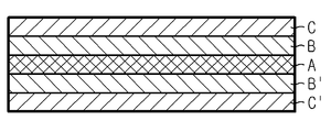
도 3은 본원 발명의 구체적인 일 실시양태에 따른 다층 분리막을 개략적으로 도시한 것이다. 도 3의 분리막은 제1 표면층부(C)/제1 내층부(B)/중심층부(A)/ 제2 내층부(B’)/제2 표면층부(C’)를 포함한다. 각 C/B/A/B’/C’는 각각 1개 또는 종류가 같거나 다른 2개 이상의 필름층을 포함할 수 있다. 3 schematically shows a multilayer separator according to one specific embodiment of the present invention. The separation membrane of FIG. 3 includes a first surface layer portion C / a first inner layer portion B / a center layer portion A / a second inner layer portion B '/ a second surface layer portion C'. Each C / B / A / B '/ C' may include one or more than two film layers of the same or different types.
본 발명의 구체적인 일 실시양태에 있어서, 상기 중심층부(A)에 포함되는 필름층들 중 최저 연신비를 갖는 필름층의 연신비는 내층부(B, B')에 포함되는 필름층들 중 최고 연신비를 갖는 필름층의 연신비 보다 높으며, 상기 내층부(B, B')에 포함되는 필름층들 중 가장 최저 연신비를 갖는 필름층의 연신비는 표면층부(C, C')에 포함되는 필름층들 중 최고 연신비를 갖는 필름층의 연신비 보다 높다. 동일 층부에 포함되는 필름층들은 서로 연신비가 서로 같거나 다를 수 있다. In one embodiment of the present invention, the stretching ratio of the film layer having the lowest stretch ratio among the film layers included in the center stratum part (A) is the stretch ratio of the film layers included in the inner layer parts (B, B ' And the stretching ratio of the film layer having the lowest stretching ratio among the film layers included in the inner layer portions B and B 'is higher than that of the film layers included in the surface layer portions C and C' Is higher than the stretching ratio of the film layer having the stretching ratio. The film layers included in the same layer portion may have the same or different stretching ratios.
본 발명의 다른 실시양태에 있어서, 상기 중심층부(A)에 포함되는 필름층들 중 어느 하나의 연신비는 내층부(B, B')에 포함되는 필름층들 중 최고 연신비를 갖는 필름층의 연신비 보다 높으며, 상기 내층부(B, B')에 포함되는 필름층들 어느 하나의 연신비는 표면층부(C, C')에 포함되는 필름층들 중 최고 연신비를 갖는 필름층의 연신비 보다 높다. 또한, 동일 층부에 포함되는 필름층들은 서로 연신비가 서로 같거나 다를 수 있다.
In another embodiment of the present invention, the stretching ratio of any one of the film layers included in the center stratum part A is set such that the stretching ratio of the film layer having the highest stretching ratio among the film layers included in the inner layer parts B and B ' And the stretching ratio of any of the film layers included in the inner layer portions B and B 'is higher than the stretching ratio of the film layer having the highest stretching ratio among the film layers included in the surface layer portions C and C'. Further, the film layers included in the same layer portion may have the same or different stretching ratios.
상기 중심층부(A)에 포함되는 필름층들은 연신비가 4 내지 8배 또는 5배 내지 7배인 것이다. 중심층부는 분리막의 내부에 포함되는 것으로서 다른 층에 비해 연신 비율이 높으며 이에 따라 강도가 기공도가 높아 분리막 전체의 강도 및 기공도 향상에 기여한다. 상기 중심층부(A)의 두께는 분리막 전체 두께 100% 대비 5% 내지 50%인 것이다. 상기 중심층부의 두께가 5% 미만인 경우에는 분리막의 강도가 저하될 수 있으며, 50%을 초과하는 경우에는 분리막에서 수축율이 높은 부분의 비율이 높아지므로 내열성이 저하될 수 있다. The film layers included in the center layer portion (A) have a stretching ratio of 4 to 8 times or 5 to 7 times. The center layer portion is contained in the separator and has a higher elongation ratio than the other layers. Accordingly, the strength and porosity of the core layer contribute to the improvement of the strength and porosity of the entire separator. The thickness of the center stratum part A is 5% to 50% of the entire thickness of the separator. If the thickness of the center layer portion is less than 5%, the strength of the separator may be decreased. If the thickness of the core layer portion is more than 50%, the proportion of the portion having a high shrinkage percentage may be increased.
상기 표면층부(C, C’)에 포함되는 필름층들은 연신비가 1배 내지 4배 또는 1배 내지 3배인 것이다. 표면층부는 분리막의 표층부를 형성하는 것으로서, 다른 층들에 비해 연신 비율이 낮아 잔존응력이 적으며 이에 따라 고온 완경에 노출되는 경우에도 분리막의 수축이 크지 않아 분리막의 내열성 및/또는 사용상 안전성 향상에 기여한다. The film layers included in the surface layer portions C and C 'have a stretching ratio of 1 to 4 times or 1 to 3 times. The surface layer portion forms a surface layer portion of the separation membrane and has a lower elongation ratio than other layers and thus has a small residual stress and thus does not shrink the separation membrane even when exposed to a high temperature temperature so that it contributes to improvement in heat resistance and / .
상기 표면층부(C, C’)의 두께는 분리막 전체 두께 100% 대비 5% 내지 50%인 것이다. 상기 중심층부의 두께가 5%미만인 경우에는 분리막의 내열성이 저하될 수 있으며, 중심층부가 수축됨에 따라 표면층부가 함께 수축되어 전극의 단락을 유발할 수 있어 바람직하지 않다. 반면에 50%을 초과하는 경우에는 분리막의 기공도가 저하되어 리튬 이온의 이동을 저해하여 저항이 증가될 수 있고 분리막의 젖음성이 저하될 수 있다.
The thickness of the surface layer portion (C, C ') is 5% to 50% of the entire thickness of the separation membrane. If the thickness of the center layer portion is less than 5%, the heat resistance of the separator may be deteriorated and the surface layer portion may shrink as the central layer portion shrinks, which may cause shorting of the electrode. On the other hand, if it exceeds 50%, the porosity of the separation membrane is lowered and the movement of the lithium ion is inhibited, so that the resistance can be increased and the wettability of the separation membrane can be lowered.
상기 내층부(B, B’)에 포함되는 필름층들은 연신비가 2배 내지 6배, 또는 3배 내지 5배인 것이다. 상기 내층부는 상기 중심층부 및 표층부 사이에 위치하며 중심층부가 수축되는 경우 수축에 의해 표면부층에 전달되는 응력을 차단하거나 감소하는 역할을 한다. 연신비의 차이가 큰 중심층부와 표면층부가 직접 맞닿아 라미네이트 되어 있는 경우 고온 환경에서 중심층부가 큰 수축율로 수축하여 변형되는 경우 변형에 의해 발생되는 응력이 표면층부로 전달되고 이로 인해 표면층부가 함께 수축될 수 있다. 이러한 문제 발생을 방지하기 위해 상기 표면층부와 중심층부 사이에 내층부를 더 구비하고 중심층부의 변형 응력을 내층부가 흡수 차단함으로써 표면층부의 손상을 방지할 수 있다. 상기 내층부(B, B’)의 두께는 분리막 전체 두께 100% 대비 5% 내지 50%인 것이다. 상기 내층부의 두께가 5%미만인 경우에는 기계적 강도가 저하되어 중심층부의 형태 변형 응력을 억제하지 못하여 내층부의 필름층이 변형 및/또는 손상될 수 있고 이는 분리막 전체의 형태 변형으로 이어질 수 있다. 예를 들어, 다층 분리막의 내열성이 저하될 수 있으며, 중심층부가 수축됨에 따라 표면층부가 함께 수축되어 전극의 단락을 유발할 수 있어 바람직하지 않다. 반면에 상기 내층부의 필름층이 50%을 초과하는 경우에는 분리막의 기공도가 저하되어 리튬 이온의 이동을 저해하여 저항이 증가될 수 있고 분리막의 젖음성이 저하될 수 있다.
The film layers included in the inner layer portions (B, B ') have stretching ratios of 2 to 6 times, or 3 to 5 times. The inner layer portion is located between the center layer portion and the surface layer portion and functions to block or reduce stress transmitted to the surface layer by shrinkage when the center layer portion is shrunk. In the case where the center layer portion having a large difference in stretching ratio is laminated by direct contact with the surface layer portion, when the center layer portion is shrunk and deformed at a high shrinkage ratio under a high temperature environment, the stress generated by the deformation is transmitted to the surface layer portion, have. In order to prevent such a problem from occurring, the inner layer portion is further provided between the surface layer portion and the center layer portion, and the deformation stress of the center layer portion is absorbed and blocked by the inner layer portion, thereby preventing damage to the surface layer portion. The thickness of the inner layer portion (B, B ') is 5% to 50% of the entire thickness of the separator. If the thickness of the inner layer portion is less than 5%, the mechanical strength of the inner layer portion may be lowered, so that the deformation stress of the center layer portion can not be suppressed and the film layer of the inner layer portion may be deformed and / or damaged. For example, the heat resistance of the multilayered separator may be deteriorated, and the surface layer may shrink together as the center layer shrinks, causing short-circuiting of the electrodes. On the other hand, when the film layer of the inner layer portion exceeds 50%, the porosity of the separation membrane is lowered and the movement of the lithium ion is inhibited, so that the resistance can be increased and the wettability of the separation membrane can be lowered.
다음으로 상기 다층 분리막의 제조 방법에 대해 설명한다. 그러나 하기 기술되는 제조 방법은 본원 발명의 다층 분리막을 제조하는 여러 방법 중 하나의 예시인 것으로서 본 발명의 상기 다층 분리막의 제조는 하기 방법으로 한정되는 것은 아니다. Next, a method of manufacturing the multilayered separator will be described. However, the manufacturing method described below is an example of one of various methods of manufacturing the multilayer separator of the present invention, and the production of the multilayer separator of the present invention is not limited to the following method.
상기 다층 분리막은 각 필름층들을 습식법 및/또는 건식법에 의해 준비하고 이들을 적층하여 제조될 수 있다. 본원 발명의 구체적인 일 실시양태에 따르면 상기 필름층은 건식 제조 방법에 따라 제조될 수 있다. 상기 건식 제조 방법은 본 발명이 속하는 기술분야에서 통상적으로 수행되는 방법이 사용될 수 있다. 건식 제조 방법은 연신으로 폴리머 박막에 미세 크랙을 발생시켜 다공화하는 방법이다. 또한, 상기 필름층은 습식법에 의해 제조될 수 있다. 상기 습식 제조 방법은 폴리에틸렌 수지를 고온에서 기공형성제와 혼련하여 단일상을 만들고, 냉각 과정에서 폴리올레핀과 기공형성제를 상분리시킨 후, 기공형성제 부분을 추출시켜 폴리올레핀에 기공을 형성시키는 방법이다. The multilayer separation membrane may be prepared by preparing each film layer by a wet method and / or a dry method and laminating them. According to a specific embodiment of the present invention, the film layer can be produced according to a dry manufacturing method. As the dry manufacturing method, a method which is generally performed in the technical field of the present invention can be used. The dry-type method is a method in which micro-cracks are generated in the polymer thin film by stretching. Further, the film layer can be produced by a wet process. The wet process is a method of kneading a polyethylene resin with a pore-forming agent at a high temperature to form a single phase, separating the polyolefin and the pore-forming agent during the cooling process, and then extracting the pore-forming agent portion to form pores in the polyolefin.
건식 또는 습식 방법에 의해 미연신 필름을 얻은 후 이러한 미배향 상태의 고분자를 융점 이하, 일반적으로 2차 전이점 이상의 온도에서 1축 또는 2축 방향으로 연신하여 늘려 분자를 그 방향으로 배향시킨다. 이에 의해 필름의 충격강도와 투명성이 증가하고 차단성이 증가되며, 필름의 결정화도가 높아진다. 또한, 연신에 의해 필름 중 미세 기공이 형성되어 기공도가 높아진다.After the unstretched film is obtained by a dry or wet method, the unmodified polymer is stretched in the uniaxial or biaxial direction at a temperature not lower than the melting point, generally at the second transition point or higher, and the molecules are oriented in that direction. This increases the impact strength and transparency of the film, increases the barrier property, and increases the crystallinity of the film. In addition, micropores are formed in the film by stretching to increase the porosity.
다음으로 상기 연신 처리를 거친 필름들은 잔류응력을 제거하여 최종 필름의 수축률을 감소시키기 위해 열고정 단계를 거친다. 열고정 공정은 열을 가한 상태에서 수축하려는 필름을 강제로 잡아주어 잔류응력을 제거하는 것으로 열고정 온도와 고정 비율에 따라 수축률과 고온 천공강도는 영향을 받는다. 열고정 온도가 높으면 수지의 응력이 낮아져 수축률이 작아지고 고온 천공강도도 높아지게 된다. 천공강도는 측정 온도가 상승할수록 수지의 응력완화가 발생하면서 낮아지는 현상이 나타나지만 열고정 온도가 높은 경우에는 열고정 과정에서 충분한 응력완화가 이루어져 온도 상승에 따른 천공강도 감소폭이 크지 않아 고온 천공강도가 높게 되는 것이다. 그러나, 열고정 온도가 너무 높을 경우 필름이 부분적으로 녹아 형성된 미세다공이 막혀 투과도가 저하된다. 바람직한 열고정 온도는 폴리에틸렌층의 결정부분의 10~40중량%가 녹는 온도범위에서 선택되는 것이 좋다. 상기 열고정 온도가 상기 폴리에틸렌층의 결정부분의 10중량%가 녹는 온도보다 낮은 온도범위에서 선택되면 필름 내 폴리에틸렌 분자의 재배열(reorientation)이 미비하여 필름의 잔류 응력 제거효과가 없으며, 폴리에틸렌층의 결정부분의 40중량%가 녹는 온도보다 높은 온도범위에서 선택되면 부분적 용융에 의하여 미세다공이 막혀 투과도가 저하된다. 또한 열고정시 텐터 형식의 기계를 이용해 단계별 열고정을 하여 인장강도와 천공강도 등의 기계적 물성을 향상시키고 수축률을 감소시킬 수 있다. 열고정 과정에서 첫번째 단계에서 20~50%만큼 횡방향으로 연신하여 투과도를 증가시키고 인장강도와 천공강도를 향상시킨다. 50%를 초과하여 연신하면 투과도 및 인장강도가 향상되는 장점이 있는 반면에 수축률이 커지고 횡방향의 배향성이 증가하여 횡방향 TMA 수축률도 증가하고 기공의 크기가 과도하게 증가하는 단점이 있다. 두번째 단계에서는 첫번째 연신된 필름의 폭을 15 ~ 40% 가량 수축시킨다. 열을 가한 상태에서 횡방향 수축을 통해 응력을 완화시키고 수지의 배향성을 완화하여 수축률과 횡방향 TMA 수축률을 감소시킨다. 이때 40%이상으로 필름의 폭을 수축시키면 투과도와 천공강도가 과도하게 낮아지는 문제가 있고 15%이하로 수축을 시키면 응력 및 수지 배향성이 완화가 되지 않아 수축률과 횡방향 TMA 수축률이 커지고 기공의 크기가 크게 유지되어 전지의 안정성을 확보할 수 없다. 그리고, 열고정 시간은 열고정 온도가 높을 경우는 상대적으로 짧게, 열고정 온도가 낮을 경우는 상대적으로 길게 할 수 있다. 바람직하게는 15초~1분 정도가 적당하다.
Next, the films subjected to the stretching treatment are subjected to a heat fixing step to remove residual stress and reduce the shrinkage ratio of the final film. In the heat-setting process, the film to be shrunk is forced by holding the heat to remove the residual stress, and the shrinkage rate and the high-temperature puncture strength are affected by the fixing temperature and the fixing ratio. If the heat fixing temperature is high, the stress of the resin lowers, the shrinkage rate becomes small, and the high temperature puncture strength becomes high. The puncture strength decreases as the measured temperature rises as the stress relaxation of the resin occurs. However, when the heat fixation temperature is high, sufficient stress relaxation is performed in the heat fixation process, It will be higher. However, when the heat fixing temperature is too high, the film is partially melted and the formed micropores are clogged to degrade the permeability. The preferred heat-setting temperature is selected within a temperature range where 10 to 40% by weight of the crystalline portion of the polyethylene layer is melted. If the heat fixing temperature is selected in a temperature range lower than the melting point of 10 wt% of the crystalline portion of the polyethylene layer, reorientation of the polyethylene molecules in the film is insufficient and there is no effect of removing the residual stress of the film. If the temperature is higher than the melting temperature of 40 wt% of the crystalline portion, the micropores are blocked by partial melting and the permeability is lowered. In addition, it is possible to improve the mechanical properties such as tensile strength and piercing strength and to reduce the shrinkage rate by performing heat fixing stepwise by using an open and regular tenter type machine. In the first step in the heat setting process, the transverse direction is elongated by 20 to 50% to increase the transmittance and improve the tensile strength and the puncture strength. The stretching of more than 50% has the advantage of improving the transmittance and tensile strength, but it has a disadvantage in that the shrinkage ratio increases and the transverse directional orientation increases, so that the transverse TMA shrinkage increases and the pore size excessively increases. In the second step, the width of the first stretched film is reduced by 15 to 40%. In the state of applying heat, it relaxes the stress through transverse shrinkage and alleviates the orientation of the resin, thereby reducing the shrinkage ratio and the transverse TMA shrinkage. At this time, when the width of the film is shrunk to 40% or more, the transparency and the puncture strength are excessively lowered. When the shrinkage is less than 15%, the stress and the resin orientation are not alleviated and the shrinkage ratio and the transverse TMA shrinkage ratio are increased. The stability of the battery can not be ensured. The heat setting time can be relatively short when the heat setting temperature is high, and relatively long when the heat setting temperature is low. Preferably 15 seconds to 1 minute.
다음으로, 전술한 방법으로 연신비가 서로 다른 각각의 필름층을 제조한 후 이를 적층하여 다층 분리막을 제조한다. 적층된 각 필름층 사이에는 층간 접착을 위해 접착층(미도시)이 개재될 수 있다. 또는 각각의 필름을 순차적으로 적층하여 적층 구조체를 형성하고 상기 적층 구조체를 압착하여 층간 접착을 달성할 수 있다. 상기 필름층을 적층하는 방법은 예를 들어 가열 및 가압 조건에서 각 필름층을 접합할 수 있다. 그러나 상기 방법에 한정되는 것은 아니며, 본원 발명의 범위 내에서 다양한 방법이 적용될 수 있다.
Next, each of the film layers having different stretching ratios is produced by the above-mentioned method, and then laminated to produce a multilayered separator. An adhesive layer (not shown) may be interposed between the laminated film layers for interlayer adhesion. Or each film may be sequentially laminated to form a laminated structure, and the laminated structure may be pressed to achieve interlayer adhesion. As a method of laminating the film layers, for example, each film layer can be bonded under heating and pressurizing conditions. However, the present invention is not limited to the above method, and various methods can be applied within the scope of the present invention.
전술한 바와 같이 본원 발명의 다층 분리막은 분리막 중심부에서 표면부까지 순차적으로 및/또는 단계적으로 연신비가 감소하고, 강도가 높은 고연신 필름층이 중심부에 위치하고 통기도가 우수한 저연신 필름층이 표면부에 위치하게 되므로 통기도가 우수하면서도 기계적 강도가 향상된다. 본원 발명에 따른 분리막은 100gf 내지 1,000gf의 관통강도를 가지며, 50sec/100cc 내지 800sec/100cc의 통기도를 갖는다. 상기 관통강도와 통기도는 본 발명의 범위 내에서 각 필름층의 두께 등 물성을 조절하여 최종 제품의 사용 목적에 따라 적절한 범위를 선택할 수 있다.
As described above, the multilayer separation membrane of the present invention is characterized in that the stretching ratio is gradually decreased and / or stepwise from the center portion of the separation membrane to the surface portion, and the low stretched film layer having the high- The mechanical strength is improved while the air permeability is excellent. The separation membrane according to the present invention has a penetration strength of 100 gf to 1,000 gf and an air permeability of 50 sec / 100cc to 800sec / 100cc. The penetration strength and air permeability may be appropriately selected depending on the intended use of the final product by controlling physical properties such as the thickness of each film layer within the scope of the present invention.
본원 발명의 구체적인 일 실시양태에 따르면 상기 다층 분리막은 일측 또는 양측 표면에 무기물 입자를 포함하는 세라믹 다공성 코팅층이 더 형성될 수 있다. According to a specific embodiment of the present invention, the multilayer separation membrane may further include a ceramic porous coating layer including inorganic particles on one or both surfaces thereof.
상기 무기물 입자는 무기물 입자들간의 빈 공간(interstitial volume)을 형성하여 미세 기공을 제공하는 역할을 한다. 또한 물리적 형태를 유지할 수 있는 일종의 스페이서(spacer) 역할을 겸하게 된다. 추가적으로 상기 무기물 입자는 일반적으로 200℃ 이상의 고온이 되어도 물리적 특성이 변하지 않는 특성을 갖기 때문에, 형성된 세라믹 다공성 코팅층에 의해 세퍼레이터는 우수한 내열성을 갖게 된다. 상기 다공성 코팅층은 두께가 1㎛ 내지 30㎛, 또는 2㎛ 내지 20㎛인 또는 2㎛ 내지 14㎛인 것이다.
The inorganic particles form an interstitial volume between inorganic particles to provide micropores. It also serves as a kind of spacer capable of maintaining the physical form. In addition, since the inorganic particles generally have a characteristic that their physical properties do not change even at a high temperature of 200 DEG C or more, the formed ceramic porous coating layer has excellent heat resistance. The porous coating layer has a thickness of 1 탆 to 30 탆, or 2 탆 to 20 탆, or 2 탆 to 14 탆.
상기 무기물 입자의 크기는 제한이 없으나, 균일한 두께의 필름 형성 및 적절한 공극률을 위하여 0.001 내지 10㎛ 범위인 것이 바람직하며, 세라믹 다공성 코팅층이 형성되는 기재(다공성 막 또는 부직포 웹)의 기공도를 참조하여 적절하게 조절할 수 있다. 입자의 크기가 0.001㎛ 미만인 경우 분산성이 저하되어 세라믹 다공성 코팅층의 물성을 조절하기가 어려우며, 10㎛를 초과하는 경우 세라믹 다공성 코팅층의 두께가 증가하여 기계적 물성이 저하되며, 또한 지나치게 큰 기공 크기로 인해 전지 충방전시 내부 단락이 일어날 확률이 높아진다.
Although the size of the inorganic particles is not limited, it is preferably in the range of 0.001 to 10 μm for the formation of a film having a uniform thickness and an appropriate porosity, and the porosity of the substrate (porous film or nonwoven web) on which the ceramic porous coating layer is formed And can be appropriately adjusted. When the particle size is less than 0.001 탆, the dispersibility is lowered and it is difficult to control the physical properties of the ceramic porous coating layer. When the particle size exceeds 10 탆, the thickness of the ceramic porous coating layer is increased to decrease the mechanical properties, The probability of an internal short circuit occurring during charging and discharging of the battery increases.
상기 무기물 입자의 함량은 세라믹 다공성 코팅층을 구성하는 무기물 입자와 바인더 고분자 수지의 혼합물 100중량% 당 50 중량% 내지 99 중량% 범위가 바람직하며, 특히 60 증량% 내지 95 중량%가 더욱 바람직하다.
The content of the inorganic particles is preferably in the range of 50% by weight to 99% by weight, more preferably 60% by weight to 95% by weight, based on 100% by weight of the mixture of the inorganic particles constituting the ceramic porous coating layer and the binder polymer resin.
상기 바인더 고분자 수지는 당 업계에서 통상적으로 사용되는 고분자 수지를 사용할 수 있다. 특히, 유리 전이 온도(glass transition temperature, Tg)가 가능한 낮은 것을 사용할 수 있으며, 바람직하게는 -200 내지 200℃ 범위이다. 이는 최종 필름의 유연성 및 탄성 등과 같은 기계적 물성을 향상시킬 수 있기 때문이다. 상기 고분자 수지는 무기물 입자들과 입자 사이를 연결 및 안정하게 고정시켜주는 바인더 역할을 충실히 수행함으로써, 최종 제조되는 세라믹 다공성 코팅층의 기계적 물성 저하 방지에 기여한다.
The binder polymer resin may be a polymer resin conventionally used in the art. Particularly, it is possible to use a glass transition temperature (Tg) as low as possible, preferably in the range of -200 to 200 ° C. This is because the mechanical properties such as flexibility and elasticity of the final film can be improved. The polymer resin faithfully performs a binder function to connect and stably fix inorganic particles and particles, thereby contributing to prevention of deterioration of mechanical properties of the finally formed ceramic porous coating layer.
본원 발명의 일 실시양태에 따르면 상기 세라믹 다공성 코팅층은 무기물 입자, 바인더 고분자 수지를 적절한 용매와 혼합하여 세라믹 다공성 코팅층용 슬러리를 제조한 후 이를 적용 대상인 기재 표면에 딥 코팅법이나 닥터블레이드 코팅법과 같은 공지의 방법으로 상기 슬러리를 도포하고 이를 건조하여 형성할 수 있다.
According to one embodiment of the present invention, the ceramic porous coating layer is prepared by mixing an inorganic particle and a binder polymer resin with an appropriate solvent to prepare a slurry for a ceramic porous coating layer, The slurry may be applied and dried to form the slurry.
본원 발명에 있어서, 상기 슬러리에 포함되는 무기 입자는 전기화학적으로 안정하기만 하면 특별히 제한되지 않는다. 즉, 상기 무기 입자는 적용되는 전기화학소자의 작동 전압 범위(예컨대, Li/Li+ 기준으로 0~5V)에서 산화 및/또는 환원 반응이 일어나지 않는 것이면 특별히 제한되지 않는다. 특히, 이온 전달 능력이 있는 무기 입자를 사용하는 경우 전기화학소자 내의 이온 전도도를 높여 성능 향상을 도모할 수 있다. 또한, 무기 입자로서 유전율이 높은 무기 입자를 사용하는 경우, 액체 전해질 내 전해질 염, 예컨대 리튬염의 해리도 증가에 기여하여 전해액의 이온 전도도를 향상시킬 수 있다.
In the present invention, the inorganic particles contained in the slurry are not particularly limited as long as they are electrochemically stable. That is, the inorganic particles are not particularly limited as long as the oxidation and / or reduction reaction does not occur in the operating voltage range of the applied electrochemical device (for example, 0 to 5 V based on Li / Li +). Particularly, when inorganic particles having ion transfer ability are used, the ion conductivity in the electrochemical device can be increased to improve the performance. When inorganic particles having a high dielectric constant are used as the inorganic particles, dissociation of an electrolyte salt, for example, a lithium salt, in the liquid electrolyte is also increased, so that the ion conductivity of the electrolyte can be improved.
전술한 이유들로 인해, 상기 무기 입자는 유전율 상수가 5 이상, 또는 10 이상인 고유전율 무기 입자, 리튬 이온 전달 능력을 갖는 무기 입자 또는 이들의 혼합체를 포함할 수 있다. 유전율 상수가 5 이상인 무기 입자의 비제한적인 예로는 BaTiO3, Pb(Zr,Ti)O3 (PZT), Pb1-xLaxZr1-yTiyO3 (PLZT, 여기서, 0 < x < 1, 0 < y < 1임), Pb(Mg1/3Nb2/3)O3-PbTiO3 (PMN-PT), 하프니아(HfO2), SrTiO3, SnO2, CeO2, MgO, NiO, CaO, ZnO, ZrO2, Y2O3, Al2O3, SiC, TiO2등을 각각 단독으로 또는 2종 이상을 혼합하여 사용할 수 있다. 특히, 전술한 BaTiO3, Pb(Zr,Ti)O3 (PZT), Pb1-xLaxZr1-yTiyO3 (PLZT, 여기서, 0 < x < 1, 0 < y < 1임), Pb(Mg1/3Nb2/3)O3-PbTiO3 (PMN-PT), 하프니아(HfO2)와 같은 무기 입자들은 유전율 상수 100 이상인 고유전율 특성을 나타낼 뿐만 아니라, 일정 압력을 인가하여 인장 또는 압축되는 경우 전하가 발생하여 양쪽 면 간에 전위차가 발생하는 압전성(piezoelectricity)을 가짐으로써, 외부 충격에 의한 양(兩) 전극의 내부 단락 발생을 방지하여 전기화학소자의 안전성 향상을 도모할 수 있다. 또한, 전술한 고유전율 무기 입자와 리튬 이온 전달 능력을 갖는 무기 입자들을 혼용할 경우 이들의 상승 효과는 배가될 수 있다.
For the reasons stated above, the inorganic particles may include high-permittivity inorganic particles having a dielectric constant of 5 or more, or 10 or more, inorganic particles having lithium ion transferring ability, or a mixture thereof. Non-limiting examples of the inorganic particles having a dielectric constant of 5 or more include BaTiO 3 , Pb (Zr, Ti) O 3 (PZT), Pb 1 -x La x Zr 1 -y Ti y O 3 (PLZT, Pb (Mg 1/3 Nb 2/3 ) O 3 -PbTiO 3 (PMN-PT), hafnia (HfO 2 ), SrTiO 3 , SnO 2 , CeO 2 , MgO , NiO, CaO, ZnO, ZrO 2 , Y 2 O 3 , Al 2 O 3 , SiC, and TiO 2 may be used alone or in combination of two or more. Particularly, the above-mentioned BaTiO 3 , Pb (Zr, Ti) O 3 (PZT), Pb 1 -x La x Zr 1 -y Ti y O 3 (PLZT, where 0 <x <1, 0 < Inorganic particles such as Pb (Mg 1/3 Nb 2/3 ) O 3 -PbTiO 3 (PMN-PT) and hafnia (HfO 2 ) exhibit a high dielectric constant of 100 or more, And a piezoelectricity is generated so that a potential difference is generated between both sides by generating a charge when being stretched or compressed so as to prevent the occurrence of an internal short circuit between the two electrodes due to an external impact so as to improve the safety of the electrochemical device can do. Further, when the above-mentioned high-permittivity inorganic particles and inorganic particles having lithium ion-transferring ability are mixed, their synergistic effect can be doubled.
본 발명에서 리튬 이온 전달 능력을 갖는 무기 입자는 리튬 원소를 함유하되 리튬을 저장하지 아니하고 리튬 이온을 이동시키는 기능을 갖는 무기 입자를 지칭하는 것으로서, 리튬 이온 전달 능력을 갖는 무기 입자는 입자 구조 내부에 존재하는 일종의 결함(defect)으로 인해 리튬 이온을 전달 및 이동시킬 수 있기 때문에, 전지 내 리튬 이온 전도도가 향상되고, 이로 인해 전지 성능 향상을 도모할 수 있다. 상기 리튬 이온 전달 능력을 갖는 무기 입자의 비제한적인 예로는 리튬포스페이트(Li3PO4), 리튬티타늄포스페이트(LixTiy(PO4)3, 0 < x < 2, 0 < y < 3), 리튬알루미늄티타늄포스페이트(LixAlyTiz(PO4)3, 0 < x < 2, 0 < y < 1, 0 < z < 3), 14Li2O-9Al2O3-38TiO2-39P2O5 등과 같은 (LiAlTiP)xOy 계열 glass (0 < x < 4, 0 < y < 13), 리튬란탄티타네이트(LixLayTiO3, 0 < x < 2, 0 < y < 3), Li3.25Ge0.25P0.75S4등과 같은 리튬게르마니움티오포스페이트(LixGeyPzSw, 0 < x < 4, 0 < y < 1, 0 < z < 1, 0 < w < 5), Li3N 등과 같은 리튬나이트라이드(LixNy, 0 < x < 4, 0 < y < 2), Li3PO4-Li2S-SiS2 등과 같은 SiS2 계열 glass(LixSiySz, 0 < x < 3, 0 < y < 2, 0 < z < 4), LiI-Li2S-P2S5등과 같은 P2S5 계열 glass(LixPySz, 0 < x < 3, 0 < y < 3, 0 < z < 7) 또는 이들의 혼합물 등이 있다.
In the present invention, the inorganic particles having a lithium ion-transferring ability refer to inorganic particles containing a lithium element but not lithium and having a function of moving lithium ions. The inorganic particles having a lithium ion- Since lithium ions can be transferred and transferred due to a kind of defect present, the lithium ion conductivity in the battery is improved, thereby improving battery performance. Examples of the inorganic particles having lithium ion transferring ability include lithium phosphate (Li 3 PO 4 ), lithium titanium phosphate (Li x Ti y (PO 4 ) 3 , 0 <x <2, 0 <y < (Li x Al y Ti z (PO 4 ) 3 , 0 <x <2, 0 <y <1, 0 <z <3), 14Li 2 O-9Al 2 O 3 -38TiO 2 -39P 2 O 5 as such (LiAlTiP) x O y series glass (0 <x <4, 0 <y <13), lithium lanthanum titanate (Li x La y TiO 3, 0 <x <2, 0 <y <3 ), Li 3.25 Ge 0.25 P 0.75 S 4 lithium germanate Mani help thiophosphate (Li x Ge y P z S w, 0 <x <4, 0 <y <1, 0 <z <1, 0 <w , such as < 5), Li 3 N lithium nitride (Li x N y, 0 < x <4, 0 <y <2), Li 3 PO 4 SiS 2 family, such as -Li 2 S-SiS 2 glass ( Li x such as Si y S z, 0 <x <3, 0 <y <2, 0 <z <4), LiI-Li 2 SP 2 S 5 P 2 S 5 based glass (Li x P y S z, such as 0 < x <3, 0 <y <3, 0 <z <7), or mixtures thereof.
한편, 유/무기 복합 다공층의 기공 크기 및 기공도는 주로 무기 입자의 크기에 의존하는데, 예컨대 입경이 1㎛ 이하인 무기 입자를 사용하는 경우, 형성되는 기공 역시 1㎛ 이하가 된다. 이와 같은 기공 구조는 추후 주액되는 전해액으로 채워지게 되고, 이와 같이 채워진 전해액은 이온 전달 역할을 하게 된다. 따라서 상기 기공의 크기 및 기공도는 유/무기 복합 다공성 필름의 이온 전도도 조절에 중요한 영향 인자이다. 본원 발명의 유/무기 복합 다공층의 기공 크기 및 기공도(porosity)는 각각 0.001 내지 10㎛이고, 5 내지 95% 범위인 것이 바람직하다.
On the other hand, the pore size and porosity of the organic / inorganic composite porous layer depends mainly on the size of the inorganic particles. For example, when inorganic particles having a particle size of 1 탆 or less are used, pores to be formed also become 1 탆 or less. Such a pore structure is filled with an electrolyte solution to be injected at a later stage, and the filled electrolyte serves as an ion transfer function. Therefore, the pore size and porosity are important factors for controlling the ionic conductivity of the organic / inorganic composite porous film. The pore size and the porosity of the organic / inorganic composite porous layer of the present invention are preferably 0.001 to 10 μm, and preferably 5 to 95%.
또한, 본 발명의 유/무기 복합 다공층의 두께는 특별한 제한은 없으나 전지 성능을 고려하여 조절될 수 있다. 1 내지 100㎛ 범위인 것이 바람직하며, 특히 2 내지 30㎛ 범위인 것이 더욱 바람직하다. 상기 두께 범위를 조절함으로써 전지 성능 향상을 도모할 수 있다.In addition, the thickness of the organic / inorganic composite porous layer of the present invention is not particularly limited, but may be adjusted in consideration of cell performance. More preferably in the range of 1 to 100 mu m, and particularly preferably in the range of 2 to 30 mu m. By adjusting the thickness range, battery performance can be improved.
본원 발명에 따른 분리막은 에너지 저장장치와 같은 전기 화학 소자에 분리막으로 이용이 가능하다. 상기 전기 화학 소자는 전기 화학 반응을 하는 모든 소자를 포함하며, 구체적인 예를 들면, 모든 종류의 일차 전지, 이차 전지, 연료 전지, 태양 전지 또는 슈퍼 커패시터 소자와 같은 커패시터(capacitor) 등이 있다. 특히, 상기 이차 전지 중 리튬 금속 이차 전지, 리튬 이온 이차 전지, 리튬 폴리머 이차 전지 또는 리튬 이온 폴리머 이차 전지 등을 포함하는 리튬 이차전지가 바람직하다.
The separation membrane according to the present invention can be used as a separation membrane in an electrochemical device such as an energy storage device. The electrochemical device includes all devices that perform an electrochemical reaction. Specific examples of the electrochemical device include a capacitor such as a primary cell, a secondary cell, a fuel cell, a solar cell, or a supercapacitor. Particularly, a lithium secondary battery including a lithium metal secondary battery, a lithium ion secondary battery, a lithium polymer secondary battery, or a lithium ion polymer secondary battery among the above secondary batteries is preferable.
Claims (15)
Wherein the stretching ratio of each of the film layers is gradually or sequentially decreased from the center to the surface along a direction perpendicular to the lamination interface of the film layers, Battery separator.
상기 다공성 필름층은 폴리올레핀계 고분자 수지를 포함하는 것인, 이차 전지용 분리막.
The method according to claim 1,
Wherein the porous film layer comprises a polyolefin-based polymer resin.
상기 분리막은 중심층부, 상기 중심층부의 양측면상에 위치하는 제1 및 제2 내층부, 상기 제1 내층부상에 위치하는 제1 표면층부 및 상기 제2 내층부상에 위치하는 제2 표면층부를 포함하며, 상기 중심층부에 포함되는 필름층들의 연신비는 4배 내지 8배이고, 상기 제1 및 제2 내층부에 포함되는 필름층들의 연신비는 2배 내지 5배이고, 상기 제1 및 제2 표면층부에 포함되는 필름층들의 연신비는 1배 내지 4배인, 이차 전지용 분리막.
The method according to claim 1,
The separation membrane includes a center layer portion, first and second inner layer portions located on both sides of the center layer portion, a first surface layer portion located on the first inner layer portion, and a second surface layer portion located on the second inner layer portion, , The stretching ratio of the film layers included in the center layer portion is 4 to 8 times, the stretching ratio of the film layers included in the first and second inner layer portions is 2 to 5 times, and the stretching ratio of the film layers included in the first and second surface layer portions Wherein the stretching ratio of the film layers is 1 to 4 times.
상기 중심층부는 분리막의 전체 두께 100% 대비 5 내지 50%에 해당하는 것인, 이차 전지용 분리막.
The method of claim 3,
Wherein the center layer portion corresponds to 5 to 50% of the total thickness of the separator.
상기 제1 및 제2 표면층부의 총 두께는 분리막의 전체 두께의 5% 내지 50%에 해당하는 것인, 이차 전지용 분리막.
The method of claim 3,
Wherein the total thickness of the first and second surface layer portions is 5% to 50% of the total thickness of the separator.
상기 제1 및 제2 내층부의 총 두께는 분리막 전체 두께 100% 내지 5% 내지 50%에 해당하는 것인, 이차 전지용 분리막.
The method of claim 3,
Wherein the total thickness of the first and second inner layers corresponds to 100% to 5% to 50% of the total thickness of the separator.
상기 중심층부에 포함되는 필름층들 중 최저 연신비를 갖는 필름층의 연신비는 상기 제1 및 제2 내층부에 포함되는 필름층들 중 최고 연신비를 갖는 필름층의 연신비 보다 높으며, 상기 제1 및 제2 내층부에 포함되는 필름층들 중 가장 최저 연신비를 갖는 필름층의 연신비는 상기 제1 및 제2 표면층부에 포함되는 필름층들 중 최고 연신비를 갖는 필름층의 연신비 보다 높은 것인, 이차 전지용 분리막.
The method of claim 3,
The stretching ratio of the film layer having the lowest stretching ratio among the film layers included in the center stratum is higher than the stretching ratio of the film stratum having the highest stretching ratio among the film layers included in the first and second inner layer portions, Wherein the stretching ratio of the film layer having the lowest stretching ratio among the film layers included in the inner layer portion is higher than the stretching ratio of the film layer having the highest stretching ratio among the film layers included in the first and second surface layer portions, Membrane.
상기 중심층부에 포함되는 필름층들 중 어느 하나의 연신비는 제1 및 제2 내층부에 포함되는 필름층들 중 최고 연신비를 갖는 필름층의 연신비 보다 높으며, 상기 제1 및 제2 내층부에 포함되는 필름층들 어느 하나의 연신비는 상기 제1 및 제2 표면층부에 포함되는 필름층들 중 최고 연신비를 갖는 필름층의 연신비 보다 높은 것인, 이차 전지용 분리막.
The method of claim 3,
The stretching ratio of any one of the film layers included in the center layer portion is higher than the stretching ratio of the film layer having the highest stretch ratio among the film layers included in the first and second inner layer portions and is included in the first and second inner layer portions Wherein the stretching ratio of one of the film layers is higher than the stretching ratio of the film layer having the highest stretching ratio among the film layers included in the first and second surface layer portions.
상기 분리막은 통기도가 50sec/100cc 내지 800sec/100cc인 것인, 이차 전지용 분리막.
The method according to claim 1,
Wherein the separation membrane has an air permeability of 50 sec / 100cc to 800sec / 100cc.
상기 분리막은 관통강도가 100gf 내지 1,000gf인 것인, 이차 전지용 분리막.
The method according to claim 1,
Wherein the separation membrane has a penetration strength of 100 gf to 1,000 gf.
상기 분리막은, 최외부면에 무기물 입자 및 바인더 고분자 수지를 포함하는 세라믹 다공성 코팅층을 더 포함하는 것인, 이차 전지용 분리막.
The method according to claim 1,
Wherein the separation membrane further comprises a ceramic porous coating layer including inorganic particles and a binder polymer resin on the outermost surface.
상기 세라믹 다공성 코팅층은 무기물 입자들이 바인더 고분자 수지를 매개로 하여 입자간 점결착 및/또는 면결착하여 서로 고정되어 있으며, 무기물 입자들의 인터스티셜 볼륨(interstitial volume)에 의해 형성된 복수의 미세 기공을 갖는 다공성 구조인 것인, 이차 전지용 분리막.
12. The method of claim 11,
The ceramic porous coating layer is formed of inorganic particles having a plurality of fine pores formed by the interstitial volume of inorganic particles, which are fixed to each other by point bonding and / or face binding between particles via a binder polymer resin Wherein the separator has a porous structure.
상기 다공성 코팅층의 두께는 1㎛ 내지 30㎛인, 이차 전지용 분리막.
10. The method of claim 9,
Wherein the thickness of the porous coating layer is 1 to 30 占 퐉.
A cathode, an anode, and a separator interposed between the cathode and the anode, wherein the separator is the separator according to any one of claims 1 to 13.
상기 전기화학소자는 이차 전지, 리튬 이온 이차 전지, 리튬 금속 이차 전지, 연료전지, 태양 전지 또는 슈퍼 커패시터인 것인, 전기화학소자. 15. The method of claim 14,
Wherein the electrochemical device is a secondary battery, a lithium ion secondary battery, a lithium metal secondary battery, a fuel cell, a solar cell, or a supercapacitor.
Priority Applications (1)
| Application Number | Priority Date | Filing Date | Title |
|---|---|---|---|
| KR1020140150463A KR101841808B1 (en) | 2014-10-31 | 2014-10-31 | A separator for a secondary battery |
Applications Claiming Priority (1)
| Application Number | Priority Date | Filing Date | Title |
|---|---|---|---|
| KR1020140150463A KR101841808B1 (en) | 2014-10-31 | 2014-10-31 | A separator for a secondary battery |
Publications (2)
| Publication Number | Publication Date |
|---|---|
| KR20160051069A true KR20160051069A (en) | 2016-05-11 |
| KR101841808B1 KR101841808B1 (en) | 2018-05-04 |
Family
ID=56025909
Family Applications (1)
| Application Number | Title | Priority Date | Filing Date |
|---|---|---|---|
| KR1020140150463A Active KR101841808B1 (en) | 2014-10-31 | 2014-10-31 | A separator for a secondary battery |
Country Status (1)
| Country | Link |
|---|---|
| KR (1) | KR101841808B1 (en) |
Families Citing this family (1)
| Publication number | Priority date | Publication date | Assignee | Title |
|---|---|---|---|---|
| KR102260464B1 (en) | 2020-12-02 | 2021-06-07 | 표준머신비전 주식회사 | Inspection apparatus and method for reel appearance of separation coating film |
-
2014
- 2014-10-31 KR KR1020140150463A patent/KR101841808B1/en active Active
Also Published As
| Publication number | Publication date |
|---|---|
| KR101841808B1 (en) | 2018-05-04 |
Similar Documents
| Publication | Publication Date | Title |
|---|---|---|
| US12134259B2 (en) | Laminated multilayer membranes, separators, batteries, and methods | |
| KR101504223B1 (en) | Improved stack-type cell and Bi-cell, electrode assembly for secondary battery utilizing the same and manufacturing method thereof | |
| KR102544195B1 (en) | Improved multilayer microporous separators for lithium ion secondary batteries and related methods | |
| EP3026733A1 (en) | Separator for electrochemical device | |
| KR101943502B1 (en) | A method for manufacturing a separator for a lithium secondary battery and the separator fabricated by the same | |
| KR20150128973A (en) | Multilayer hybrid battery separators for lithium ion secondary batteries and methods of making same | |
| KR20180005258A (en) | Improved low resistance microporous battery separators, separators, cells, batteries and related methods. | |
| KR101792749B1 (en) | Tri-layered separator for secondary battery, secondary battery comprising the same, and method of preparing the separator | |
| US12506224B2 (en) | Porous substrate for separator and separator for electrochemical device comprising same | |
| EP3787067B1 (en) | Separator for electrochemical device and electrochemical device including the same | |
| US20250260125A1 (en) | Substrate for separator of electrochemical device, separator including same, and method of forming battery cell separator | |
| KR102715588B1 (en) | Separator, electrochemical device comprising the same and manufacturing method for separator | |
| KR102477279B1 (en) | Separator and electrochemical device including the same | |
| KR101726382B1 (en) | A stack/folding type electrode assembly with safety improvement and a electrochemical cell comprising the same | |
| KR101780036B1 (en) | A stack/folding type electrode assembly with safety improvement and a electrochemical cell comprising the same | |
| KR101816764B1 (en) | A method of manufacturing separator for electrochemical device and separator for electrochemical device manufactured thereby | |
| JP7463638B2 (en) | Apparatus and method for manufacturing unit cells | |
| KR101841808B1 (en) | A separator for a secondary battery | |
| KR101910222B1 (en) | A multi-layered separator having high heat resistance property for a secondary battery | |
| KR102902565B1 (en) | The Apparatus And The Method For Manufacturing Unit Cell | |
| KR102137708B1 (en) | Separator with barrier, method of making the same and electrode assembly comprising the same | |
| KR101750237B1 (en) | Method for Preparing Unit Cell of Asymmetirc Structure and Unit Cell Prepared thereby |
Legal Events
| Date | Code | Title | Description |
|---|---|---|---|
| PA0109 | Patent application |
Patent event code: PA01091R01D Comment text: Patent Application Patent event date: 20141031 |
|
| N231 | Notification of change of applicant | ||
| PN2301 | Change of applicant |
Patent event date: 20151216 Comment text: Notification of Change of Applicant Patent event code: PN23011R01D |
|
| A201 | Request for examination | ||
| PA0201 | Request for examination |
Patent event code: PA02012R01D Patent event date: 20151231 Comment text: Request for Examination of Application Patent event code: PA02011R01I Patent event date: 20141031 Comment text: Patent Application |
|
| PG1501 | Laying open of application | ||
| E701 | Decision to grant or registration of patent right | ||
| PE0701 | Decision of registration |
Patent event code: PE07011S01D Comment text: Decision to Grant Registration Patent event date: 20180111 |
|
| N231 | Notification of change of applicant | ||
| PN2301 | Change of applicant |
Patent event date: 20180222 Comment text: Notification of Change of Applicant Patent event code: PN23011R01D |
|
| GRNT | Written decision to grant | ||
| PR0701 | Registration of establishment |
Comment text: Registration of Establishment Patent event date: 20180319 Patent event code: PR07011E01D |
|
| PR1002 | Payment of registration fee |
Payment date: 20180319 End annual number: 3 Start annual number: 1 |
|
| PG1601 | Publication of registration | ||
| PR1001 | Payment of annual fee |
Payment date: 20210316 Start annual number: 4 End annual number: 4 |
|
| PR1001 | Payment of annual fee |
Payment date: 20211220 Start annual number: 5 End annual number: 5 |
|
| PR1001 | Payment of annual fee |
Payment date: 20221226 Start annual number: 6 End annual number: 6 |
|
| PR1001 | Payment of annual fee |
Payment date: 20231226 Start annual number: 7 End annual number: 7 |