KR20160051060A - A pouch type secondary battery and a electrode lead assembly applied for the same - Google Patents
A pouch type secondary battery and a electrode lead assembly applied for the same Download PDFInfo
- Publication number
- KR20160051060A KR20160051060A KR1020140150447A KR20140150447A KR20160051060A KR 20160051060 A KR20160051060 A KR 20160051060A KR 1020140150447 A KR1020140150447 A KR 1020140150447A KR 20140150447 A KR20140150447 A KR 20140150447A KR 20160051060 A KR20160051060 A KR 20160051060A
- Authority
- KR
- South Korea
- Prior art keywords
- electrode
- sealant
- electrode lead
- pouch
- pair
- Prior art date
Links
Images


Classifications
-
- H—ELECTRICITY
- H01—ELECTRIC ELEMENTS
- H01M—PROCESSES OR MEANS, e.g. BATTERIES, FOR THE DIRECT CONVERSION OF CHEMICAL ENERGY INTO ELECTRICAL ENERGY
- H01M50/00—Constructional details or processes of manufacture of the non-active parts of electrochemical cells other than fuel cells, e.g. hybrid cells
- H01M50/10—Primary casings, jackets or wrappings of a single cell or a single battery
- H01M50/172—Arrangements of electric connectors penetrating the casing
- H01M50/174—Arrangements of electric connectors penetrating the casing adapted for the shape of the cells
- H01M50/178—Arrangements of electric connectors penetrating the casing adapted for the shape of the cells for pouch or flexible bag cells
-
- H—ELECTRICITY
- H01—ELECTRIC ELEMENTS
- H01M—PROCESSES OR MEANS, e.g. BATTERIES, FOR THE DIRECT CONVERSION OF CHEMICAL ENERGY INTO ELECTRICAL ENERGY
- H01M50/00—Constructional details or processes of manufacture of the non-active parts of electrochemical cells other than fuel cells, e.g. hybrid cells
- H01M50/10—Primary casings, jackets or wrappings of a single cell or a single battery
- H01M50/183—Sealing members
- H01M50/184—Sealing members characterised by their shape or structure
-
- H—ELECTRICITY
- H01—ELECTRIC ELEMENTS
- H01M—PROCESSES OR MEANS, e.g. BATTERIES, FOR THE DIRECT CONVERSION OF CHEMICAL ENERGY INTO ELECTRICAL ENERGY
- H01M50/00—Constructional details or processes of manufacture of the non-active parts of electrochemical cells other than fuel cells, e.g. hybrid cells
- H01M50/10—Primary casings, jackets or wrappings of a single cell or a single battery
- H01M50/183—Sealing members
- H01M50/186—Sealing members characterised by the disposition of the sealing members
-
- H—ELECTRICITY
- H01—ELECTRIC ELEMENTS
- H01M—PROCESSES OR MEANS, e.g. BATTERIES, FOR THE DIRECT CONVERSION OF CHEMICAL ENERGY INTO ELECTRICAL ENERGY
- H01M50/00—Constructional details or processes of manufacture of the non-active parts of electrochemical cells other than fuel cells, e.g. hybrid cells
- H01M50/50—Current conducting connections for cells or batteries
- H01M50/531—Electrode connections inside a battery casing
-
- H—ELECTRICITY
- H01—ELECTRIC ELEMENTS
- H01M—PROCESSES OR MEANS, e.g. BATTERIES, FOR THE DIRECT CONVERSION OF CHEMICAL ENERGY INTO ELECTRICAL ENERGY
- H01M50/00—Constructional details or processes of manufacture of the non-active parts of electrochemical cells other than fuel cells, e.g. hybrid cells
- H01M50/50—Current conducting connections for cells or batteries
- H01M50/543—Terminals
- H01M50/552—Terminals characterised by their shape
- H01M50/553—Terminals adapted for prismatic, pouch or rectangular cells
- H01M50/557—Plate-shaped terminals
-
- H—ELECTRICITY
- H01—ELECTRIC ELEMENTS
- H01M—PROCESSES OR MEANS, e.g. BATTERIES, FOR THE DIRECT CONVERSION OF CHEMICAL ENERGY INTO ELECTRICAL ENERGY
- H01M50/00—Constructional details or processes of manufacture of the non-active parts of electrochemical cells other than fuel cells, e.g. hybrid cells
- H01M50/10—Primary casings, jackets or wrappings of a single cell or a single battery
- H01M50/116—Primary casings, jackets or wrappings of a single cell or a single battery characterised by the material
- H01M50/124—Primary casings, jackets or wrappings of a single cell or a single battery characterised by the material having a layered structure
-
- Y—GENERAL TAGGING OF NEW TECHNOLOGICAL DEVELOPMENTS; GENERAL TAGGING OF CROSS-SECTIONAL TECHNOLOGIES SPANNING OVER SEVERAL SECTIONS OF THE IPC; TECHNICAL SUBJECTS COVERED BY FORMER USPC CROSS-REFERENCE ART COLLECTIONS [XRACs] AND DIGESTS
- Y02—TECHNOLOGIES OR APPLICATIONS FOR MITIGATION OR ADAPTATION AGAINST CLIMATE CHANGE
- Y02E—REDUCTION OF GREENHOUSE GAS [GHG] EMISSIONS, RELATED TO ENERGY GENERATION, TRANSMISSION OR DISTRIBUTION
- Y02E60/00—Enabling technologies; Technologies with a potential or indirect contribution to GHG emissions mitigation
- Y02E60/10—Energy storage using batteries
-
- Y—GENERAL TAGGING OF NEW TECHNOLOGICAL DEVELOPMENTS; GENERAL TAGGING OF CROSS-SECTIONAL TECHNOLOGIES SPANNING OVER SEVERAL SECTIONS OF THE IPC; TECHNICAL SUBJECTS COVERED BY FORMER USPC CROSS-REFERENCE ART COLLECTIONS [XRACs] AND DIGESTS
- Y02—TECHNOLOGIES OR APPLICATIONS FOR MITIGATION OR ADAPTATION AGAINST CLIMATE CHANGE
- Y02P—CLIMATE CHANGE MITIGATION TECHNOLOGIES IN THE PRODUCTION OR PROCESSING OF GOODS
- Y02P70/00—Climate change mitigation technologies in the production process for final industrial or consumer products
- Y02P70/50—Manufacturing or production processes characterised by the final manufactured product
Abstract
Description
본 발명은 파우치형 이차전지 및 이에 적용되는 전극 리드 어셈블리에 관한 것으로서, 좀 더 구체적으로는 전극 리드와 파우치 케이스 사이에 개재되는 실란트 구조의 변경을 통해 밀봉성 및 제조 공정 상의 효율성이 개선된 파우치형 이차전지 및 이에 적용되는 전극리드 조립체에 관한 것이다.BACKGROUND OF THE
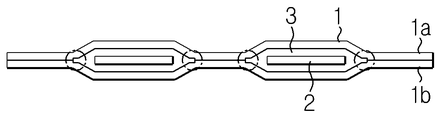
도 1을 참조하면, 파우치형 이차전지는 파우치 케이스(1) 내에 전극 조립체를 수용하고, 전극 조립체의 전극 탭 부분에 연결된 전극 리드(2)가 파우치 케이스(1) 외측으로 인출된 구조를 갖는다.Referring to FIG. 1, the pouch type secondary battery has a structure in which an electrode assembly is housed in a
한편, 상기 파우치형 이차전지에 적용되는 파우치 케이스(1)는 통상 상부 케이스(1a)와 하부 케이스(1b)의 테두리 영역(A)이 맞닿은 상태로 열 융착에 의해 밀봉되는데, 이러한 열 융착에 의한 밀봉 시에 파우치 케이스(1)의 내측 면과 전극 리드(2) 사이의 접착력이 떨어져 밀봉성이 저하될 수 있다.Meanwhile, the
이러한 문제를 해결하기 위해 전극 리드(2)가 인출되는 영역에 수지 성분의 실란트(3)를 적용할 수 있다. 즉, 파우치 케이스(1)의 내측 면과 전극 리드(2) 사이에 실란트(3)가 개재된 상태로 파우치 케이스(1) 테두리 영역(A)의 열 융착이 수행됨으로써 전극 리드(2)가 인출되는 영역에서의 밀봉성 저하의 문제를 해결할 수 있다.In order to solve such a problem, the
다만, 종래의 파우치형 이차전지에 있어서, 한 쌍의 전극 리드(2) 각각에 부착된 한 쌍의 실란트(3)는 상호 분리된 형태를 갖는데, 이 경우 도 2에 도시된 바와 같이, 실란트(3)가 개재된 영역과 개재되지 않은 영역의 경계 부분(점선으로 표시된 부분)에서 밀봉성이 저하될 우려가 있어 문제이다.However, in the conventional pouch-type secondary battery, the pair of
본 발명은 상술한 문제점을 고려하여 창안된 것으로서, 파우치형 이차전지에 적용되는 실란트의 적용 구조를 변경함으로써 이차전지의 밀봉성 향상을 도모하고 또한 이러한 실란트 구조가 적용된 전극 리드 어셈블리를 이용함으로써 파우치형 이차전지의 제조 공정 상의 효율을 향상시키는 것을 일 목적으로 한다.SUMMARY OF THE INVENTION The present invention has been made in view of the above problems and it is an object of the present invention to improve the sealing performance of a secondary battery by changing the application structure of a sealant applied to a pouch type secondary battery, And an object of the present invention is to improve efficiency in the manufacturing process of the secondary battery.
다만, 본 발명이 이루고자 하는 기술적 과제는 상술한 과제에 제한되지 않으며, 위에서 언급되지 않은 또 다른 기술적 과제들은 아래에 기재된 발명의 설명으로부터 당업자에게 명확하게 이해될 수 있을 것이다.It is to be understood, however, that the technical scope of the present invention is not limited to the above-mentioned problems, and other technical subjects not mentioned above can be understood by those skilled in the art from the description of the invention described below.
상기 기술적 과제를 달성하기 위한 본 발명의 일 실시예에 따른 파우치형 이차전지는, 전극 조립체; 상기 전극 조립체와 연결되는 한 쌍의 전극 리드; 상기 전극 조립체를 수용하며 상기 한 쌍의 전극 리드가 외부로 인출된 상태로 밀봉되는 파우치 케이스; 및 상기 전극 리드와 파우치 케이스의 내측 면 사이에 개재되는 실란트; 를 포함하는 것으로서, 상기 실란트는, 상기 파우치 케이스의 폭 방향 일측 단부로부터 타측 단부까지 연속적으로 형성된다.According to an aspect of the present invention, there is provided a pouch type secondary battery including: an electrode assembly; A pair of electrode leads connected to the electrode assembly; A pouch case housing the electrode assembly and being sealed in a state in which the pair of electrode leads are drawn out to the outside; A sealant interposed between the electrode lead and the inner surface of the pouch case; Wherein the sealant is continuously formed from one end to the other end in the width direction of the pouch case.
상기 실란트는, 상기 전극 리드와 대응되는 영역의 두께가 나머지 영역의 두께보다 더 두껍게 형성될 수 있다.The sealant may be formed such that the thickness of the region corresponding to the electrode lead is larger than the thickness of the remaining region.
상기 실란트는, 상기 전극 리드와 대응되는 영역 및 상기 한 쌍의 전극 리드 사이에 위치한 영역의 두께가 상기 한 쌍의 전극 리드의 외측에 위치한 영역의 두께보다 더 두껍게 형성될 수 있다.The sealant may be formed such that a thickness of a region corresponding to the electrode lead and a region located between the pair of electrode leads is larger than a thickness of a region located outside the pair of electrode leads.
상기 실란트는, 상기 파우치 케이스의 폭 방향 일측 단부로부터 타측 단부에 이르기까지 일정한 두께로 형성될 수 있다.The sealant may be formed to have a constant thickness from one end in the width direction to the other end of the pouch case.
상기 실란트는, 상기 전극 리드의 상부에 부착되는 제1 실란트; 및 상기 전극 리드의 하부에 부착되는 제2 실란트를 포함할 수 있다.The sealant comprising: a first sealant attached to an upper portion of the electrode lead; And a second sealant attached to the lower portion of the electrode lead.
또한, 상술한 기술적 과제는 본 발명의 일 실시예에 따른 전극 리드 어셈블리에 의해서도 달성 가능한데, 이러한 본 발명의 일 실시예에 따른 전극 리드 어셈블리는, 전극 조립체에 연결되는 것으로서, 서로 이격되어 나란히 연장된 한 쌍의 전극 리드; 및 상기 전극 조립체를 수용하는 파우치 케이스의 내측 면과 상기 전극 리드 사이에 개재되는 것으로서, 상기 파우치 케이스의 폭 방향 일측 단부로부터 타측 단부에 이르는 길이를 가지며 연속적으로 형성되는 실란트;를 포함한다.The electrode lead assembly according to an embodiment of the present invention is connected to an electrode assembly and is spaced apart from the electrode assembly and extending in parallel to each other. A pair of electrode leads; And a sealant interposed between an inner surface of the pouch case housing the electrode assembly and the electrode lead, the sealant having a length extending from one end of the pouch case in the width direction to the other end thereof.
한편, 상술한 본 발명의 일 실시예에 따른 파우치형 이차전지를 제조하기 위한 본 발명의 일 실시예에 따른 파우치형 이차전지의 제조 방법은, (a) 제6항 내지 제10항 중 어느 한 항에 따른 전극 리드 어셈블리를 제작하는 단계; (b) 전극 리드 어셈블리에 구비된 전극 리드가 전극 조립체에 구비된 전극 탭에 접촉하도록 전극 리드 어셈블리를 안착시키는 단계; (c) 전극 리드를 전극 탭에 용접시키는 단계; 및 (d) 파우치 케이스를 실링하는 단계;를 포함하며,According to another aspect of the present invention, there is provided a method for manufacturing a pouch type secondary battery, the method comprising: (a) forming a pouch type secondary battery according to any one of claims 6 to 10, Manufacturing an electrode lead assembly according to the present invention; (b) seating the electrode lead assembly such that the electrode leads provided on the electrode lead assembly come into contact with electrode tabs provided on the electrode assembly; (c) welding the electrode leads to the electrode tabs; And (d) sealing the pouch case,
상기 (a)단계는, (a1) 한 쌍의 전극 리드가 상호 이격된 상태로 나란하도록 배치하는 단계; 및 (a2) 한 쌍의 전극 리드의 양 면에 각각 제1 실란트 및 제2 실란트를 부착하는 단계;를 포함할 수 있다.The step (a) includes the steps of: (a1) disposing a pair of electrode leads so as to be spaced apart from each other; And (a2) attaching a first sealant and a second sealant on both sides of the pair of electrode leads, respectively.
본 발명에 따르면, 파우치형 이차전지에 적용되는 실란트 구조의 변경을 통해 이차전지의 밀봉성을 향상시킬 수 있고, 또한 이처럼 변경된 구조를 갖는 실란트가 적용된 전극 리드 어셈블리를 이용함으로써 이차전지의 제조 공정 상의 효율을 향상시킬 수 있다.According to the present invention, it is possible to improve the sealability of the secondary battery by changing the sealant structure applied to the pouch-type secondary battery, and by using the electrode lead assembly to which the sealant having such a modified structure is applied, The efficiency can be improved.
본 명세서에 첨부되는 다음의 도면들은 본 발명의 바람직한 실시예를 예시하는 것이며, 후술되는 발명의 상세한 설명과 함께 본 발명의 기술사상을 더욱 이해시키는 역할을 하는 것이므로, 본 발명은 그러한 도면에 기재된 사항에만 한정되어 해석되어서는 아니 된다.
도 1은 종래의 파우치형 이차전지를 나타내는 평면도이다.
도 2는 도 1에 도시된 파우치형 이차전지를 나타내는 정면도이다.
도 3은 본 발명의 일 실시예에 따른 파우치형 이차전지를 나타내는 평면도이다.
도 4는 본 발명의 일 실시예에 따른 파우치형 이차전지에 적용되는 전극 리드 어셈블리를 나타내는 사시도이다.
도 5 내지 도 7은 본 발명의 일 실시예에 따른 전극 리드 어셈블리를 나타내는 정면도이다.
도 8은 본 발명의 일 실시예에 따른 파우치형 이차전지의 제조 방법을 나타내는 순서도이다.BRIEF DESCRIPTION OF THE DRAWINGS The accompanying drawings, which are incorporated in and constitute a part of the specification, illustrate preferred embodiments of the invention and, together with the description of the invention given below, serve to further the understanding of the technical idea of the invention. And should not be construed as limiting.
1 is a plan view showing a conventional pouch type secondary battery.
2 is a front view showing the pouch type secondary battery shown in Fig.
3 is a plan view of a pouch type secondary battery according to an embodiment of the present invention.
4 is a perspective view illustrating an electrode lead assembly applied to a pouch type secondary battery according to an embodiment of the present invention.
5 to 7 are front views illustrating an electrode lead assembly according to an embodiment of the present invention.
8 is a flowchart illustrating a method of manufacturing a pouch type secondary battery according to an embodiment of the present invention.
이하, 첨부된 도면을 참조하여 본 발명의 바람직한 실시예를 상세히 설명하기로 한다. 이에 앞서, 본 명세서 및 청구범위에 사용된 용어나 단어는 통상적이거나 사전적인 의미로 한정해서 해석되어서는 아니 되며, 발명자는 그 자신의 발명을 가장 최선의 방법으로 설명하기 위해 용어의 개념을 적절하게 정의할 수 있다는 원칙에 입각하여 본 발명의 기술적 사상에 부합하는 의미와 개념으로 해석되어야만 한다. 따라서, 본 명세서에 기재된 실시예와 도면에 도시된 구성은 본 발명의 가장 바람직한 일부 실시예에 불과할 뿐이고 본 발명의 기술적 사상을 모두 대변하는 것은 아니므로, 본 출원시점에 있어서 이들을 대체할 수 있는 다양한 균등물과 변형예들이 있을 수 있음을 이해하여야 한다.Hereinafter, preferred embodiments of the present invention will be described in detail with reference to the accompanying drawings. Prior to this, terms and words used in the present specification and claims should not be construed as limited to ordinary or dictionary terms, and the inventor should appropriately interpret the concepts of the terms appropriately It should be construed in accordance with the meaning and concept consistent with the technical idea of the present invention based on the principle that it can be defined. Therefore, the embodiments described in the present specification and the configurations shown in the drawings are only some of the most preferred embodiments of the present invention and do not represent all the technical ideas of the present invention. Therefore, It is to be understood that equivalents and modifications are possible.
먼저, 도 3을 참조하여 본 발명의 일 실시예에 따른 파우치형 이차전지(10)의 전체적인 구성을 설명하기로 한다.First, referring to FIG. 3, the overall structure of a pouch type secondary battery 10 according to an embodiment of the present invention will be described.
도 3은 본 발명의 일 실시예에 따른 파우치형 이차전지를 나타내는 평면도이다.3 is a plan view of a pouch type secondary battery according to an embodiment of the present invention.
도 3을 참조하면, 본 발명의 일 실시예에 따른 파우치형 이차전지는 전극 조립체(미도시), 한 쌍의 전극 리드(12), 실란트(13) 및 파우치 케이스(14)를 포함한다.Referring to FIG. 3, the pouch type secondary battery according to an embodiment of the present invention includes an electrode assembly (not shown), a pair of electrode leads 12, a
상기 전극 조립체(미도시)는 양극 판 및 음극 판 사이에 세퍼레이터가 개재된 형태로 구현된다. 상기 양극 판은 통상 알루미늄(Al) 재질의 집전 판에 양극 활물질이 도포되어 형성되며, 음극 판은 구리(Cu) 재질의 집전 판에 음극 활물질이 도포되어 형성된다.The electrode assembly (not shown) is realized by interposing a separator between the anode plate and the cathode plate. The positive electrode plate is formed by applying a positive electrode active material to a collector plate made of an aluminum material and the negative electrode plate is formed by applying a negative electrode active material to a collector plate made of copper.
이러한 양극 판과 음극 판은 각각 전극 활물질이 도포되지 않은 양극 무지부 및 음극 무지부를 갖는데, 이러한 무지부는 전극 리드(12)와 연결되는 양극 탭 및 음극 탭으로 이용된다.The positive electrode plate and the negative electrode plate have a positive electrode uncoated portion and a negative electrode uncoated portion which are not coated with the electrode active material, respectively. These uncoated portions are used as a positive electrode tab and a negative electrode tab connected to the
상기 전극 리드(12)는 얇은 판상의 금속으로서 전극 조립체에 구비된 전극 탭에 부착되어 전극 조립체의 외측 방향으로 연장된다. 본 발명에 있어서, 상기 한 쌍의 전극 리드(12)는 각각 그 일측이 양극 탭 및 음극 탭에 부착되어 상호 이격된 상태로 나란한 방향을 따라 연장된다.The
한편, 상기 전극 리드(12)는 서로 그 재질이 다를 수 있다. 즉, 상기 전극 리드(12) 중 양극 탭에 연결되는 양극 리드는 양극 판과 동일한 알루미늄 재질로 이루어지고, 음극 탭에 연결되는 음극 리드는 음극 판과 동일한 구리 재질 또는 니켈(Ni)이 코팅된 구리 재질로 이루어질 수 있다.Meanwhile, the electrode leads 12 may be made of different materials. That is, the positive electrode lead connected to the positive electrode tab of the
상기 실란트(13)는 전극 리드(12)와 파우치 케이스(14)의 내측 면 사이에 개재되는 것으로서, 절연성 및 열 융착성을 갖는 필름으로 이루어질 수 있다.The
상기 실란트(13)는 예를 들어 폴리이미드(PI: polyimide), 폴리프로필렌(PP: polyprophylene), 폴리에틸렌(PE: polyethylene) 및 폴리에틸렌 테레프탈레이트(PET: polyethylene terephthalate) 등으로부터 선택된 어느 하나 이상의 물질 층(단일 막 또는 다중 막)으로 이루어질 수 있다. 상기 실란트(13)는 전극 리드(12)와 파우치 케이스(14)의 금속 층 사이에서 단락이 발생하는 것을 방지할 뿐만 아니라 파우치 케이스(14)의 밀봉력을 향상시키는 역할을 한다.The
상기 실란트(13)의 구체적인 구조, 그리고 전극 리드(12) 및 파우치 케이스(14)와의 결합 관계 등에 대한 구체적인 설명은 도 4 내지 도 7을 참조하여 상세히 후술하기로 한다.The detailed structure of the
상기 파우치 케이스(14)는 내측 면에 열 접착 층이 형성된 알루미늄 파우치 필름으로 이루어질 수 있다. 상기 파우치 케이스(14)는 전극 리드(12)가 외부로 인출되도록 전극 조립체를 수용한 채로 테두리 영역(S)이 열 융착됨으로써 밀봉된다. 즉, 상기 파우치 케이스(14)는 상/하 케이스로 구성될 수 있는데, 상/하 케이스의 테두리 부분의 내측 면이 서로 맞닿은 상태에서 열이 가해짐으로써 상/하 케이스가 상호 융착되어 밀봉되는 것이다.The
한편, 밀봉된 파우치 케이스(14) 내에는 이차전지의 종류에 따라 액체, 고체 또는 겔형 등의 전해질(미도시)이 충진된다.On the other hand, an electrolyte (not shown) such as liquid, solid or gel is filled in the sealed
다음은, 도 3과 함께 도 4 내지 도 7을 참조하여 본 발명의 일 실시예에 따른 전극 리드 어셈블리를 설명하기로 한다.Next, an electrode lead assembly according to an embodiment of the present invention will be described with reference to FIG. 3 and FIG. 4 to FIG.
도 4는 본 발명의 일 실시예에 따른 파우치형 이차전지에 적용되는 전극 리드 어셈블리를 나타내는 사시도이고, 도 5 내지 도 7은 본 발명의 일 실시예에 따른 전극 리드 어셈블리를 나타내는 정면도이다.FIG. 4 is a perspective view of an electrode lead assembly applied to a pouch type secondary battery according to an embodiment of the present invention, and FIGS. 5 to 7 are front views illustrating an electrode lead assembly according to an embodiment of the present invention.
먼저, 도 4를 참조하면, 본 발명의 일 실시예에 따른 전극 리드 어셈블리는 앞서 설명한 파우치형 이차전지에 적용되는 한 쌍의 전극 리드(12) 및 실란트(13)로 구성된다.Referring to FIG. 4, an electrode lead assembly according to an embodiment of the present invention includes a pair of electrode leads 12 and a
상기 전극 리드 어셈블리에 있어서, 실란트(13)는 서로 나란하게 배치된 한 쌍의 전극 리드(12)의 상부에 부착되는 제1 실란트(13a) 및 하부에 부착되는 제2 실란트(13b)를 포함하는 형태로 구현될 수 있다. 이 경우, 한 쌍의 전극 리드(12) 사이에 위치한 영역 및 한 쌍의 전극 리드(12)의 외측에 위치한 영역에서 한 쌍의 실란트(13a,13b)는 상호 접착되어 일체로 된 하나의 실란트(13)를 이룬다.In the electrode lead assembly, the
물론, 상기 실란트(13)가 두 개의 부분이 합쳐져 형성되는 것이 아니라, 일체로 형성된 하나의 조각으로 이루어질 수도 있으며, 이 경우 실란트(13)는 전극 리드(12)가 삽입될 수 있도록 전극 리드(12)에 대응되는 한 쌍의 홀을 구비하게 된다.In this case, the
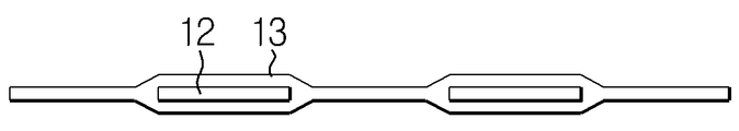
도 3 및 도 4를 함께 참조하면, 상기 실란트(13)는 파우치 케이스(14)의 폭 방향(도 3을 기준으로 볼 때, 좌/우 방향을 의미하는 것으로서 이하 동일함)을 따라 연속적으로 형성된다. 즉, 상기 실란트(13)는 파우치 케이스(14)의 폭 방향 일측 단부로부터 타측 단부에 이르는 길이를 가지고 연속적으로 형성되며, 이로써 전극 리드(12)가 인출되는 영역에 있어서 파우치 케이스(14)의 밀봉력이 취약해지는 것을 방지할 수 있다.3 and 4, the
도 5를 참조하면, 상기 실란트(13)는 전극 리드(12)와 대응되는 영역에서의 두께가 나머지 영역에서의 두께, 즉 한 쌍의 전극 리드(12) 사이에 위치한 영역 및 한 쌍의 전극 리드(12) 각각의 외측에 위치한 영역에서의 두께보다 더 두껍게 형성될 수 있다.5, the
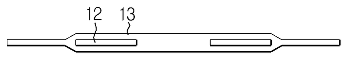
또한, 도 6을 참조하면, 도 5의 경우와는 달리, 상기 실란트(13)는 전극 리드(12)와 대응되는 영역(이하, 제1 영역이라 칭함)에서의 두께 및 한 쌍의 전극 리드(12) 사이에 위치한 영역(이하, 제2 영역이라 칭함)에서의 두께가 한 쌍의 전극 리드(12) 각각의 외측에 위치한 영역(이하, 제3 영역이라 칭함)에서의 두께보다 더 두껍게 형성될 수 있다.6, the
이처럼, 상기 실란트(13)가 제1 영역 및 제2 영역에서 두께 차이를 나타내지 않는 경우, 파우치 케이스(14)가 제1 영역 및 제2 영역 사이를 지날 때 굴곡진 형상을 갖지 않게 되므로 밀봉성이 좀 더 향상될 수 있다.When the
한편, 도 7을 참조하면, 도 5 및 도 6의 경우와는 달리, 상기 실란트(13)는 파우치 케이스(14)의 폭 방향 일측 단부로부터 타측 단부에 이르기까지, 즉 제1 영역, 제2 영역 및 제3 영역 전체에 걸쳐서 일정한 두께로 형성될 수도 있다.5 and 6, the
이처럼, 상기 실란트(13)가 모든 영역에 걸쳐서 일정한 두께를 갖는 경우, 실란트(13)에 부착되는 파우치 케이스(14)의 굴곡이 발생되지 않으므로 밀봉성을 극대화할 수 있게 된다.In this way, when the
상술한 바와 같이, 본 발명의 일 실시예에 따른 파우치형 이차전지는, 실란트(13)가 파우치 케이스(14)의 폭 방향을 따라 실링 영역 전체에 걸쳐서 상/하 파우치 케이스(14a,14b) 사이에 개재된 구조를 가짐으로써 밀봉성을 크게 향상시킬 수 있다.As described above, in the pouch type secondary battery according to the embodiment of the present invention, the
또한, 본 발명의 일 실시예에 따른 파우치형 이차전지의 구조에 따르면, 전극 리드(12)에 실란트(13)를 부착하는 과정이 간소화 되고, 이로써 제작된 전극 리드 어셈블리를 이용함으로써 전극 리드(12)를 전극 탭에 용접하는 공정 역시 편리해 질 수 있어 공정성이 크게 향상될 수 있다.According to the structure of the pouch type secondary battery according to the embodiment of the present invention, the process of attaching the
다음은, 도 8을 참조하여 본 발명의 일 실시예에 따른 파우치형 이차전지의 제조 방법을 설명하기로 한다.Hereinafter, a method of manufacturing a pouch type secondary battery according to an embodiment of the present invention will be described with reference to FIG.
도 8은 본 발명의 일 실시예에 따른 파우치형 이차전지의 제조 방법을 나타내는 순서도이다.8 is a flowchart illustrating a method of manufacturing a pouch type secondary battery according to an embodiment of the present invention.
도 8을 참조하면, 본 발명의 일 실시예에 따른 파우치형 이차전지의 제조 방법은 (a) 전극 리드 어셈블리를 제작하는 단계, (b) 전극 리드 어셈블리를 안착시키는 단계, (c) 전극 리드를 용접하는 단계 및 (d) 파우치 케이스를 실링 하는 단계를 포함한다.Referring to FIG. 8, a method of manufacturing a pouch type secondary battery according to an embodiment of the present invention includes the steps of (a) fabricating an electrode lead assembly, (b) seating the electrode lead assembly, (c) And (d) sealing the pouch case.
상기 (a)단계는, 앞서 설명한 본 발명의 일 실시예에 따른 전극 리드 어셈블리를 제작하는 단계로서, 한 쌍의 전극 리드(12)를 한꺼번에 감싸고, 또한 파우치 케이스(14)의 폭 방향 길이와 동등한 길이를 갖는 실란트(13)를 적용하여 전극 리드 어셈블리를 제작하는 단계에 해당한다.The step (a) is a step of manufacturing the electrode lead assembly according to one embodiment of the present invention, in which the pair of electrode leads 12 are wrapped at a time, and the length of the
좀 더 구체적으로, 상기 (a)단계는, (a1) 한 쌍의 전극 리드(12)가 상호 이격된 상태로 나란하도록 배치하는 단계 및 (a2) 한 쌍의 전극 리드(12)의 양 면에 각각 제1 실란트(13a) 및 제2 실란트(13b)를 부착하는 단계를 포함할 수 있다.More specifically, the step (a) includes: (a1) arranging the pair of electrode leads 12 so as to be spaced apart from each other; and (a2) And attaching the
상기 (b)단계는, 제작된 상기 전극 리드 어셈블리에 구비된 전극 리드(12)가 전극 조립체에 구비된 전극 탭에 접촉하도록 전극 리드 어셈블리를 안착시키는 단계이다.In the step (b), the electrode lead assembly of the manufactured electrode lead assembly is brought into contact with the electrode tab of the electrode assembly.
상기 (c)단계는, 전극 리드(12)가 전극 조립체와 전기적으로 연결될 수 있도록 전극 조립체에 구비된 전극 탭에 용접을 시행하는 단계이다.In the step (c), the electrode tabs of the electrode assembly are welded so that the electrode leads 12 can be electrically connected to the electrode assembly.
상기 (d)단계는, 용접에 의해 전극 조립체와 연결된 전극 리드(12)가 외부로 인출된 상태로 파우치 케이스(14)의 테두리 영역(S)을 열 융착함으로써 파우치 케이스(14)를 밀봉하는 단계이다.The step (d) includes sealing the
본 발명의 일 실시예에 따른 파우치형 이차전지의 제조 방법에 따르면, 전극 리드(12)에 실란트(13)를 부착하는 공정이 간소화 되고, 또한 이로써 제작된 전극 리드 어셈블리를 이용함으로써 전극 리드(12)를 전극 탭에 용접하는 공정 역시 편리해질 수 있어 파우치형 이차전지의 제조 공정상의 효율을 향상시킬 수 있다.According to the method of manufacturing a pouch type secondary battery according to an embodiment of the present invention, the process of attaching the
이상에서 본 발명은 비록 한정된 실시예와 도면에 의해 설명되었으나, 본 발명은 이것에 의해 한정되지 않으며 본 발명이 속하는 기술분야에서 통상의 지식을 가진 자에 의해 본 발명의 기술사상과 아래에 기재될 특허청구범위의 균등범위 내에서 다양한 수정 및 변형이 가능함은 물론이다.While the present invention has been particularly shown and described with reference to exemplary embodiments thereof, it is to be understood that the invention is not to be limited to the details thereof and that various changes and modifications will be apparent to those skilled in the art. And various modifications and variations are possible within the scope of the appended claims.
12: 전극 리드
13: 실란트
13a: 제1 실란트
13b: 제2 실란트
14: 파우치 케이스
S: 테두리 영역12: electrode lead 13: sealant
13a:
14: Pouch case S: Rim area
Claims (12)
상기 실란트는, 상기 파우치 케이스의 폭 방향 일측 단부로부터 타측 단부까지 연속적으로 형성되는 것을 특징으로 하는 파우치형 이차전지.An electrode assembly; A pair of electrode leads connected to the electrode assembly; A pouch case housing the electrode assembly and being sealed in a state in which the pair of electrode leads are drawn out to the outside; A sealant interposed between the electrode lead and the inner surface of the pouch case; The pouch type secondary battery according to claim 1,
Wherein the sealant is continuously formed from one end portion in the width direction of the pouch case to the other end portion of the pouch case.
상기 실란트는,
상기 전극 리드와 대응되는 영역의 두께가 나머지 영역의 두께보다 더 두껍게 형성된 것을 특징으로 하는 파우치형 이차전지.The method according to claim 1,
The sealant,
Wherein a thickness of the region corresponding to the electrode lead is greater than a thickness of the remaining region.
상기 실란트는,
상기 전극 리드와 대응되는 영역 및 상기 한 쌍의 전극 리드 사이에 위치한 영역의 두께가 상기 한 쌍의 전극 리드의 외측에 위치한 영역의 두께보다 더 두껍게 형성된 것을 특징으로 하는 파우치형 이차전지.The method according to claim 1,
The sealant,
Wherein a thickness of a region corresponding to the electrode lead and a region located between the pair of electrode leads is greater than a thickness of a region located outside the pair of electrode leads.
상기 실란트는,
상기 파우치 케이스의 폭 방향 일측 단부로부터 타측 단부에 이르기까지 일정한 두께로 형성된 것을 특징으로 하는 파우치형 이차전지.The method according to claim 1,
The sealant,
Wherein the pouch case is formed to have a constant thickness from one end of the pouch case in the width direction to the other end thereof.
상기 실란트는,
상기 전극 리드의 상부에 부착되는 제1 실란트; 및
상기 전극 리드의 하부에 부착되는 제2 실란트를 포함하는 것을 특징으로 하는 파우치형 이차전지.The method according to claim 1,
The sealant,
A first sealant attached to an upper portion of the electrode lead; And
And a second sealant attached to a lower portion of the electrode lead.
상기 전극 조립체를 수용하는 파우치 케이스의 내측 면과 상기 전극 리드 사이에 개재되는 것으로서, 상기 파우치 케이스의 폭 방향 일측 단부로부터 타측 단부에 이르는 길이를 가지며 연속적으로 형성되는 실란트;
를 포함하는 전극 리드 어셈블리.A pair of electrode leads connected to the electrode assembly and extending in parallel to each other; And
A sealant interposed between an inner surface of the pouch case housing the electrode assembly and the electrode lead, the sealant having a length extending from one end of the pouch case in the width direction to the other end thereof;
And an electrode lead assembly.
상기 실란트는,
상기 전극 리드와 대응되는 영역의 두께가 나머지 영역의 두께보다 더 두껍게 형성된 것을 특징으로 하는 전극 리드 어셈블리.The method according to claim 6,
The sealant,
Wherein a thickness of the region corresponding to the electrode lead is greater than a thickness of the remaining region.
상기 실란트는,
상기 전극 리드와 대응되는 영역 및 상기 한 쌍의 전극 리드 사이에 위치한 영역의 두께가 상기 한 쌍의 전극 리드의 외측에 위치한 영역의 두께보다 더 두껍게 형성된 것을 특징으로 하는 전극 리드 어셈블리.The method according to claim 6,
The sealant,
Wherein a thickness of a region corresponding to the electrode lead and a region located between the pair of electrode leads is greater than a thickness of a region located outside the pair of electrode leads.
상기 실란트는,
상기 파우치 케이스의 폭 방향 일측 단부로부터 타측 단부에 이르기까지 일정한 두께로 형성된 것을 특징으로 하는 전극 리드 어셈블리.The method according to claim 6,
The sealant,
Wherein the pouch case is formed to have a constant thickness from one end of the pouch case in the width direction to the other end thereof.
상기 실란트는,
상기 전극 리드의 상부에 부착되는 제1 실란트; 및
상기 전극 리드의 하부에 부착되는 제2 실란트를 포함하는 것을 특징으로 하는 전극 리드 어셈블리.The method according to claim 6,
The sealant,
A first sealant attached to an upper portion of the electrode lead; And
And a second sealant attached to a lower portion of the electrode lead.
(b) 전극 리드 어셈블리에 구비된 전극 리드가 전극 조립체에 구비된 전극 탭에 접촉하도록 전극 리드 어셈블리를 안착시키는 단계;
(c) 전극 리드를 전극 탭에 용접시키는 단계; 및
(d) 파우치 케이스를 실링하는 단계;
를 포함하는 파우치형 이차전지의 제조 방법.(a) fabricating the electrode lead assembly according to any one of claims 6 to 10;
(b) seating the electrode lead assembly such that the electrode leads provided on the electrode lead assembly come into contact with electrode tabs provided on the electrode assembly;
(c) welding the electrode leads to the electrode tabs; And
(d) sealing the pouch case;
Wherein the pouch-shaped secondary battery includes a plurality of pouch-shaped secondary batteries.
상기 (a)단계는,
(a1) 한 쌍의 전극 리드가 상호 이격된 상태로 나란하도록 배치하는 단계; 및
(a2) 한 쌍의 전극 리드의 양 면에 각각 제1 실란트 및 제2 실란트를 부착하는 단계;
를 포함하는 것을 특징으로 하는 파우치형 이차전지의 제조 방법.12. The method of claim 11,
The step (a)
(a1) arranging a pair of electrode leads so as to be spaced apart from each other; And
(a2) attaching a first sealant and a second sealant to both sides of a pair of electrode leads;
The method of manufacturing a pouch type secondary battery according to claim 1,
Priority Applications (1)
| Application Number | Priority Date | Filing Date | Title |
|---|---|---|---|
| KR1020140150447A KR101769106B1 (en) | 2014-10-31 | 2014-10-31 | A pouch type secondary battery and a electrode lead assembly applied for the same |
Applications Claiming Priority (1)
| Application Number | Priority Date | Filing Date | Title |
|---|---|---|---|
| KR1020140150447A KR101769106B1 (en) | 2014-10-31 | 2014-10-31 | A pouch type secondary battery and a electrode lead assembly applied for the same |
Publications (2)
| Publication Number | Publication Date |
|---|---|
| KR20160051060A true KR20160051060A (en) | 2016-05-11 |
| KR101769106B1 KR101769106B1 (en) | 2017-08-17 |
Family
ID=56025900
Family Applications (1)
| Application Number | Title | Priority Date | Filing Date |
|---|---|---|---|
| KR1020140150447A KR101769106B1 (en) | 2014-10-31 | 2014-10-31 | A pouch type secondary battery and a electrode lead assembly applied for the same |
Country Status (1)
| Country | Link |
|---|---|
| KR (1) | KR101769106B1 (en) |
Cited By (1)
| Publication number | Priority date | Publication date | Assignee | Title |
|---|---|---|---|---|
| KR20190059677A (en) * | 2017-11-23 | 2019-05-31 | 주식회사 엘지화학 | The Pouch Type Secondary Battery |
Family Cites Families (1)
| Publication number | Priority date | Publication date | Assignee | Title |
|---|---|---|---|---|
| KR100917734B1 (en) | 2007-07-19 | 2009-09-21 | 삼성에스디아이 주식회사 | Pouch Type Lithium Secondary Battery |
-
2014
- 2014-10-31 KR KR1020140150447A patent/KR101769106B1/en active IP Right Grant
Cited By (1)
| Publication number | Priority date | Publication date | Assignee | Title |
|---|---|---|---|---|
| KR20190059677A (en) * | 2017-11-23 | 2019-05-31 | 주식회사 엘지화학 | The Pouch Type Secondary Battery |
Also Published As
| Publication number | Publication date |
|---|---|
| KR101769106B1 (en) | 2017-08-17 |
Similar Documents
| Publication | Publication Date | Title |
|---|---|---|
| JP5214543B2 (en) | Secondary battery | |
| US9077027B2 (en) | Electrode assembly and secondary battery using the same | |
| JP6315572B2 (en) | Electrochemical cell | |
| KR102058194B1 (en) | battery module | |
| KR101735512B1 (en) | Secondary battery with improved structure of electrode lead and Method for manufacturing the same | |
| KR20140094205A (en) | Rechargeable battery | |
| KR20160134331A (en) | Pouch type secondary battery and method for fabricating the same | |
| KR101658973B1 (en) | Pouch type secondary battery and secondary battery module comprising the same | |
| KR20150043093A (en) | Electrode lead and secondary battery comprising the same | |
| JP2006164784A (en) | Film-armored electric device | |
| KR20150050212A (en) | Battery cell with patterned shape and Method for manufacturing the same | |
| US11114712B2 (en) | Battery module having improved cooling structure | |
| KR100879895B1 (en) | Secondary Battery Having Improved Sealing Property at Heat-melted Portion of Case | |
| KR101606461B1 (en) | Secondary battery module and pouch type secondary battery | |
| KR102504792B1 (en) | Rechargeable battery | |
| KR20160002176A (en) | Secondary battery | |
| KR101658961B1 (en) | Pouch type secondary battery | |
| KR101769106B1 (en) | A pouch type secondary battery and a electrode lead assembly applied for the same | |
| US20130266850A1 (en) | Electrochemical cell and method for manufacturing same | |
| KR20170112394A (en) | Secondary Battery And Manufacture Method | |
| KR100890160B1 (en) | Secondary Battery Having Improved Sealing Property at Heat-melted Portion of Case | |
| KR101621591B1 (en) | asymmetric electrode plate, asymmetric electrode assembly having asymmetric electrode plate, and asymmetric secondary battery having asymmetric electrode assembly | |
| KR101662640B1 (en) | Secondary battery with improved tab-lead coupling structure | |
| KR20170050445A (en) | Pouch type secondary battery | |
| JP5650567B2 (en) | Flat battery and sealed can |
Legal Events
| Date | Code | Title | Description |
|---|---|---|---|
| A201 | Request for examination | ||
| E902 | Notification of reason for refusal | ||
| E701 | Decision to grant or registration of patent right | ||
| GRNT | Written decision to grant |