KR20160050737A - Camera Module - Google Patents
Camera Module Download PDFInfo
- Publication number
- KR20160050737A KR20160050737A KR1020140149620A KR20140149620A KR20160050737A KR 20160050737 A KR20160050737 A KR 20160050737A KR 1020140149620 A KR1020140149620 A KR 1020140149620A KR 20140149620 A KR20140149620 A KR 20140149620A KR 20160050737 A KR20160050737 A KR 20160050737A
- Authority
- KR
- South Korea
- Prior art keywords
- lens
- ring gear
- cover
- wiper
- camera module
- Prior art date
- Legal status (The legal status is an assumption and is not a legal conclusion. Google has not performed a legal analysis and makes no representation as to the accuracy of the status listed.)
- Granted
Links
- 238000000034 method Methods 0.000 claims description 8
- 239000000463 material Substances 0.000 claims description 4
- 239000000126 substance Substances 0.000 description 6
- 230000000694 effects Effects 0.000 description 5
- 239000000356 contaminant Substances 0.000 description 3
- 230000002411 adverse Effects 0.000 description 1
- 239000000428 dust Substances 0.000 description 1
- 238000012986 modification Methods 0.000 description 1
- 230000004048 modification Effects 0.000 description 1
- 230000001151 other effect Effects 0.000 description 1
- 230000002093 peripheral effect Effects 0.000 description 1
- 239000004071 soot Substances 0.000 description 1
Images


Classifications
-
- B—PERFORMING OPERATIONS; TRANSPORTING
- B60—VEHICLES IN GENERAL
- B60S—SERVICING, CLEANING, REPAIRING, SUPPORTING, LIFTING, OR MANOEUVRING OF VEHICLES, NOT OTHERWISE PROVIDED FOR
- B60S1/00—Cleaning of vehicles
- B60S1/02—Cleaning windscreens, windows or optical devices
- B60S1/56—Cleaning windscreens, windows or optical devices specially adapted for cleaning other parts or devices than front windows or windscreens
- B60S1/566—Cleaning windscreens, windows or optical devices specially adapted for cleaning other parts or devices than front windows or windscreens including wiping devices
-
- G—PHYSICS
- G03—PHOTOGRAPHY; CINEMATOGRAPHY; ANALOGOUS TECHNIQUES USING WAVES OTHER THAN OPTICAL WAVES; ELECTROGRAPHY; HOLOGRAPHY
- G03B—APPARATUS OR ARRANGEMENTS FOR TAKING PHOTOGRAPHS OR FOR PROJECTING OR VIEWING THEM; APPARATUS OR ARRANGEMENTS EMPLOYING ANALOGOUS TECHNIQUES USING WAVES OTHER THAN OPTICAL WAVES; ACCESSORIES THEREFOR
- G03B17/00—Details of cameras or camera bodies; Accessories therefor
- G03B17/56—Accessories
-
- G—PHYSICS
- G02—OPTICS
- G02B—OPTICAL ELEMENTS, SYSTEMS OR APPARATUS
- G02B1/00—Optical elements characterised by the material of which they are made; Optical coatings for optical elements
- G02B1/10—Optical coatings produced by application to, or surface treatment of, optical elements
- G02B1/18—Coatings for keeping optical surfaces clean, e.g. hydrophobic or photo-catalytic films
-
- H—ELECTRICITY
- H04—ELECTRIC COMMUNICATION TECHNIQUE
- H04N—PICTORIAL COMMUNICATION, e.g. TELEVISION
- H04N23/00—Cameras or camera modules comprising electronic image sensors; Control thereof
- H04N23/50—Constructional details
- H04N23/51—Housings
-
- H—ELECTRICITY
- H04—ELECTRIC COMMUNICATION TECHNIQUE
- H04N—PICTORIAL COMMUNICATION, e.g. TELEVISION
- H04N23/00—Cameras or camera modules comprising electronic image sensors; Control thereof
- H04N23/50—Constructional details
- H04N23/55—Optical parts specially adapted for electronic image sensors; Mounting thereof
Landscapes
- Engineering & Computer Science (AREA)
- Physics & Mathematics (AREA)
- Multimedia (AREA)
- Signal Processing (AREA)
- General Physics & Mathematics (AREA)
- Chemical Kinetics & Catalysis (AREA)
- Chemical & Material Sciences (AREA)
- Optics & Photonics (AREA)
- Mechanical Engineering (AREA)
- Studio Devices (AREA)
- Camera Bodies And Camera Details Or Accessories (AREA)
- Lens Barrels (AREA)
- Structure And Mechanism Of Cameras (AREA)
- Accessories Of Cameras (AREA)
Abstract
본 발명은 하우징과, 상기 하우징의 일측을 덮도록 구비되는 커버와, 상기 커버에 구비된 렌즈 및 상기 렌즈의 둘레를 따라 회전하도록 링기어가 구비되고, 상기 링기어를 회전시켜 상기 렌즈의 표면에 이물을 제거하도록 설치된 구동모터;를 포함하는 카메라 모듈에 관한 것이다.According to the present invention, there is provided a zoom lens comprising a housing, a cover provided to cover one side of the housing, a lens provided on the cover, and a ring gear for rotating along the periphery of the lens, And a drive motor installed to remove foreign objects.
Description
본 발명은 카메라 모듈에 관한 것으로, 보다 상세하게는 카메라 렌즈의 이물질을 제거할 수 있는 카메라 모듈에 관한 것이다.
The present invention relates to a camera module, and more particularly, to a camera module capable of removing foreign substances from a camera lens.
일반적으로 차량에는 카메라 모듈이 장착되어 탑승객에게 다양한 사양을 제공하고 있다. 여기서 후방카메라를 예로 들면, 주차보조장치로서 사용되고 있으며, 주차보조장치가 후방차량 접근정보등을 알려 주도록 설정되기도 한다.Generally, the vehicle is equipped with a camera module to provide various specifications to passengers. Here, the rear camera is used as a parking assist device, for example, and the parking assist device is set to inform the rear vehicle access information and the like.
이러한 카메라 모듈은 차량의 외부에 설치되어 차량 외부의 날시 등 외부환경 등에 의한 영향을 받게 된다. 특히 온도의 급격한 변화로 인하여 후방카메라의 외부창 또는 외부렌즈부분에 습기가 발생할 수 있으며, 도로의 먼지 및 매연 등으로 인하여 외부 렌즈부분이 오염되거나, 이물질 등이 렌즈에 안착되어 탑승자에게 명확한 정보를 제공할 수 없게 된다.Such a camera module is installed outside the vehicle and is influenced by an external environment such as a fly outside the vehicle. Particularly, due to a sudden change in temperature, moisture may be generated in the outer window of the rear camera or in the outer lens portion, and the outer lens portion may be contaminated due to dust on the road or soot, or foreign substances may be seated on the lens to provide clear information to the occupant I can not do it.
이러한, 오염물질등을 제거하고자 탑승자는 차량에서 하차하여 렌즈의 오염물질을 제거하여야 하는 불편함이 있어, 렌즈에 오염물질을 자동으로 제거할 수 있도록 열선을 사용하여 습기를 제거하거나, 압전소자를 이용하여 이물질을 제거하기도 한다. In order to remove such contaminants, the passenger has to get off the vehicle and remove the contaminants from the lens. Therefore, it is necessary to remove moisture using a hot wire to automatically remove contaminants from the lens, It is also possible to remove foreign matter by using it.
그러나 이와 같은 방법에 의하면, 열선에 의해 습기를 제거할 경우 습기제거에 시간이 오래 걸리며, 렌즈에 열이 가해질 경우 악영향을 미칠 수 있는 문제점이 있다.However, according to this method, when the moisture is removed by the heat ray, it takes a long time to remove the moisture, and there is a problem that adverse effect is exerted when heat is applied to the lens.
또, 압전소자를 이용하여 렌즈의 이물질을 제거하는 경우 크기가 작거나 질량이 작으면 제거가 가능하지만 크기가 크고, 질량이 큰 이물질의 경우 제거하기가 힘들며, 압전소자가 작동하는 동안은 진동으로 인하여 화면이 올바르게 나오지 않는 문제점이 있었다.
In addition, when the foreign substance of the lens is removed by using the piezoelectric element, it is possible to remove it if the size is small or the mass is small. However, it is difficult to remove the foreign matter having a large size and a large mass, There is a problem that the screen does not come out correctly.
본 발명이 해결하고자 하는 과제는 렌즈의 이물질등을 빠른시간에 제거함에도 악천후등에서도 카메라의 성능을 유지하도록 하는데 있으며, 렌즈에 안착한 이물질의 크기에 상관없이 제거할 수 있도록 하는데 있다A problem to be solved by the present invention is to maintain the performance of a camera even in a bad weather even if a foreign substance or the like of the lens is removed in a short time, and it is possible to remove the foreign matter regardless of the size of a foreign object seated on the lens
본 발명의 과제들은 이상에서 언급한 과제들로 제한되지 않으며, 언급되지 않은 또 다른 과제들은 아래의 기재로부터 당업자에게 명확하게 이해될 수 있을 것이다.
The problems of the present invention are not limited to the above-mentioned problems, and other problems not mentioned can be clearly understood by those skilled in the art from the following description.
상기 과제를 달성하기 위하여, 본 발명의 실시예에 따른 카메라 모듈은, 하우징과, 상기 하우징을 일측에서 덮도록 구비되는 커버와, 상기 커버에 구비된 렌즈 및 상기 렌즈의 둘레를 따라 회전하도록 링기어가 구비되고, 상기 링기어를 회전시켜 상기 렌즈의 표면에 이물을 제거하도록 설치된 구동모터를 포함한다.According to an aspect of the present invention, there is provided a camera module including a housing, a cover provided to cover the housing from one side, a lens provided on the cover, and a ring gear And a drive motor installed to rotate the ring gear to remove foreign matter from the surface of the lens.
또한, 상기 구동모터가 회전함과 동시에 상기 링기어가 회전하면서 상기 렌즈를 닦도록 구비된 와이퍼를 포함한다.The wiper is provided to wipe the lens while the driving motor rotates and the ring gear rotates.
또한, 상기 와이퍼는 탄성력을 가지는 러버재질로 구비될 수 있다.Further, the wiper may be made of a rubber material having an elastic force.
또한, 상기 커버에는 상기 렌즈가 안착하도록 렌즈안착부가 일부 돌출될 수 있다.Further, the cover may partially protrude the lens seating portion so that the lens is seated.
또한, 상기 구동모터는 상기 커버의 측벽에 설치될 수 있다.Further, the driving motor may be installed on the side wall of the cover.
또한, 상기 구동모터에는 상기 링기어에 구동력을 전달하여 회전시키도록 피니언기어가 구비될 수 있다.In addition, the drive motor may be provided with a pinion gear to transmit and rotate the driving force to the ring gear.
또한, 상기 와이퍼는, 상기 피니언기어에 일측이 고정되도록 설치되고, 타측이 링기어의 기어이에 설치되어 상기 링기어가 회전함으로 상기 피니언기어의 회전력에 의해 상기 와이퍼가 회전할 수 있다.In addition, the wiper may be provided so that one side of the wiper is fixed to the pinion gear, the other side thereof is provided to the gear of the ring gear, and the ring gear is rotated, so that the wiper can be rotated by the rotational force of the pinion gear.
또한, 상기 링기어는 상기 와이퍼가 상기 렌즈의 표면에 접하도록 상기 렌즈안착부의 폭보다 작게 형성될 수 있다.The ring gear may be formed to have a width smaller than the width of the lens seat so that the wiper contacts the surface of the lens.
기타 실시예들의 구체적인 사항들은 상세한 설명 및 도면들에 포함되어 있다.
The details of other embodiments are included in the detailed description and drawings.
본 발명의 카메라 모듈에 따르면 다음과 같은 효과가 하나 혹은 그 이상 있다.According to the camera module of the present invention, one or more of the following effects can be obtained.
첫째로, 본 발명의 카메라 모듈에 따르면, 렌즈에 묻은 습기와 이물질을 지속적으로 또, 신속하게 제거하여 악천후에서도 카메라의 성능을 유지할 수 있는 효과가 있다.First, according to the camera module of the present invention, it is possible to continuously and quickly remove moisture and foreign matter adhering to the lens, thereby maintaining the performance of the camera even in bad weather.
둘째로, 본 발명의 카메라 모듈에 따르면, 렌즈에 질량이 큰 이물질의 제거도 용이하게 할 수 있는 효과가 있다.Secondly, according to the camera module of the present invention, it is possible to easily remove foreign matter having a large mass on the lens.
셋째로, 본 발명의 카메라 모듈에 따르면, 렌즈표면의 이물질이나 습기를 감지하는 제어 프로그램 개발을 하지 않아도 되므로 원가절감이 가능한 효과가 있다.Thirdly, according to the camera module of the present invention, there is no need to develop a control program for detecting foreign matter or moisture on the surface of the lens, thereby reducing the cost.
넷째로, 본 발명의 카메라 모듈에 따르면, 불필요한 에너지를 줄여 에너지 효율을 높일 수 있는 효과가 있다.Fourthly, according to the camera module of the present invention, energy efficiency can be improved by reducing unnecessary energy.
다섯째로, 본 발명의 카메라 모듈에 따르면, 카메라의 화질을 항상 일정하게 확보하여, 운전자의 편의성을 향상시킬 수 있는 효과가 있다.Fifthly, according to the camera module of the present invention, there is an effect that the image quality of the camera is always kept constant and the convenience of the driver can be improved.
본 발명의 효과들은 이상에서 언급한 효과들로 제한되지 않으며, 언급되지 않은 또 다른 효과들은 청구범위의 기재로부터 당업자에게 명확하게 이해될 수 있을 것이다.
The effects of the present invention are not limited to the effects mentioned above, and other effects not mentioned can be clearly understood by those skilled in the art from the description of the claims.
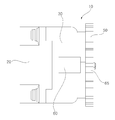
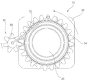
도 1은 본 발명에 따른 카메라 모듈을 나타내는 사시도,
도 2는 도 1에 카메라 모듈의 일측을 나타내는 좌측면도,
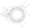
도 3a 내지 3e는 본 발명에 따른 작동순서를 나타내는 정면도이다.1 is a perspective view showing a camera module according to the present invention,
Fig. 2 is a left side view showing one side of the camera module in Fig. 1,
3A to 3E are front views showing an operation sequence according to the present invention.
본 발명의 이점 및 특징, 그리고 그것들을 달성하는 방법은 첨부되는 도면과 함께 상세하게 후술되어 있는 실시예들을 참조하면 명확해질 것이다. 그러나 본 발명은 이하에서 개시되는 실시예들에 한정되는 것이 아니라 서로 다른 다양한 형태로 구현될 수 있으며, 단지 본 실시예들은 본 발명의 개시가 완전하도록 하고, 본 발명이 속하는 기술분야에서 통상의 지식을 가진 자에게 발명의 범주를 완전하게 알려주기 위해 제공되는 것이며, 본 발명은 청구항의 범주에 의해 정의될 뿐이다. 명세서 전체에 걸쳐 동일 참조 부호는 동일 구성 요소를 지칭한다.BRIEF DESCRIPTION OF THE DRAWINGS The advantages and features of the present invention, and the manner of achieving them, will be apparent from and elucidated with reference to the embodiments described hereinafter in conjunction with the accompanying drawings. The present invention may, however, be embodied in many different forms and should not be construed as limited to the embodiments set forth herein. Rather, these embodiments are provided so that this disclosure will be thorough and complete, and will fully convey the scope of the invention to those skilled in the art. To fully disclose the scope of the invention to those skilled in the art, and the invention is only defined by the scope of the claims. Like reference numerals refer to like elements throughout the specification.
이하, 본 발명의 실시예들에 의하여 카메라 모듈을 설명하기 위한 도면들을 참고하여 본 발명에 대해 설명하도록 한다.Hereinafter, the present invention will be described with reference to the drawings for explaining a camera module according to embodiments of the present invention.
바람직한 카메라 모듈은 당해 기술분야에서 통상의 지식을 가진 자에 의해 변경될 수 있으며, 본 발명의 실시예에서는 카메라 모듈인 경우이다.A preferred camera module may be modified by a person skilled in the art and is a camera module in the embodiment of the present invention.
도 1은 본 발명에 따른 카메라 모듈을 나타내는 사시도이고, 도 2는 도 1에 카메라 모듈의 일측을 나타내는 좌측면도이다.FIG. 1 is a perspective view showing a camera module according to the present invention, and FIG. 2 is a left side view showing one side of a camera module in FIG.
본 발명에 따른 카메라 모듈을 도 1 및 도 2를 참조하여 설명하면, 카메라 모듈(10)은 하우징(20)과, 하우징(20)의 일측에서 덮도록 구비된 커버(30)와, 커버(30)에는 렌즈(40), 링기어 및 구동모터(60)를 포함한다.1 and 2, the
하우징(20)은 일측에 부속자재가 수납되도록 개구되고, 타측이 차폐되게 형성된다. 하우징(20)의 일측에서 커버(30)로 덮어 결합된다. 하우징(20)의 타측은 고정되도록 고정부가 형성된다. 하우징(20)과 커버(30)는 고정볼트(25)에 의해 고정된다. 고정볼트(25)는 하우징(20)에 커버(30)가 씌워지는 반대방향에서 체결된다.The
커버(30)는, 하우징(20)의 일측을 덮도록 구비된다. 커버(30)는 중공되어 하우징(20)과 결합되는 타측으로 렌즈(40)가 안착하도록 렌즈안착부가 일부 돌출되게 형성된다. 렌즈(40)는 커버(30)의 내부에서 안착되되, 렌즈안착부와 수평을 이루게 된다.The cover (30) is provided so as to cover one side of the housing (20). The
커버(30)에 형성된 렌즈안착부는 링기어(50)가 회전가능하게 장착되되, 렌즈안착부로부터 이탈을 방지하도록 단부둘레가 링기어(50)를 향하여 돌기가 형성될 수 있다. 돌기는 링기어(50)의 이탈을 방지하도록 단부둘레를 따라 형성될 수 있다.The lens seat portion formed on the
링기어(50)는 렌즈안착부의 외둘레면에 장착된다. 링기어(50)는 렌즈안착부의 외둘레면에서 렌즈(40)의 둘레를 따라 회전한다. 링기어(50)가 렌즈안착부의 외둘레면에서 회전가능하도록 장착된다.The
링기어(50)에는 복수의 기어이가 형성되고, 복수의 기어이 중 적어도 하나에는 렌즈안착부가 돌출된 방향으로 고정돌기(50a)가 형성되어 와이퍼가 설치된다. 링기어(50)는 와이퍼(70)가 렌즈(40)의 표면에 접하도록 렌즈안착부의 돌출된 길이보다 작게 형성되어 후술할 와이퍼(70)가 렌즈면과 접촉하게 된다.A plurality of gear teeth are formed in the
구동모터(60)는 링기어(50)를 회전시켜 렌즈(40)의 표면에 이물을 제거하도록 설치된다. 구동모터(60)는 커버(30)의 측벽에 설치될 수 있다. 구동모터(60)에는 피니언기어(65)가 구비되어 링기어(50)에 구동력을 전달하여 회전시키도록 한다. 피니언기어(65)에는 후술할 와이퍼(70)가 설치되도록 돌기부(65a)가 형성된다. 돌기부(65a)는 구동모터(60) 작동 및 피니언기어(65)의 회전에 의한 영향을 받지 않는다.The
와이퍼(70)는 탄성력을 가지는 러버 재질로 렌즈(40)를 닦도록 구비된다. 와이퍼(70)는 구동모터(60)가 회전함과 동시에 링기어(50)가 회전한다. 따라서, 와이퍼(70)는 링기어(50)가 구동모터(60)에 의해 회전하면 늘어나게 되어 렌즈(40)와 면접된 부분이 렌즈(40)를 닦게 된다. 와이퍼(70)는, 피니언기어(65)에 일측이 고정되도록 설치되고, 타측이 링기어(50)의 복수의 기어이 중 적어도 하나에 설치되어 링기어(50)가 회전함으로 피니언기어(65)의 회전력에 의해 회전한다.The
상기와 같이 구성되는 본 발명에 따른 카메라 모듈의 작용을 설명하면 다음과 같다.The operation of the camera module according to the present invention will now be described.
도 3a 내지 3e는 본 발명에 따른 작동순서를 나타내는 정면도이다.3A to 3E are front views showing an operation sequence according to the present invention.
도 3a 내지 3e를 참조하여 설명하면, 커버(30)의 측벽에는 피니언기어(65)가 설치된 구동모터(60)가 장착된다. 그리고 커버(30)의 렌즈안착부 외둘레에 피니언기어(65)와 기어이가 맞물리도록 링기어(50)가 회전가능하게 설치된다.3A to 3E, a
다음, 와이퍼(70)가 피니언기어(65)의 돌기부(65a)와 링기어(50)의 고정돌기(50a)에 연결되게 설치된다. 와이퍼(70)의 설치시 링기어(50)의 고정돌기(50a)는 피니언기어(65)와 근접하여 와이퍼(70)가 렌즈에 접촉되지 않은 상태에서 설치하는 것이 바람직할 것이다.Next, the
여기서, 링기어(50)는 설계자에 의해 구동모터(60)의 회전방향을 결정하게 되는데, 본 발명에서는 구동모터(60)가 시계방향으로 회전시 링기어(50)는 반시계방향으로 회전하는 것을 기준으로 설명하면, 구동모터(60)가 작동하게 되면, 구동모터(60)와 결합된 피니언기어(65)에서 회전력이 전달되어 링기어(50)가 반시계방향으로 회전하게 된다.Here, the
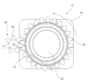
따라서, 렌즈(40)에 이물질이 안착한 경우, 구동모터(60)가 작동하면, 구동모터(60)와 결합된 피니언기어(65)가 시계방향으로 회전하면서 링기어(50)가 반시계방향으로 회전하게 된다. When the driving
이때, 렌즈(40)에 묻은 이물질은 와이퍼(70)가 늘어나면서 링기어(50)의 회전방향으로 렌즈(40)의 표면을 반시계방향으로 움직이며 이물질을 제거한 뒤, 다시 피니언기어(65)와 근접하여 위치하게 된다.At this time, the foreign substances adhering to the
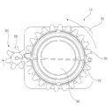
마찬가지로, 링기어(50)를 시계방향으로 회전시키며 렌즈(40) 표면의 이물질을 제거하고자 할 경우에는 피니언기어(65)를 반시계방향으로 회전시킬 수 있도록 구동모터(60)를 구비 및 구동시키면 될 것이므로 이에 대한 상세한 설명은 생략하도록 한다.Similarly, when the
이상에서는 본 발명의 바람직한 실시예에 대하여 도시하고 설명하였지만, 본 발명은 상술한 특정의 실시예에 한정되지 아니하며, 특허청구범위에서 청구하는 본 발명의 요지를 벗어남이 없이 당해 발명이 속하는 기술분야에서 통상의 지식을 가진 자에 의해 다양한 변형실시가 가능한 것은 물론이고, 이러한 변형실시들은 본 발명의 기술적 사상이나 전망으로부터 개별적으로 이해되어서는 안될 것이다.While the present invention has been particularly shown and described with reference to exemplary embodiments thereof, it is to be understood that the invention is not limited to the disclosed exemplary embodiments, but, on the contrary, It should be understood that various modifications may be made by those skilled in the art without departing from the spirit and scope of the present invention.
10: 카메라 모듈
20: 하우징
30: 커버
40: 렌즈
50: 링기어
60: 구동모터
65: 피니언기어
70: 와이퍼10: camera module 20: housing
30: cover 40: lens
50: ring gear 60: drive motor
65: Pinion gear 70: Wiper
Claims (8)
상기 하우징의 일측을 덮도록 구비되는 커버;
상기 커버에 구비된 렌즈; 및
상기 렌즈의 둘레를 따라 회전하도록 링기어가 구비되고, 상기 링기어를 회전시켜 상기 렌즈의 표면에 이물을 제거하도록 설치된 구동모터;를 포함하는 카메라 모듈.
housing;
A cover provided to cover one side of the housing;
A lens provided on the cover; And
And a driving motor provided with a ring gear to rotate along the periphery of the lens and configured to rotate the ring gear to remove foreign matter from the surface of the lens.
상기 구동모터가 회전함과 동시에 상기 링기어가 회전하면서 상기 렌즈를 닦도록 구비된 와이퍼를 포함하는 카메라 모듈.
The method according to claim 1,
And a wiper installed to wipe the lens while the driving motor rotates and the ring gear rotates.
상기 와이퍼는 탄성력을 가지는 러버재질로 구비되는 카메라 모듈.
3. The method of claim 2,
Wherein the wiper is made of a rubber material having an elastic force.
상기 커버에는 상기 렌즈가 안착하도록 렌즈안착부가 일부 돌출되게 형성된 카메라 모듈.
The method according to claim 1,
And a lens seating part protruding from the cover to partially mount the lens.
상기 구동모터는 상기 커버의 측벽에 설치되는 카메라 모듈.
The method according to claim 1,
And the drive motor is installed on the side wall of the cover.
상기 구동모터에는 상기 링기어에 구동력을 전달하여 회전시키도록 피니언기어가 구비된 카메라 모듈.
3. The method of claim 2,
Wherein the drive motor is provided with a pinion gear for transmitting and rotating a driving force to the ring gear.
상기 와이퍼는, 상기 피니언기어에 일측이 고정되도록 설치되고, 타측이 링기어의 기어이에 설치되어 상기 링기어가 회전함으로 상기 피니언기어의 회전력에 의해 상기 와이퍼가 회전하는 카메라 모듈.
5. The method of claim 4,
Wherein the wiper is mounted on one side of the pinion gear and the other side is mounted on a gear of a ring gear so that the ring gear rotates to rotate the wiper by the rotational force of the pinion gear.
상기 링기어는 상기 와이퍼가 상기 렌즈의 표면에 접하도록 상기 렌즈안착부의 폭보다 작게 형성된 카메라 모듈.
5. The method of claim 4,
Wherein the ring gear is formed so that the wiper is smaller than the width of the lens seat so as to contact the surface of the lens.
Priority Applications (2)
| Application Number | Priority Date | Filing Date | Title |
|---|---|---|---|
| KR1020140149620A KR102288454B1 (en) | 2014-10-30 | 2014-10-30 | Camera Module |
| CN201510660890.3A CN105577996B (en) | 2014-10-30 | 2015-10-14 | Camera module |
Applications Claiming Priority (1)
| Application Number | Priority Date | Filing Date | Title |
|---|---|---|---|
| KR1020140149620A KR102288454B1 (en) | 2014-10-30 | 2014-10-30 | Camera Module |
Publications (2)
| Publication Number | Publication Date |
|---|---|
| KR20160050737A true KR20160050737A (en) | 2016-05-11 |
| KR102288454B1 KR102288454B1 (en) | 2021-08-10 |
Family
ID=55887616
Family Applications (1)
| Application Number | Title | Priority Date | Filing Date |
|---|---|---|---|
| KR1020140149620A Active KR102288454B1 (en) | 2014-10-30 | 2014-10-30 | Camera Module |
Country Status (2)
| Country | Link |
|---|---|
| KR (1) | KR102288454B1 (en) |
| CN (1) | CN105577996B (en) |
Cited By (6)
| Publication number | Priority date | Publication date | Assignee | Title |
|---|---|---|---|---|
| US20170210351A1 (en) * | 2016-01-22 | 2017-07-27 | Ford Global Technologies, Llc | Exterior view camera washer system with elastic, changeable, self-wetting and cleaning mechanism |
| KR20190059106A (en) * | 2017-11-22 | 2019-05-30 | 한국단자공업 주식회사 | Dust removal apparatus for camera |
| US10369972B2 (en) | 2017-04-21 | 2019-08-06 | Ford Global Technologies, Llc | Gravity based vehicle camera cleaning systems and methods |
| EP3638550A4 (en) * | 2017-06-15 | 2021-03-10 | Romoline AS | METHOD AND APPARATUS FOR REMOVING MATERIAL FROM AN OBJECT SURFACE |
| WO2021054775A1 (en) * | 2019-09-18 | 2021-03-25 | 주식회사 아이엠첨단소재 | Heating device and vehicle camera using same |
| US11529933B2 (en) | 2019-11-29 | 2022-12-20 | Hyundai Motor Company | Sensing apparatus |
Families Citing this family (2)
| Publication number | Priority date | Publication date | Assignee | Title |
|---|---|---|---|---|
| GB2578649B (en) * | 2018-11-04 | 2022-08-17 | Continental Automotive Gmbh | Lens cleaning device |
| CN110675589B (en) * | 2019-10-14 | 2021-06-15 | 上海朝炎信息科技有限公司 | Forest fire prevention wireless alarm device |
Citations (4)
| Publication number | Priority date | Publication date | Assignee | Title |
|---|---|---|---|---|
| JP2007145064A (en) * | 2005-11-24 | 2007-06-14 | Matsushita Electric Ind Co Ltd | Wiper device |
| KR20090019434A (en) * | 2007-08-21 | 2009-02-25 | (주)씨프로 | Foreign material removal device on the front of the CCTV camera |
| KR20120126683A (en) * | 2011-05-12 | 2012-11-21 | 이영모 | CCTV having removal foreign body function |
| JP2014145877A (en) * | 2013-01-29 | 2014-08-14 | Canon Inc | Universal head device |
Family Cites Families (3)
| Publication number | Priority date | Publication date | Assignee | Title |
|---|---|---|---|---|
| US8864392B2 (en) * | 2012-02-15 | 2014-10-21 | GM Global Technology Operations LLC | Camera system |
| JP6093173B2 (en) * | 2012-12-26 | 2017-03-08 | クラリオン株式会社 | Attachment wiping device and camera device |
| KR102138305B1 (en) * | 2013-11-21 | 2020-07-27 | 현대모비스 주식회사 | Camera module |
-
2014
- 2014-10-30 KR KR1020140149620A patent/KR102288454B1/en active Active
-
2015
- 2015-10-14 CN CN201510660890.3A patent/CN105577996B/en active Active
Patent Citations (4)
| Publication number | Priority date | Publication date | Assignee | Title |
|---|---|---|---|---|
| JP2007145064A (en) * | 2005-11-24 | 2007-06-14 | Matsushita Electric Ind Co Ltd | Wiper device |
| KR20090019434A (en) * | 2007-08-21 | 2009-02-25 | (주)씨프로 | Foreign material removal device on the front of the CCTV camera |
| KR20120126683A (en) * | 2011-05-12 | 2012-11-21 | 이영모 | CCTV having removal foreign body function |
| JP2014145877A (en) * | 2013-01-29 | 2014-08-14 | Canon Inc | Universal head device |
Cited By (8)
| Publication number | Priority date | Publication date | Assignee | Title |
|---|---|---|---|---|
| US20170210351A1 (en) * | 2016-01-22 | 2017-07-27 | Ford Global Technologies, Llc | Exterior view camera washer system with elastic, changeable, self-wetting and cleaning mechanism |
| GB2548212A (en) * | 2016-01-22 | 2017-09-13 | Ford Global Tech Llc | Exterior view camera washer system with elastic, changeable, self-wetting and cleaning mechanism |
| US10369972B2 (en) | 2017-04-21 | 2019-08-06 | Ford Global Technologies, Llc | Gravity based vehicle camera cleaning systems and methods |
| EP3638550A4 (en) * | 2017-06-15 | 2021-03-10 | Romoline AS | METHOD AND APPARATUS FOR REMOVING MATERIAL FROM AN OBJECT SURFACE |
| KR20190059106A (en) * | 2017-11-22 | 2019-05-30 | 한국단자공업 주식회사 | Dust removal apparatus for camera |
| WO2021054775A1 (en) * | 2019-09-18 | 2021-03-25 | 주식회사 아이엠첨단소재 | Heating device and vehicle camera using same |
| KR20210033361A (en) * | 2019-09-18 | 2021-03-26 | 주식회사 아이엠첨단소재 | Heating device and camera for vehicles using the same |
| US11529933B2 (en) | 2019-11-29 | 2022-12-20 | Hyundai Motor Company | Sensing apparatus |
Also Published As
| Publication number | Publication date |
|---|---|
| CN105577996B (en) | 2018-11-30 |
| CN105577996A (en) | 2016-05-11 |
| KR102288454B1 (en) | 2021-08-10 |
Similar Documents
| Publication | Publication Date | Title |
|---|---|---|
| KR102288454B1 (en) | Camera Module | |
| JP6327514B2 (en) | Electronic mirror lens cover cleaning device | |
| US10843668B2 (en) | Device for protecting an optical sensor, and associated driver assistance system and cleaning method | |
| CN109661278B (en) | Device for protecting optical sensor and driving assistance system including optical sensor | |
| KR102124996B1 (en) | Camera lens automatic cleaning device | |
| JP2020521168A (en) | Device for protecting optical sensors | |
| JP6332692B2 (en) | In-vehicle optical sensor foreign material removal device | |
| JP6013922B2 (en) | Vehicle camera device | |
| US20160304029A1 (en) | Vehicle camera enclosure | |
| KR102138305B1 (en) | Camera module | |
| CN206264909U (en) | The rear camera device and its module lid of vehicle | |
| CN104340176B (en) | Wiper apparatus | |
| RU2692154C2 (en) | Hidden camera system with enclosure incorporating flexible seal | |
| JP5323799B2 (en) | Vehicle seal structure | |
| JP2015125367A (en) | Lens optical unit, and camera | |
| WO2018173486A1 (en) | Cleaning device | |
| KR20230019255A (en) | Security camera system | |
| JP2017061308A (en) | Device for capturing optical information | |
| KR102730703B1 (en) | Apparatus for cleaning use for electronic side mirror and its control method | |
| KR20250044962A (en) | Autonomous driving sensor ceaning system of vehicle | |
| KR20200053728A (en) | A car number plate assemblly having a camera | |
| KR101588344B1 (en) | Spinning side-camera assembly | |
| CN113370938A (en) | Vehicle-mounted visual acquisition module and its cleaning device, unmanned vehicle | |
| KR102571052B1 (en) | Optical apparatus having device for removing foreign matter and method for removing foreign matter using the same | |
| CN117302113A (en) | Device to protect the sensor |
Legal Events
| Date | Code | Title | Description |
|---|---|---|---|
| PA0109 | Patent application |
Patent event code: PA01091R01D Comment text: Patent Application Patent event date: 20141030 |
|
| PG1501 | Laying open of application | ||
| A201 | Request for examination | ||
| PA0201 | Request for examination |
Patent event code: PA02012R01D Patent event date: 20191029 Comment text: Request for Examination of Application Patent event code: PA02011R01I Patent event date: 20141030 Comment text: Patent Application |
|
| E902 | Notification of reason for refusal | ||
| PE0902 | Notice of grounds for rejection |
Comment text: Notification of reason for refusal Patent event date: 20201203 Patent event code: PE09021S01D |
|
| E701 | Decision to grant or registration of patent right | ||
| PE0701 | Decision of registration |
Patent event code: PE07011S01D Comment text: Decision to Grant Registration Patent event date: 20210526 |
|
| GRNT | Written decision to grant | ||
| PR0701 | Registration of establishment |
Comment text: Registration of Establishment Patent event date: 20210804 Patent event code: PR07011E01D |
|
| PR1002 | Payment of registration fee |
Payment date: 20210805 End annual number: 3 Start annual number: 1 |
|
| PG1601 | Publication of registration | ||
| PR1001 | Payment of annual fee |
Payment date: 20240725 Start annual number: 4 End annual number: 4 |