KR20160042965A - An orthodontic bracket and a method of making an orthodontic bracket - Google Patents
An orthodontic bracket and a method of making an orthodontic bracket Download PDFInfo
- Publication number
- KR20160042965A KR20160042965A KR1020167006159A KR20167006159A KR20160042965A KR 20160042965 A KR20160042965 A KR 20160042965A KR 1020167006159 A KR1020167006159 A KR 1020167006159A KR 20167006159 A KR20167006159 A KR 20167006159A KR 20160042965 A KR20160042965 A KR 20160042965A
- Authority
- KR
- South Korea
- Prior art keywords
- bracket
- head
- teeth
- patient
- tooth
- Prior art date
Links
Images
Classifications
-
- A—HUMAN NECESSITIES
- A61—MEDICAL OR VETERINARY SCIENCE; HYGIENE
- A61C—DENTISTRY; APPARATUS OR METHODS FOR ORAL OR DENTAL HYGIENE
- A61C7/00—Orthodontics, i.e. obtaining or maintaining the desired position of teeth, e.g. by straightening, evening, regulating, separating, or by correcting malocclusions
- A61C7/002—Orthodontic computer assisted systems
-
- A—HUMAN NECESSITIES
- A61—MEDICAL OR VETERINARY SCIENCE; HYGIENE
- A61C—DENTISTRY; APPARATUS OR METHODS FOR ORAL OR DENTAL HYGIENE
- A61C7/00—Orthodontics, i.e. obtaining or maintaining the desired position of teeth, e.g. by straightening, evening, regulating, separating, or by correcting malocclusions
- A61C7/12—Brackets; Arch wires; Combinations thereof; Accessories therefor
- A61C7/14—Brackets; Fixing brackets to teeth
- A61C7/145—Lingual brackets
-
- A—HUMAN NECESSITIES
- A61—MEDICAL OR VETERINARY SCIENCE; HYGIENE
- A61C—DENTISTRY; APPARATUS OR METHODS FOR ORAL OR DENTAL HYGIENE
- A61C7/00—Orthodontics, i.e. obtaining or maintaining the desired position of teeth, e.g. by straightening, evening, regulating, separating, or by correcting malocclusions
- A61C7/12—Brackets; Arch wires; Combinations thereof; Accessories therefor
- A61C7/14—Brackets; Fixing brackets to teeth
- A61C7/16—Brackets; Fixing brackets to teeth specially adapted to be cemented to teeth
-
- A—HUMAN NECESSITIES
- A61—MEDICAL OR VETERINARY SCIENCE; HYGIENE
- A61C—DENTISTRY; APPARATUS OR METHODS FOR ORAL OR DENTAL HYGIENE
- A61C7/00—Orthodontics, i.e. obtaining or maintaining the desired position of teeth, e.g. by straightening, evening, regulating, separating, or by correcting malocclusions
- A61C7/12—Brackets; Arch wires; Combinations thereof; Accessories therefor
- A61C7/28—Securing arch wire to bracket
Abstract
환자의 치아(200)에 브래킷(20)을 부착하기 위한 브래킷 베이스, 브래킷 헤드를 갖는 브래킷 본체, 및 아치와이어 슬롯을 포함하는 주문제작형 치과교정용 브래킷(20)을 제조하는 방법. 본 방법에 따르면, 환자의 치아(200)의 적어도 일부의 형상을 나타내는 3차원 치아 모형이 제공된다. 브래킷 수용 영역이 치아 모형 상에서 결정되고, 브래킷 베이스에는 브래킷 수용 영역의 형상에 따라 형상화된 치아 대면 표면이 제공된다. 추가로, 브래킷 헤드의 외형선이 치아 모형 상에서 결정되고, 브래킷 헤드에는 브래킷 헤드 외형선 내에서 형상에 따라 형상화된 브래킷 헤드 표면(26a, 26a')이 제공된다. 따라서, 브래킷이 부착되는 자연 치아의 형상에 대응하는 형상의 외부 혀-대면 또는 뺨-대면 표면을 갖는 브래킷(20)이 제공된다. 본 발명은 브래킷에 의한 치과교정 치료 동안 어떠한 불편함도 최소화하는 것을 돕는다.A bracket base for attaching a bracket (20) to a patient ' s teeth (200), a bracket body having a bracket head, and a method for manufacturing a custom dental orthodontic bracket (20) comprising an arch wire slot. According to the present method, a three-dimensional tooth model representing the shape of at least a portion of a patient's teeth 200 is provided. The bracket receiving area is determined on the tooth model and the bracket base is provided with a tooth facing surface shaped according to the shape of the bracket receiving area. In addition, an outline of the bracket head is determined on the tooth model, and the bracket head is provided with bracket head surfaces 26a, 26a 'shaped in accordance with the shape within the bracket head outline. Thus, there is provided a bracket 20 having an outer tongue-facing or cheek-facing surface of a shape corresponding to the shape of the natural tooth to which the bracket is attached. The present invention helps to minimize any discomfort during bracket-based dental orthodontic treatment.
Description
본 발명은 주문제작형 치과교정용 브래킷 - 브래킷은 환자의 치아에서 브래킷을 부착하기 위한 브래킷 베이스, 브래킷 본체 및 아치와이어 슬롯(archwire slot)을 포함함 - 의 제조 방법, 및 특히 브래킷이 주문제작되는 치아의 형상에 대응하는 형상의 외부 표면을 보여주는 브래킷 본체를 갖는 그러한 브래킷의 제조 방법에 관한 것이다. 본 발명은 또한 본 발명의 방법에 의해 획득가능한 브래킷 및 본 발명의 복수의 브래킷들을 포함하는 키트(kit)에 관한 것이다.The present invention relates to a method of making a custom dental orthodontic bracket-bracket comprising a bracket base for attaching brackets to a patient's teeth, a bracket body and an archwire slot, To a method of manufacturing such a bracket having a bracket body that shows an outer surface of a shape corresponding to the shape of the tooth. The invention also relates to a kit comprising a bracket obtainable by the method of the invention and a plurality of brackets of the present invention.
치과교정용 브래킷은 대체적으로 하나 이상의 치아를 초기 위치로부터 환자의 치열 내의 원하는 위치로 이동시키기 위한 치과교정 치료에 사용된다. 초기 위치는 전형적으로 치과교정 치료의 시작 시의 위치, 예를 들어 치아들의 순측 면(labial face)들이 서로 오정렬되어 있는 위치를 지칭하는 반면, 원하는 위치에서 동일한 치아들의 순측 면들은 대체적으로 정렬될 수 있다. 예를 들어, 환자의 치아들은 치열에 심미적으로 더 좋은 외관을 제공하도록 서로에 대해 정렬될 수 있다. 추가로, 하나 이상의 치아는 부정교합을 보완하도록 치열 내에서 이동될 수 있다. 치아 또는 치아들의 그러한 이동은 전형적으로 하나 이상의 치아에 부착되는 하나 이상의 브래킷을 이용함으로써 달성될 수 있다. 브래킷은 전형적으로 장시간에 걸쳐 원하는 위치를 향하도록 치아에 힘을 가하기 위한 탄성 아치와이어에 연결된다.A dental orthodontic bracket is generally used for dental orthodontic treatment to move one or more teeth from an initial position to a desired position within a patient's dentition. The initial position typically refers to the position at the beginning of the orthodontic treatment, e.g., where the labial faces of the teeth are misaligned with each other, while the preferred faces of the same teeth at the desired location are generally aligned have. For example, the patient ' s teeth may be aligned with respect to one another to provide aesthetically better appearance to the dentition. In addition, one or more teeth may be moved within the teeth to compensate for malocclusion. Such movement of teeth or teeth can typically be accomplished by using one or more brackets attached to one or more teeth. The bracket is typically connected to a resilient arch wire for applying a force to the teeth to point to a desired position over a long period of time.
종종, 치과교정용 브래킷은 상이한 환자들의 임상적 상황들에서 사용하도록 설계된 기성 제품이다. 더욱이, 한 명의 특정 환자의 개별 임상적 상황에 맞도록 전형적으로 제조되는 주문제작형 치과교정용 브래킷이 있다.Often, dental orthodontic brackets are ready-made products designed for use in the clinical situations of different patients. Moreover, there is a custom-made dental orthodontic bracket that is typically manufactured to suit the particular clinical situation of a particular patient.
예를 들어 미국 특허 제2012/0015315 A1호는 브래킷을 포함하는 주문제작형 치과교정용 브래킷 시스템을 개시하는데, 브래킷은 브래킷을 환자의 치아에 접합하기 위한 주문제작형 브래킷 접합 패드 및 주문제작형 아치와이어를 수용하도록 구성된 브래킷 슬롯을 갖는다. 주문제작형 아치와이어는 브래킷 슬롯 내에 위치설정되도록 구성되어 정밀한 브래킷 슬롯-아치와이어 인터페이스를 형성한다.For example, U.S. Patent Publication No. 2012/0015315 A1 discloses a custom-made dental orthodontic bracket system that includes a bracket that includes a custom bracket bond pad for bonding the bracket to the patient's teeth, And a bracket slot configured to receive the wire. The custom-made arch wire is configured to be positioned within the bracket slot to form a precise bracket slot-arch wire interface.
여러 상이한 브래킷들 및 브래킷 시스템들이 판매되고 있지만, 한편으로는 개별 임상적 상황에 매칭되고 다른 한편으로는 제조를 위한 비용 및 환자의 치아에 대한 적용을 위한 비용이 최소화되는 브래킷을 제공하고자 하는 바램이 여전히 존재한다. 추가로, 그러한 브래킷은 바람직하게는 환자의 치아에 용이하고 정밀하게 놓일 수 있고, 또한 치과교정 치료의 기간에 걸쳐 바람직하게는 충분한 내구성을 갖는다.The desire to provide a bracket in which a number of different brackets and bracket systems are being sold, while on the one hand matching the individual clinical situation and on the other hand minimizing the cost for manufacturing and the application to the patient's teeth It still exists. Additionally, such brackets can be easily and precisely placed on the patient's teeth, and preferably have sufficient durability over the period of orthodontic treatment.
본 발명은 주문제작형 치과교정용 브래킷 및 주문제작형 치과교정용 브래킷의 제조 방법에 관한 것이다. 특히, 본 발명의 주문제작형 치과교정용 브래킷은 바람직하게는 환자의 치아의 설측(lingual side)에 부착하도록 구성되지만, 동일한 발명이 환자의 치아의 순측(labial side)에 부착하도록 구성된 주문제작형 브래킷을 제공하는 데 사용될 수도 있다.BACKGROUND OF THE INVENTION 1. Field of the Invention The present invention relates to a custom-made dental orthodontic bracket and a method of manufacturing a custom-made dental orthodontic bracket. In particular, the custom-made dental orthodontic bracket of the present invention is preferably configured to attach to the lingual side of the patient's teeth, but the same invention may be made to the custom- It may also be used to provide brackets.
본 발명과 관련된 바와 같은 브래킷은 환자의 치아에서 브래킷을 부착하기 위한 브래킷 베이스, 브래킷 본체 및 아치와이어 슬롯을 포함한다. 브래킷 본체는 브래킷 베이스로부터 브래킷 높이의 치수로 연장된다. 브래킷 슬롯은 전형적으로 브래킷 본체 내에 배열된다. 브래킷 본체는 브래킷 본체의 자유 단부에 인접한 브래킷 헤드를 추가로 형성한다. 브래킷 본체의 자유 단부는 전형적으로, 특히 브래킷이 환자의 치아에 부착되는 상황에서, 브래킷의 자유 단부를 또한 형성한다. 브래킷의 그러한 자유 단부는 전형적으로 브래킷 베이스로부터 멀어지는 방향으로 향한다. 따라서, 브래킷 본체 또는 브래킷의 자유 단부는, 브래킷이 환자의 치아의 설측에 부착되는가 또는 순측에 부착되는가에 따라 각각, 브래킷의 혀-대면 단부 또는 뺨-대면 단부를 형성한다.A bracket as related to the present invention includes a bracket base, a bracket body, and an arch wire slot for attaching brackets to the patient's teeth. The bracket body extends from the bracket base to the dimension of the bracket height. The bracket slots are typically arranged in the bracket body. The bracket body further defines a bracket head adjacent the free end of the bracket body. The free end of the bracket body typically also forms the free end of the bracket, especially in the situation where the bracket is attached to the patient's teeth. Such free end of the bracket is typically directed away from the bracket base. Thus, the free end of the bracket body or bracket forms a tongue-facing end or a cheek-facing end, respectively, of the bracket, depending on whether the bracket is attached to the lingual side or the lateral side of the patient's teeth.
브래킷 헤드는, 다른 브래킷 본체 부분에 대해, 브래킷 폭의 치수로 돌기를 형성하는 결찰 부분을 형성한다. 결찰 부분은 전형적으로, 소위 결찰사(ligature)를, 전형적으로 탄성 밴드 또는 링을, 브래킷에 부착하도록 구성된다. 추가로, 결찰 부분은 전형적으로, 슬롯이 따라가며 브래킷을 통하여 연장되는 경로를 대체로 가로질러 또는 아치와이어가 따라가며 이어지는 경로를 대체로 가로질러 슬롯에 걸치도록 하는 위치에서 그리고 슬롯의 서로 반대편인 측부들에서 결찰사가 부착될 수 있도록 구성된다. 따라서, 결찰사는 슬롯 내에 배치된 아치와이어를 브래킷에 부착하는 데 사용될 수 있다.The bracket head forms a ligation portion forming a projection with a dimension of the bracket width with respect to the other bracket body portion. The ligation portion is typically configured to attach a so-called ligature, typically an elastic band or ring, to the bracket. In addition, the ligation portion is typically located at a position that generally follows the path along which the slot extends and extends through the bracket, or across the slot generally across the following path following the arch wire, So that the ligature can be attached thereto. Thus, the ligature can be used to attach the arch wire disposed in the slot to the bracket.
본 명세서를 위하여, 용어 "두께"는 3차원 직교 좌표계에서 하나의 치수를 지칭하는 한편, 용어 "폭"은 동일한 좌표계에서 나머지 다른 두 치수를 지칭한다.For purposes of this specification, the term "thickness" refers to one dimension in a three-dimensional Cartesian coordinate system, while the term "width" refers to the other two dimensions in the same coordinate system.
본 명세서에 기술된 주문제작형 치과교정용 브래킷의 제조 방법은The method of making a custom dental orthodontic bracket described herein
- 환자의 치아의 적어도 일부의 형상을 나타내는 3차원 치아 모형을 제공하는 단계;- Providing a three-dimensional tooth model representing a shape of at least a portion of a patient's teeth;
- 치아 모형 상에 브래킷 수용 영역을 결정하는 단계;- Determining a bracket receiving area on the tooth model;
- 브래킷 수용 영역의 3차원 형상에 따라 형상화되는 치아 대면 표면을 브래킷 베이스에 제공하는 단계;- Providing a bracket base with a tooth facing surface that is shaped according to a three-dimensional shape of the bracket receiving area;
- 치아 모형 상에 브래킷 헤드의 외형선을 결정하는 단계; 및- Determining an outline of the bracket head on the tooth model; And
- 브래킷 헤드 외형선 내에서 3차원 형상에 따라 형상화된 브래킷 헤드 표면을 브래킷 헤드에 제공하는 단계를 포함한다.- And providing the bracket head with a bracket head surface shaped according to a three-dimensional shape within the bracket head outline.
환자의 치아의 적어도 일부의 형상을 나타내는 3차원 치아 모형이 3차원 컴퓨터 표현의 형태로 제공되는 것이 현재 바람직하다. 치아 모형은 치아의 3차원 외부 표면을, 예를 들어 복수의 3차원 좌표들 및/또는 3차원 가상 와이어 프레임의 형태로, 형성할 수 있다.It is presently preferred that a three-dimensional dental model representing the shape of at least a portion of a patient's teeth be provided in the form of a three-dimensional computer representation. The tooth model can form a three-dimensional outer surface of the tooth, e.g., in the form of a plurality of three-dimensional coordinates and / or a three-dimensional virtual wireframe.
본 명세서에서 지칭되는 바와 같은 브래킷 수용 영역은 바람직하게는 환자의 치아에 적절히 부착된 브래킷의 풋프린트에 대응한다. 브래킷 수용 영역은 또한 환자의 치아의 실제 물리적 영역, 환자의 치아의 물리적 모형 상의 영역, 및 바람직하게는 환자의 치아의 가상 모형 상의 영역을 지칭할 수 있다.The bracket receiving area as referred to herein preferably corresponds to the footprint of the bracket suitably attached to the patient's teeth. The bracket receiving area may also refer to the actual physical area of the patient ' s teeth, the area on the physical model of the patient ' s teeth, and preferably the area on the virtual model of the patient ' s teeth.
브래킷 수용 영역 및/또는 브래킷 헤드 외형선은 직접 치아 모형 상에서 또는 치아 모형의 복제본 상에서 결정될 수 있다. 당업자는 브래킷 수용 영역 및/또는 브래킷 헤드 외형선의 어느 하나 또는 둘 모두가 물리적 모형 상에서 결정될 수 있고 가상 (컴퓨터 처리가능) 브래킷 수용 영역 및/또는 브래킷 헤드 외형선으로 변환될 수 있다는 것을 인식할 것이다. 브래킷 수용 영역 및/또는 브래킷 헤드 외형선을 결정하는 한 가지 방식은 물리적 모형 상의 영역의, 예를 들어 컬러 펜을 이용하여 마킹하는 것, 물리적 모형을 스캐닝하는 것, 및 컴퓨터 지원에 의해 마킹을, 예를 들어 콘트라스트 평가에 의해, 인식하는 것을 포함할 수 있다.The bracket receiving area and / or bracket head outline can be determined directly on the tooth model or on the replica of the tooth model. Those skilled in the art will recognize that either or both of the bracket receiving area and / or the bracket head contour line can be determined on the physical model and converted into a virtual (computer processible) bracket receiving area and / or bracket head contour line. One way to determine the bracket receiving area and / or the bracket head contour line is to mark the area of the physical model, for example, by marking with a color pen, by scanning a physical model, For example, by a contrast evaluation.
본 발명은 두께가 최소화된 주문제작형 치과교정용 브래킷으로서 그러한 브래킷으로 치료를 받는 환자에 대해 비교적 고도로 편안함을 또한 제공하는 주문제작형 치과교정용 브래킷을 제공하는 것을 돕는다는 데 이점이 있다. 특히 본 발명은 브래킷이 환자의 치아에 새롭게 부착된 후에 환자가 브래킷에 익숙해지는 데 필요한 기간을 최소화하는 것을 돕는다. 특히 브래킷의 자유 단부의 형상에 포함된 자연 치아 형상이 환자에게 그러한 편안함을 최대화하는 데 기여한다는 것은 알려져 왔다.The present invention is advantageous in that it provides a customized dental orthodontic bracket with minimized thickness that also provides a relatively high degree of comfort for the patient being treated with such bracket. In particular, the present invention helps to minimize the time required for the patient to become accustomed to the bracket after the bracket is newly attached to the patient ' s teeth. Particularly, it has been known that the natural tooth shape included in the shape of the free end of the bracket contributes to maximize such comfort for the patient.
본 발명의 방법은 환자의 치열의 적어도 일부를 3차원으로 스캐닝하는 단계를 추가로 포함할 수 있다.The method of the present invention may further comprise scanning in three dimensions at least a portion of the patient's dentition.
일 실시 형태에서, 브래킷 수용 영역은 CAD(컴퓨터 지원 설계(Computer Aided Design)) 시스템을 사용하여 몇몇 점들 또는 적어도 하나의 선을 치아 모형 상에 그림으로써 결정된다. 점들은 (바람직하게는 폐쇄된) 스플라인(spline)을 치아 모형 상에 형성하는 데 이용될 수 있고, 그러한 스플라인은 브래킷 수용 영역의 외형선을 형성할 수 있다. 추가로, 적어도 하나의 선은 폐쇄될 수 있고 브래킷 수용 영역의 외형선을 형성할 수 있다.In one embodiment, the bracket receiving area is determined by drawing some points or at least one line on a tooth model using a CAD (Computer Aided Design) system. The points may be used to form (preferably closed) splines on the tooth model, and such splines may form contour lines of the bracket receiving area. Additionally, at least one line may be closed and form an outline of the bracket receiving area.
현재 바람직한 실시 형태 형태에서, 치아 대면 표면 및 헤드 표면은 서로로부터 멀어지는 방향으로 향한다.In a presently preferred embodiment, the tooth facing surface and the head surface are oriented away from each other.
일 실시 형태에서, 방법은In one embodiment,
- 치아 대면 표면을 브래킷 수용 영역(또는 그의 복제본)으로부터 3차원 컴퓨터 표현의 형태로 유도하는 단계;- Directing the tooth facing surface in the form of a three-dimensional computer representation from the bracket receiving area (or a replica thereof);
- 3차원 컴퓨터 표현의 형태로 브래킷 베이스의 후방 표면을 형성하도록 치아 대면 표면의 오프셋을 제공하는 단계; 및- Providing an offset of the tooth-facing surface to form a back surface of the bracket base in the form of a three-dimensional computer representation; And
- 치아 대면 표면과 후방 표면의 외부 경계들 사이에서 연장된 원주방향 측벽을 제공하고, 그에 의해 브래킷 베이스를 3차원 컴퓨터 표현의 형태로 제공하는 단계를 포함한다.- Providing a circumferential sidewall extending between outer peripheries of the tooth facing surface and the back surface, thereby providing the bracket base in the form of a three-dimensional computer representation.
후방 표면은 브래킷 수용 영역(또는 그의 복제본)으로부터 유도될 수 있다. 추가로, 오프셋은 바람직하게는, 치아 대면 표면 및 후방 표면이 등거리로 이격되도록 하는, 평행 오프셋이다. 오프셋은 브래킷 베이스의 두께가 약 0.4 mm 내지 약 1 mm, 바람직하게는 약 0.5 mm가 되도록 선택될 수 있다. 본 방법은 후방 표면과 브래킷 베이스의 원주방향 벽 사이에 형성된 에지를, 예를 들어 일정 반경만큼, 둥글게 하는 단계를 추가로 포함할 수 있다. 반경의 전형적인 크기는 0.2 mm 내지 0.8 mm이다.The rear surface may be derived from a bracket receiving area (or a replica thereof). Additionally, the offset is preferably a parallel offset such that the tooth-facing surface and the back surface are equidistantly spaced. The offset can be selected such that the thickness of the bracket base is from about 0.4 mm to about 1 mm, preferably about 0.5 mm. The method may further include rounding the edge formed between the rear surface and the circumferential wall of the bracket base, e.g., by a certain radius. The typical size of the radius is 0.2 mm to 0.8 mm.
추가 실시 형태에서, 본 방법은 복수의 상이한 표준화된 브래킷 본체들을 보유하는 라이브러리(library)로부터 표준화된 브래킷 본체를 획득하는 단계를 포함한다. 표준화된 브래킷 본체들은 바람직하게는 3차원 컴퓨터 표현의 형태로 제공된다. 본 방법은 브래킷 본체를 브래킷 베이스에 대해 위치설정하고 배향하는 단계 및 브래킷 본체 및 브래킷 베이스를 브래킷으로 병합시키는 단계를 추가로 포함할 수 있다. 추가로, 본 방법은 표준화된 브래킷 본체를 변형시키는 단계, 예를 들어 브래킷 슬롯을 추가, 재배향 또는 재위치설정하거나 또는 표준화된 브래킷 본체를 트리밍(trimming)하는 단계를 포함할 수 있다.In a further embodiment, the method includes obtaining a standardized bracket body from a library having a plurality of different standardized bracket bodies. The standardized bracket bodies are preferably provided in the form of a three-dimensional computer representation. The method may further include positioning and orienting the bracket body relative to the bracket base, and merging the bracket body and the bracket base into the bracket. Additionally, the method may include deforming the standardized bracket body, for example, adding, reorienting or relocating the bracket slot or trimming the standardized bracket body.
일 실시 형태에서, 결찰 부분은 적어도 하나의 타이 윙(tie wing)을 형성한다. 결찰 부분은 적어도 하나의 후크(hook)를 추가로 형성할 수 있다. 바람직한 실시 형태에서, 결찰 부분은 서로 반대편에 배열된 한 쌍의 타이 윙들, 또는 두 쌍의 그러한 타이 윙들을 형성한다. 비교적 작은 절치(incisal tooth)용 브래킷이 예를 들어 한 쌍의 타이 윙들을 가질 수 있는 반면, 대구치(molar tooth)용 브래킷은 두 쌍의 타이 윙들을 가질 수 있다. 하나 이상의 후크가 임의의 타이 윙 상에 추가로 또는 대신으로 제공될 수 있다. 본 발명에 따르면, 타이 윙의 적어도 하나의 표면에는 브래킷이 주문제작되는 3차원 치아의 형상에 대응하는 3차원 형상이 제공된다.In one embodiment, the ligation portion forms at least one tie wing. The ligation portion may further comprise at least one hook. In a preferred embodiment, the ligation portion forms a pair of tie wings arranged opposite to each other, or two pairs of such tie wings. A relatively small incisal tooth bracket can, for example, have a pair of tie wings, while a molar tooth bracket can have two pairs of tie wings. One or more hooks may be additionally or alternatively provided on any tie wing. According to the invention, at least one surface of the tie wing is provided with a three-dimensional shape corresponding to the shape of the three-dimensional tooth customized by the bracket.
추가 실시 형태에서, 본 방법은 브래킷 헤드 외형선에 대응하는 외측 형상을 브래킷 폭의 치수로 브래킷 헤드에 제공하는 단계를 포함한다. 이와 관련하여, 본 방법은In a further embodiment, the method includes providing an outer shape corresponding to the bracket head contour line to the bracket head in a dimension of the bracket width. In this regard,
- 가상 평면에서 예비 브래킷 헤드 외형선을 결정하는 단계; 및- Determining a spare bracket head contour line in the virtual plane; And
- 치아 모형(또는, 치아 모형의 복제본 또는 부분 복제본) 상에 예비 브래킷 헤드 외형선을 투영하고 그에 의해 브래킷 헤드 외형선을 결정하는 단계를 추가로 포함한다.- And projecting the spare bracket head contour line onto the tooth model (or a replica or partial replica of the tooth model), thereby determining the bracket head contour line.
예비 브래킷 헤드 외형선은 복수의 상이한 예비 브래킷 헤드 외형선들을 보유하는 라이브러리로부터 획득될 수 있다. 그러한 예비 브래킷 헤드 외형선들은, 예를 들어, 하나의, 둘의, 셋의 또는 넷의 타이 윙들 형성하는 결찰부분들을 갖는 브래킷들에 기초할 수 있다. 본 발명의 방법의 사용자는, 예를 들어, 원하는 타이 윙의 개수에 기초하여 적절한 예비 브래킷 헤드 외형선을 선택할 수 있다.The spare bracket head contour line can be obtained from a library holding a plurality of different spare bracket head contour lines. Such spare bracket head contour lines may be based on brackets having ligation portions forming, for example, one, two, three or four tie wings. The user of the method of the present invention may select an appropriate spare bracket head contour line, for example, based on the number of desired tie wings.
추가 실시 형태에서, 본 방법은 CAD를 이용하여 사용자가 예비 브래킷 헤드 외형선을 변형시키는 단계를 포함한다.In a further embodiment, the method includes using a CAD to allow a user to deform the spare bracket head contour line.
돌기는 바람직하게는 브래킷 수용 영역의 평균 평면 상의 수직 돌기이다. 그러한 평균 평면은 3차원 좌표계 내의 각을 갖는데, 이는 동일한 좌표계 내의 브래킷 수용 표면의 전체 3차원 각에 기초하여 평균이 되는 것이다.The projection is preferably a vertical projection on the mean plane of the bracket receiving area. Such an average plane has an angle in the three-dimensional coordinate system, which is averaged based on the total three-dimensional angle of the bracket receiving surface in the same coordinate system.
일 실시 형태에서, 치아 모형 상의 브래킷 헤드 외형선은 브래킷 수용 표면과 중첩하도록 위치되고 크기설정된다. 브래킷 수용 표면에 대한 브래킷 헤드 외형선에 의해 형성되는 영역은 바람직하게는 적어도 50%, 더 바람직하게는 적어도 85%의 비로 중첩된다.In one embodiment, the bracket head contour line on the tooth model is positioned and sized to overlap the bracket receiving surface. The area defined by the bracket head contour line with respect to the bracket receiving surface preferably overlaps with a ratio of at least 50%, more preferably at least 85%.
추가 실시 형태에서, 본 방법은 브래킷 헤드 외형선에 의해 형성되는 치아 모형 상의 영역의 오프셋을 생성하는 단계를 포함한다. 오프셋은 바람직하게는 브래킷 헤드 표면으로서 사용되거나 또는 브래킷 헤드 표면을 생성하도록 복제된다. 브래킷 헤드 표면은 사용자 및/또는 컴퓨터 지원에 의해 브래킷 본체에 대해 위치설정될 수 있다. 예를 들어, 브래킷 헤드 표면은 표준화된 (최종적으로는 변형된) 브래킷 본체의 표면을 형성하는 좌표 상에 브래킷 헤드 표면을 형성하는 좌표에 의해 위치설정될 수 있거나, 브래킷 헤드 표면은 사용자에 의해 선택되는 원하는 오프셋에서 배치될 수 있고 브래킷 헤드 표면 위에 돌출된 표준화된 브래킷 본체의 그러한 부분을 트리밍하여 제거하는 데 사용될 수 있다.In a further embodiment, the method includes generating an offset of a region on the tooth model formed by the bracket head contour line. The offset is preferably used as the bracket head surface or replicated to create a bracket head surface. The bracket head surface may be positioned relative to the bracket body by user and / or computer support. For example, the bracket head surface may be positioned by the coordinates forming the bracket head surface on the coordinates forming the surface of the standardized (finally deformed) bracket body, or the bracket head surface may be positioned And can be used to trim and remove such portions of the standardized bracket body that protrude above the bracket head surface.
일 실시 형태에서, 본 방법은In one embodiment, the method
- 초기 위치 및 원하는 위치에서 환자의 치아의 위치 및 배향이 결정되는 (잠재적 가상) 치료 계획을 수행하는 단계;- Performing a (potential hypothetical) treatment plan in which the position and orientation of the patient's teeth are determined at an initial position and at a desired position;
- 치아의 원하는 위치에서 동일 환자의 몇몇 치아에 대한 아치와이어 형상 및 위치를 결정하는 단계; 및- Determining an arch wire shape and position for some teeth of the same patient at a desired location of the tooth; And
- 브래킷의 아치와이어 슬롯을 아치와이어 형상 및 위치의 적절한 위치 및 배향으로 제공하는 단계를 포함한다.- And providing the arch wire slot of the bracket in an appropriate position and orientation of the arch wire shape and position.
현재 바람직한 상황에서의 아치와이어는 대체로 직사각형인 단면을 갖고 그 단면에서 대체적으로 U-형상으로 연장된다. 따라서, 초기 위치 및 원하는 위치에서 환자의 치아의 일부 또는 전부의 위치 및 배향이 결정되고, 아치와이어 형상 및 위치가 그러한 치아의 원하는 위치에서 환자의 치아 일부 또는 전부에 대해 결정될 수 있다는 점에서 치료 계획은 수행될 수 있다. 이는 추가로 몇몇 브래킷의 아치와이어 슬롯을 아치와이어 형상 및 위치의 적절한 위치 및 배향으로 제공하는 것을 허용한다. 당업자는 아치와이어 형상 및 위치가 치아의 초기 위치에 또한 차지하는 환자의 몇몇 치아에 대해 결정될 수 있다는 것을 인식할 것이다. 따라서, 하나 또는 최소 양의 상이한 아치와이어들이 전체 치과교정 치료 동안 사용될 수 있다는 것이 확실해질 수 있다.The arch wire in the presently preferred situation has a generally rectangular cross-section and extends generally U-shaped in its cross-section. Thus, the location and orientation of some or all of the patient ' s teeth at the initial and desired locations is determined and the treatment plan < RTI ID = 0.0 > Can be performed. This further allows the arch wire slot of some brackets to be provided in the appropriate position and orientation of the arch wire shape and position. Those skilled in the art will appreciate that the arch wire shape and location can be determined for some teeth of a patient that also occupy the initial position of the tooth. Thus, it can be ensured that one or a small amount of different arch wires can be used during the entire dental orthodontic treatment.
추가 실시 형태에서, 본 방법은In a further embodiment,
- 컴퓨터 처리가능 데이터의 형태로 브래킷의 형상을 제공하는 단계; 및- Providing a shape of the bracket in the form of computer processable data; And
- 자동화 제조 공정에 의해 브래킷을, 바람직하게는 단일 피스(piece)로, 제조하도록 브래킷 데이터를 사용하는 단계를 포함한다.- And using the bracket data to produce a bracket, preferably a single piece, by an automated manufacturing process.
그러한 컴퓨터 처리가능 데이터는 CAD 또는 STL 데이터를 포함할 수 있는데 이는 자동화 제조 기계에 의해 처리될 수 있기 때문이다. 바람직하게는, 자동화 제조는 브래킷이 연속적으로 구축되지만 구축된 브래킷이 최종적으로 하나의 연속된 피스를 형성하는 빌드-업(build-up) 또는 신속 프로토타입형성(rapid prototyping) 공정을 포함한다. 그러한 제조 공정은 예를 들어 왁스 프린팅, 파우더 프린팅, 스테레오 리소그래피 또는 선택적 레이저 용융을 포함할 수 있다. 바람직한 실시 형태에서, 전체 브래킷은 바람직하게는 선택적 레이저 용융에 의해 (컴퓨터 처리가능 데이터로부터 직접) 제조된다.Such computer processable data may include CAD or STL data as it can be processed by an automated manufacturing machine. Preferably, the automated manufacturing includes a build-up or rapid prototyping process in which the brackets are constructed in succession, but the constructed brackets ultimately form one continuous piece. Such manufacturing processes may include, for example, wax printing, powder printing, stereolithography or selective laser melting. In a preferred embodiment, the entire bracket is preferably produced by selective laser melting (directly from computer processable data).
추가 태양에서, 본 발명은 본 발명의 방법에 의해 획득가능한 주문제작형 치과교정용 브래킷에 관한 것이다.In a further aspect, the present invention relates to a customizable dental orthodontic bracket obtainable by the method of the present invention.
또한 추가 태양에서, 본 발명은In yet a further aspect,
- 환자의 치아에서 브래킷을 부착하기 위한 브래킷 베이스,- A bracket base for attaching the bracket to the patient's teeth,
- 브래킷 본체, 및- Bracket body, and
- 아치와이어를 수용하기 위한 아치와이어 슬롯을 포함하고,- An arch wire slot for receiving an arch wire,
- 브래킷 본체는 브래킷 베이스로부터 브래킷 높이의 치수로 연장되고 브래킷 본체의 자유 단부에 인접한 브래킷 헤드를 형성하고,- The bracket body extends from the bracket base in dimension of the bracket height and forms a bracket head adjacent the free end of the bracket body,
- 브래킷 헤드는, 다른 브래킷 본체 부분에 대해, 브래킷 폭의 치수로 돌기를 형성하는 결찰 부분을 형성하고;- The bracket head defines, for another bracket body portion, a ligation portion forming a projection in the dimension of the bracket width;
브래킷은The bracket
- 브래킷 베이스에서, 환자의 치아의 3차원 형상에 따른 3차원 형상을 갖는 브래킷 수용 영역에 따라 형상화된 치아 대면 표면; 및- In a bracket base, a tooth-facing surface shaped according to a bracket receiving area having a three-dimensional shape according to a three-dimensional shape of a patient's teeth; And
- 헤드 부분에서, 브래킷 헤드 외형선에 의해 형성되고 동일 환자의 치아의 3차원 형상에 따른 3차원 형상을 갖는 영역에 따라 형상화된 브래킷 헤드 표면을 추가로 포함하는, 주문제작형 치과교정용 브래킷에 관한 것이다.- Further comprising a bracket head surface formed by the bracket head outline at the head portion and shaped according to a region having a three-dimensional shape according to the three-dimensional shape of the teeth of the same patient. will be.
따라서, 본 발명의 브래킷은 서로 반대편인 2개의 외부 표면들, 브래킷 헤드 표면 및 치아 대면 표면을 가질 수 있는데, 이들은 브래킷이 주문제작되는 자연 치아의 형상을 갖는다. 브래킷 베이스가 치아 대면 표면을 따라 형상화된 후방 표면을 갖는 경우, 본 발명의 브래킷은 그에 따라서 3개의 외부 표면을 갖는데, 이들은 브래킷이 주문제작되는 자연 치아의 형상을 갖는다.Thus, the brackets of the present invention may have two outer surfaces opposite to each other, a bracket head surface, and a tooth-facing surface, which have the shape of a natural tooth to which the bracket is custom made. When the bracket base has a rear surface shaped along the tooth-facing surface, the brackets of the present invention thus have three exterior surfaces, which have the shape of a natural tooth to which the bracket is custom made.
일 실시 형태에서, 주문제작형 치과교정용 브래킷은 금, 티타늄 합금, 및 스테인리스 강으로부터 선택된 재료, 바람직하게는 코발트 크롬강으로 제조된다.In one embodiment, the custom dental orthodontic bracket is made of a material selected from gold, titanium alloys, and stainless steel, preferably cobalt chromium steel.
추가 태양에서, 본 발명은 본 발명에 따른 주문제작형 치과교정용 브래킷들의 키트에 관한 것이다. 브래킷들은 동일 환자의 치열의 상이한 특정 치아와 각각 매칭되도록 할당되고 형상화된다. 키트는 환자의 치아에 부착되는 브래킷들의 슬롯들을 통하여 이어지도록 구성된 적어도 하나의 아치와이어를 추가로 포함한다.In a further aspect, the invention relates to a kit of custom made dental orthodontic brackets according to the invention. The brackets are allotted and shaped to match the different specific teeth of the same patient's teeth. The kit further comprises at least one arch wire configured to extend through the slots of the brackets attached to the patient ' s teeth.
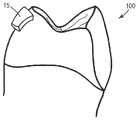
도 1은 본 발명의 일 실시 형태에 따른 브래킷 수용 영역의 결정을 예시하는 사시도이다.
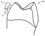
도 2는 본 발명의 일 실시 형태에 따른 평균 평면의 정의를 예시하는 사시도이다.
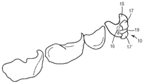
도 3은 본 발명의 일 실시 형태에 따른 치아 모형 상으로의 브래킷 헤드 외형선의 투영을 예시하는 사시도이다.
도 3a는 도 3에 사용되는 바와 같은 예비 브래킷 헤드 외형선의 평면도이다.
도 4는 본 발명의 일 실시 형태에 따른 브래킷 헤드 외형선에 오프셋을 제공하는 단계를 예시하는 사시도이다.
도 5는 본 발명의 일 실시 형태에 따른 가상 타이 윙 및 가상 브래킷 본체의 병합을 예시하는 사시도이다.
도 6은 본 발명의 일 실시 형태에 따른 가상 브래킷의 가상 표현의 사시도이다.
도 7은 본 발명의 일 실시 형태에 따른 환자의 치아 상의 물리적 브래킷의 사시도이다.
도 8은 본 발명의 일 실시 형태에 따른 환자의 치아 상의 물리적 브래킷의 추가 사시도이다.1 is a perspective view illustrating a determination of a bracket receiving area according to an embodiment of the present invention.
2 is a perspective view illustrating the definition of an average plane according to an embodiment of the present invention.
3 is a perspective view illustrating the projection of the outline of the bracket head onto the tooth model according to an embodiment of the present invention.
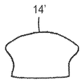
FIG. 3A is a plan view of a spare bracket head outline as used in FIG.
4 is a perspective view illustrating the step of providing an offset to the bracket head outline according to an embodiment of the present invention.
5 is a perspective view illustrating the merging of a virtual tie wing and a virtual bracket body in accordance with an embodiment of the present invention.
6 is a perspective view of a virtual representation of a virtual bracket according to an embodiment of the invention.
7 is a perspective view of a physical bracket on a patient's teeth according to an embodiment of the invention.
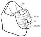
8 is an additional perspective view of a physical bracket on a patient's teeth in accordance with an embodiment of the present invention.
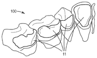
도 1은 환자의 치열의 일부의 3차원 컴퓨터 표현 또는 치아 모형(100)을 도시한다. 치아 모형(100)은 환자의 치열의 외부 표면 또는 쉘(shell)의 점들을 정의하는 많은 3차원 좌표들에 기초한다. 도시된 치아 모형(100)은 와이어 프레임 모형의 형태로 CAD 시스템의 컴퓨터 스크린 상에 디스플레이될 수 있는데, 좌표들이 작은 삼각형들의 코너들을 형성한다. 또는, 도시된 치아 모형(100)은 (비가시적) 좌표를 통한 연속되고 음영처리된 (선택적으로, 의사 컬러 렌더링(false color rendering)으로서 채색된) 가상 쉘의 형태의 렌더링으로서 디스플레이될 수 있다.FIG. 1 illustrates a three-dimensional computer representation of a portion of a patient's dentition or
환자의 치아의 치아 모형은 환자의 치아의 포지티브 또는 네거티브 물리적 모형, 예를 들어 환자의 치아로부터 취해진 석고 모형 또는 치과 인상(dental impression)을 스캐닝함으로써 획득될 수 있다. 적합한 스캐너는, 예를 들어, 독일 소재의 쓰리엠 도이칠란트 게엠베하(3M Deutschland GmbH)로부터의 상표명 라바(LAVA)™ 다자인 시스템즈(Design Systems)로 입수가능한 시스템에 제공되어 있다.A tooth model of a patient's teeth can be obtained by scanning a positive or negative physical model of the patient ' s teeth, e.g., a gypsum model or a dental impression taken from the patient's teeth. Suitable scanners are provided, for example, in systems available under the trade designation LAVA (TM) Design Systems from 3M Deutschland GmbH, Germany.
대안적으로, 치아 모형은 미국 미네소타주 세인트 폴 소재의 쓰리엠 컴퍼니(3M Company)로부터 입수가능한 쓰리엠 트루 데피니션 스캐너(3M True Definition Scanner)와 같은 구강내 스캐너에 의해 체내에서(in vivo) 환자의 치아를 스캐닝함으로써 획득될 수 있다.Alternatively, the tooth model may be obtained from a patient's in-vivo patient's teeth by an intraoral scanner, such as a 3M True Definition Scanner, available from 3M Company, St. Paul, Minn. Scanning can be obtained.
복수의 브래킷 수용 영역(11)들이 치아 모형(100) 상에 배열된다. 브래킷 수용 영역(11)은 치아 모형(100) 상에서 직접 사용자에 의한 컴퓨터 지원에 의해 결정된다. 그러나, 당업자는 브래킷 수용 영역(11)이 치아 모형(100)의 복제본 상에서 결정될 수 있거나, 또는 그와 달리, 예를 들어 업로딩, 스캐닝에 의해 또는 임의의 다른 적절한 방식으로, 제공될 수 있다는 것을 인식할 것이다. 본 예에서, 브래킷 수용 영역(11)의 외형선은 치아 모형(100) 상의 사용자에 의해 정의된 점들에 기초하여 그려진 스플라인으로부터 획득된다. 예를 들어, 사용자는 치아 모형(100) 상의 일정 점들 상에 클릭할 수 있고 CAD 시스템은 그에 기초하여 스플라인을 자동으로 생성하여 브래킷 수용 영역의 외형선을 생성할 수 있다. CAD 시스템은 바람직하게는 브래킷 수용 영역의 크기를 결정하고, 예를 들어 영역이 완성된 브래킷과 환자의 치아 사이에 우수한 접합을 제공하기에 충분히 크다는 것을 확실히 하게 하도록, 브래킷 수용 영역이 너무 작은 경우에 사용자에게 경고를 제공하는 기능을 갖는다. 추가로, CAD 시스템은, 예를 들어 치아 모형(100) 상의 원의 형태인 최소 브래킷 수용 영역을 제안하는 기능을 가질 수 있고, 사용자는 필요한 경우 제안된 브래킷 수용 영역을 연장시킬 수 있다. 전형적으로, 브래킷 수용 영역은 유의한 곡률을 갖는 치아 표면의 부분들을 덮기에 충분히 크게 설계된다. 따라서, 완성된 브래킷은 브래킷 베이스가 치아 표면과 형상이 매칭되는 치아 상의 적절한 위치로 용이하게 "스냅결합(snap)"될 수 있다.A plurality of bracket receiving areas (11) are arranged on the tooth model (100). The
그렇게 형성된 브래킷 수용 영역은, 예를 들어 서로로부터 평행하게 오프셋되어 이격된 브래킷 수용 영역의 2개의 복제본을 제공함으로써, 브래킷 베이스를 생성하는 데 사용될 수 있다. 복제본들 중 하나는 브래킷 베이스의 가상 치아 대면 표면을 생성하는 데 이용될 수 있는 반면, 다른 복제본은 브래킷 패드의 후방 표면으로서 이용될 수 있거나 또는 그를 생성하는 데 이용될 수 있다. 치아 대면 표면과 후방 표면 사이의 갭(gap)은 치아 대면 표면 및 후방 표면의 외형선들 둘레에 원주방향으로 연장된 3차원 벽에 의해 폐쇄될 수 있다. 추가로, 치아 대면 표면이 브래킷 수용 영역의 3차원 형상에 따라 전체적으로 형상화되어 있지만, 치아 대면 표면은 브래킷 수용 영역 상에 또는 치아 모형 상에 존재하지 않는 구조를 추가로 가질 수 있다. 예를 들어, 치아 대면 표면은 그리드, 버섯형 핀, 또는 다른 적절한 구조와 같은 보유 구조를 포함할 수 있다. 치아 대면 표면은 브래킷이 주문제작되는 특정 치아에 대한 브래킷을 식별하기 위하여 부호, 예를 들어 숫자를 추가로 포함할 수 있다.The bracket receiving area so formed can be used to create a bracket base, for example, by providing two replicas of the bracket receiving area spaced apart in parallel from each other. One of the replicas can be used to create a virtual tooth facing surface of the bracket base while the other replica can be used as a back surface of the bracket pad or can be used to create it. The gap between the tooth facing surface and the back surface can be closed by a three dimensional wall extending circumferentially around the contour lines of the tooth facing surface and the back surface. In addition, although the tooth-facing surface is entirely shaped according to the three-dimensional shape of the bracket receiving area, the tooth-facing surface may additionally have a structure that is not present on the bracket receiving area or on the tooth model. For example, the tooth facing surface may comprise a retention structure such as a grid, mushroom-shaped pin, or other suitable structure. The tooth facing surface may further include a number, e.g., a number, to identify the bracket for the particular tooth to which the bracket is custom made.
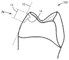
본 예에서, 브래킷 수용 영역은 그 브래킷 수용 영역의 평균 평면을 형성하는 데 이용된다. 평균 평면을 유도하기 위하여, 가상 수직 벡터가 브래킷 수용 영역을 정의하는 좌표들에 의해 형성되는 가장 작은 삼각형들의 각각에 할당될 수 있다. 삼각형 각각이 가상 하위-평면을 형성하기 때문에, 복수의 가상 수직 벡터들은 그러한 하위-평면들 상에 가상적으로 정립(erect)될 수 있다. 궁극적으로 불균일하게 배향되는 복수의 그러한 정립된 벡터들로부터, 합성 벡터가 벡터 해석에 의해 결정되고, 합성 벡터는 합성 벡터에 대한 수직 평면으로서 평균 평면을 생성하는 데 이용된다.In this example, the bracket receiving area is used to form the average plane of its bracket receiving area. To derive an average plane, a virtual vertical vector may be assigned to each of the smallest triangles formed by the coordinates defining the bracket acceptance area. Since each of the triangles forms a virtual sub-plane, a plurality of virtual vertical vectors can be virtually erected on such sub-planes. From a plurality of such set vectors that are ultimately unevenly oriented, the resultant vector is determined by a vector analysis, and the resultant vector is used to generate an average plane as a vertical plane for the resultant vector.
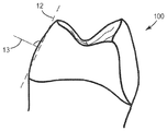
도 2는 치아 모형(100)의 치아 상에 형성되고 합성 벡터(13)에 수직인 그러한 평균 평면(12)을 도시한다.Figure 2 shows such an
도 3에서, 치아 모형(100)은 브래킷 헤드의 외형선(14)이 치아 모형(100) 상에서 결정된 상태로 도시되어 있다. 브래킷 헤드 외형선(14)은 평균 평면(12) 또는 평균 평면(12)에 평행한 가상 평면에 제공되는 예비 브래킷 헤드 외형선(14')의 투영에 의해 결정된다. 본 예에서, 예비 브래킷 헤드 외형선(14)은 복수의 상이한 예비 브래킷 헤드 외형선들을 보유하는 라이브러리로부터 검색된다. 라이브러리 내의 예비 브래킷 헤드 외형선들은 1개, 2개, 3개 또는 4개의 타이 윙을 갖는 브래킷 유형에 대해 이용가능하고 표준화될 수 있다.In Fig. 3, the
도 3a는 브래킷을 위한 단일 타이 윙의 외곽선을 형성하기 위한 그러한 표준화된 예비 브래킷 헤드 외형선을 도시한다.3A shows such a standardized spare bracket head contour line for forming the outline of a single tie wing for a bracket.
도 4는 브래킷 헤드 외형선(14)의 오프셋(15)을 도시한다. 오프셋(15)은 (도 3에 도시된) 평균 평면(12)에 기초하여 평행한 오프셋으로부터 획득된다. 타이 윙은 앞서 브래킷 베이스에 대해 설명된 바와 같은 유사한 방식으로 오프셋(15) 및 브래킷 헤드 외형선(14)에 기초하여 생성될 수 있다.Figure 4 shows the offset 15 of the bracket
도 5는 가상 브래킷 본체(17)에 대해 위치설정된 (가상) 타이 윙(16)을 도시한다. 브래킷 본체(17)는 복수의 상이한 표준화된 브래킷 본체들을 보유하는 라이브러리로부터 획득될 수 있다. 본 예에서, 브래킷 본체는 치아 모형(100)에 대해 위치설정될 수 있다. 그러한 위치는 원하는 위치 그리고/또는 초기 위치에서 환자의 치열의 가상 모형에 위치된 가상 아치와이어의 위치로부터 유도될 수 있다. 예를 들어, 아치와이어는 치열의 치아의 설측 또는 순측까지의 최소 거리에서 소위 직선 와이어 기법(straight wire technique)에 따라 설계될 수 있다. 직선 와이어 기법에서, 아치와이어는 그것이 U-형상으로 만곡되더라도 대체적으로는 평면 내에서 연장된다. 가상 브래킷 본체의 슬롯은 아치와이어에 대해 적절히 위치설정될 수 있고, 본체의 나머지는 본체가 실질적으로 치아 모형(100) 상의 브래킷 수용 영역의 중간 영역을 통하여 연장되도록 사용자에 의해 위치설정될 수 있다. 본 발명을 위해 또한 사용될 수 있는 것과 같이 가상 브래킷 본체와 가상 브래킷 패드 또는 베이스를 조합함으로써 브래킷을 제조하는 방법이 예를 들어 EP 1 474 064 B1에 더 상세히 개시되어 있다.Figure 5 shows the
타이 윙(16)은 CAD 기능을 이용하여 (도시된 바와 같이) 사용자에 의해 위치설정될 수 있다. 예를 들어, 타이 윙(16)의 치아 형상 표면들이 치아 모형(100)의 대응하는 영역 부분들로부터 바람직하게는 평행하게 오프셋되는 반면, 타이 윙(16)의 3차원 위치는 타이 윙을 원하는 위치로 이동시킴으로써 사용자에 의해 결정될 수 있다. 다시 말하면, 타이 윙(16)의 배향은 고정될 수 있는 반면, 타이 윙(16)의 3차원 위치는 가변할 수 있다. 추가로, 타이 윙(16)의 배향의 고정은 배향의 변화가 사용자에게 가능하도록 온(on) 또는 오프(off)로 전환가능할 수 있다.The
타이 윙(16)이 일단 적절히 위치설정되면, 타이 윙(16) 및 본체(17)는 컴퓨터 지원에 의해 병합될 수 있다. (도 6에 도시된) 추가 타이 윙(17')이 동일한 방식으로 획득될 수 있다.Once the
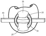
도 6은 2개의 타이 윙(17, 17'), 브래킷 베이스(18), 브래킷 본체(16) 및 아치와이어 슬롯(19)을 갖는 가상 치과교정용 브래킷(10)을 도시한다. 가상 치과교정용 브래킷(10)은 컴퓨터 처리가능 데이터의 형태로 제조 기계에 제공될 수 있다. 그러한 기계는 도 7에 도시된 바와 같은 물리적 치과교정용 브래킷을 생성하는 데 사용될 수 있다. 바람직하게는, 전체 주문제작형 치과교정용 브래킷은 선택적 레이저 용융의 이용에 의해 하나의 단일 피스로서 제조될 수 있다.Figure 6 shows a virtual dental
도 7은 환자의 치아(200)에 부착된 완성된 물리적 치과교정용 브래킷(20)을 도시한다. 치아(200)에 대한 브래킷(20)의 부착을 위하여, 접착제 또는 시멘트가 사용될 수 있다. 적합한 시멘트는 예를 들어 쓰리엠 도이칠란트 게엠베하로부터의 상표명 렐리엑스(RelyX)™ 유니셈 셀프-어드헤시브 레진 시멘트(Unicem Self-Adhesive Resin Cement)로 입수가능하다. 도시된 바와 같이, 타이 윙(26, 26')은 타이 윙 아래의 영역에서 치아(20)의 형상을 따르는 브래킷 헤드 표면(26a, 26a')을 내보인다. 따라서, 본 발명의 브래킷은 치과교정 치료를 받는 환자에게 어떠한 불편함도 최소화하는 것을 돕는다.7 shows a completed physical dental
도 8은 타이 윙(26, 26a) 위에서 묶이고 아치와이어(40)를 브래킷(20)에 부착하는 결찰사(30)를 도시한다.Fig. 8 shows
Claims (15)
- 환자의 치아의 적어도 일부의 형상을 나타내는 3차원 치아 모형을 제공하는 단계;
- 상기 치아 모형 상에 브래킷 수용 영역을 결정하는 단계;
- 상기 브래킷 수용 영역의 상기 3차원 형상에 따라 형상화되는 치아 대면 표면을 상기 브래킷 베이스에 제공하는 단계;
- 상기 치아 모형 상에 상기 브래킷 헤드의 외형선을 결정하는 단계; 및
- 상기 브래킷 헤드 외형선 내에서 상기 3차원 형상에 따라 형상화된 브래킷 헤드 표면을 상기 브래킷 헤드에 제공하는 단계를 포함하는, 방법.A method of making a custom dental orthodontic bracket, the bracket comprising a bracket base, a bracket body and an archwire slot for attaching the bracket in a patient's teeth, the bracket body comprising: The bracket head defining a bracket head extending in the dimension of the bracket height and adjacent to the free end of the bracket body, the bracket head forming a ligation portion that forms a projection with a dimension of the bracket width relative to the other bracket body portion, silver
Providing a three-dimensional tooth model representing the shape of at least a portion of the patient's teeth;
Determining a bracket receiving area on the tooth model;
- providing a tooth-facing surface to the bracket base shaped according to the three-dimensional shape of the bracket receiving area;
Determining an outline of the bracket head on the tooth model; And
- providing the bracket head to a bracket head surface shaped according to the three-dimensional shape within the bracket head contour line.
- 가상 평면에서 예비 브래킷 헤드 외형선을 결정하는 단계; 및
- 상기 치아 모형 상에 상기 예비 브래킷 헤드 외형선을 투영하고 그에 의해 상기 브래킷 헤드 외형선을 결정하는 단계를 포함하는, 방법.5. The method according to any one of claims 1 to 4,
Determining a spare bracket head contour line in a virtual plane; And
- projecting the spare bracket head contour line on the tooth model and thereby determining the bracket head contour line.
- 치료 계획의 일부로서 초기 위치 및 원하는 위치에서 상기 환자의 치아의 위치 및 배향을 결정하는 단계;
- 상기 치아의 상기 원하는 위치에서 동일 환자의 몇몇 치아에 대한 아치와이어 형상 및 위치를 결정하는 단계; 및
- 상기 브래킷의 상기 아치와이어 슬롯을 상기 아치와이어 형상 및 위치의 적절한 위치 및 배향으로 제공하는 단계를 포함하는, 방법.9. The method according to any one of claims 1 to 8,
- determining the position and orientation of the patient's teeth in an initial position and in a desired position as part of a treatment plan;
Determining an arch wire shape and position for some teeth of the same patient at said desired location of said tooth; And
- providing the arch wire slot of the bracket in an appropriate position and orientation of the arch wire shape and position.
- 컴퓨터 처리가능 데이터의 형태로 상기 브래킷의 형상을 제공하는 단계; 및
- 자동화 제조 공정에 의해 상기 브래킷을 제조하도록 상기 브래킷 데이터를 사용하는 단계를 추가로 포함하는, 방법.10. The method according to any one of claims 1 to 9,
- providing the shape of the bracket in the form of computer processable data; And
- using said bracket data to produce said bracket by an automated manufacturing process.
- 환자의 치아에서 상기 브래킷을 부착하기 위한 브래킷 베이스,
- 브래킷 본체, 및
- 아치와이어를 수용하기 위한 아치와이어 슬롯을 포함하고,
- 상기 브래킷 본체는 상기 브래킷 베이스로부터 브래킷 높이의 치수로 연장되고 상기 브래킷 본체의 자유 단부에 인접한 브래킷 헤드를 형성하고,
- 상기 브래킷 헤드는, 다른 브래킷 본체 부분에 대해, 브래킷 폭의 치수로 돌기를 형성하는 결찰 부분을 형성하고;
상기 브래킷은
- 상기 브래킷 베이스에서, 환자의 치아의 3차원 형상에 따른 3차원 형상을 갖는 브래킷 수용 영역에 따라 형상화된 치아 대면 표면; 및
- 상기 헤드 부분에서, 브래킷 헤드 외형선에 의해 형성되고 동일 환자의 치아의 3차원 형상에 따른 3차원 형상을 갖는 영역에 따라 형상화된 브래킷 헤드 표면을 추가로 포함하는, 주문제작형 치과교정용 브래킷.As a custom-made dental orthodontic bracket,
A bracket base for attaching said brackets to the patient's teeth,
- the bracket body, and
- an arch wire slot for receiving an arch wire,
The bracket body extending from the bracket base to a bracket height dimension and forming a bracket head adjacent the free end of the bracket body,
Said bracket head forming a ligation portion for forming a projection in the dimension of the bracket width relative to the other bracket body portion;
The bracket
A tooth-facing surface shaped in accordance with a bracket receiving area having a three-dimensional shape according to the three-dimensional shape of the patient's teeth, in said bracket base; And
And a bracket head surface formed by the bracket head contour line and shaped according to a region having a three-dimensional shape according to the three-dimensional shape of the teeth of the same patient, .
상기 브래킷들은 동일 환자의 치열의 상이한 특정 치아와 각각 매칭하도록 할당 및 형상화되고, 상기 키트는 상기 환자의 치아에 부착된 상기 브래킷들의 상기 슬롯들을 통하여 이어지도록 구성된 적어도 하나의 아치와이어를 추가로 포함하는, 키트.A kit of custom made orthodontic brackets according to claim 13 or 14,
Wherein the brackets are allotted and shaped to match respective different specific teeth of the same patient's dentition, the kit further comprising at least one arch wire configured to extend through the slots of the brackets attached to the patient's teeth , Kit.
Applications Claiming Priority (3)
| Application Number | Priority Date | Filing Date | Title |
|---|---|---|---|
| EP13180393.4A EP2837356A1 (en) | 2013-08-14 | 2013-08-14 | An orthodontic bracket and a method of making an orthodontic bracket |
| EP13180393.4 | 2013-08-14 | ||
| PCT/US2014/050940 WO2015023784A1 (en) | 2013-08-14 | 2014-08-13 | An orthodontic bracket and a method of making an orthodontic bracket |
Publications (1)
| Publication Number | Publication Date |
|---|---|
| KR20160042965A true KR20160042965A (en) | 2016-04-20 |
Family
ID=48985625
Family Applications (1)
| Application Number | Title | Priority Date | Filing Date |
|---|---|---|---|
| KR1020167006159A KR20160042965A (en) | 2013-08-14 | 2014-08-13 | An orthodontic bracket and a method of making an orthodontic bracket |
Country Status (8)
| Country | Link |
|---|---|
| US (1) | US9949804B2 (en) |
| EP (2) | EP2837356A1 (en) |
| JP (1) | JP2016527993A (en) |
| KR (1) | KR20160042965A (en) |
| CN (1) | CN105473101B (en) |
| BR (1) | BR112016002938A2 (en) |
| MX (1) | MX2016001833A (en) |
| WO (1) | WO2015023784A1 (en) |
Cited By (1)
| Publication number | Priority date | Publication date | Assignee | Title |
|---|---|---|---|---|
| KR102181712B1 (en) * | 2019-08-14 | 2020-11-23 | 주식회사 디오 | wire fixing bracket for orthodontics |
Families Citing this family (18)
| Publication number | Priority date | Publication date | Assignee | Title |
|---|---|---|---|---|
| EP2907476A1 (en) * | 2014-02-12 | 2015-08-19 | 3M Innovative Properties Company | A method of making a customized orthodontic bracket |
| CN106031661A (en) * | 2015-03-17 | 2016-10-19 | 首都医科大学附属北京口腔医院 | Orthodontic anchorage body |
| CN105852995B (en) * | 2016-04-27 | 2018-08-07 | 叶年嵩 | A kind of customized lingual brackets appliance and preparation method thereof |
| JP2019521811A (en) * | 2016-07-28 | 2019-08-08 | ケアストリーム・デンタル・テクノロジー・トプコ・リミテッド | Method and system for removal of orthodontic mesh orthodontic appliance |
| US20200015936A1 (en) | 2016-11-30 | 2020-01-16 | Carestream Dental Technology Topco Limited | Method and system for braces removal from dentition mesh |
| EP3595572B1 (en) * | 2017-03-15 | 2022-06-01 | 3M Innovative Properties Company | Removable orthodontic appliance system |
| US11564778B2 (en) * | 2018-03-07 | 2023-01-31 | TH!NK Innovations, LLC | Orthodontic elastic attachments for use with dental aligners |
| US11701203B2 (en) * | 2018-06-29 | 2023-07-18 | Align Technology, Inc. | Dental appliance hook placement and visualization |
| US10278794B1 (en) | 2018-09-28 | 2019-05-07 | 3D Med Ag | Systems and methods for making orthodontic brackets |
| US11273008B2 (en) | 2019-12-04 | 2022-03-15 | Oxilio Ltd | Systems and methods for generating 3D-representation of tooth-specific appliance |
| US10631956B1 (en) | 2019-12-04 | 2020-04-28 | Oxilio Ltd | Methods and systems for making an orthodontic aligner having fixing blocks |
| US10726949B1 (en) | 2019-12-05 | 2020-07-28 | Oxilio Ltd | Systems and methods for generating 3D-representation of tooth-specific platform for dental appliance |
| EP4267034A1 (en) * | 2020-12-23 | 2023-11-01 | Hirsch Dynamics Holding AG | Automatic creation of a virtual model of at least a part of an orthodontic appliance |
| WO2022135717A1 (en) * | 2020-12-23 | 2022-06-30 | Hirsch Dynamics Holding Ag | Automatic creation of a virtual model of at least a bonding part of an orthodontic bracket |
| CN114052955A (en) * | 2021-12-01 | 2022-02-18 | 浙江工业大学 | Personalized lingual bracket based on compression molding and manufacturing method thereof |
| KR102537013B1 (en) * | 2023-02-17 | 2023-05-30 | 주식회사 올소비트 | A method of manufacturing the off-the-shelf bracket attachment guide based on the clinically measured dental arch wire, and a guide manufactured thereby |
| KR102537014B1 (en) * | 2023-02-17 | 2023-05-30 | 주식회사 올소비트 | Method of manufacturing a guide integral bracket based on the clinically measured dental arch wire and the guide integral bracket manufactured thereby |
| KR102537012B1 (en) * | 2023-02-17 | 2023-05-30 | 주식회사 올소비트 | To determine the numerical measurement of the clinical dental arch wire form for orthodontic orthodontics |
Family Cites Families (8)
| Publication number | Priority date | Publication date | Assignee | Title |
|---|---|---|---|---|
| US5607301A (en) * | 1994-11-01 | 1997-03-04 | Lancer Orthodontics | Orthodontic bracket and method of mounting |
| JP2004504077A (en) * | 2000-04-19 | 2004-02-12 | オラメトリックス インコーポレイテッド | Interactive orthodontic care system based on intraoral scanning of teeth |
| US6776614B2 (en) | 2002-02-13 | 2004-08-17 | Lingualcare, Inc. | Modular system for customized orthodontic appliances |
| CN101284302B (en) * | 2008-02-27 | 2011-06-15 | 华南理工大学 | Selective laser sintering indirect manufacturing method of individuation tongue side orthodontic bracket |
| CN100586611C (en) * | 2008-02-27 | 2010-02-03 | 华南理工大学 | Selective laser melting direct manufacturing method of customized tongue side orthodontic bracket |
| CN101647729B (en) | 2009-09-11 | 2012-11-14 | 广州瑞通生物科技有限公司 | Manufacture method of individual orthodontic appliance for tongue |
| CN103037755A (en) | 2010-07-28 | 2013-04-10 | 雅培糖尿病护理股份有限公司 | Analyte sensors having temperature independent membranes |
| CN103027755A (en) * | 2012-12-13 | 2013-04-10 | 广州瑞通生物科技有限公司 | Individual tongue side self-locking appliance |
-
2013
- 2013-08-14 EP EP13180393.4A patent/EP2837356A1/en not_active Ceased
-
2014
- 2014-08-13 JP JP2016534820A patent/JP2016527993A/en active Pending
- 2014-08-13 WO PCT/US2014/050940 patent/WO2015023784A1/en active Application Filing
- 2014-08-13 CN CN201480045165.9A patent/CN105473101B/en active Active
- 2014-08-13 KR KR1020167006159A patent/KR20160042965A/en not_active Application Discontinuation
- 2014-08-13 MX MX2016001833A patent/MX2016001833A/en unknown
- 2014-08-13 BR BR112016002938A patent/BR112016002938A2/en not_active Application Discontinuation
- 2014-08-13 US US14/911,705 patent/US9949804B2/en active Active
- 2014-08-13 EP EP14755755.7A patent/EP3033037B1/en active Active
Cited By (1)
| Publication number | Priority date | Publication date | Assignee | Title |
|---|---|---|---|---|
| KR102181712B1 (en) * | 2019-08-14 | 2020-11-23 | 주식회사 디오 | wire fixing bracket for orthodontics |
Also Published As
| Publication number | Publication date |
|---|---|
| US9949804B2 (en) | 2018-04-24 |
| WO2015023784A1 (en) | 2015-02-19 |
| US20160199154A1 (en) | 2016-07-14 |
| EP2837356A1 (en) | 2015-02-18 |
| CN105473101B (en) | 2019-07-16 |
| MX2016001833A (en) | 2016-04-15 |
| JP2016527993A (en) | 2016-09-15 |
| EP3033037A1 (en) | 2016-06-22 |
| BR112016002938A2 (en) | 2017-08-01 |
| EP3033037B1 (en) | 2020-05-06 |
| CN105473101A (en) | 2016-04-06 |
Similar Documents
| Publication | Publication Date | Title |
|---|---|---|
| KR20160042965A (en) | An orthodontic bracket and a method of making an orthodontic bracket | |
| US10292789B2 (en) | Tooth positioning appliance with curved interconnecting elements | |
| JP6385404B2 (en) | Rapid prototype transfer tray for orthodontic appliances | |
| US10314673B2 (en) | System for producing a one-piece orthodontic jig and brackets | |
| US10028804B2 (en) | System for producing a one-piece orthodontic jig and attachments | |
| CN105979907B (en) | The method for making customization orthodontic bracket | |
| US8371847B2 (en) | Method for designing orthodontic apparatus | |
| US20200375698A1 (en) | Removable dental appliance including positioning member | |
| US20220061962A1 (en) | Removable dental appliance including spring member | |
| KR20210072120A (en) | Removable dental instruments with gingival ridges | |
| US20190223984A1 (en) | Dental apparatus for bonding orthodontic appliance to dental arch and process thereof | |
| CN108697488B (en) | Orthodontic bracket and method of manufacturing orthodontic bracket | |
| US20210244508A1 (en) | Method of an orthodontic treatment, use of a pearl as a holding element for an orthodontic appliance and a pearl for an orthodontic treatment | |
| AU2016203563B2 (en) | Tooth positioning appliance with curved interconnecting elements | |
| CA2932100C (en) | Tooth positioning appliance with curved interconnecting elements | |
| Mehta et al. | ARCH FORM: IS THE SHAPE RIGHT. |
Legal Events
| Date | Code | Title | Description |
|---|---|---|---|
| WITN | Withdrawal due to no request for examination |