KR20160030509A - Video-based auto-capture for dental surface imaging apparatus - Google Patents
Video-based auto-capture for dental surface imaging apparatus Download PDFInfo
- Publication number
- KR20160030509A KR20160030509A KR1020167000693A KR20167000693A KR20160030509A KR 20160030509 A KR20160030509 A KR 20160030509A KR 1020167000693 A KR1020167000693 A KR 1020167000693A KR 20167000693 A KR20167000693 A KR 20167000693A KR 20160030509 A KR20160030509 A KR 20160030509A
- Authority
- KR
- South Korea
- Prior art keywords
- tooth
- obtaining
- camera
- equivalent line
- video image
- Prior art date
Links
Images


Classifications
-
- A—HUMAN NECESSITIES
- A61—MEDICAL OR VETERINARY SCIENCE; HYGIENE
- A61C—DENTISTRY; APPARATUS OR METHODS FOR ORAL OR DENTAL HYGIENE
- A61C9/00—Impression cups, i.e. impression trays; Impression methods
- A61C9/004—Means or methods for taking digitized impressions
- A61C9/0046—Data acquisition means or methods
- A61C9/0053—Optical means or methods, e.g. scanning the teeth by a laser or light beam
- A61C9/006—Optical means or methods, e.g. scanning the teeth by a laser or light beam projecting one or more stripes or patterns on the teeth
-
- A—HUMAN NECESSITIES
- A61—MEDICAL OR VETERINARY SCIENCE; HYGIENE
- A61B—DIAGNOSIS; SURGERY; IDENTIFICATION
- A61B5/00—Measuring for diagnostic purposes; Identification of persons
- A61B5/0059—Measuring for diagnostic purposes; Identification of persons using light, e.g. diagnosis by transillumination, diascopy, fluorescence
- A61B5/0082—Measuring for diagnostic purposes; Identification of persons using light, e.g. diagnosis by transillumination, diascopy, fluorescence adapted for particular medical purposes
- A61B5/0088—Measuring for diagnostic purposes; Identification of persons using light, e.g. diagnosis by transillumination, diascopy, fluorescence adapted for particular medical purposes for oral or dental tissue
-
- A—HUMAN NECESSITIES
- A61—MEDICAL OR VETERINARY SCIENCE; HYGIENE
- A61B—DIAGNOSIS; SURGERY; IDENTIFICATION
- A61B5/00—Measuring for diagnostic purposes; Identification of persons
- A61B5/45—For evaluating or diagnosing the musculoskeletal system or teeth
- A61B5/4538—Evaluating a particular part of the muscoloskeletal system or a particular medical condition
- A61B5/4542—Evaluating the mouth, e.g. the jaw
- A61B5/4547—Evaluating teeth
-
- A—HUMAN NECESSITIES
- A61—MEDICAL OR VETERINARY SCIENCE; HYGIENE
- A61C—DENTISTRY; APPARATUS OR METHODS FOR ORAL OR DENTAL HYGIENE
- A61C19/00—Dental auxiliary appliances
- A61C19/04—Measuring instruments specially adapted for dentistry
-
- G—PHYSICS
- G01—MEASURING; TESTING
- G01B—MEASURING LENGTH, THICKNESS OR SIMILAR LINEAR DIMENSIONS; MEASURING ANGLES; MEASURING AREAS; MEASURING IRREGULARITIES OF SURFACES OR CONTOURS
- G01B11/00—Measuring arrangements characterised by the use of optical techniques
- G01B11/24—Measuring arrangements characterised by the use of optical techniques for measuring contours or curvatures
- G01B11/25—Measuring arrangements characterised by the use of optical techniques for measuring contours or curvatures by projecting a pattern, e.g. one or more lines, moiré fringes on the object
- G01B11/2518—Projection by scanning of the object
-
- A—HUMAN NECESSITIES
- A61—MEDICAL OR VETERINARY SCIENCE; HYGIENE
- A61B—DIAGNOSIS; SURGERY; IDENTIFICATION
- A61B2576/00—Medical imaging apparatus involving image processing or analysis
-
- A—HUMAN NECESSITIES
- A61—MEDICAL OR VETERINARY SCIENCE; HYGIENE
- A61B—DIAGNOSIS; SURGERY; IDENTIFICATION
- A61B5/00—Measuring for diagnostic purposes; Identification of persons
- A61B5/0033—Features or image-related aspects of imaging apparatus classified in A61B5/00, e.g. for MRI, optical tomography or impedance tomography apparatus; arrangements of imaging apparatus in a room
- A61B5/004—Features or image-related aspects of imaging apparatus classified in A61B5/00, e.g. for MRI, optical tomography or impedance tomography apparatus; arrangements of imaging apparatus in a room adapted for image acquisition of a particular organ or body part
-
- G—PHYSICS
- G16—INFORMATION AND COMMUNICATION TECHNOLOGY [ICT] SPECIALLY ADAPTED FOR SPECIFIC APPLICATION FIELDS
- G16H—HEALTHCARE INFORMATICS, i.e. INFORMATION AND COMMUNICATION TECHNOLOGY [ICT] SPECIALLY ADAPTED FOR THE HANDLING OR PROCESSING OF MEDICAL OR HEALTHCARE DATA
- G16H30/00—ICT specially adapted for the handling or processing of medical images
- G16H30/40—ICT specially adapted for the handling or processing of medical images for processing medical images, e.g. editing
Abstract
컴퓨터에 의해 적어도 부분적으로 실행될 수 있는 치아의 등가선 이미지를 획득하기 위한 예시적 방법에서, 치아를 포함하는 제1 비디오 이미지 프레임을 획득하고 제1 비디오 이미지 프레임을 프로세싱하여 상기 제1 비디오 이미지 프레임 내 치아의 하나 이상의 가장자리를 검출하고, 치아를 포함하는 제2 비디오 이미지 프레임을 획득하고 제2 비디오 이미지 프레임을 프로세싱하여 상기 제2 비디오 이미지 프레임 내 치아의 하나 이상의 가장자리를 검출함으로써 구강내 카메라의 움직임이 검출될 수 있다. 상기 방법은 프로세싱된 제1 비디오 이미지 프레임과 제2 비디오 이미지 프레임 간 대응하는 가장자리 위치들을 비교할 수 있고, 카메라로부터 프린지 패턴 조명을 치아 상으로 투사하고, 검출된 카메라 움직임에 따라 프린지 패턴의 하나 이상의 정지 이미지를 캡처 및 저장할 수 있다. In an exemplary method for obtaining an equivalent line image of a tooth that may be executed at least partially by a computer, a first video image frame comprising a tooth is acquired and a first video image frame is processed to produce a first video image frame Motion of the intraoral camera is detected by detecting one or more edges of the teeth, acquiring a second video image frame comprising teeth, and processing a second video image frame to detect one or more edges of the teeth in the second video image frame Can be detected. The method can compare edge positions corresponding between the processed first video image frame and the second video image frame, project fringe pattern illumination from the camera onto the teeth, detect one or more stops of the fringe pattern Images can be captured and saved.

Description
본 발명은 구조광을 이용한 진단 이미징의 분야와 관련되고 더 구체적으로 치아 및 그 밖의 다른 구조물의 표면의 3차원 이미징을 위한 프린지 패턴(fringe pattern) 이미지의 자동 캡처를 위한 방법과 관련된다.The present invention relates to the field of diagnostic imaging using structured light, and more particularly to a method for automatic capture of fringe pattern images for three-dimensional imaging of the surfaces of teeth and other structures.
프린지 투사 이미징은 패턴광 또는 구조광을 이용하여 다양한 유형의 구조물에 대한 표면 등가선(contour) 정보를 획득할 수 있다. 프린지 투사 이미징에서, 간섭 프린지 또는 격자가 특정 방향으로부터 물체의 표면을 향해 투사된다. 그 후 등가선의 겉모습을 기초로 하여 표면 정보를 분석하기 위해 삼각측량을 이용해 표면에서 투사된 패턴이 또 다른 방향에서 등가선 이미지로서 관찰된다. 새 위치에서 추가 측정을 제공하는 이미지를 획득하기 위해 투사된 패턴이 점차 공간적으로 편이되는 위상 편이가 표면의 등가선 맵핑을 완료하고 등가선 이미지에서 전체 해상도를 증가시키기 위해 프린지 투사 이미징의 일부로서 적용되는 것이 일반적이다. Fringe projection imaging can acquire surface equivalent contour information for various types of structures using patterned light or structured light. In fringe projection imaging, an interference fringe or grating is projected from a particular direction toward the surface of the object. The pattern projected from the surface using triangulation is then observed as an isosceles image in another direction to analyze the surface information based on the appearance of the equivalent line. Phase shifting, in which the projected pattern is gradually spatially shifted to obtain an image providing additional measurements at the new location, is applied as part of the fringe projection imaging to complete the equivalent line mapping of the surface and to increase the overall resolution in the equivalent line image .
속이 찬 불투명한 물체의 표면 등가선 이미징에 대해 효과적으로 프린지 투사 이미징 및 그 밖의 다른 패턴광 이미징 기법이 사용되어 왔고, 인체의 일부 부분에 대한 표면 등가선을 특징화하기 위해 그리고 피부 구조물에 대한 상세한 데이터를 획득하기 위해 사용되어 왔다. 그러나 복수의 기술적 장애물이 치아의 패턴광 이미징의 효과적인 사용을 복잡하게 만든다. 치아 표면 이미징에서의 한 가지 특정 과제는 치아 반투명성(tooth translucency)과 관련된다. 일반적으로 프린지 투사 이미징에서 반투명 또는 아반투명 물질이 특히 문제가 된다고 알려져있다. 반투명 구조물에서의 표면아래 산란(subsurface scattering)이 전체 신호-대-잡음(S/N) 비를 감소시킬 수 있고, 광도를 편이시켜, 부정확한 높이 데이터를 야기할 수 있다. 또 다른 문제는 다양한 치아 표면에 대한 높은 레벨의 반사와 관련된다. 고도 반사성 물질, 특히, 중공 반사성 구조물이 이러한 유형의 이미징의 다이내믹 레인지(dynamic range)를 유효하게 감소시킬 수 있다. Fringe projection imaging and other patterned light imaging techniques have been effectively used for surface equilibrium imaging of hollow opaque objects and have been used to characterize the surface equilibrium for some parts of the body and to provide detailed data on skin structures ≪ / RTI > However, multiple technical barriers complicate the effective use of patterned light imaging of the teeth. One particular challenge in tooth surface imaging is related to tooth translucency. It is generally known that semitransparent or translucent materials are particularly problematic in fringe projection imaging. Subsurface scattering in a translucent structure can reduce the overall signal-to-noise (S / N) ratio and can shift the light intensity, resulting in inaccurate height data. Another problem is associated with high levels of reflections on various tooth surfaces. Highly reflective materials, in particular, hollow reflective structures, can effectively reduce the dynamic range of this type of imaging.
광학 관점에서, 치아 구조물 자체가 프린지 투사 이미징에 대한 많은 추가 과제를 제시한다. 앞서 언급된 바와 같이, 치아의 표면 아래를 투과하는 광이 반투명 치아 물질 내에서 상당한 산란을 겪는 경향이 있다. 덧붙이자면, 치아 표면 아래의 불투명 특징부로부터의 반사가 또한 발생할 수 있고, 이는 감지된 신호를 열화시키는 잡음을 추가하며, 따라서 치아 표면 분석의 작업을 더 복잡하게 만든다. From an optical point of view, the tooth structure itself presents many additional challenges for fringe projection imaging. As mentioned previously, light transmitted under the surface of the teeth tends to undergo significant scattering in the translucent tooth material. Additionally, reflections from the opaque features below the tooth surface can also occur, adding noise that degrades the sensed signal, thus further complicating the task of tooth surface analysis.
프린지 투사가 치아의 등가선 이미징에 효과가 있도록 만들려 시도한 한 가지 교정 수단이 치아 표면 자체의 반사 특성을 변경하는 코팅을 도포하는 것이다. 여기서, 치아의 상대적 투명도에 의해 야기되는 문제를 보상하기 위해, 복수의 종래의 치아 등가선 이미징 시스템이 표면 등가선 이미징 전에 페인트 또는 반사성 파우더를 치아 표면에 도포한다. 프린지 투사 이미징을 위해, 이 추가되는 단계는 치아의 불투명성을 향상시키고 앞서 언급된 산란되는 광 효과를 제거하거나 감소시킨다. 그러나 이러한 유형의 방식에 단점이 존재한다. 코팅 파우더 또는 액체를 도포하는 단계는 치아 등가선 이미징 프로세스에 비용과 시간을 추가한다. 종종 전체 치아 표면에 걸쳐 코팅 층의 두께가 불균일하기 때문에, 측정 오차가 쉽게 초래된다. 더 중요한 것은, 도포되는 코팅은 등가선 이미징을 촉진하더라도, 치아의 다른 문제를 덮는 경향을 가질 수 있으며, 따라서 획득될 수 있는 정보의 전체 양을 감소시킬 수 있다. 코팅 또는 그 밖의 다른 유형의 치아의 표면 처리가 사용되는 경우라도, 치아 표면의 뚜렷한 등가선 때문에 결과가 실망스러울 수 있다.One corrective measure that attempts to make fringe projections effective in imaging the equilibrium of teeth is to apply a coating that changes the reflection properties of the tooth surface itself. Here, in order to compensate for the problems caused by the relative transparency of the teeth, a plurality of conventional tooth equivalent line imaging systems apply paint or reflective powder to the tooth surface before surface isocontrast imaging. For fringe projection imaging, this added step improves the opacity of the teeth and eliminates or reduces the aforementioned scattered light effects. However, there are drawbacks to this type of approach. The step of applying coating powder or liquid adds cost and time to the tooth equivalent line imaging process. Since the thickness of the coating layer is often non-uniform over the entire tooth surface, measurement errors are easily caused. More importantly, even if the applied coating promotes isosurface imaging, it may have a tendency to cover other problems of the tooth, thus reducing the overall amount of information that can be acquired. Even when a surface treatment of a coating or other type of tooth is used, the result may be disappointing due to the pronounced equilibrium line of the tooth surface.
치아 구조 이미징의 문제에 구조광 표면-프로파일링 기법을 적응시키기 위한 복수의 시도가 존재했다. 예를 들어, Massen외에게 허여된 미국 특허 제5,372,502호, 발명의 명칭 "Optical Probe and Method for the Three-Dimensional Surveying of Teeth"가 치아 표면 상으로의 투사를 위한 줄무늬 패턴을 형성하기 위한 LCD 매트릭스의 사용을 기술한다. 유사한 방식이 O'Keefe외의 미국 특허 출원 공개 번호 2007/0086762호 발명의 명칭 "Front End for 3-D Imaging Camera"에 기술되어 있다. Trissel에게 허여된 미국 특허 제7,312,924호 발명의 명칭 "Polarizing Multiplexer and Methods for Intra-Oral Scanning"가 삼각측량 및 편광된 광을 이용해 치아 표면을 프로파일링하기 위한 방법을 기술하지만, 이는 동작을 위한 형광 코팅의 도포를 필요로 한다. 마찬가지로, Pfeiffer외에게 허여된 미국 특허 제6,885,464호 발명의 명칭 "3-D Camera for Recording Surface Structures, in Particular for Dental Purposes"이 삼각측량을 이용하는 치아 이미징 장치를 개시하고 있지만, 이 또한 이미징을 위해 불투명한 파우더를 치아 표면에 도포하는 것을 필요로 한다. Pfeiffer외에게 허여된 미국 특허 제6,885,464호는 이미징을 위한 광 빔들의 그룹을 제공하는 구강내 카메라를 기술한다. Lim에 의한 특허 출원 WO 2011/145799가 스캐닝된 레이저 광을 이용하는 3-D 스캐너를 기술한다. There have been several attempts to adapt the structural light surface-profiling technique to the problem of tooth structure imaging. For example, U.S. Patent No. 5,372,502 issued to Massen et al., Entitled " Optical Probe and Method for the Three-Dimensional Surveying of Teeth ", of the LCD matrix for forming a stripe pattern for projection onto a tooth surface Describe the use. A similar approach is described in O'Keefe et al., U.S. Patent Application Publication No. 2007/0086762 entitled " Front End for 3-D Imaging Camera ". US Patent No. 7,312,924 to Trissel entitled " Polarizing Multiplexer and Methods for Intra-Oral Scanning " describes a method for profiling a tooth surface using triangulation and polarized light, . Likewise, although US Patent No. 6,885,464 entitled " 3-D Camera for Recording Surface Structures, Particular for Dental Purposes ", issued to Pfeiffer et al., Discloses a tooth imaging device using triangulation, It is necessary to apply one powder to the tooth surface. No. 6,885,464 to Pfeiffer et al. Describes an intraoral camera that provides a group of light beams for imaging. The patent application WO 2011/145799 by Lim describes a 3-D scanner using scanned laser light.
치아의 등가선 이미징에 적합한 이미징 장치의 설계 및 형태를 방해하는 어려움들 중에, 패턴광을 이용할 때 정확하고 정밀한 공간적 등록이 필요한 것이 있다. 이는 카메라를 환자의 구강 속 바람직한 위치에 위치시키고, 패턴광 이미지 또는 이미지들을 캡처하기 위해 필요한 시간 동안 카메라를 상기 바람직한 위치에서 정지 상태로 유지하는 것과 관련된 물류적 문제를 해결할 것을 요구한다. 일부 경우, 치아 및 카메라가 서로에 대해 동일한 고정 위치에 있는 둘 이상의 정지 이미지가 캡처되어야 한다.Among the difficulties hindering the design and form of an imaging device suitable for the equivalent line imaging of teeth, accurate and precise spatial registration is required when using patterned light. This entails placing the camera in a desired position in the patient's mouth and solving the logistical problems associated with keeping the camera stationary at the desired position for the time required to capture the patterned light image or images. In some cases, more than one still image should be captured where the teeth and camera are in the same fixed position relative to each other.
따라서 구강내 카메라를 이용한 표면 등가선 특징화를 위해 정지 이미지 캡처를 제공하기 위한 개선된 방법이 요구된다.Thus, there is a need for an improved method for providing still image capture for characterizing surface equivalent lines using an intraoral camera.
본 발명의 목적은 표면 등가선 특징화를 위한 치아 이미징의 분야를 진보시키는 것이다. 카메라 및 이미징되는 치아의 상대적 움직임을 검출하기 위해 비디오 이미지 프레임으로부터의 정보를 이용하고 이 검출을 기초로 등가선 이미지 캡처를 트리거할 수 있는 것이 본 발명의 특징이다. It is an object of the present invention to advance the field of tooth imaging for characterizing surface equivalent lines. It is a feature of the present invention that information from a video image frame can be used to detect the relative movement of the camera and the teeth being imaged and trigger an equivalent line image capture based on this detection.
본 발명의 장치 및 방법에 의해 제안되는 이점들 중, 추가된 카메라 구성요소 및 치아 표면의 개선된 이미징 없이 등가선 이미징을 위한 자동화된 이미지 캡처가 있다.Among the advantages offered by the apparatus and method of the present invention are automated image capture for equivalent line imaging without improved imaging of the added camera components and tooth surfaces.
이들 목적은 도시된 예시에 의해서만 제공되며, 이러한 목적은 본 발명의 하나 이상의 실시예의 예시일 수 있다. 개시된 방법에 의해 달성되는 그 밖의 다른 바람직한 목적 및 이점이 발생하거나 해당 분야의 통상의 기술자에게 자명할 수 있다. 본 발명은 첨부된 특허청구범위에 의해 규정된다. These objects are provided solely by the illustrated examples, which may be an example of one or more embodiments of the invention. Other desirable objects and advantages attained by the disclosed method may occur or may be apparent to one of ordinary skill in the art. The invention is defined by the appended claims.
본 발명의 하나의 양태에 따라, 치아의 등가선 이미지를 획득하기 위한 방법이 제공되며, 상기 방법은 컴퓨터에 의해 적어도 부분적으로 실행되며, According to one aspect of the present invention, there is provided a method for obtaining an equivalent line image of a tooth, the method being performed at least in part by a computer,
(i) 치아를 포함하는 제1 비디오 이미지 프레임을 획득하고 상기 제1 비디오 이미지 프레임을 프로세싱하여 상기 제1 비디오 이미지 프레임 내 치아의 하나 이상의 가장자리를 검출하는 단계, (i) obtaining a first video image frame comprising teeth and processing the first video image frame to detect one or more edges of the teeth in the first video image frame,
(ii) 치아를 포함하는 제2 비디오 이미지 프레임을 획득하고 상기 제2 비디오 이미지 프레임을 프로세싱하여 상기 제2 비디오 이미지 프레임 내 치아의 하나 이상의 가장자리를 검출하는 단계, (ii) obtaining a second video image frame comprising teeth and processing the second video image frame to detect one or more edges of the teeth in the second video image frame,
(iii) 프로세싱된 제1 비디오 이미지 프레임과 제2 비디오 이미지 프레임 간 대응하는 가장자리 위치들을 비교하는 단계(iii) comparing corresponding edge positions between the processed first video image frame and the second video image frame
에 의해 구강내 카메라의 움직임을 검출하는 단계, 및Detecting the movement of the intraoral camera by means of
카메라로부터 치아 상으로 프린지 패턴 조명을 투사하고 검출된 카메라 움직임에 따라 프린지 패턴의 하나 이상의 정지 이미지를 캡처 및 저장하는 단계Projecting the fringe pattern illumination from the camera to the teeth and capturing and storing one or more still images of the fringe pattern according to the detected camera motion
를 포함한다. .
본 발명의 상기의 그리고 그 밖의 다른 목적, 특징부, 및 이점이, 첨부된 도면에 도시된 바와 같이, 다음의 본 발명의 실시예의 더 구체적인 기재로부터 자명해질 것이다.
도면의 요소들이 서로에 대해 반드시 실측 비율인 것은 아니다. 동작의 기본적인 구조적 관계 또는 원리를 강조하기 위해 약간의 과장이 필요할 수 있다. 기재된 실시예의 구현을 위해 필요할 일부 종래의 구성요소, 가령, 시스템 광소자에 전력을 제공, 패키징, 및 장착 및 보호하기 위해 사용되는 지지 구성요소는, 기재를 간결화하기 위해 도면에 도시되지 않는다.
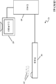
도 1a는 치아의 등가선 이미징을 위한 구강내 이미징 장치를 도시한다.
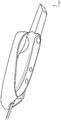
도 1b는 비디오 및 등가선 이미징 능력을 갖는 구강내 카메라를 보여주는 투시도이다.
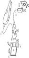
도 1c는 구강내 카메라 및 구강내 이미징 장치의 관련 구성요소와의 상호 연결을 보여주는 투시도이다.
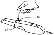
도 1d 및 1e는 등가선 이미징을 위한 수동 모드 또는 자동 모드의 운영자 선택을 도시한다.
도 2a는 치아의 등가선 이미징을 위한 프린지 패턴을 획득하기 위해 카메라를 이용하는 것을 도시한다.
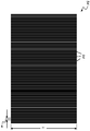
도 2b는 투사된 패턴을 보여주는 평면도이다.
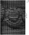
도 2c는 치아의 모델 상에 투사된 패턴을 도시한다.
도 2d는 프린지 패턴 결과를 이용해 계산되는 예시적 치아 표면을 도시한다.
도 3은 비디오 및 등가선 이미징을 위한 이미징 장치의 구성요소를 나타내는 개략적 블록도이다.
도 4는 구강내 카메라 동작의 수동 모드 및 자동 모드를 위한 단계들을 보여주는 로직 흐름도이다.
도 5는 본 발명의 실시예에 따라 자동 모션 검출 및 프린지 패턴 이미지 캡처를 보여주는 로직 흐름도이다.
도 6은 구조광 이미지 캡처를 지지하기 위해 비디오 이미지 콘텐츠를 프로세싱하는 데 사용되는 기능적 구성요소를 보여주는 흐름도이다.
도 7은 카메라 움직임을 결정하기 위한 기능적 구성요소들의 관계를 도시한다.
도 8a는 예시적 필터링된 치아 이미지를 도시한다.
도 8b는 필터링된 치아 이미지로부터 생성되는 예시적 가장자리 맵을 도시한다.
도 9는 움직임을 결정하기 위해 가장자리 맵들의 비교에 대한 타이밍 관계를 도시한다. These and other objects, features and advantages of the present invention will become apparent from the following more detailed description of embodiments of the invention, as illustrated in the accompanying drawings.
The elements of the drawings are not necessarily to scale with respect to each other. Some exaggeration may be needed to emphasize the basic structural relationships or principles of motion. The support components used to provide, package, and mount and protect power to system optical components, such as those required for the implementation of the described embodiments, are not shown in the drawings to simplify the substrate.
Figure 1A shows an intraoral imaging device for equivalent line imaging of teeth.
1B is a perspective view showing an intraoral camera with video and equivalent line imaging capability.
1C is a perspective view showing the interconnection of the intraoral camera and associated components of the intraoral imaging device.
Figures 1d and 1e illustrate the operator selection of a passive mode or an automatic mode for equivalent line imaging.
2A illustrates the use of a camera to obtain a fringe pattern for equivalent line imaging of a tooth.
2B is a plan view showing the projected pattern.
Figure 2c shows the pattern projected on the model of the tooth.
Figure 2D illustrates an exemplary tooth surface calculated using fringe pattern results.
Figure 3 is a schematic block diagram illustrating the components of an imaging device for video and equivalent line imaging.
4 is a logic flow diagram showing steps for passive mode and automatic mode of intraoral camera motion.
5 is a logic flow diagram illustrating automatic motion detection and fringe pattern image capture in accordance with an embodiment of the present invention.
Figure 6 is a flow chart showing the functional components used to process video image content to support structured light image capture.
Figure 7 shows the relationship of functional components for determining camera motion.
8A shows an exemplary filtered tooth image.
Figure 8B shows an exemplary edge map generated from the filtered tooth image.
Figure 9 shows the timing relationship for the comparison of edge maps to determine motion.
본 출원은 그 전체 내용이 본 명세서에 포함되는 Yingqian Wu외의 이름으로 2013년 07월 12일에 가출원된 미국 가특허출원 번호 제61/845,440호 발명의 명칭 "AN APPARATUS OF VIDEO-BASED AUTO-CAPTURE FOR INTRA-ORAL CAMERA"의 이익을 주장한다.This application is related to U.S. Provisional Patent Application No. 61 / 845,440 entitled " AN APPARATUS OF VIDEO-BASED AUTO-CAPTURE FOR " filed on July 12, 2013, the entire contents of which are hereby incorporated by reference, INTRA-ORAL CAMERA ".
바람직한 실시예에 대한 상세한 설명이 이하에서 도면을 참조하여 제공되며, 상기 도면에서 동일한 도면 부호는 각각의 도면에서의 구조물의 동일한 요소를 식별한다.DETAILED DESCRIPTION OF THE PREFERRED EMBODIMENTS Reference will now be made in detail to the preferred embodiments of the present invention, examples of which are illustrated in the accompanying drawings, wherein like reference numerals identify identical elements in the drawings.
본 발명의 맥락에서 사용될 때, 용어 "제1", "제2" 등등이 반드시 어떠한 순서, 순차, 또는 우선순위 관계를 나타내는 것은 아니며, 달리 특정되지 않는 한, 단순히 하나의 단계, 요소, 또는 요소 세트를 또 다른 단계, 요소 또는 요소 세트와 더 명료하게 구별하기 위해 사용된다.As used in the context of the present invention, the terms "first "," second ", and the like do not necessarily denote any order, sequence, or priority relationship, Used to more clearly distinguish sets from other steps, elements, or sets of elements.
본 명세서에서 사용될 때, 용어 "동력 공급된"은 전력을 수신할 때 그리고 선택사항으로서 활성화 신호를 수신할 때 지시되는 기능을 수행하는 장치 또는 구성요소의 세트와 관련된다. As used herein, the term "powered on" relates to a set of devices or components that perform the functions indicated when receiving power and optionally when receiving an activation signal.
본 발명의 맥락에서, 용어 "프린지 패턴 조명"은 치아 형태를 특징화하는 프린지 투사 이미징 또는 "등가선" 이미징을 위해 사용되는 구조화된 조명의 유형을 기술하도록 사용된다. 프린지 패턴 자체가, 조명되는 영역에 분포되고, 지정 공간 및 시간적 주파수를 갖는 패턴광 특징부, 하나 이상의 선, 원, 곡선, 또는 그 밖의 다른 기하학적 형태를 포함할 수 있다. 등가선 이미징을 위해 널리 사용되는 한 가지 예시적 유형의 프린지 패턴이 관심 표면 상으로 투사되는 광의 고르게 이격된 선의 패턴이다.In the context of the present invention, the term "fringe pattern illumination" is used to describe the type of structured illumination used for fringe projection imaging or "equivalent line " imaging characterizing tooth morphology. The fringe pattern itself may include a patterned light feature, having one or more lines, circles, curves, or other geometric shapes distributed in the area to be illuminated and having a designated space and a temporal frequency. One exemplary type of fringe pattern widely used for equivalent line imaging is a pattern of evenly spaced lines of light projected onto the surface of interest.
본 발명의 맥락에서, 용어 "구조광 이미지" 및 "등가선 이미지"가 동일한 것으로 간주되며 치아 등가선을 특징화하기 위해 사용되는 광 패턴의 투사 동안 캡처되는 이미지를 지칭한다. In the context of the present invention, the terms "structured light image" and "equivalent line image" are considered the same and refer to images captured during projection of a light pattern used to characterize tooth equivalent lines.
구조화된 조명의 패턴에서 2개의 광선, 하나의 광선의 부분, 또는 그 밖의 다른 특징부가, 이들의 선폭이 선의 길이에 걸쳐 +/- 15퍼센트 이하 내에서 동일할 때, 실질적으로 "치수상 균일(dimensionally uniform)"하다고 여겨질 수 있다. 이하에서 더 상세히 기재될 바와 같이, 구조화된 조명의 패턴의 치수 균일성이 균일한 공간 주파수를 유지하도록 사용된다.Two light rays, a portion of one ray, or other features in the pattern of structured illumination are substantially "dewater uniform (") when the line width is equal to within +/- 15 percent over the length of the line dimensionally uniform ". As will be described in greater detail below, dimensional uniformity of the pattern of structured illumination is used to maintain a uniform spatial frequency.
본 발명의 맥락에서, 일반적으로 "광소자"라는 용어는 광 빔을 성형하기 위해 사용되는 렌즈 및 그 밖의 다른 굴절성, 회절성, 및 반사성 구성요소를 지칭하도록 사용된다. In the context of the present invention, the term "optical element" is generally used to refer to a lens and other refractive, diffractive, and reflective components used to form a light beam.
본 발명의 맥락에서, 용어 "관찰자", "운영자", 및 "사용자"는 동등하게 여겨지며, 관찰 실무자(practitioner), 기술자, 또는 디스플레이 모니터 상에서 그 밖의 다른 이미지, 가령, 치아 이미지를 관찰하고 조작하는 사람을 지칭한다. 가령, 카메라 상의 버튼을 클릭함으로써 또는 컴퓨터 마우스를 이용함으로써 또는 터치 스크린 또는 키보드 입력에 의해 관찰자에 의해 입력된 명시적 명령어로부터 "운영자 명령" 또는 "관찰자 명령"이 획득된다.In the context of the present invention, the terms "observer "," operator ", and "user" are regarded as equally and are not limited to observing and manipulating other images on the monitor, It refers to a person. For example, an "operator command" or "viewer command" is obtained from an explicit command entered by the observer by clicking a button on the camera or by using a computer mouse or by touch screen or keyboard input.
본 발명의 맥락에서, "신호 통신으로"라는 구절은 둘 이상의 장치 및/또는 구성요소가 일부 유형의 신호 경로를 통해 이동하는 신호를 통해 서로 통신할 수 있음을 가리킨다. 신호 통신은 유선 또는 무선일 수 있다. 상기 신호는 통신, 전력, 데이터, 또는 에너지 신호일 수 있다. 상기 신호 경로는 제1 장치 및/또는 구성요소와 제2 장치 및/또는 구성요소 간 물리적, 전기적, 자기, 전자기, 광학, 유선 및/또는 무선 연결을 포함할 수 있다. 또한 신호 경로는 제1 장치 및/또는 구성요소와 제2 장치 및/또는 구성요소 간 추가 장치 및/또는 구성요소를 더 포함할 수 있다. In the context of the present invention, the phrase "by signal communication" indicates that two or more devices and / or components can communicate with each other through a signal traveling through some type of signal path. The signaling communication can be wired or wireless. The signal may be a communication, power, data, or energy signal. The signal path may include physical, electrical, magnetic, electromagnetic, optical, wired and / or wireless connections between the first device and / or component and the second device and / or component. The signal path may further include additional devices and / or components between the first device and / or the component and the second device and / or component.
배경기술 섹션에서 앞서 언급된 바와 같이, 프린지 투사 이미징을 위한 종래의 방식은 종종 이미지 캡처를 수행하는 실무자에 의한 움직임으로 인해 또는 환자에 의한 움직임으로 인해 실망스러운 치아 구조물 특징화 결과를 도출한다. 본 발명의 맥락에서, 간결성을 위해 이미징되는 하나 또는 복수의 치아에 대한 카메라의 상대적 움직임이 "카메라 움직임"이라고 지칭되며, "카메라 움직임"이라는 구절은 카메라와 이미징되는 물체 간 상대적 움직임을 지칭한다고 이해되며, 일부 경우, 카메라의 움직임보다는 환자 및 이에 따른 대상 치아의 움직임으로 인해 발생할 수 있다. 카메라가 정지 상태 또는 고정될 때, 어떠한 카메라 움직임도 없다고 고려된다. 차후 기재될 바와 같이, 지각되는 카메라 움직임이 지정 공차 또는 임계값을 초과하는지 여부를 결정하기 위해 임계 값이 계산된다. 실시될 때, 카메라가 정지 상태이거나 고정될 때, 치아의 구조광 이미지가 획득되고 치아 특징부의 등가선 이미지가 계산될 수 있다.As mentioned earlier in the Background section, conventional approaches to fringe projection imaging often yield disappointing tooth structure characterization results due to movement by the practitioner or movement by the patient performing image capture. In the context of the present invention, the relative movement of the camera to one or more teeth imaged for brevity is referred to as "camera movement " and the phrase" camera movement " And in some cases, due to the movement of the patient and the subject tooth rather than the motion of the camera. When the camera is stationary or fixed, no camera movement is considered. As will be described later, a threshold value is calculated to determine whether the perceived camera motion exceeds a specified tolerance or threshold. When practiced, when the camera is stationary or stationary, the structured light image of the tooth is acquired and the equivalent line image of the tooth feature can be calculated.
본 발명의 장치 및 방법은 카메라 움직임 검출의 문제를 해결하고, 이미징되는 치아와 카메라의 상대적 위치가 실질적으로 고정되어 있다고 결정될 수 있을 때 자동화된 이미지 캡처를 가능하게 하는 예시적 방법을 제공한다. 이하에서 더 상세히 기재될 바와 같이, 본 발명의 실시예는 비디오와 정지 이미지 모두를 캡처하도록 구성된 구강내 카메라(intra-oral camera)에 대한 카메라 움직임을 검출하는 문제를 해결한다.The apparatus and method of the present invention provides an exemplary method that solves the problem of camera motion detection and enables automated image capture when the relative position of the imaged tooth and camera can be determined to be substantially fixed. As will be described in greater detail below, embodiments of the present invention solve the problem of detecting camera motion for an intra-oral camera configured to capture both video and still images.
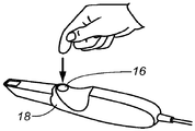
도 1a를 참조하면, 프로브(probe)의 형태를 갖는 구강내 카메라(18)를 포함하는 하나 이상의 치아(20)의 비디오 및 등가선 이미징을 위한 구강내 이미징 장치(10)가 도시된다. 상기 카메라(18)는 유선 또는 무선 데이터 통신 채널을 통해, 투사된 프린지 패턴으로부터 이미지를 획득하는 컴퓨터(40)와 통신한다. 상기 컴퓨터(40)는 이미지를 프로세싱하고 데이터 파일로서 저장될 수 있고 디스플레이(42) 상에 디스플레이되는 출력 이미지 데이터를 제공한다.Referring to FIG. 1A, an
도 1c의 투시도는 핸드헬드 용도로 설계되고 비디오 및 등가선 이미징 능력을 갖는 구강내 카메라(18)를 도시한다. 도시된 실시예에서, 카메라(18)는 전력 케이블(C2)과 연결된 데이터 케이블(C1)을 가진다. 데이터 케이블(C1)은 이미지 프로세싱, 저장, 및 디스플레이 기능을 위해 컴퓨터(40)로 연결된다.The perspective view of FIG. 1C illustrates an
도 1d 및 1e는 등가선 이미징을 위한 수동 모드 또는 자동 모드를 선택하기 위해 발동 가능한 선택적 스위치(16)의 운영자 선택을 도시한다. 자동 모드에서, 카메라는 운영자로부터의 특정 명령 없이 구조광 이미지를 지속적으로 캡처한다. 수동 모드에서, 운영자는 각각의 등가선 이미지 캡처에 대한 명령을 제공하고, 그렇지 않은 경우, 구조광 조명 및 캡처가 개시되지 않는다.1D and 1E illustrate the operator selection of an
도 2a에 도시된 바와 같이, 카메라(18)는 삽도 B에서 도시되는 바와 같이 치아(20)의 표면을 따르는 선(58) 또는 그 밖의 다른 특징부의 발산된 패턴(54)을 스캔하는 투사기(projector)를 포함한다. 그 후 카메라(18)는 스캔 동안 이미지를 주기적으로 캡처하여 치아 표면에 대한 등가선 정보를 나타내도록 조합될 수 있는 하나 이상의 이미지를 획득할 수 있다. 또한 반사율 이미지를 이용하는 표준 비디오 이미징 또는 그 밖의 다른 유형의 이미징, 가령, 형광 이미징을 제공하는 본 발명의 등가선 이미징 구성요소가 카메라에 포함될 수 있다.2A, the
스캔 패턴, 가령, 도 2b에 나타난 광의 고르게 이격된 평행하는 선들(84)의 패턴이 여러 방식 중 임의의 방식으로 생성될 수 있다. 본 발명의 하나의 실시예에 따르면, 2차원 표면의 일부분에 걸쳐 단일 레이저 다이오드로부터의 광 빔을 스캔함으로써 패턴(54)이 형성된다. 하나의 스캔이 길이 방향 L로 광점을 이동시키며, 또 다른 스캔이 다음 스캔 라인을 위해 광원의 위치를 길이 L에 직교하는 폭 거리 w만큼 증분시킨다. 카메라(18)에 동력이 공급되는 한, 스캔은 연속일 수 있으며, 이때 스캔된 패턴은 운영자에 의해 명령될 때 또는 이미징 시스템에 의해 자동으로 개시될 때만 캡처된다. 본 발명의 대안적 실시예에 따르면, 카메라 움직임이 중단될 때만, 심지어 운영자 명령어 입력에 의해 개시될 때 스캔이 생성되고 캡처된다. 스캐닝을 위해 가시 광이 사용되는 경우 스캔되는 광의 스펙트럼 특성이 비디오 이미지 내에서 지각될 수 있다. 본 발명의 대안적 실시예에 따르면, 가시 범위 밖의 광이 등가선 스캐닝을 위해 사용된다. 특정 치아에 대한 스캐닝된 패턴, 가령, 도 2b의 스캔되는 선의 패턴의 완전한 패턴을 획득하기 위해 하나 이상의 이미지가 캡처되고 조합될 필요가 있을 수 있다. The scan pattern, e.g., the pattern of evenly spaced
스캔 패턴의 요구되는 이미지가 획득되면, 표면 이미징 분야의 기술자에게 잘 알려진 계산 기법을 이용해 등가선 이미지가 형성될 수 있다. 도 2c는 치아(20)의 모델 상에 선(84)의 투사되는 패턴(54)을 도시한다. 예를 들어, 도 2d는 광의 평행하는 선들의 패턴을 이용해 형성되는 등가선 이미지(92)를 도시한다. Once the required image of the scan pattern is obtained, an equivalent line image may be formed using a computational technique well known to those skilled in the field of surface imaging. 2C shows the projected
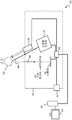
도 3의 개략적 블록도를 참조하면, 구조광 조명을 이용해 치아(20)로부터 표면 등가선 정보를 획득하기 위한 구강내 이미징 장치(10)의 하나의 실시예가 상세하게 나타난다. 카메라(18)에서, 구조광을 프린지 패턴 조명으로서 형성하고 따라서 형성된 구조광을 조명 경로(86)를 따르는 빔 방향을 갖는 치아(20)로의 입사광으로서 투사하기 위해 프린지 패턴 생성기(12)에 동력이 공급된다. 프린지 패턴 조명은 간섭 광의 좁은 빔을 제공하기에 유리한 레이저로부터 올 수 있다. 레이저는 레이저 다이오드일 수 있다. 대안적으로, 프린지 패턴 조명은 공간 광 변조기, 가령, 마이크로거울 어레이, 액정 장치(LCD) 또는 또 다른 광 변조기를 이용하는 발광 다이오드(LED) 또는 그 밖의 다른 솔리드-스테이트 광원으로부터 온다. 패터닝된 광이 치아(20) 표면을 따라 스캔된다. 치아(20)로부터 반사되고 산란되는 광이 이미징 렌즈(22)를 통해 검출기(30)로 제공된다. 검출기(30)는 이미징 렌즈(22)의 이미지 평면에서 검출 경로(88)를 따라 배치된다. 검출기(30)는 비디오 이미지와 구조광 이미지 모두를 획득하도록 사용될 수 있다. 제어 로직 프로세서(34)가 검출기(30)로부터 피드백 정보를 수락하고, 이 데이터 및 그 밖의 다른 데이터에 응답하여, 패턴 생성기(12)의 동작을 개시하도록, 가령, 투사된 이미지의 위치를 변경하고 주기적으로 이미지를 캡처하도록 발동될 수 있으며, 이는 차후 더 상세히 기재된다.Referring to the schematic block diagram of FIG. 3, one embodiment of an
도 3에 나타난 본 발명의 실시예에서, 패턴 생성기(12) 및 조명원(94)이 조명 경로(86)를 따르는 실질적으로 평행인 출력 축을 가진다. 선택적 운영자 스위치(16)에 의해, 수동 또는 자동에 대해 모드 설정이 조절될 수 있으며, 이는 차후 더 상세히 기재된다. In the embodiment of the invention shown in Figure 3, the
프린지 투사 이미징을 위한 제어 로직 프로세서(34)의 기능이 프린지 생성기(12)로부터의 프린지 패턴의 생성의 제어와, 등가선 이미징을 위한 적절한 타이밍에 따라 이미지를 캡처하기 위한 검출기(30)의 트리거를 포함한다. 제어 로직 프로세서(34)는 컴퓨터, 마이크로프로세서, 또는 프로그램된 명령을 실행하는 그 밖의 다른 특화된 로직 프로세싱 장치일 수 있다. 제어 로직 프로세서(34)는 디스플레이(42)를 갖는 컴퓨터(40)와 신호 통신한다. 컴퓨터(40)는 치아(20)의 비디오 및 등가선 이미지 콘텐츠의 디스플레이를 위해 디스플레이(42)와 신호 통신한다.The function of the
컴퓨터(40)는 검출기(30) 및 제어 로직 프로세서(34)에 의해 획득된 데이터를 이용하는 이미지 프로세싱 기능의 적어도 일부를 수행하여, 치아(20)의 표면 등가선 및 특징부를 보여주는 이미지를 제공할 수 있다. 다양한 제어 로직 및 이미징 기능이 제어 로직 프로세서(34) 또는 컴퓨터(40)에 의해 수행될 수 있거나 이들 제어 로직 장치들 간에 공유될 수 있음을 주지해야 한다. 예를 들어, 컴퓨터(40)는 움직임 검출을 위한 이미지 분석 기능을 수행하고 프린지 투사 이미징이 진행될 수 있는지 여부를 가리키는 움직임 신호 또는 신호들을 제공할 수 있다. 대안예로서 추가 컴퓨터 장치가 등가선 분석 및 디스플레이를 위한 다양한 계산 기능을 지원하도록 사용될 수 있다.The
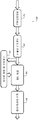
도 4의 로직 흐름도가 등가선 이미징을 위한 구강내 카메라 동작의 수동 및 자동 모드를 위한 동작 단계를 나타낸다. 선택 단계(S100)에서, 운영자는 등가선 이미지가 획득되는 모드를 결정하는 모드 선택을 한다. 도 3의 블록도를 다시 참조하면, 모드 선택은 스위치(16)를 이용해 만들어질 수 있다. 운영자는 수동 모드 또는 자동 모드를 선택한다. 수동 모드에서, 위치설정 단계(S110)에서, 운영자는 이미지 획득을 위해 관심 치아(또는 치아들) 근방에 카메라를 위치설정한다. 캡처 개시 단계(S120)에서, 운영자는, 가령, 구강내 카메라 상의 버튼 또는 컨트롤을 클릭함으로써 등가선 이미지를 캡처하기 위한 명령을 입력한다. 이에 응답하여, 카메라는 투사 단계(S130)를 실행하고 구조광 패턴을 치아 표면 상으로 투사하고, 캡처 단계(S140)를 실행하여 투사된 패턴의 이미지를 획득할 수 있다. 운영자는 재위치설정 단계(S150)에서 현재의 관심 치아 또는 또 다른 치아에 대한 추가 이미지 획득을 위해 시퀀스를 반복하기 위해 카메라를 재위치설정한다. 단계(S120, S130, S140, 및 S150)가 필요에 따라 반복된다. The logic flow diagram of FIG. 4 shows the operational steps for manual and automatic mode of intraoral camera operation for equivalent line imaging. In the selection step SlOO, the operator makes a mode selection to determine the mode in which the equivalent line image is obtained. Referring back to the block diagram of FIG. 3, the mode selection may be made using the
도 4의 우측이 자동 모드를 위한 동작의 대안적 시퀀스를 나타낸다. 위치설정 단계(S210)는 운영자가 카메라를 위치설정할 때 실행된다. 위치설정 단계(S210) 동안 비디오 이미지가 연속적으로 획득되고 디스플레이된다. 프레임 비교 단계(S220)에서 2개의 연속하는 (가령, 최근 및/또는 순차적인) 비디오 이미지 프레임이 비교되어, 카메라 움직임의 상대적 양을 결정할 수 있으며, 이는 예를 들어 차후 더 상세히 기재된다. 제어 로직 프로세서(34) 또는 대안적으로 컴퓨터(40)(도 3)로부터의 움직임 신호에 따라 카메라가 관심 치아와 관련하여 고정된 위치에서 정지 상태인 것으로 확정될 때 동작이 진행된다. 투사 단계(S230)에서 구조광 패턴이 투사되고 캡처 단계(S240)에서 이미지가 즉시 캡처된다. 등가선 이미징을 위해 이미지 획득을 계속하기 위해, 재위치설정 단계(S250)가 실행되며, 여기서 운영자는 현재 관심 치아의 다른 부분 또는 상이한 치아로 위치설정하도록 카메라를 이동시킨다. 단계(S210, S220, S230, S240, 및 S250)가 필요에 따라 반복된다.The right side of FIG. 4 shows an alternative sequence of operations for the automatic mode. The positioning step S210 is executed when the operator positions the camera. During the positioning step S210, the video image is continuously acquired and displayed. In the frame comparison step S220, two consecutive (e.g., recent and / or sequential) video image frames may be compared to determine the relative amount of camera motion, which will be described in more detail below, for example. Operation proceeds according to the motion signal from the
구조광 패턴은 관심 치아의 일부분에 대한 구강내 카메라의 단일 위치로부터 취해진 가변 프린지 패턴 조명에 의한 등가선 이미지의 세트를 포함할 수 있다. 예를 들어, 등가선 이미지의 세트는 등가선 이미지의 세트에 대응하는 관심 치아의 상기 일부분의 단일 3D 뷰를 생성하도록 사용될 수 있다. 하나의 실시예에서, 카메라가 정지 상태를 유지하는 동안 등가선 이미지의 전체 세트가 취해지거나(가령, 단계(S220) 동작) 치아의 일부분의 단일 3D 뷰가 바람직하게 생성되지 않는다. 하나의 실시예에서, 치아의 일부분의 복수의 단일 3D 뷰가 도 2d에 나타난 예시적 치아 표면을 생성하도록 사용된다. The structured light pattern may comprise a set of equivalent line images by variable fringe pattern illumination taken from a single location of the intraoral camera for a portion of the tooth of interest. For example, a set of equivalent line images can be used to create a single 3D view of the portion of interest that corresponds to a set of equivalent line images. In one embodiment, the entire set of equivalent line images is taken (e.g., step S220) while the camera remains stationary, and a single 3D view of a portion of the tooth is not preferably created. In one embodiment, a plurality of single 3D views of a portion of a tooth are used to create the exemplary tooth surface shown in Figure 2D.
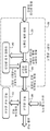
도 4를 참조하면, 단계(S210, S220, S230, S240, 및 S250)의 자동 모드가 비디오 이미지 데이터를 이용하여 카메라가 정확한 등가선 이미징을 위한 위치에서, 합리적으로 정지상태인지 여부를 결정할 수 있다. 도 5의 논리 흐름 다이어그램이 본 발명의 하나의 실시예에 따르는 자동 모드에서의 자동 모션 검출 및 프린지 패턴 이미지 캡처를 위한 예시적 데이터 핸들링 단계를 보여준다. 비디오 이미지 캡처 단계(S300)에서, 구강내 카메라는 제1 비디오 프레임을 획득한다. 가장자리 검출 단계(S310)에서 치아 가장자리가 검출된다. 제2 비디오 이미지 캡처 단계(S320)에서, 차후 비디오 프레임(가령, 다음 비디오 프레임)이 획득된다. 가장자리 검출 단계(S330)에서 이 제2 비디오 프레임에 대한 치아 가장자리가 검출된다. 그 후 비교 단계(S340)가 제1 비디오 이미지 프레임과 제2 비디오 이미지 프레임 간 대응하는 가장자리 위치를 비교한다. 결정 단계(S350)에서, 이 비교는 카메라가 이동 중인지 여부를 결정한다. 과도한 카메라 움직임은 다음 단계에서의 등가선 이미지 투사 및 캡처를 막을 수 있다. 과도한 움직임이 있을 때, 활동이 단계(S300)로 복귀하여 이미지 획득 및 평가를 반복할 수 있다. 다른 한편으로는, 비교 단계(S340)가 카메라가 실질적으로 정지 위치에 있다고 가리키는 경우, 결정 단계(S350)는 구조광 패턴을 관심 치아 상으로 투사하는 투사 단계(S360)의 실행을 위해 이 결과를 제공한다. 캡처 단계(S370)는 투사된 구조광 패턴의 하나 이상의 이미지를 캡처하고, 상기 이미지는 디스플레이 단계(S390)에서 선택적으로 디스플레이된다. 그 후 등가선 이미지 생성 단계(S380)가 캡처된 프린지 패턴 이미지를 이용해 치아의 등가선 이미지를 형성한다. 디스플레이 단계(S390)에서 상기 등가선 이미지가 디스플레이된다.Referring to FIG. 4, the automatic mode of steps S210, S220, S230, S240, and S250 may use video image data to determine whether the camera is reasonably stationary at a location for accurate equivalent line imaging . The logic flow diagram of Figure 5 shows an exemplary data handling step for automatic motion detection and fringe pattern image capture in an automatic mode in accordance with one embodiment of the present invention. In the video image capture step S300, the intraoral camera acquires the first video frame. The tooth edge is detected in the edge detection step (S310). In the second video image capture step S320, a subsequent video frame (e.g., the next video frame) is obtained. In the edge detection step (S330), the tooth edge for this second video frame is detected. The comparison step S340 then compares the corresponding edge positions between the first video image frame and the second video image frame. In decision step S350, this comparison determines whether the camera is moving. Excessive camera movement can prevent projecting and capturing equivalent line images in the next step. When there is excessive movement, the action may return to step S300 to repeat image acquisition and evaluation. On the other hand, if the comparing step S340 indicates that the camera is substantially in the rest position, then the determining step S350 is to determine the result of the projecting step S360 for projecting the structured light pattern onto the tooth of interest to provide. The capture step S370 captures one or more images of the projected structured light pattern, and the image is selectively displayed in the display step S390. An equivalent line image generation step (S380) then forms an equivalent line image of the tooth using the captured fringe pattern image. In the display step S390, the equivalent line image is displayed.
본 발명의 대안적 실시예에 따라, 자동 모드 이미지 캡처가 카메라(18)의 운영자와의 추가적인 상호대화를 포함한다. 단계(S220)에서 제1 및 제2 비디오 이미지 프레임이 어떠한 유의미한 카메라 움직임도 보이지 않는 경우, 패턴 투사 단계(S230) 및 캡처 단계(S240)가 실행되도록 패턴 투사 및 이미지 캡처를 위한 운영자 명령이 활성화된다. 운영자는 버튼 누름 시의 이미지 캡처를 획득한다. 그러나 카메라(18) 움직임이 지나치게 클 때, 지각되는 카메라 움직임이 지정 임계값 미만으로 감소될 때까지 단계(S230 및 S240) 중 하나 또는 둘 모든 단계가 비활성화될 수 있다.In accordance with an alternative embodiment of the present invention, the automatic mode image capture includes additional interaction with the operator of the
하나의 실시예에서, 투사 단계(S360)에서의 구조광 패턴은, 관심 치아(또는 관심 치아의 일부분)에 대한 단일 배향으로부터 취해진 일정한 또는 가변 프린지 패턴 조명에 의한 등가선 이미지(가령, 4개, 8개 또는 그 이상의 등가선 이미지)의 세트를 포함할 수 있고, 등가선 이미지의 세트는 캡처 단계(S370)에서 캡처된다. 예를 들어, 등가선 이미지 생성 단계(S380)에서 디스플레이 단계(S390)에서 디스플레이될 수 있는 등가선 이미지의 세트에 대응하는 관심 치아의 일부분에 대한 단일 3D 뷰를 생성하도록 등가선 이미지의 세트가 사용될 수 있다. 하나의 실시예에서, 디스플레이 단계(S390)에서 하나 이상 또는 전체 세트의 등가선 이미지가 디스플레이될 수 있다. 하나의 실시예에서, 치아(또는 치아들)의 일부분에 대한 복수의 단일 3D 뷰가 도 2d에 도시된 이러한 예시적 치아 표면을 생성하도록 사용된다.In one embodiment, the structured light pattern in the projection step S360 may include an equivalent line image (e.g., four, five, or six) by constant or variable fringe pattern illumination taken from a single orientation for a tooth of interest (or a portion of the tooth of interest) Eight or more equivalent line images), and a set of equivalent line images is captured in capture step S370. For example, a set of equivalent line images may be used to create a single 3D view of a portion of the tooth of interest that corresponds to a set of equivalent line images that can be displayed in display step S390 in an equivalent line image creation step (S380) . In one embodiment, one or more or all sets of equivalent line images may be displayed in display step S390. In one embodiment, a plurality of single 3D views of a portion of a tooth (or teeth) are used to produce this exemplary tooth surface shown in Figure 2D.
비교되는 제1 비디오 이미지 프레임과 제2 비디오 이미지 프레임이 시간상 인접할 때, 즉, 제2 비디오 이미지 프레임이 제1 비디오 이미지 프레임에 바로 이어서 캡처될 때 도 5와 관련하여 기재된 기법을 이용한 모션 검출이 가장 잘 동작함을 주지해야 한다. 대안적으로, 제2 비디오 프레임은 적어도 제1 비디오 이미지 프레임의 셋 이하의 비디오 프레임 내에 있을 수 있다. Motion detection using the technique described with reference to Figure 5 when the first video image frame and the second video image frame being compared are time-adjacent, i.e., when the second video image frame is captured immediately following the first video image frame It should be noted that it works best. Alternatively, the second video frame may be within at least three video frames of the first video image frame.
구강내 카메라(18)의 위치가 변화함에 따라, 등가선 특징화를 위해 요구되는 프린지 투사 이미지(들)의 상대적 위치(들)가 또한 변화할 수 있다. 카메라(18) 소프트웨어가 위치 변화를 검출할 수 있고, 움직임의 방향 및 크기에 따라, 다음 이미지 캡처에 대한 투사된 프린지 패턴 조명의 위치를 편이시킴으로써 검출된 위치 변화의 일정 양을 보상할 수 있다. 공간 위치 변화를 측정하기 위한 기법 및 검출된 위치 변화에 따라 투사된 광 패턴의 위치를 조절하기 위한 방법이 등가선 이미징 분야의 기술자들에게 알려져 있다. 예를 들어 이미지 변형(image deformation)을 위해 일상적으로 사용되는 기법이 이 문제에 적용될 수 있다. As the position of the
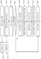
도 6의 논리적 흐름도가 구강내 카메라(18)를 지원하는 소프트웨어의 기능적 구성요소를 보여주며, 여기서 기능적 구성요소들은 구조광 이미지 캡처를 지원하기 위해 비디오 이미지 콘텐츠를 프로세싱하는 데 사용된다. 이벤트 검출기(60)에서, 장면 변화 검출기(62)는 비디오 프레임을 샘플링하고, 이를 프로세싱하여 가장자리를 검출하고, 이전 비디오 프레임에 비교하여, 카메라가 정지 상태인지 또는 움직이는 중인지를 결정할 수 있다. 결과가 각각의 프로세싱된 프레임을 저장하는 이벤트 버퍼 관리자(64) 및 정지 상태인지 또는 움직이는 상태를 가리키는 이벤트 생성기(66)로 이동한다. 액션 생성기(action generator)(68)가 소프트웨어 로직의 현재 상태를 기초로 하나 이상의 최종 액션 명령을 생성한다. 액션 버퍼 관리자(70)는 등가선 이미징 획득에 대한 정보를 기록한다. The logical flow diagram of FIG. 6 shows the functional components of the software that support the
도 7은 이벤트 검출기(60)의 구성요소를 더 상세히 나타낸다. 프리프로세서(preprocessor)(72)에서, 더 효과적인 프로세싱을 위해 각각의 입력 비디오 프레임이 가령, 더 낮은 해상도로 크기조정(scale)됨으로써 필터링되고 리사이징된다. 그 후 가장자리 추출기(74)가 크기조정되고, 프로세싱된 비디오 프레임을 프로세싱하여 가장자리를 검출할 수 있다. 가장자리 검출은 이미지 프로세싱 분야에서 잘 알려져 있으며, 예를 들어 가장자리 세부사항을 강조하는 복수의 디지털 필터 중 임의의 것을 이용한다. 가장자리 검출을 위한 알고리즘 방식들 중에 이른바 캐니 가장자리 검출(Canny edge detection), 가버 필터(Gabor filter), 및 예를 들어, 차등 지오메트리를 이용하는 이미지 구배를 분석하고 프로세싱하는 다양한 방법이 있다. 본 발명의 하나의 실시예에 따르면, 가우시안 공간 필터링의 2-D 편차가 각각의 이미지 프레임에 대한 이진 가장자리 맵(binary edge map)을 얻도록 사용될 수 있다.7 shows components of the
도 7에 도시된 프로세싱을 계속 이어서, 챔퍼 매칭 프로세스(chamfer matching process)(78)가 가장자리 검출을 각각의 이미지와 가장자리 맵 버퍼 관리자(76)로부터 획득된 바로 이전 이미지에 대해 비교하여 카메라 움직임을 추정할 수 있다. 그 후 시간 필터링/결정 프로세스(80)가 카메라 위치가 정지 상태인지 여부 또는 인지할 수 있는 카메라 움직임이 있는지 여부를 결정한다. 시간 필터링은 가령 무한 임펄스 응답(IIR) 필터를 이용할 수 있다. Continuing with the processing shown in FIG. 7, a
도 8a는 프리프로세싱 및 가장자리 검출 이전의 예시적인 필터링된 치아 이미지(56)를 도시한다. 도 8b는 필터링된 치아 이미지로부터 생성되는 예시적 가장자리 맵(52)을 도시한다. 8A shows an exemplary filtered
챔퍼 매칭은 이미지들 간 가장자리 상관을 위한 메트릭을 제공하기 위한 잘 알려진 기법이다. 동일한 대상의 2개의 가장자리 이미지가 주어지면, 챔퍼 매칭이 각각의 가장자리 맵 간 최상 정렬을 찾기 위해 다양한 기법을 이용한다. 가장자리 정렬을 위한 효과적이고 강건한 챔퍼 매칭이 기준 이미지 및 시험 이미지 상의 가장자리 포인트의 2개의 세트 간 일반화된 간격을 감소 또는 최소화할 수 있다. 챔퍼 매칭에 대한 참조가 Ming-Yu Liu, Oncel Tuzel, Ashok Veeraraghavan, 및 Rama Chellappa에 의한 제목 "Fast Directional Chamfer Matching", Proceedings of the IEEE Conference on Computer Vision 및 Pattern Recognition ( CVPR'10 ), San Francisco, California June 2010, pp. 1696 - 1703에서 제공된다. Chamfer matching is a well known technique for providing a metric for edge correlation between images. Given two edge images of the same subject, chamfer matching uses various techniques to find the best alignment between each edge map. Effective and robust chamfer matching for edge alignment can reduce or minimize the generalized spacing between the reference image and the two sets of edge points on the test image. References to chamfer matching are described in Ming-Yu Liu, Oncel Tuzel, Ashok Veeraraghavan, and Rama Chellappa entitled " Fast Directional Chamfer Matching ", Proceedings of the IEEE Conference on Computer Vision and Pattern Recognition ( CVPR'10 ) California June 2010, pp. 1696-1703.
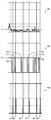
차이 맵(96)의 정렬된 그래프 부분 및 도 9에서 제공된 관련 그래프(98 및 100)가 움직임을 결정하기 위한 가장자리 맵의 비교를 위한 타이밍 관계를 보여준다. 그래프는 가령, 300개보다 많은 연속 비디오 프레임의 샘플링을 이용하기 위한 가장자리 검출 및 관련된 프로세싱을 보여준다. 이 프로세싱에 대해, 현재 비디오 프레임 및 이의 이전 비디오 프레임이 비교된다. 본 발명의 하나의 실시예에 따르면, 차이 맵(96)은 식별 가능한 가장자리 특징부에서의 대응하는 픽셀들 간 또는 인접한 이미지들에서의 특징부들 간 평균 유클리드 거리의 차이를 나타낸다. 이 거리가 지정 임계값(T1)을 초과할 때, 과도한 카메라 움직임이 지시되고, 따라서 등가선 이미지 투사 및 캡처가 평균 거리가 임계값(T1) 미만으로 낮아질 때까지 유예된다. 곡선의 하이 스파이크(high spike)가 연속하는 프레임들 간 큰 차이를 나타내는데, 이는 보통의 치아의 장면에서 카메라의 급속한 움직임이 발생하고 있음을 의미한다. IIR 필터에 의한 현재 프레임의 챔퍼 매칭에 대한 시간 필터링 후, 필터링된 챔퍼 매칭 값이 고정 임계값에 비교되어 그래프(98)에서 나타나는 바와 같이 이진 결정(binary decision)을 생성할 수 있다. 매칭 값이 임계값을 초과하는 경우, 결정은 '이동 중'이며, 그렇지 않은 경우, 결정은 '정지상태'이다. 현재 프레임 및 이전 N개의 프레임에 대한 결정이 합산된다. 충분한 프레임이 '이동 중'을 생성할 경우, 현재 프레임에 할당되는 최종 이벤트는 '이벤트-이동 중(Event-Moving)'이며, 그렇지 않은 경우, 할당되는 최종 이벤트는 '이벤트-정지상태(Event-Static)'이다.The sorted graph portion of the
그래프(98)는 차이 맵(96)의 차이 활동을, 예를 들어 이벤트(E1, E2, E3, E4, E5, 및 E6)로서 이진 표현으로 변환한다. 따라서 임계값(T2)에서의 이들 이벤트의 값이 활성 카메라 움직임의 주기를 가리킨다. 그래프(98) 값이 0일 때, 카메라 위치가 정지 상태로 여겨져, 등가선 이미징이 허용될 것이다. 상기 이벤트 변이가 가령 최종 액션(A1, A2, A3, A4, A5, 및 A6)을 보여주는 그래프(100)에서 나타난다. 최종 액션은 차이 맵(96)과 그래프(98)에서 반영되는 대응하는 계산을 기초로, 이미지 캡처가 획득될 수 있는 시간을 가리킨다. The
현재 프레임의 최종 이벤트가 액션 생성기(68), 이미지를 캡처할지 여부를 결정하기 위해 현재 이벤트와 이전 이벤트를 통합하는 프로세스로 입력된다. 정적 카메라 상태를 가리키는 '이벤트-정지상태' 이벤트의 경우, '캡처 액션(Capture Action)'이 생성된다. 충분한 개수의 연속 프레임이 '캡처 액션'을 출력할 때, '캡처 액션'은 최종적으로 현재 프레임에 대해 출력된다. 그 후 구강내 카메라가 등가선 이미지를 투사하고 캡처하기 위해 트리거된다. 덧붙여, 이전 '캡처 액션'이 성공적인 캡처를 생성하지 않았는 경우, 그 밖의 다른 추가 '캡처 액션' 명령어가 출력된다. 저장된 캡처 액션 이벤트의 개수 및 관련 이미지 핸들링 파라미터가 카메라에 대해 지정되고, 대안적으로, 이미징 상태 또는 운영자 선호에 따라 달라질 수 있다.The final event of the current frame is input to the
본 발명의 대안적 실시예에 따르면, 이미지 캡처 시퀀스는 스캔 이미징 시퀀스 동안 환자 움직임을 검출하기 위한 로직을 포함한다. 움직임 검출이 다양한 방식으로, 가령, 이미징 사이클 동안 반복되는 투사 및 동일 이미지 콘텐츠의 캡처에 의해 수행될 수 있다. According to an alternative embodiment of the present invention, the image capture sequence comprises logic for detecting patient movement during a scan imaging sequence. Motion detection can be performed in various ways, for example, by capturing the same image content and projection that is repeated during the imaging cycle.
그 후 투사된 패턴(54)의 획득된 이미지를 기초로, 도 2d의 예시에서 나타난 바와 같이 컴퓨터(40)가 치아에 대한 등가선 정보를 생성한다.Based on the acquired image of the projected
본 명세서에 기재된 실시예에서의 검출기(30)는 복수의 유형의 이미지 감지 어레이 중 임의의 것일 수 있다. 검출기(30)는 가령 CMOS(complementary metal oxide semiconductor) 이미징 센서 또는 CCD(charge-coupled device) 센서일 수 있다. 또한 카메라 광소자는 투사 또는 검출 경로 내에 필터, 편광기, 및 그 밖의 다른 구성요소를 포함할 수 있다.The
본 발명의 하나의 실시예에서, 이미징 장치는 불편함이 거의 또는 전혀 없이 환자의 입 안에서 쉽게 위치설정될 수 있는 핸드-헬드 프로브의 형태로 패키징된다. In one embodiment of the invention, the imaging device is packaged in the form of a hand-held probe that can be easily positioned within the patient's mouth with little or no discomfort.
본 발명의 장치 및 방법을 이용하여 획득된 표면 등가선 이미지가 다양한 방식으로 프로세싱되고 사용될 수 있다. 등가선 데이터가 디스플레이되고 복원 구조물을 프로세싱하고 생성하기 위한 시스템에 입력되거나, 치기공 기술자 또는 그 밖의 다른 치기공 장치의 제작자의 작업을 검증하기 위해 사용될 수 있다. 이 방법은 어떤 조건 하에서 틀(impression)을 획득할 필요성을 감소시키거나 제거하는 시스템 또는 절차의 일부로서 사용되어, 치과 진료의 전체 비용을 감소시킬 수 있다. The surface equivalent line image obtained using the apparatus and method of the present invention can be processed and used in various ways. Equivalent line data may be displayed and input to a system for processing and generating restoration structures, or may be used to verify the operation of a manufacturer of a dental technician or other dental equipment. This method can be used as part of a system or procedure to reduce or eliminate the need to obtain an impression under certain conditions, thereby reducing the overall cost of the dental care.
따라서 이 방법 및 장치를 이용해 수행되는 이미징이 치과의에 의한 조절 또는 맞춤을 거의 또는 전혀 필요로 하지 않는 우수한 보철 장치 맞춤을 획득하는 데 도움이 될 수 있다. 또 다른 양태에서, 본 발명의 장치 및 방법이 치아, 지지 구조물, 및 물림(bite) 상태의 장기 추적을 위해 사용되어, 더 심각한 건강 문제를 진단하고 방지하는 데 도움이 될 수 있다. 결국, 이 시스템을 이용하여 생성된 데이터가 사용되어 환자와 치과의 간의 소통 및 치과의, 스태프, 치기공 시설 간 소통을 개선하는 데 도움이 될 수 있다. Thus, imaging performed using this method and apparatus can help to obtain good prosthetic device alignment that requires little or no dentist adjustment or alignment. In another aspect, the apparatus and method of the present invention may be used for long-term tracking of teeth, support structures, and bite conditions to help diagnose and prevent more serious health problems. Ultimately, data generated using this system can be used to help communicate between the patient and the dentist and improve communication between the dentist, staff, and institution.
바람직하게는, 본 발명의 장치 및 방법은 치아 표면용 특수 파우더의 사용 또는 그 밖의 다른 어떠한 임시 코팅의 도포를 요구하지 않으면서 치아 및 그 밖의 다른 치아 특징부의 3D 이미징을 위한 구강내 이미징 시스템을 제공한다. 하나의 실시예에서 시스템은 25-50 ㎛ 범위의 높은 해상도를 제안한다. Preferably, the apparatus and method of the present invention provides an intraoral imaging system for 3D imaging of teeth and other tooth features without requiring the use of special powders for tooth surfaces or application of any other temporary coatings do. In one embodiment, the system proposes a high resolution in the range of 25-50 [mu] m.
본 발명의 하나의 실시예에 따르면, 컴퓨터 프로그램이 전자 메모리로부터 액세스되는 이미지 데이터를 수행하는 저장된 명령을 이용한다. 이미지 프로세싱 분야의 기술자라면 알다시피, 본 발명의 실시예에서 이미징 시스템을 동작시키기 위한 컴퓨터 프로그램이 적합한 범용 컴퓨터 시스템, 가령, 개인 컴퓨터 또는 워크스테이션에 의해 사용될 수 있다. 그러나 본 발명의 컴퓨터 프로그램을 실행하기 위해 그 밖의 다른 많은 유형의 컴퓨터 시스템, 가령, 네트워크 연결된 프로세서의 배열이 사용될 수 있다. 본 발명의 방법을 수행하기 위한 컴퓨터 프로그램이 컴퓨터 판독형 저장 매체에 저장될 수 있다. 이 매체는, 예를 들어, 자기 저장 매체, 가령, 자기 디스크, 가령, 하드 드라이브 또는 이동식 장치 또는 자기 테이프, 광학 저장 매체, 가령, 광 디스크, 광 테이프, 또는 기계 판독형 광학 인코딩, 솔리드 스테이트 전자 저장 장치, 가령, 랜덤 액세스 메모리(RAM), 또는 리드 온리 메모리(ROM), 또는 컴퓨터 프로그램을 저장하도록 사용되는 그 밖의 다른 임의의 물리 장치 또는 매체를 포함할 수 있다. 본 발명의 방법을 수행하기 위한 컴퓨터 프로그램이 또한 인터넷 또는 그 밖의 다른 네트워크 또는 통신 매체에 의해 이미지 프로세서로 연결되는 컴퓨터 판독형 저장 매체 상에 저장될 수 있다. 해당 분야의 통상의 기술자라면 이러한 컴퓨터 프로그램 제품의 균등물이 또한 하드웨어로 구성될 수 있음을 쉽게 인지할 것이다.According to one embodiment of the invention, a computer program makes use of a stored instruction to perform image data accessed from an electronic memory. As one skilled in the art of image processing will appreciate, a computer program for operating an imaging system in an embodiment of the present invention may be used by a suitable general purpose computer system, such as a personal computer or workstation. However, many other types of computer systems, such as an array of networked processors, may be used to implement the computer program of the present invention. A computer program for carrying out the method of the present invention may be stored in a computer readable storage medium. The medium may be, for example, a magnetic storage medium, such as a magnetic disk, such as a hard drive or removable device or magnetic tape, an optical storage medium such as an optical disk, optical tape, or machine readable optical encoding, Storage devices, such as random access memory (RAM), or read only memory (ROM), or any other physical device or medium used to store computer programs. A computer program for carrying out the method of the present invention may also be stored on a computer readable storage medium connected to the image processor by the Internet or other network or communication medium. Those of ordinary skill in the art will readily recognize that equivalents of such computer program products may also be constructed in hardware.
본 발명의 맥락에서 "컴퓨터 액세스 가능 메모리"에 상응하는 용어 "메모리"가 이미지 데이터를 저장 및 조작하고, 가령, 데이터베이스를 포함하는 컴퓨터 시스템에 액세스 가능한 임의의 유형의 임시 또는 더 유지되는 데이터 저장 작업공간을 지칭할 수 있다. 메모리는 예를 들어, 장기 저장 매체, 가령, 자기 또는 광학 저장소를 이용하는 비휘발성일 수 있다. 대안적으로, 전자 회로, 가령, 마이크로프로세서 또는 그 밖의 다른 제어 로직 프로세서 장치에 의해 임시 버퍼 또는 작업공간으로서 사용되는 랜덤-액세스 메모리(RAM)를 이용해 메모리는 더 휘발성의 속성을 가질 수 있다. 가령, 디스플레이 데이터는 디스플레이 장치와 직접 연관된 임시 저장 버퍼에 저장되고 필요에 따라 주기적으로 재생되어 디스플레이되는 데이터를 제공하는 것이 일반적이다. 이 임시 저장 버퍼는 또한, 본 발명에서 사용될 때 일종의 메모리로 여겨진다. 또한 메모리는 계산 및 그 밖의 다른 프로세싱의 중간 및 최종 결과를 실행하고 저장하기 위한 데이터 작업공간으로서 사용된다. 컴퓨터 액세스 가능한 메모리는 휘발성, 비휘발성, 또는 휘발성과 비휘발성의 하이브리드 조합형일 수 있다.In the context of the present invention, the term "memory" corresponding to "computer accessible memory" refers to any type of temporary or more persistent data storage operation that stores and manipulates image data, It can refer to space. The memory may be non-volatile, for example using a long-term storage medium, such as a magnetic or optical storage. Alternatively, the memory may have a more volatile property using electronic circuitry, such as a random-access memory (RAM) used as a temporary buffer or work space by a microprocessor or other control logic processor device. For example, it is common for display data to be stored in a temporary storage buffer directly associated with the display device, and to provide data that is periodically reproduced and displayed as needed. This temporary storage buffer is also considered to be a kind of memory when used in the present invention. The memory is also used as a data work space for executing and storing intermediate and final results of computations and other processing. The computer-accessible memory may be volatile, nonvolatile, or a hybrid combination of volatile and nonvolatile.
본 발명의 컴퓨터 프로그램 제품이 잘 알려진 다양한 이미지 조작 알고리즘 및 프로세스를 이용할 수 있다. 본 발명의 컴퓨터 프로그램 제품 실시예는 구현을 위해 유용한 본 명세서에 특정하게 도시되거나 기재되지 않은 알고리즘 및 프로세스를 실현할 수 있음이 추가로 이해될 것이다. 이러한 알고리즘 및 프로세스는 이미지 프로세싱 분야의 통상의 지식 내에 있는 종래의 유틸리티를 포함할 수 있다. 이러한 알고리즘 및 시스템의 추가 양태, 및 이미지를 생성하고 그 밖의 다른 방식으로 프로세싱하거나 본 발명의 컴퓨터 프로그램 제품과 공동-동작하기 위한 하드웨어 및/또는 소프트웨어가 본 명세서에 특정하게 나타나거나 기재되지 않았으며, 공지된 이러한 알고리즘, 시스템, 하드웨어, 구성요소 및 요소로부터 선택될 수 있다.The computer program product of the present invention may utilize a variety of well known image manipulation algorithms and processes. It will further be understood that the computer program product embodiments of the present invention may implement algorithms and processes not specifically shown or described herein which are useful for implementation. Such algorithms and processes may include conventional utilities within the ordinary knowledge of the field of image processing. Additional aspects of such algorithms and systems, and hardware and / or software for generating and processing images and otherwise cooperating with a computer program product of the present invention are not specifically shown or described herein, May be selected from such known algorithms, systems, hardware, components and elements.
본 발명이 상세히 기재되었고, 적합한 또는 현재 선호되는 실시예를 구체적으로 참조하여 기재됐을 수 있지만, 본 발명의 사상과 범위 내에서 변형예 및 수정예가 가능함이 이해될 것이다. 따라서 현재 개시된 실시예는 모두 예시로 간주되며 제한이 아니다. 본 발명의 범위는 특허청구범위에 의해 지시되고 이의 균등물의 의미 및 범위 내에 있는 모든 변경이 여기에 포함되는 것으로 의도된다. While the invention has been described in detail and with reference to specific or present preferred embodiments thereof, it will be understood that modifications and variations are possible within the spirit and scope of the invention. Accordingly, the presently disclosed embodiments are all considered to be illustrative and not restrictive. It is intended that the scope of the invention be construed as including all such changes which are dictated by the scope of the claims and which are within the meaning and range of equivalents thereof.
본 발명이 하나 이상의 구현예와 관련하여 기재되었지만, 대안예 및/또는 수정예가 특허청구범위의 사상과 범위 내에서 이뤄질 수 있다. 덧붙여, 본 발명의 특정 특징부가 복수의 구현예 중 하나와 관련되어 개시되었을 수 있지만, 이러한 특징부는 임의의 특정 기능에 대해 바람직하거나 유리할 수 있을 때 그 밖의 다른 구현예의 하나 이상의 그 밖의 다른 특징부와 조합될 수 있다. 용어 "중 적어도 하나"는 나열되는 아이템들 중 하나 이상이 선택될 수 있음을 의미하도록 사용된다. 용어 "약"은, 변경이 도시된 실시예에서의 프로세스 또는 구조물의 부적합성을 야기하지 않는 한, 나열된 값이 다소 변경될 수 있음을 지시한다. 마지막으로, "예시적"은 기재가 이상적임을 의미하기보다는 예시로서 사용됨을 나타낸다. 본 발명의 그 밖의 다른 실시예가 명세서의 고려 및 본 명세서에 개시된 본 발명의 실시로부터 해당 분야의 통상의 기술자에게 자명할 것이다. 명세서 및 예시들은 단지 예로서 고려되고 본 발명의 사상은 다음의 특허청구범위에 의해 지시된다.While the invention has been described in conjunction with one or more embodiments, alternatives and / or modifications may be made within the spirit and scope of the claims. In addition, while certain features of the invention may have been disclosed in connection with any one of a plurality of implementations, such features may be advantageous or advantageous over any particular feature, Can be combined. The term "at least one of" is used to mean that one or more of the listed items can be selected. The term " about "indicates that the values listed may vary somewhat, unless the alteration causes incompatibility of the process or structure in the illustrated embodiment. Finally, "exemplary" indicates that the description is used as an example rather than an ideal. Other embodiments of the invention will be apparent to those skilled in the art from consideration of the specification and practice of the invention disclosed herein. The specification and examples are considered by way of example only and the spirit of the invention is indicated by the following claims.
Claims (16)
상기 방법은 컴퓨터에 의해 적어도 부분적으로 실행되며,
치아를 포함하는 제1 비디오 이미지 프레임을 획득하고 상기 제1 비디오 이미지 프레임을 프로세싱하여, 상기 제1 비디오 이미지 프레임 내 치아의 하나 이상의 가장자리를 검출하는 단계와,
치아를 포함하는 제2 비디오 이미지 프레임을 획득하고 상기 제2 비디오 이미지 프레임을 프로세싱하여, 상기 제2 비디오 이미지 프레임 내 치아의 하나 이상의 가장자리를 검출하는 단계와,
프로세싱된 제1 비디오 이미지 프레임과 제2 비디오 이미지 프레임 간 대응하는 가장자리 위치들을 비교하는 단계
에 의해 구강내 카메라의 움직임을 검출하는 단계와,
상기 카메라로부터 상기 치아 상으로 프린지 패턴 조명을 투사하고 상기 검출된 카메라 움직임에 따라 프린지 패턴의 하나 이상의 정지 이미지를 캡처 및 저장하는 단계를 포함하는
치아의 등가선 이미지를 획득하기 위한 방법.
CLAIMS What is claimed is: 1. A method for obtaining a contour image of a tooth,
The method is performed at least in part by a computer,
Obtaining a first video image frame comprising teeth and processing the first video image frame to detect one or more edges of the teeth in the first video image frame;
Obtaining a second video image frame comprising a tooth and processing the second video image frame to detect one or more edges of the teeth in the second video image frame;
Comparing corresponding edge positions between the processed first video image frame and the second video image frame
Detecting movement of the camera in the oral cavity by means of the camera,
Projecting fringe pattern illumination from the camera onto the tooth and capturing and storing one or more still images of the fringe pattern in accordance with the detected camera motion
A method for obtaining an equivalent line image of a tooth.
대응하는 가장자리 위치들을 비교하는 단계는 챔퍼 매칭 프로세스(chamfer matching process)를 이용하는 단계를 포함하는
치아의 등가선 이미지를 획득하기 위한 방법.
The method according to claim 1,
The step of comparing corresponding edge positions comprises using a chamfer matching process
A method for obtaining an equivalent line image of a tooth.
캡처된 하나 이상의 정지 이미지를 디스플레이하는 단계를 더 포함하는
치아의 등가선 이미지를 획득하기 위한 방법.
The method according to claim 1,
And displaying the captured one or more still images
A method for obtaining an equivalent line image of a tooth.
치아 표면을 따라 상기 투사된 프린지 패턴 조명의 위치를 이동시키는 단계와, 상기 카메라로부터 상기 치아 상으로 프린지 패턴 조명을 투사하고 상기 검출된 카메라 움직임에 따라 프린지 패턴의 하나 이상의 정지 이미지를 캡처 및 저장하는 단계를 반복하는 단계를 더 포함하는
치아의 등가선 이미지를 획득하기 위한 방법.
The method according to claim 1,
Moving the position of the projected fringe pattern illumination along a tooth surface; projecting fringe pattern illumination from the camera onto the tooth and capturing and storing one or more still images of the fringe pattern according to the detected camera movement Further comprising repeating steps
A method for obtaining an equivalent line image of a tooth.
상기 프린지 패턴의 하나 이상의 정지 이미지를 이용해 치아 표면의 3차원 이미지를 형성하고 디스플레이하는 단계를 더 포함하는
치아의 등가선 이미지를 획득하기 위한 방법.
The method according to claim 1,
Further comprising forming and displaying a three-dimensional image of the tooth surface using one or more still images of the fringe pattern
A method for obtaining an equivalent line image of a tooth.
상기 하나 이상의 정지 이미지를 자동으로 투사, 캡처, 및 저장하기 위한 운영자 명령을 수락하는 단계를 더 포함하는
치아의 등가선 이미지를 획득하기 위한 방법.
The method according to claim 1,
Further comprising accepting an operator command for automatically projecting, capturing, and storing the one or more still images
A method for obtaining an equivalent line image of a tooth.
요구되는 프린지 패턴 이미지를 계산하는 단계와, 자동으로 구강내 카메라 위치를 결정하고 카메라 위치가 변경될 때 투사 패턴 이미지를 캡처하는 단계를 더 포함하는
치아의 등가선 이미지를 획득하기 위한 방법.
The method according to claim 1,
Calculating the required fringe pattern image, automatically determining the intraoral camera position and capturing the projection pattern image when the camera position is changed
A method for obtaining an equivalent line image of a tooth.
상기 제1 비디오 이미지 프레임은 상기 제2 비디오 이미지 프레임에 시간상 인접한
치아의 등가선 이미지를 획득하기 위한 방법.
The method according to claim 1,
Wherein the first video image frame is temporally adjacent to the second video image frame
A method for obtaining an equivalent line image of a tooth.
대응하는 가장자리 위치들을 비교하는 단계는 프로세싱된 상기 제1 비디오 이미지 프레임과 상기 제2 비디오 이미지 프레임을 크기조정(scale)하는 단계를 포함하는
치아의 등가선 이미지를 획득하기 위한 방법.
The method according to claim 1,
Wherein comparing the corresponding edge positions comprises scaling the processed first video image frame and the second video image frame
A method for obtaining an equivalent line image of a tooth.
상기 프린지 패턴 조명은 레이저 광을 포함하는
치아의 등가선 이미지를 획득하기 위한 방법.
The method according to claim 1,
Wherein the fringe pattern illumination comprises a laser light
A method for obtaining an equivalent line image of a tooth.
대응하는 가장자리 위치들을 비교하는 단계는 적어도 하나의 유클리드 거리 값을 계산하는 단계를 포함하는
치아의 등가선 이미지를 획득하기 위한 방법.
The method according to claim 1,
Wherein comparing the corresponding edge positions comprises calculating at least one Euclidian distance value
A method for obtaining an equivalent line image of a tooth.
상기 방법은 컴퓨터에 의해 적어도 부분적으로 실행되며,
치아를 보여주는 제1 비디오 이미지 프레임을 획득하고 상기 제1 비디오 이미지 프레임을 프로세싱하여, 상기 치아의 하나 이상의 가장자리를 검출하는 단계와,
치아를 보여주는 제2 비디오 이미지 프레임을 획득하고 상기 제2 비디오 이미지 프레임을 프로세싱하여, 상기 치아의 하나 이상의 가장자리를 검출하는 단계와,
프로세싱된 제1 비디오 이미지 프레임과 제2 비디오 이미지 프레임 간 대응하는 가장자리 위치들을 비교하는 단계
에 의해 구강내 카메라 움직임을 검출하는 단계와,
레이저에 동력을 공급하고 프린지 패턴 조명을 상기 치아 상에 투사하며 상기 검출된 구강내 카메라 움직임에 따라 상기 투사된 프린지 패턴의 하나 이상의 정지 이미지를 캡처 및 저장하는 단계와,
상기 프린지 패턴의 하나 이상의 정지 이미지를 이용해 치아 표면의 3차원 이미지를 형성 및 디스플레이하는 단계를 포함하는
치아의 등가선 이미지를 획득하기 위한 방법.
CLAIMS 1. A method for obtaining an equivalent line image of a tooth,
The method is performed at least in part by a computer,
Obtaining a first video image frame showing a tooth and processing the first video image frame to detect one or more edges of the tooth;
Obtaining a second video image frame showing a tooth and processing the second video image frame to detect one or more edges of the tooth;
Comparing corresponding edge positions between the processed first video image frame and the second video image frame
Detecting camera movement in the mouth by means of a camera,
Powering the laser and projecting a fringe pattern illumination onto the tooth, capturing and storing one or more still images of the projected fringe pattern according to the detected intraoral camera movement,
And forming and displaying a three-dimensional image of the tooth surface using one or more still images of the fringe pattern
A method for obtaining an equivalent line image of a tooth.
대응하는 가장자리 위치들을 비교하는 단계는 챔퍼 매칭 프로세스를 이용하는 단계를 포함하는
치아의 등가선 이미지를 획득하기 위한 방법.
13. The method of claim 12,
Wherein comparing the corresponding edge positions comprises using a chamfer matching process
A method for obtaining an equivalent line image of a tooth.
상기 캡처된 하나 이상의 정지 이미지를 디스플레이하는 단계를 더 포함하는
치아의 등가선 이미지를 획득하기 위한 방법.
13. The method of claim 12,
Further comprising displaying the captured one or more still images
A method for obtaining an equivalent line image of a tooth.
대응하는 가장자리 위치들을 비교하는 단계는 프로세싱된 상기 제1 비디오 이미지 프레임과 상기 제2 비디오 이미지 프레임을 크기조정하는 단계를 포함하는
치아의 등가선 이미지를 획득하기 위한 방법.
13. The method of claim 12,
Wherein comparing the corresponding edge positions comprises resizing the processed first video image frame and the second video image frame
A method for obtaining an equivalent line image of a tooth.
상기 장치는
상기 치아의 비디오 또는 프린지 패턴 이미지에 대한 이미지 데이터를 획득하는 검출기와,
상기 치아의 등가선 이미징을 활성화하도록 발동 가능한 스위치와,
카메라 움직임을 나타내는 움직임 신호에 따라, 등가선 이미징을 위해 상기 치아 상으로 레이저 광 빔을 스캔하도록 동력 공급되는 프린지 패턴 생성기
를 포함하는 구강내 카메라와,
상기 검출기에 의해 획득되는 이미지 데이터를 수신하고 상기 치아의 등가선 이미지를 생성하기 위해 상기 구강내 카메라와 신호 통신하는 컴퓨터와,
상기 구강내 카메라의 내부 또는 컴퓨터 상에 있으며, 비디오 이미지 데이터에 따라, 상기 치아에 대한 카메라 움직임을 나타내는 상기 움직임 신호를 제공하는 제어 로직 프로세서와,
비디오 및 등가선 이미지의 디스플레이를 위해 컴퓨터와 신호 통신하는 디스플레이를 포함하는
치아를 이미징하기 위한 장치. An apparatus for imaging a tooth,
The device
A detector for obtaining image data for a video or fringe pattern image of the tooth;
A switch actuable to activate an equivalent line imaging of the tooth;
A fringe pattern generator that is powered to scan the laser light beam onto the tooth for equivalent line imaging in accordance with a motion signal representative of camera motion,
An intraoral camera,
A computer in signal communication with the intraoral camera to receive image data acquired by the detector and produce an equivalent line image of the tooth;
A control logic processor in the intraoral camera or on a computer for providing the motion signal indicative of camera motion for the tooth in accordance with video image data;
Video and a display for signal communication with a computer for display of an equivalent line image
A device for imaging a tooth.
Applications Claiming Priority (5)
| Application Number | Priority Date | Filing Date | Title |
|---|---|---|---|
| US201361845440P | 2013-07-12 | 2013-07-12 | |
| US61/845,440 | 2013-07-12 | ||
| US14/326,568 | 2014-07-09 | ||
| US14/326,568 US9675428B2 (en) | 2013-07-12 | 2014-07-09 | Video-based auto-capture for dental surface imaging apparatus |
| PCT/US2014/046061 WO2015006518A1 (en) | 2013-07-12 | 2014-07-10 | Video-based auto-capture for dental surface imaging apparatus |
Publications (1)
| Publication Number | Publication Date |
|---|---|
| KR20160030509A true KR20160030509A (en) | 2016-03-18 |
Family
ID=52277362
Family Applications (1)
| Application Number | Title | Priority Date | Filing Date |
|---|---|---|---|
| KR1020167000693A KR20160030509A (en) | 2013-07-12 | 2014-07-10 | Video-based auto-capture for dental surface imaging apparatus |
Country Status (7)
| Country | Link |
|---|---|
| US (1) | US9675428B2 (en) |
| EP (1) | EP3019117B1 (en) |
| JP (1) | JP6431535B2 (en) |
| KR (1) | KR20160030509A (en) |
| CN (1) | CN105358092B (en) |
| DK (1) | DK3019117T3 (en) |
| WO (1) | WO2015006518A1 (en) |
Families Citing this family (16)
| Publication number | Priority date | Publication date | Assignee | Title |
|---|---|---|---|---|
| US11363938B2 (en) * | 2013-03-14 | 2022-06-21 | Ormco Corporation | Feedback control mechanism for adjustment of imaging parameters in a dental imaging system |
| US9424653B2 (en) * | 2014-04-29 | 2016-08-23 | Adobe Systems Incorporated | Method and apparatus for identifying a representative area of an image |
| KR20170045232A (en) * | 2014-08-28 | 2017-04-26 | 케어스트림 헬스 인코포레이티드 | 3-d intraoral measurements using optical multiline method |
| US10074178B2 (en) * | 2015-01-30 | 2018-09-11 | Dental Imaging Technologies Corporation | Intra-oral image acquisition alignment |
| US9451873B1 (en) | 2015-03-06 | 2016-09-27 | Align Technology, Inc. | Automatic selection and locking of intraoral images |
| CN107257992B (en) * | 2015-03-09 | 2021-02-02 | 锐珂牙科技术顶阔有限公司 | Apparatus and method for texture mapping for dental 3D scanner |
| US20190231493A1 (en) * | 2016-06-20 | 2019-08-01 | Carestream Dental Technology Topco Limited | Dental restoration assessment using virtual model |
| CN113648088B (en) * | 2016-11-04 | 2023-08-22 | 阿莱恩技术有限公司 | Method and apparatus for dental imaging |
| US10282860B2 (en) * | 2017-05-22 | 2019-05-07 | Honda Motor Co., Ltd. | Monocular localization in urban environments using road markings |
| EP3648704A4 (en) * | 2017-07-04 | 2021-03-24 | Dentlytec G.P.L. Ltd. | Tracked dental measurement device |
| US10376149B2 (en) | 2017-07-11 | 2019-08-13 | Colgate-Palmolive Company | Oral care evaluation system and process |
| EP3768144A4 (en) * | 2018-03-21 | 2021-12-01 | CapsoVision, Inc. | Endoscope employing structured light providing physiological feature size measurement |
| US10996813B2 (en) * | 2018-06-29 | 2021-05-04 | Align Technology, Inc. | Digital treatment planning by modeling inter-arch collisions |
| CN109218707B (en) * | 2018-08-15 | 2020-09-04 | 苏州佳世达电通有限公司 | Oral scanning system and oral scanning method |
| WO2020037582A1 (en) * | 2018-08-23 | 2020-02-27 | Carestream Dental Technology Shanghai Co., Ltd. | Graph-based key frame selection for 3-d scanning |
| JP6941126B2 (en) * | 2019-03-18 | 2021-09-29 | 株式会社モリタ製作所 | Dental equipment and its control method |
Family Cites Families (18)
| Publication number | Priority date | Publication date | Assignee | Title |
|---|---|---|---|---|
| US5372502A (en) | 1988-09-02 | 1994-12-13 | Kaltenbach & Voight Gmbh & Co. | Optical probe and method for the three-dimensional surveying of teeth |
| DE4229466C2 (en) * | 1992-09-03 | 2001-04-26 | Kaltenbach & Voigt | Tooth measurement without calibration body |
| DE19829278C1 (en) | 1998-06-30 | 2000-02-03 | Sirona Dental Systems Gmbh | 3-D camera for the detection of surface structures, especially for dental purposes |
| US6532299B1 (en) | 2000-04-28 | 2003-03-11 | Orametrix, Inc. | System and method for mapping a surface |
| US20060127836A1 (en) * | 2004-12-14 | 2006-06-15 | Huafeng Wen | Tooth movement tracking system |
| US7312924B2 (en) | 2005-09-01 | 2007-12-25 | Richard G Trissel | Polarizing multiplexer and methods for intra-oral scanning |
| US20070086762A1 (en) | 2005-10-13 | 2007-04-19 | 3M Innovative Properties Company | Front end for 3D imaging camera |
| US8794962B2 (en) * | 2006-03-03 | 2014-08-05 | 4D Dental Systems, Inc. | Methods and composition for tracking jaw motion |
| US7702139B2 (en) * | 2006-10-13 | 2010-04-20 | Carestream Health, Inc. | Apparatus for caries detection |
| US8866894B2 (en) * | 2008-01-22 | 2014-10-21 | Carestream Health, Inc. | Method for real-time visualization of caries condition |
| US20100253773A1 (en) * | 2008-05-13 | 2010-10-07 | Oota Sadafumi | Intra-oral measurement device and intra-oral measurement system |
| DE102008054985B4 (en) * | 2008-12-19 | 2012-02-02 | Sirona Dental Systems Gmbh | Method and device for optical measurement of three-dimensional objects by means of a dental 3D camera using a triangulation method |
| EP2198780B1 (en) * | 2008-12-19 | 2018-01-31 | Sirona Dental Systems GmbH | Method and device for optical scanning of three-dimensional objects by means of a dental 3D camera using a triangulation method |
| KR101162439B1 (en) | 2010-05-20 | 2012-07-04 | 임용근 | A measurement apparatus for 3D scanner |
| US9436868B2 (en) | 2010-09-10 | 2016-09-06 | Dimensional Photonics International, Inc. | Object classification for measured three-dimensional object scenes |
| FR2979226B1 (en) * | 2011-08-31 | 2014-11-21 | Maxime Jaisson | METHOD FOR DESIGNING A DENTAL APPARATUS |
| DK2941220T3 (en) * | 2012-12-24 | 2022-02-07 | Dentlytec G P L Ltd | DEVICE AND METHOD OF SUBGINGIVAL MEASUREMENT |
| US20140199649A1 (en) | 2013-01-16 | 2014-07-17 | Pushkar Apte | Autocapture for intra-oral imaging using inertial sensing |
-
2014
- 2014-07-09 US US14/326,568 patent/US9675428B2/en not_active Expired - Fee Related
- 2014-07-10 EP EP14744716.3A patent/EP3019117B1/en active Active
- 2014-07-10 WO PCT/US2014/046061 patent/WO2015006518A1/en active Application Filing
- 2014-07-10 JP JP2016525471A patent/JP6431535B2/en not_active Expired - Fee Related
- 2014-07-10 DK DK14744716.3T patent/DK3019117T3/en active
- 2014-07-10 KR KR1020167000693A patent/KR20160030509A/en active IP Right Grant
- 2014-07-10 CN CN201480038676.8A patent/CN105358092B/en not_active Expired - Fee Related
Also Published As
| Publication number | Publication date |
|---|---|
| EP3019117A1 (en) | 2016-05-18 |
| EP3019117B1 (en) | 2019-10-16 |
| US9675428B2 (en) | 2017-06-13 |
| JP6431535B2 (en) | 2018-11-28 |
| CN105358092B (en) | 2017-08-18 |
| DK3019117T3 (en) | 2019-12-16 |
| JP2016529959A (en) | 2016-09-29 |
| US20150017598A1 (en) | 2015-01-15 |
| CN105358092A (en) | 2016-02-24 |
| WO2015006518A1 (en) | 2015-01-15 |
Similar Documents
| Publication | Publication Date | Title |
|---|---|---|
| EP3019117B1 (en) | Video-based auto-capture for dental surface imaging apparatus | |
| US8134719B2 (en) | 3-D imaging using telecentric defocus | |
| US10064553B2 (en) | Detection of a movable object when 3D scanning a rigid object | |
| US9314150B2 (en) | System and method for detecting tooth cracks via surface contour imaging | |
| US10278584B2 (en) | Method and system for three-dimensional imaging | |
| KR101395234B1 (en) | Method for acquiring three-dimensional images | |
| US11382559B2 (en) | Dental surface imaging apparatus using laser projection | |
| WO2017062044A1 (en) | Adaptive tuning of 3d acquisition speed for dental surface imaging | |
| CA2528824A1 (en) | Three-dimensional shape-measuring device | |
| US10463243B2 (en) | Structured light generation for intraoral 3D camera using 1D MEMS scanning | |
| JP2004309240A (en) | Three-dimensional shape measuring apparatus | |
| EP3195253B1 (en) | 3- d intraoral measurements using optical multiline method | |
| JP2015523108A (en) | How to measure dental conditions | |
| JP2018173338A (en) | Three-dimensional shape measuring method using scanning white interference microscope | |
| JP2021124429A (en) | Scanning measurement method and scanning measurement device | |
| JP6820516B2 (en) | Surface shape measurement method | |
| RU2522840C1 (en) | Electronic space scanning method | |
| JP2021060214A (en) | Measuring apparatus and measuring method |
Legal Events
| Date | Code | Title | Description |
|---|---|---|---|
| A201 | Request for examination | ||
| E701 | Decision to grant or registration of patent right |