KR20160018795A - Method for operating a heat pump arrangement, and heat pump arrangement - Google Patents
Method for operating a heat pump arrangement, and heat pump arrangement Download PDFInfo
- Publication number
- KR20160018795A KR20160018795A KR1020167000674A KR20167000674A KR20160018795A KR 20160018795 A KR20160018795 A KR 20160018795A KR 1020167000674 A KR1020167000674 A KR 1020167000674A KR 20167000674 A KR20167000674 A KR 20167000674A KR 20160018795 A KR20160018795 A KR 20160018795A
- Authority
- KR
- South Korea
- Prior art keywords
- fluid
- heat pump
- heat
- pump arrangement
- temperature
- Prior art date
Links
Images

Classifications
-
- F—MECHANICAL ENGINEERING; LIGHTING; HEATING; WEAPONS; BLASTING
- F25—REFRIGERATION OR COOLING; COMBINED HEATING AND REFRIGERATION SYSTEMS; HEAT PUMP SYSTEMS; MANUFACTURE OR STORAGE OF ICE; LIQUEFACTION SOLIDIFICATION OF GASES
- F25B—REFRIGERATION MACHINES, PLANTS OR SYSTEMS; COMBINED HEATING AND REFRIGERATION SYSTEMS; HEAT PUMP SYSTEMS
- F25B7/00—Compression machines, plants or systems, with cascade operation, i.e. with two or more circuits, the heat from the condenser of one circuit being absorbed by the evaporator of the next circuit
-
- F—MECHANICAL ENGINEERING; LIGHTING; HEATING; WEAPONS; BLASTING
- F25—REFRIGERATION OR COOLING; COMBINED HEATING AND REFRIGERATION SYSTEMS; HEAT PUMP SYSTEMS; MANUFACTURE OR STORAGE OF ICE; LIQUEFACTION SOLIDIFICATION OF GASES
- F25B—REFRIGERATION MACHINES, PLANTS OR SYSTEMS; COMBINED HEATING AND REFRIGERATION SYSTEMS; HEAT PUMP SYSTEMS
- F25B30/00—Heat pumps
- F25B30/02—Heat pumps of the compression type
-
- F—MECHANICAL ENGINEERING; LIGHTING; HEATING; WEAPONS; BLASTING
- F25—REFRIGERATION OR COOLING; COMBINED HEATING AND REFRIGERATION SYSTEMS; HEAT PUMP SYSTEMS; MANUFACTURE OR STORAGE OF ICE; LIQUEFACTION SOLIDIFICATION OF GASES
- F25B—REFRIGERATION MACHINES, PLANTS OR SYSTEMS; COMBINED HEATING AND REFRIGERATION SYSTEMS; HEAT PUMP SYSTEMS
- F25B9/00—Compression machines, plants or systems, in which the refrigerant is air or other gas of low boiling point
- F25B9/002—Compression machines, plants or systems, in which the refrigerant is air or other gas of low boiling point characterised by the refrigerant
-
- Y—GENERAL TAGGING OF NEW TECHNOLOGICAL DEVELOPMENTS; GENERAL TAGGING OF CROSS-SECTIONAL TECHNOLOGIES SPANNING OVER SEVERAL SECTIONS OF THE IPC; TECHNICAL SUBJECTS COVERED BY FORMER USPC CROSS-REFERENCE ART COLLECTIONS [XRACs] AND DIGESTS
- Y02—TECHNOLOGIES OR APPLICATIONS FOR MITIGATION OR ADAPTATION AGAINST CLIMATE CHANGE
- Y02B—CLIMATE CHANGE MITIGATION TECHNOLOGIES RELATED TO BUILDINGS, e.g. HOUSING, HOUSE APPLIANCES OR RELATED END-USER APPLICATIONS
- Y02B30/00—Energy efficient heating, ventilation or air conditioning [HVAC]
- Y02B30/52—Heat recovery pumps, i.e. heat pump based systems or units able to transfer the thermal energy from one area of the premises or part of the facilities to a different one, improving the overall efficiency
Abstract
본 발명은 열 펌프 배열체(heat pump arrangement; 1)를 작동시키기 위한 방법에 관한 것이고, 여기서 제 1 유체(26)는 제 1 열 펌프(2)를 통해 유동하며, 제 2 유체(27)는 제 2 열 펌프(3)를 통해 유동하고, 열은, 열 교환기(19)에 의해, 제 1 유체(26)로부터 제 2 유체(27)로 전달된다. 유용한 열은, 적어도 120℃의 유체 온도(21)에서 제 2 유체(27)로부터 추출되고, 제 2 유체(27)의 유용한 열은 적어도 500kJ/㎥의 제 2 유체(27) 및 제 1 유체(26)의 용적 가열 용량(20)으로 분배된다. 본 발명은 또한, 그러한 열 펌프 배열체(1)에 관한 것이다.The present invention relates to a method for operating a heat pump arrangement 1 wherein a first fluid 26 flows through a first heat pump 2 and a second fluid 27 Flows through the second heat pump 3 and heat is transferred from the first fluid 26 to the second fluid 27 by the heat exchanger 19. Useful heat is extracted from the second fluid 27 at a fluid temperature 21 of at least 120 DEG C and the useful heat of the second fluid 27 is at least 500 kJ / 26). ≪ / RTI > The invention also relates to such a heat pump arrangement (1).
Description
본 발명은, 특허 청구항 1항의 전제부에 따른, 열 펌프 배열체(heat pump arrangement)를 작동시키기 위한 방법에 관한 것이다. 본 발명은 또한, 특허 청구항 8항의 전제부에 따른, 열 펌프 배열체에 관한 것이다.The present invention relates to a method for operating a heat pump arrangement according to the preamble of claim 1. The present invention also relates to a heat pump arrangement according to the preamble of claim 8.
그러한 열 펌프 배열체들은, 예를 들어, 산업적인 열을 공급하기 위해 사용된다. 열 펌프는, 기술적인 작업을 사용함으로써, 열원(heat source)으로부터 더 낮은 온도의 열의 형태로 열 에너지(thermal energy)를 흡수하고, 그리고 압축 기계의 구동 에너지와 함께, 열 에너지를 더 높은 온도의 폐열로서 히트 싱크(heat sink)에 방출하는 기계이다. 일시적인 저장을 위해 또는 열을 전달하기 위해, 유체가 사용되는데, 그러한 유체는 열 펌프 내에서, 압축 기계에 의한 순환 프로세스(cycle process)를 통해 전달된다. 이러한 순환 프로세스는 또한, 열역학적 증기 압축 순환(thermodynamic vapor compression cycle)으로서 알려져 있다.Such heat pump arrangements are used, for example, to provide industrial heat. The heat pump utilizes the technical work to absorb the thermal energy from the heat source in the form of lower temperature heat and with the drive energy of the compression machine to convert the heat energy to a higher temperature It is a machine that emits heat to the heat sink as waste heat. For temporary storage or to deliver heat, fluids are used, such fluids being delivered in a heat pump, through a cycle process by a compression machine. This recycling process is also known as a thermodynamic vapor compression cycle.
고온 열 펌프(high temperature heat pump, HTHP)들을 위한 적합한 유체들 및 적합한 압축 기계들의 부재시, 현재 상업적으로 획득 가능한 열 펌프들로부터의 유용한 열은 고작 최대 100℃의 온도들로 제한된다.In the absence of suitable fluids and suitable compression machines for high temperature heat pumps (HTHP), useful heat from currently commercially available heat pumps is limited to temperatures of at most 100 ° C only.
따라서, 본 발명의 목적은, 특히 높은 온도들에서 유용한 열을 제공할 수 있는 열 펌프 배열체 및 방법을 제공하는 것이다.It is therefore an object of the present invention to provide a heat pump arrangement and method that can provide useful heat, especially at high temperatures.
이러한 목적은, 특허 청구항 1항의 특징들을 갖는 방법에 의해, 그리고 특허 청구항 8항의 특징들을 갖는 열 펌프 배열체에 의해 달성된다. 본 발명의 편리한 추가적인 개량예들을 갖는 유리한 구성들은 특허 종속 청구항들에 나타낸다.This object is achieved by a method having the features of claim 1 and by a heat pump arrangement having the features of claim 8. Advantageous configurations with the additional advantageous further embodiments of the invention are given in the patent dependent claims.
특히 높은 온도들에서 유용한 열을 제공할 수 있는 상기-진술된 유형의 방법을 제공하기 위해, 본 발명에 따라, 적어도 120℃의 유체 온도에서 제 2 유체로부터 추출되는 유용한 열이 제공되고, 여기서 제 2 유체의 유용한 열은, 적어도 500kJ/㎥의 제 2 유체 및 제 1 유체의 용적 가열 용량으로 방출된다. 용적 가열 용량(volumetric heating capacity, VHC)은 열 펌프들의 이론적으로 달성 가능한 성능 계수(coefficient of performance, COP)에 대해 매우 중요하다. 즉, VHC가 더 높을수록, 이에 따라 열 펌프가 더 효율적으로 작동한다. 그러므로, 용적 가열 용량이 상기 진술된 500kJ/㎥보다 더 높을수록, 각각의 열 펌프의 성능 계수(COP)가 또한, 더 높다. 제 2 열 펌프에 의해, 특히 높은 유체 온도들이 달성될 수 있다. 결과적으로, 특히 높은 온도에서 유용한 열은, 제 1 유체에 의해 전달되는 열에 따라서, 제 2 유체로부터 추출될 수 있다.According to the present invention there is provided useful heat extracted from a second fluid at a fluid temperature of at least 120 ° C, in order to provide a method of the above-described type which can provide useful heat, especially at high temperatures, The useful heat of the two fluids is discharged at a volumetric heating capacity of the second fluid and the first fluid of at least 500 kJ /
유용한 열이, 적어도 150℃, 그리고 특히 바람직하게는 적어도 160℃의 유체 온도에서 제 2 유체로부터 추출되는 것이 유리하다는 점이 증명되었다. 제 2 열 펌프에 의해, 특히 높은 유체 온도들이 달성될 수 있다. 결과적으로, 특히 높은 온도에서 유용한 열이 제 2 유체로부터 추출될 수 있고, 이에 의해, 예를 들어, 산업적인 사용을 위해 더더욱 효과적으로, 유용한 열이 제공될 수 있다.It has proved advantageous to extract useful heat from the second fluid at a fluid temperature of at least 150 캜, and particularly preferably at least 160 캜. By means of the second heat pump, particularly high fluid temperatures can be achieved. As a result, useful heat can be extracted from the second fluid, especially at high temperatures, thereby providing useful heat, for example, even more effectively for industrial use.
본 발명의 유리한 구성에서, 적어도 하나의 플루오로케톤(fluoroketone)이 제 1 유체로서, 제 1 열 펌프를 통해 유동한다. 플루오로케톤들은 산업에서 사용하기에 특히 안전한데, 이는, 사고 시에 특별한 보호 조치를 취할 필요가 없기 때문이다. 플루오로케톤들의 사용이 환경적인 요건들에 의해 지배되지 않기 때문에, 플루오로케톤들의 사용은 특히 미래에도 경쟁력이 있다(future-proof). 게다가, 플루오로케톤들은 특히 낮은 지구 온난화 가능성을 갖고, 비-가연성이며, 무-독성이다. 이러한 이유 때문에, 플루오로케톤들은, 특히, 산업적인 프로세스 열, 특히, 120℃를 초과하는 온도에서, 이러한 열 펌프 배열체들을 사용하여 유용한 열이 제공되는 경우, 열 펌프 배열체들에서 유체들로서 사용하기에 특히 적합하다.In an advantageous configuration of the present invention, at least one fluoroketone flows as a first fluid through the first heat pump. Fluoroketones are particularly safe for use in industry because there is no need to take special protective measures at the time of an accident. Since the use of fluoroketones is not governed by environmental requirements, the use of fluoroketones is particularly future-proof. In addition, fluoroketones have a particularly low global warming potential, are non-flammable and non-toxic. For this reason, fluoroketones can be used as fluids in heat pump arrangements, especially when useful heat is provided using industrial heat of the process, especially above 120 < 0 & Are particularly suitable for the following.
본 발명의 추가적인 유리한 구성에서, 물 또는 적어도 하나의 플루오로케톤이 제 2 유체로서 사용된다. 물 및 플루오로케톤들 양자 모두가 환경 친화적이고, 안전의 관점으로부터 이의가 없기 때문에, 물 및 플루오로케톤들 양자 모두는, 이들이 가연성도 아니고 독성도 아님을 고려하면, 높은 유체 온도들이 발생하는 어플리케이션들(applications)에서 특히 유체로서 적합하다.In a further advantageous embodiment of the invention, water or at least one fluoroketone is used as the second fluid. Because both water and fluoro ketones are environmentally friendly and unsubstantial from a safety point of view, both water and fluoro ketones are used in applications where high fluid temperatures occur, taking into account that they are neither flammable nor toxic Especially as fluids in applications.
제 1 유체 및 제 2 유체로서 상이한 유체들이 사용되는 것이 특히 유리하다. 각각의 열 펌프의 성능 계수(COP)는 각각의 온도 상승에 의존한다. 열 펌프의 온도 상승은, 열 펌프의 각각의 응축기(condenser)와 열 펌프의 각각의 증발기(evaporator) 사이에서 달성될 수 있는 온도 차이를 의미하는 것으로 이해된다. 제 1 열 펌프의 달성 가능한 온도 상승에 따라, 그러므로 특히 높은 온도의 폐열이 제공될 수 있고, 열 교환기에 의해, 제 2 열 펌프의 제 2 유체로 전달될 수 있다. 따라서, 제 2 열 펌프를 사용하여 도달될 수 있는 제 2 유체의 최대 온도는 제 1 유체에 의해 전달되는 열의 양에 직접적으로 의존한다. 각각의 열 펌프의 특히 큰 온도 상승들을 사용하여, 특히 높은 성능 계수들이 달성될 수 있고, 여기서 제 1 유체 및 제 2 유체를 위해 각각의 경우에 왜 상이한 조성의 유체들이 사용되는 것이 유리한지는, 예를 참조하여 이하에서 설명될 것이다. 예를 들어, 제 1 열 펌프를 사용하여 고작 140℃의 유체 온도들이 달성되는 경우, 플루오로케톤 NOVEC 524의 사용이 특히 권장된다. 플루오로케톤 NOVEC 524는 100℃ 내지 140℃ 범위에서 특히 높은 용적 가열 용량(VHC)을 갖는다. 그러나, NOVEC 524는 오직, 진술된 140℃의 최대 유체 온도까지만 적합하기 때문에, 예를 들어, 제 2 열 펌프를 사용하여 140℃에서 200℃까지의 온도 상승을 달성하기 위해서는, 제 2 유체로서 물을 사용하는 것이 권장되는데, 이는 물이 또한, 140℃ 초과의 유체 온도들에 대해서 적합하기 때문이다.It is particularly advantageous that different fluids are used as the first fluid and the second fluid. The coefficient of performance (COP) of each heat pump depends on each temperature rise. The temperature rise of the heat pump is understood to mean the temperature difference that can be achieved between the respective condenser of the heat pump and the respective evaporator of the heat pump. Due to the achievable temperature rise of the first heat pump, therefore, waste heat of particularly high temperature can be provided and can be transferred by the heat exchanger to the second fluid of the second heat pump. Thus, the maximum temperature of the second fluid that can be reached using the second heat pump is directly dependent on the amount of heat delivered by the first fluid. Using particularly large temperature rises of each heat pump, particularly high performance factors can be achieved, and it is advantageous here that the use of different composition fluids in each case for the first fluid and the second fluid is advantageous, As will be described below. For example, the use of the fluoroketone NOVEC 524 is particularly recommended when fluid temperatures of only 140 ° C are achieved using a first heat pump. The fluoroketone NOVEC 524 has a particularly high volumetric heating capacity (VHC) in the range of 100 < 0 > C to 140 < 0 > C. However, since NOVEC 524 only fits up to the stated maximum fluid temperature of 140 ° C, for example, to achieve a temperature rise from 140 ° C to 200 ° C using a second heat pump, Is recommended because water is also suitable for fluid temperatures above < RTI ID = 0.0 > 140 C. < / RTI >
제 1 유체로부터 제 2 유체로의 열 방출이 대체로 등온적으로(isothermally) 진행되는 것이 특히 유리하다. 등온적인 열 방출을 통해, 방출된 양의 열의 온도가 특히 일정하게 유지되고, 이에 의해, 온도 변동들이 특히 대체로 배제되며, 따라서, 또한 대체로 일정한 온도 상승이, 제 2 열 펌프를 사용하여 달성될 수 있다. 열 교환기를 사용하여 등온적인 열 방출을 달성하기 위해, 제 1 유체는 임계치-미만으로(sub-critically) 작동되어야 하는데, 즉, 제 1 유체는 오직, 제 1 유체의 임계 온도 미만에서만 사용될 수 있다. 즉, 따라서, 제 1 유체는, 액체 물리 상태 및 기체 물리 상태 양자 모두가 존재할 수 있는 온도에서 작동되어야 한다.It is particularly advantageous that the heat release from the first fluid to the second fluid proceed substantially isothermally. Through isothermal heat release, the temperature of the heat of the emitted quantity is kept particularly constant, whereby temperature variations are particularly excluded in general, and therefore also a substantially constant temperature rise can be achieved using a second heat pump have. In order to achieve isothermal heat release using a heat exchanger, the first fluid must be operated sub-critically, i.e., the first fluid can only be used below the critical temperature of the first fluid . That is, therefore, the first fluid must be operated at a temperature at which both the liquid physical state and the gaseous physical state can exist.
본 발명의 추가적인 유리한 구성에서, 유용한 열은, 제 2 유체의 적어도 1000kJ/㎥, 바람직하게는 적어도 1200kJ/㎥, 그리고 특히 바람직하게는 적어도 1500kJ/㎥의 용적 가열 용량으로 방출된다. 이론적으로 달성 가능한 성능 계수(COP)는, 각각의 열 펌프의 각각의 유체를 압축하는 압축 장치의 설계에 의존하지만, 열 펌프 배열체의 유체는, 적어도 1000kJ/㎥의 용적 가열 용량이 존재하는 지점에서 작동되어야 한다. 용적 가열 용량이, 상기 진술된 1000kJ/㎥보다 더 높을수록, 각각의 열 펌프의 성능 계수(COP) 또한 더 크다. 각각의 유체의 용적 가열 용량에 대해 적어도 1000kJ/㎥가 필요한 경우, 예를 들어, 150℃ 미만의 온도에서 물은 유체로서 유용하게(sensibly) 사용될 수 없다. 각각의 유체에 대해 적어도 1500kJ/㎥의 용적 가열 용량이 존재하는 경우에, 각각의 열 펌프의 성능 계수(COP)가 특히 크다.In a further advantageous arrangement of the invention, the useful heat is discharged with a volumetric heating capacity of at least 1000 kJ /
적어도 하나의 제 1 열 펌프 ― 제 1 유체가 제 1 열 펌프를 통해 유동함 ―, 및 제 2 열 펌프 ― 제 2 유체가 제 2 열 펌프를 통해 유동함 ― 를 구비한, 본 발명에 따른 열 펌프 배열체에서, 열은, 열 교환기를 사용하여, 제 1 유체로부터 제 2 유체로 전달될 수 있다.Wherein at least one first heat pump-first fluid flows through the first heat pump-and a second heat pump-a second fluid flows through the second heat pump- In the pump arrangement, heat can be transferred from the first fluid to the second fluid using a heat exchanger.
이러한 경우에, 유용한 열은, 적어도 120℃의 유체 온도에서 제 2 유체를 사용하여 전달될 수 있고, 여기서 제 1 유체 및 제 2 유체는 적어도 500kJ/㎥의 용적 가열 용량을 갖는다. 용적 가열 용량이 더 높을수록, 각각의 열 펌프의 달성 가능한 성능 계수(COP) 또한 더 높다. 이러한 경우, 특히 높은 온도에서 유용한 열은, 제 1 유체에 의해 전달되는 열에 따라서, 제 2 유체로부터 추출될 수 있다. 제 2 열 펌프가, 특히 높은 온도에서 유용한 열을 제공할 수 있는 열 펌프 배열체 ― 열 펌프 배열체는 또한, 열 펌프 케스케이드(cascade)로 알려짐 ― 를 제공하기 위해, 제 1 열 펌프의 제 1 유체의 최대로 높은 용적 가열 용량이 유리하며, 여기서 제 1 유체로부터 제 2 유체로 전달되는 열의 양이 특히 높은 온도로 전달된다면, 유리하다.In this case, useful heat can be delivered using a second fluid at a fluid temperature of at least 120 ° C, wherein the first fluid and the second fluid have a volumetric heating capacity of at least 500 kJ /
본 발명에 따른 방법과 관련하여 상기 설명된 장점들은, 동일한 방식으로, 본 발명에 따른 열 펌프 배열체에 적용되고, 그 반대로도 마찬가지다.The advantages described above in connection with the method according to the invention apply in the same way to the heat pump arrangement according to the invention and vice versa.
열 펌프 배열체의 하나의 유리한 구성에서, 제 1 유체 및/또는 제 2 유체의 상대적으로 높은 압력비로부터 비롯된 적어도 하나의 온도 상승은, 적어도 2단계 압축에 의해, 증가될 수 있다. 열 펌프의 유체를 이용하여 특히 큰 온도 상승들이 달성되는 경우, 2단계 또는 다단계 압축이 권장된다. 이러한 경우에, 각각의 압축 단계를 달성하는(effecting) 압축 장치들 사이에 중간 냉각이 끼워맞춤(fitted)될 수 있다. 이는, 특히, 물이 유체로서 사용되는 경우에 유용하다. 중간 냉각의 열은, 특히 에너지-효율적인 방식으로, 각각의 열 펌프의 증발 장치에 공급될 수 있다. 게다가, 매우 높은 온도 상승들을 달성하기 위해, 둘 초과의 열 펌프 회로들의 케스케이드들이 또한 가능하다.In one advantageous arrangement of the heat pump arrangement, the at least one temperature rise resulting from the relatively high pressure ratio of the first fluid and / or the second fluid can be increased by at least two-stage compression. Two- or multi-stage compression is recommended, especially when large temperature increases are achieved using fluids from heat pumps. In this case, intermediate cooling may be fitted between compression devices effecting each compression step. This is particularly useful when water is used as a fluid. The heat of intermediate cooling can be supplied to the evaporator of each heat pump, in particular in an energy-efficient manner. In addition, cascades of more than two heat pump circuits are also possible to achieve very high temperature rises.
열 펌프 배열체의 추가적인 유리한 구성에서, 액체 링(ring) 압축기를 사용하여, 제 2 유체가 대체로 등온적으로 압축 가능하다는 것이 입증되었다. 유체의 압축은, 액체 링 압축기를 사용하여, 대체로 등온적으로 진행될 수 있다. 그러면, 액체 링 압축기의 액체 링은 압축될 유체와 직접 접촉하고, 이에 의해, 압축열이, 유체로부터 링 액체 ― 링 액체로부터 액체 링이 형성됨 ― 로 특히 효과적으로 전달될 수 있다. 즉, 유체 및 링 액체가 벽에 의해 서로 분할되지 않기 때문에, 그러므로 열 전달 저항이 특히 낮다.In a further advantageous configuration of the heat pump arrangement, it has been demonstrated that using a liquid ring compressor, the second fluid is substantially isothermally compressible. The compression of the fluid can proceed substantially isothermally using a liquid ring compressor. Then, the liquid ring of the liquid ring compressor is in direct contact with the fluid to be compressed, whereby the heat of compression can be transmitted particularly effectively to the liquid ring formed from the ring liquid-ring liquid from the fluid. That is, the fluid and ring liquid are not separated from each other by the wall, and therefore the heat transfer resistance is particularly low.
본 발명의 추가적인 장점들, 특징들, 및 세부 사항들은 청구항들에 의해, 바람직한 실시예들의 이하의 설명에 의해, 그리고 도면들을 참조함으로써 밝혀진다.
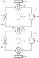
도 1은, 종래 기술에 따른 열 펌프 케스케이드 ― 본 경우에, 열 펌프 케스케이드는, 2개의 열 펌프 회로들을 구비한 열 펌프 배열체에 대응함 ― 의 개략도이고;
도 2는, 온도에 대하여 그려진, 열 펌프 배열체의 다양한 유체들의 용적 가열 용량들의 각각의 곡선들의 개략도이며; 그리고
도 3은, 2개의 열 펌프 회로들 ― 열 펌프 회로들 중 하나는, 유체로서 플루오로케톤을 이용하여 작동됨 ― 을 구비한 열 펌프 배열체에 대응하는 열 펌프 케스케이드의 개략도이다.Additional advantages, features, and details of the present invention will become apparent from the claims, by way of the following description of the preferred embodiments, and by reference to the drawings.
1 is a schematic view of a heat pump cascade according to the prior art, in which case the heat pump cascade corresponds to a heat pump arrangement with two heat pump circuits;
2 is a schematic view of the respective curves of the volume heating capacities of the various fluids of the heat pump arrangement drawn against temperature; And
Figure 3 is a schematic diagram of a heat pump cascade corresponding to a heat pump arrangement with two heat pump circuits-one of the heat pump circuits operating with fluoro ketone as fluid.
도 1은, 종래 기술에 따라, 케스케이드 열 펌프(1)로 알려지고, 2개의 열 펌프 회로들을 포함하는 열 펌프 배열체의 개략도이다. 케스케이드 열 펌프(1)는, 제 1 열 펌프(2) ― 제 1 유체가 제 1 열 펌프를 통해 유동함 ―, 및 제 2 열 펌프(3) ― 제 2 유체가 제 2 열 펌프를 통해 유동함 ― 를 포함한다. 제 1 및 제 2 유체들은, 열 교환기(19)에 의한 열 전달을 위해, 서로 커플링된다(coupled). 이러한 경우, 열 교환기(19)는 제 1 열 펌프(2)의 응축기(6) 및 제 2 열 펌프(3)의 증발기(8)를 포함한다. 제 1 열 펌프(2)의 제 1 유체는 증발기(4)에 의해 증발되고, 여기서 증발기(4)에는 열원(12)에 의해 열 에너지가 공급된다. 증발기(4)에 의해 가열된 제 1 유체는, 제 1 열 펌프(2)에 의해, 상기 제 1 열 펌프(2)의 압축기(5)에 의해서, 화살표(14)의 방향으로 전달된다. 그런 다음에, 응축기(6)의 가열되고 압축된 제 1 유체는 열을 증발기(8)에 방출하고, 여기서 제 2 열 펌프(3)의 제 2 유체는 증발기(8)에 의해 증발된다. 이러한 열의 방출에 후속하여, 제 1 유체는 제 1 열 펌프(2)의 팽창 밸브(expansion valve; 7)에 의해 팽창되고, 그 후에 다시 한번, 증발기(4)를 통해 열을 흡수한다. 따라서, 제 1 열 펌프(2)의 회로는 폐쇄형(closed)이다. 열 교환기(19)에 의해 가열된, 즉, 제 1 열 펌프(2)의 응축기(6)에 의한 제 2 열 펌프(3)의 증발기(8)로의 열의 방출에 의해 가열된, 제 2 열 펌프(3)의 제 2 유체는 제 2 열 펌프(3)의 압축기(9)에 의해 압축되고, 제 2 열 펌프(3)의 응축기(10)에서 열을 히트 싱크(13)에 방출한다. 그런 후에, 제 2 유체는 화살표(15)의 방향으로 제 2 열 펌프(3)의 팽창 밸브(11)를 통해 유동하고, 팽창 밸브에서 팽창된다. 그런 후에, 제 2 유체는 다시, 열 교환기(19)에 의해 열을 흡수하며, 따라서, 제 2 열 펌프(3)의 회로는 폐쇄형이다.1 is a schematic diagram of a heat pump arrangement, known in the prior art, known as a cascade heat pump 1, comprising two heat pump circuits. The cascade heat pump (1) is characterized in that the first heat pump (2) - the first fluid flows through the first heat pump and the second heat pump (3) - the second fluid flows through the second heat pump . The first and second fluids are coupled to each other for heat transfer by the heat exchanger (19). In this case, the
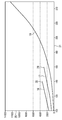
도 2는 용적 가열 용량들의 상이한 곡선들의 개략도이고, 여기서 도면의 y축은 용적 가열 용량(20)을 나타내고, x축은 유체의 응축 온도에 대응하는 유체 온도(21)를 나타낸다. 이러한 도면은, NOVEC 524로 알려진 플루오로케톤의 가열 용량 곡선에 대응하는 가열 용량 곡선(16)이, NOVEC 649로 알려진 플루오로케톤의 가열 용량 곡선에 대응하는 가열 용량 곡선(17)보다, 동일한 유체 온도들(21)에 대해서 각각의 경우에 더 높은 값들을 갖는 것을 도시한다. 도면으로부터 명백한 바와 같이, 가열 용량 곡선(16)도 가열 용량 곡선(17)도, 유체 온도(21)가 그려진 x축의 전체 길이에 걸쳐서 연장되지 않는다. 따라서, 플루오로케톤 NOVEC 524의 가열 용량 곡선(16)은 148℃의 임계점(28)에 도달함으로써 제한되고, 플루오로케톤 NOVEC 649의 가열 용량 곡선(17)은, 예를 들어, 169℃의 임계점(29)에 도달함으로써 제한된다. 그렇지만, 도면으로부터 명백한 바와 같이, 물의 가열 용량 곡선에 대응하는 가열 용량 곡선(18)은, 2개의 플루오로케톤들과 비교하여, 동일한 유체 온도들(21)에 대해서 각각의 경우에 가장 낮은 용적 가열 용량(20)을 가지며, 물의 임계점에 도달되는 것 없이, 특히 넓은 범위의 유체 온도들(21)에 걸쳐 물이 사용될 수 있다. 도 2로부터 부가적으로 명백한 바와 같이, 임계점(28) 및 임계점(29) 미만의 유체 온도들에서 물의 가열 용량 곡선(18)은, 각각, 가열 용량 곡선(16) 및 가열 용량 곡선(17) 아래에 있지만, 높은 유체 온도들(21)에서는, 물의 가열 용량 곡선(18)은, 각각의 임계점들(28 및 29)에 각각 도달된 결과로서 가열 용량 곡선(16) 및 가열 용량 곡선(17)에 의해 도달될 수 있는 것보다, 더 큰 값들로 상승한다. 게다가, 플루오로케톤 NOVEC 649가 제 1 열 펌프(2)의 제 1 유체로서 사용되는 경우, 작업 온도가 적어도 160℃인 다량의 열이, 케스케이드 열 펌프(1)에 의해, 히트 싱크(13)에 방출될 수 있다는 것이 명백하다. 최대 160℃의 온도에서, 이러한 제 1 유체로부터 제 2 유체로 열 교환기(19)에 의해 전달되는 열의 양에 기초하여, 제 2 열 펌프(3)의 제 2 유체가 추가적으로 가열되기 때문에, 심지어 160℃보다 더 높은 유용한 열의 온도가 제 2 열 펌프(3)에 의해 도달될 수 있다.2 is a schematic diagram of different curves of volumetric heating capacities, where the y axis of the figure represents the volumetric heating capacity 20 and the x axis represents the
제 1 유체로부터 제 2 유체로의 열 방출은 열 교환기(19)에 의해 등온적으로 진행되어야하기 때문에, 케스케이드 열 펌프(1)의 제 1 열 펌프(2)를 위한 유체를 위해, 오직 임계치 미만으로 작동되는 유체들만이 선택 사항들이다. 등온적인 열 방출을 허용하기 위해, 제 1 열 펌프(2)의 제 1 유체는, 각각의 임계점(28 또는 29)의 임계 온도 미만인 유체 온도(21)에서 작동된다. 열 펌프들(2, 3) 중 하나 의 열 펌프의 유체의 용적 가열 용량(20)이 더 높을수록, 각각의 열 펌프(2, 3)는 더 효율적으로 작동한다. 따라서, 각각의 더 높은 용적 가열 용량(20)에 의해, 등온적으로 달성 가능한 열 펌프의 성능 계수가 또한 증가한다.For the fluid for the
도 2 및 도 3을 함께 살펴볼 때 명백한 바와 같이, 예를 들어, NOVEC 524와 같은 플루오로케톤(26)이 제 1 열 펌프(2)의 제 1 유체로서 사용되는 것이 특히 유리하다. 이러한 관점에서, 열 교환기(19)에 의한 제 2 열 펌프(3)의 제 2 유체로의 등온적인 열 방출을 허용하기 위해, 유체 온도(21) ― 플루오로케톤(26)이 유체 온도(21)까지 가열됨 ― 가 임계점(28)의 기초(fundamental) 임계 온도 미만에서 머무른다는 것이 주지되어야 한다. 예를 들어, 제 2 열 펌프(3)의 제 2 유체로서, 물(27)이 사용된다.2 and 3, it is particularly advantageous, for example, that the
도 3의 개략도에 예시된 케스케이드 열 펌프(1)는 실질적으로, 도 1에서 이미 설명된 컴포넌트(component)들을 포함하고, 그러한 이유로, 오직 차이점들만 이하에서 설명될 것이다.The cascade heat pump 1 illustrated in the schematic of FIG. 3 includes substantially the components already described in FIG. 1, and for that reason only the differences will be described below.
도 3에 따른 열 교환기(19)는, 응축기(6) 및 증발기(8) 대신에, 제 1 열 펌프(2)의 고온 응축기(22) 및 제 2 열 펌프(3)의 고온 증발기(23)를 포함한다. 게다가, 도 3에서 볼 수 있는 바와 같이, 물(27)을 전달하는 데에, 압축기(9) 대신에 액체 링 압축기(24)가 사용된다. 액체 링 압축기(24)에 의해서, 고온 증발기에 의한 열의 입력의 결과로서 앞서서 증발된 물(27)이 이제 압축되어 고온 응축기(25)에 공급된다.The
플루오로케톤(26)의 3000kJ/㎥를 초과하는, 그리고 따라서 1500kJ/㎥를 현저하게 초과하는 특히 높은 용적 가열 용량에 기인하여, 임계점(28)의 임계 온도를 초과하지 않는, 플루오로케톤(26)의 140℃의 유체 온도(21)에서, 제 1 열 펌프(2)의 고온 응축기(22)에 의해 다량의 열이 제 2 열 펌프(3)의 고온 증발기(23)로 전달된다. 따라서, 특히 높은 온도에서 다량의 열이, 고온 증발기(23)에 의해 물(27)에 방출될 수 있고, 여기서, 결과로서, 특히 높은 온도에서 다량의 유용한 열이, 고온 응축기(25)에 의해, 히트 싱크(13)에 방출될 수 있다. 제 2 열 펌프(3)에서 유체로서 운반되는 물(27)이, 열 교환기(19)에 의해 플루오로케톤(26)으로부터 물(27)로 전달되는 140℃의 열의 양에 의해, 예를 들어, 200℃의 온도까지 가열되는 경우, 이는, 물(27)의 60℃의 온도의 상승에 대응한다. 200℃에서, 물(27)의 용적 발열량(20)은 합계가 4000kJ/㎥, 즉, 1500kJ/㎥보다 현저하게 더 높은 값을 초과한다.Does not exceed the critical temperature of the
Claims (10)
상기 열 펌프 배열체에서, 제 1 유체(26)가 제 1 열 펌프(2)를 통해 유동하고 제 2 유체(27)가 제 2 열 펌프(3)를 통해 유동하며, 열 교환기(19)를 사용하여 상기 제 1 유체(26)로부터 상기 제 2 유체(27)로 열이 전달되고,
유용한 열이, 적어도 120℃의 유체 온도(21)에서 상기 제 2 유체(27)로부터 추출되고, 상기 제 2 유체(27)의 유용한 열은, 적어도 500kJ/㎥의 상기 제 2 유체(27)의 그리고 상기 제 1 유체(26)의 용적 가열 용량(20)으로 방출되는 것을 특징으로 하는,
열 펌프 배열체를 작동시키기 위한 방법.
1. A method for operating a heat pump arrangement (1)
In the heat pump arrangement, a first fluid 26 flows through the first heat pump 2, a second fluid 27 flows through the second heat pump 3, and the heat exchanger 19 Heat is transferred from the first fluid 26 to the second fluid 27,
Useful heat is extracted from the second fluid 27 at a fluid temperature 21 of at least 120 ° C and the useful heat of the second fluid 27 is such that the heat of the second fluid 27 of at least 500 kJ / And is discharged into the volumetric heating capacity (20) of the first fluid (26).
A method for operating a heat pump arrangement.
상기 유용한 열은, 바람직하게, 적어도 150℃ 그리고, 특히 바람직하게는, 적어도 160℃의 유체 온도(21)에서 상기 제 2 유체(27)로부터 추출되는 것을 특징으로 하는,
열 펌프 배열체를 작동시키기 위한 방법.
The method according to claim 1,
Characterized in that said useful heat is extracted from said second fluid (27) at a fluid temperature (21), preferably at least 150 ° C and very particularly preferably at least 160 ° C.
A method for operating a heat pump arrangement.
적어도 하나의 플루오로케톤(fluoroketone)이, 상기 제 1 유체(26)로서, 상기 제 1 열 펌프(2)를 통해 유동하는 것을 특징으로 하는,
열 펌프 배열체를 작동시키기 위한 방법.
3. The method according to claim 1 or 2,
Characterized in that at least one fluoroketone flows through said first heat pump (2) as said first fluid (26).
A method for operating a heat pump arrangement.
물 또는 적어도 하나의 플루오로케톤이 상기 제 2 유체(27)로서 사용되는 것을 특징으로 하는,
열 펌프 배열체를 작동시키기 위한 방법.
4. The method according to any one of claims 1 to 3,
Characterized in that water or at least one fluoroketone is used as said second fluid (27)
A method for operating a heat pump arrangement.
상이한 유체들이 상기 제 1 유체(26) 및 상기 제 2 유체(27)로서 사용되는 것을 특징으로 하는,
열 펌프 배열체를 작동시키기 위한 방법.
5. The method according to any one of claims 1 to 4,
Characterized in that different fluids are used as the first fluid (26) and the second fluid (27)
A method for operating a heat pump arrangement.
상기 제 1 유체(26)로부터 상기 제 2 유체(27)로의 열 방출은 대체로 등온적으로(isothermally) 진행되는 것을 특징으로 하는,
열 펌프 배열체를 작동시키기 위한 방법.
6. The method according to any one of claims 1 to 5,
Characterized in that heat dissipation from the first fluid (26) to the second fluid (27) proceeds substantially isothermally.
A method for operating a heat pump arrangement.
상기 제 2 유체(27)의 유용한 열은, 적어도 1000kJ/㎥, 바람직하게는, 적어도 1200kJ/㎥, 그리고 특히 바람직하게는, 적어도 1500kJ/㎥의 제 2 유체(27) 및 제 1 유체(26)의 용적 가열 용량(20)으로 방출되는 것을 특징으로 하는,
열 펌프 배열체를 작동시키기 위한 방법.
7. The method according to any one of claims 1 to 6,
The useful heat of the second fluid 27 is the heat of the second fluid 27 and the first fluid 26 of at least 1000 kJ / m 3, preferably at least 1200 kJ / m 3 and particularly preferably at least 1500 kJ / Is discharged to a volume heating capacity (20)
A method for operating a heat pump arrangement.
적어도 하나의 제 1 열 펌프(2) ― 제 1 유체(26)는 상기 제 1 열 펌프(2)를 통해 유동함 ―, 및 제 2 열 펌프(3) ― 제 2 유체(27)는 상기 제 2 열 펌프(3)를 통해 유동함 ― 를 가지며, 열 교환기(19)를 사용하여 상기 제 1 유체(26)로부터 상기 제 2 유체(27)로 열이 전달될 수 있고,
유용한 열은, 적어도 120℃의 유체 온도(21)에서 상기 제 2 유체(27)를 사용하여 전달될 수 있으며, 상기 제 1 유체(26) 및 상기 제 2 유체(27)는 적어도 500kJ/㎥의 용적 가열 용량(volumetric heating capacity; 20)을 갖는 것을 특징으로 하는,
열 펌프 배열체.
As a heat pump arrangement (1)
At least one first heat pump (2) - a first fluid (26) flows through the first heat pump (2) and a second heat pump (3) - a second fluid (27) Heat pump 3 and heat can be transferred from the first fluid 26 to the second fluid 27 using a heat exchanger 19,
Useful heat may be transferred using the second fluid 27 at a fluid temperature 21 of at least 120 ° C and the first fluid 26 and the second fluid 27 may be delivered at a rate of at least 500 kJ / Characterized in that it has a volumetric heating capacity (20)
Heat pump arrangement.
상기 제 1 유체(26) 및/또는 상기 제 2 유체(27)의 적어도 하나의 온도 상승은 적어도 2단계 압축에 의해 증가될 수 있는 것을 특징으로 하는,
열 펌프 배열체.
9. The method of claim 8,
Characterized in that the temperature rise of at least one of the first fluid (26) and / or the second fluid (27) can be increased by at least two-
Heat pump arrangement.
상기 제 2 유체(27)는 액체 링(ring) 압축기(24)를 사용하여 대체로 등온적으로 압축 가능한 것을 특징으로 하는,
열 펌프 배열체.
10. The method according to claim 8 or 9,
Characterized in that said second fluid (27) is substantially isothermally compressible using a liquid ring compressor (24).
Heat pump arrangement.
Applications Claiming Priority (3)
| Application Number | Priority Date | Filing Date | Title |
|---|---|---|---|
| DE102013211087.1 | 2013-06-14 | ||
| DE102013211087.1A DE102013211087A1 (en) | 2013-06-14 | 2013-06-14 | Method for operating a heat pump assembly and heat pump assembly |
| PCT/EP2014/061528 WO2014198593A1 (en) | 2013-06-14 | 2014-06-04 | Method for operating a heat pump arrangement, and heat pump arrangement |
Related Child Applications (1)
| Application Number | Title | Priority Date | Filing Date |
|---|---|---|---|
| KR1020187000078A Division KR20180005281A (en) | 2013-06-14 | 2014-06-04 | Method for operating a heat pump arrangement, and heat pump arrangement |
Publications (1)
| Publication Number | Publication Date |
|---|---|
| KR20160018795A true KR20160018795A (en) | 2016-02-17 |
Family
ID=50897593
Family Applications (2)
| Application Number | Title | Priority Date | Filing Date |
|---|---|---|---|
| KR1020167000674A KR20160018795A (en) | 2013-06-14 | 2014-06-04 | Method for operating a heat pump arrangement, and heat pump arrangement |
| KR1020187000078A KR20180005281A (en) | 2013-06-14 | 2014-06-04 | Method for operating a heat pump arrangement, and heat pump arrangement |
Family Applications After (1)
| Application Number | Title | Priority Date | Filing Date |
|---|---|---|---|
| KR1020187000078A KR20180005281A (en) | 2013-06-14 | 2014-06-04 | Method for operating a heat pump arrangement, and heat pump arrangement |
Country Status (8)
| Country | Link |
|---|---|
| US (1) | US20160138837A1 (en) |
| EP (1) | EP2989395A1 (en) |
| JP (1) | JP6526639B2 (en) |
| KR (2) | KR20160018795A (en) |
| CN (1) | CN105264306A (en) |
| CA (1) | CA2915305C (en) |
| DE (1) | DE102013211087A1 (en) |
| WO (1) | WO2014198593A1 (en) |
Families Citing this family (8)
| Publication number | Priority date | Publication date | Assignee | Title |
|---|---|---|---|---|
| DE102013214891A1 (en) * | 2013-07-30 | 2015-02-05 | Siemens Aktiengesellschaft | Thermal engineering interconnection of a geothermal energy source with a district heating network |
| EP3158130B1 (en) * | 2014-07-29 | 2018-03-28 | Siemens Aktiengesellschaft | Method and apparatus for drying stock and industrial plant |
| DE112015004688T5 (en) * | 2014-10-18 | 2018-01-18 | Aerosol Dynamics Inc. | Persistent supersaturations for condensation growth of particles |
| KR102096201B1 (en) | 2016-02-26 | 2020-04-01 | 시노켐 란티안 컴퍼니 리미티드 | Composition comprising a fluorine-containing ketone |
| DE102016204158A1 (en) * | 2016-03-14 | 2017-09-14 | Efficient Energy Gmbh | Heat pump system with two stages, method for operating a heat pump system and method for producing a heat pump system |
| DE102017011134B4 (en) | 2017-12-01 | 2022-09-08 | Emz-Hanauer Gmbh & Co. Kgaa | Household refrigeration appliance and method for controlling a light source arrangement arranged in this appliance |
| EP4063762A1 (en) | 2021-03-26 | 2022-09-28 | Mitsubishi Electric R&D Centre Europe B.V. | Cascaded heat pump system with low gwp refrigerant |
| AU2022291952A1 (en) * | 2021-06-16 | 2024-01-04 | Atmoszero, Inc. | Air source heat pump system and method of use for industrial steam generation |
Family Cites Families (25)
| Publication number | Priority date | Publication date | Assignee | Title |
|---|---|---|---|---|
| SE394741B (en) * | 1974-04-18 | 1977-07-04 | Projectus Ind Produkter Ab | VERMEPUMPSYSTEM |
| FR2374539A1 (en) * | 1976-12-15 | 1978-07-13 | Air Ind | WATER VAPOR COMPRESSION PROCESS, AND THERMAL CIRCUITS FOR ITS IMPLEMENTATION |
| US4149389A (en) * | 1978-03-06 | 1979-04-17 | The Trane Company | Heat pump system selectively operable in a cascade mode and method of operation |
| DE3433366A1 (en) * | 1984-09-08 | 1986-03-20 | Peter 2351 Hasenkrug Koch | Process for the supply and discharge of heat energy, and also heat pump device |
| JPS61138059A (en) * | 1984-12-10 | 1986-06-25 | 三井造船株式会社 | Heat pump for high temperature |
| JPS62190360A (en) * | 1986-02-17 | 1987-08-20 | 株式会社東芝 | Cascade coupled heat pump device |
| US4907410A (en) * | 1987-12-14 | 1990-03-13 | Chang Yan P | Thermal energy from environmental fluids |
| US5241829A (en) * | 1989-11-02 | 1993-09-07 | Osaka Prefecture Government | Method of operating heat pump |
| US7100380B2 (en) * | 2004-02-03 | 2006-09-05 | United Technologies Corporation | Organic rankine cycle fluid |
| KR20070053265A (en) * | 2004-09-17 | 2007-05-23 | 바스프 악티엔게젤샤프트 | Method for operating a liquid ring compressor |
| EP1764487A1 (en) * | 2005-09-19 | 2007-03-21 | Solvay Fluor GmbH | Working fluid for a OCR-process |
| JP5612250B2 (en) * | 2008-03-07 | 2014-10-22 | 出光興産株式会社 | Lubricating oil composition for refrigerator |
| PL2247562T3 (en) * | 2008-03-07 | 2018-03-30 | Arkema, Inc. | Use of r-1233 in liquid chillers |
| US20130091843A1 (en) * | 2008-12-05 | 2013-04-18 | Honeywell International Inc. | Fluoro olefin compounds useful as organic rankine cycle working fluids |
| US8871112B2 (en) * | 2008-11-19 | 2014-10-28 | E I Du Pont De Nemours And Company | Compositions comprising 2,3,3,3-tetrafluoropropene and hydrocarbons and uses thereof |
| FR2941039B1 (en) * | 2009-01-14 | 2013-02-08 | Arkema France | HEAT TRANSFER METHOD |
| IT1396440B1 (en) * | 2009-10-14 | 2012-11-23 | Innovation Factory Scarl | THERMODYNAMIC IRREVERSIBLE CYCLE HEATING DEVICE FOR HEATING SYSTEMS WITH HIGH DELIVERY TEMPERATURE. |
| JP2013510286A (en) * | 2009-11-03 | 2013-03-21 | イー・アイ・デュポン・ドウ・ヌムール・アンド・カンパニー | Cascade refrigeration system using fluoroolefin refrigerant |
| DE202009016576U1 (en) * | 2009-12-08 | 2011-01-13 | Gebhardt, Peter | Apparatus for heat recovery comprising two heat pumps |
| US8846754B2 (en) * | 2009-12-16 | 2014-09-30 | Honeywell International Inc. | Azeotrope-like compositions of cis-1,1,1,4,4,4-hexafluoro-2-butene |
| DE102010001929B4 (en) * | 2010-02-15 | 2014-06-18 | Konvekta Ag | Refrigeration system for cooling an enclosed space |
| US8535559B2 (en) * | 2010-03-26 | 2013-09-17 | 3M Innovative Properties Company | Nitrogen-containing fluoroketones for high temperature heat transfer |
| JP2012172866A (en) * | 2011-02-18 | 2012-09-10 | Showa Denko Kk | Ebullient cooling apparatus |
| DE102011086476A1 (en) * | 2011-09-30 | 2013-04-04 | Siemens Aktiengesellschaft | High temperature heat pump and method of using a working medium in a high temperature heat pump |
| US10385247B2 (en) * | 2014-09-23 | 2019-08-20 | The Chemours Company Fc, Llc | Use of (2E)-1,1,1,4,5,5,5-heptafluoro-4-(trifluoromethyl)pent-2-ene in high temperature heat pumps |
-
2013
- 2013-06-14 DE DE102013211087.1A patent/DE102013211087A1/en not_active Withdrawn
-
2014
- 2014-06-04 JP JP2016518920A patent/JP6526639B2/en active Active
- 2014-06-04 CN CN201480032455.XA patent/CN105264306A/en active Pending
- 2014-06-04 KR KR1020167000674A patent/KR20160018795A/en active Application Filing
- 2014-06-04 EP EP14728920.1A patent/EP2989395A1/en not_active Withdrawn
- 2014-06-04 CA CA2915305A patent/CA2915305C/en active Active
- 2014-06-04 US US14/897,914 patent/US20160138837A1/en not_active Abandoned
- 2014-06-04 KR KR1020187000078A patent/KR20180005281A/en not_active Application Discontinuation
- 2014-06-04 WO PCT/EP2014/061528 patent/WO2014198593A1/en active Application Filing
Also Published As
| Publication number | Publication date |
|---|---|
| CN105264306A (en) | 2016-01-20 |
| JP6526639B2 (en) | 2019-06-05 |
| DE102013211087A1 (en) | 2015-01-15 |
| CA2915305A1 (en) | 2014-12-18 |
| EP2989395A1 (en) | 2016-03-02 |
| US20160138837A1 (en) | 2016-05-19 |
| CA2915305C (en) | 2018-04-10 |
| KR20180005281A (en) | 2018-01-15 |
| JP2016526650A (en) | 2016-09-05 |
| WO2014198593A1 (en) | 2014-12-18 |
Similar Documents
| Publication | Publication Date | Title |
|---|---|---|
| KR20160018795A (en) | Method for operating a heat pump arrangement, and heat pump arrangement | |
| US10024198B2 (en) | Heat engine system including an integrated cooling circuit | |
| Kondou et al. | Thermodynamic assessment of high-temperature heat pumps using Low-GWP HFO refrigerants for heat recovery | |
| Dahmani et al. | Optimum design of ejector refrigeration systems with environmentally benign fluids | |
| EP2157317B1 (en) | Thermoelectric energy storage system and method for storing thermoelectric energy | |
| JP2016526650A5 (en) | ||
| Hu et al. | Exergy analysis of R1234ze (Z) as high temperature heat pump working fluid with multi-stage compression | |
| JP2014528053A (en) | High temperature heat pump and method of using working medium in high temperature heat pump | |
| CN105899889B (en) | Refrigerating plant | |
| Arora et al. | Energy and exergy analysis of a combined transcritical CO2 compression refrigeration and single effect H2O-LiBr vapour absorption system | |
| ITPD20090298A1 (en) | THERMODYNAMIC IRREVERSIBLE CYCLE HEATING DEVICE FOR HEATING SYSTEMS WITH HIGH DELIVERY TEMPERATURE | |
| CN107407510A (en) | Use the Absorption Cooling System of LGWP refrigerants | |
| Dubey et al. | Performance evaluation and optimal configuration analysis of a transcritical carbon dioxide/propylene cascade system with vortex tube expander in high-temperature cycle | |
| Soni et al. | Exergy analysis of vapour compression refrigeration system with using R-407C and R-410A | |
| YILMAZ et al. | Energy and exergy analyses of CO2/HFE7000 cascade cooling system | |
| CN105745401B (en) | Recuperation of heat and method for improving and the compressor for the method | |
| Maurya et al. | Combined refrigeration cycle for thermal power plant using low grade waste steam | |
| RU2614133C1 (en) | Throttle-free heat pump unit | |
| JP2020106178A (en) | Heat recovery system and heat recovery method | |
| CN103982253A (en) | Single-stage gravity pump organic Rankine power generation and heat supply combined system and cycle thereof | |
| TWI427252B (en) | Cooling system for waste heat recycle | |
| Kılıç et al. | Evaluating on exergy analysis of refrigeration system with two-stage and economiser | |
| CN106766354B (en) | Mechanical flash evaporation type heat pump air conditioning system and working method thereof | |
| CN111365895A (en) | Efficient and environment-friendly waste heat recovery system and heat transfer method | |
| Rusowicz et al. | Influence of the temperature difference between the heat source and the evaporation temperature in ORC systems working with natural refrigerants |
Legal Events
| Date | Code | Title | Description |
|---|---|---|---|
| A201 | Request for examination | ||
| E902 | Notification of reason for refusal | ||
| AMND | Amendment | ||
| E902 | Notification of reason for refusal | ||
| AMND | Amendment | ||
| E601 | Decision to refuse application | ||
| E601 | Decision to refuse application | ||
| E801 | Decision on dismissal of amendment | ||
| A107 | Divisional application of patent | ||
| J201 | Request for trial against refusal decision | ||
| J301 | Trial decision |
Free format text: TRIAL NUMBER: 2018101000016; TRIAL DECISION FOR APPEAL AGAINST DECISION TO DECLINE REFUSAL REQUESTED 20180102 Effective date: 20190902 |