KR20160014506A - Printhead control - Google Patents
Printhead control Download PDFInfo
- Publication number
- KR20160014506A KR20160014506A KR1020147034711A KR20147034711A KR20160014506A KR 20160014506 A KR20160014506 A KR 20160014506A KR 1020147034711 A KR1020147034711 A KR 1020147034711A KR 20147034711 A KR20147034711 A KR 20147034711A KR 20160014506 A KR20160014506 A KR 20160014506A
- Authority
- KR
- South Korea
- Prior art keywords
- printhead
- pixel
- printheads
- overlapping
- Prior art date
Links
Images


Classifications
-
- B—PERFORMING OPERATIONS; TRANSPORTING
- B41—PRINTING; LINING MACHINES; TYPEWRITERS; STAMPS
- B41J—TYPEWRITERS; SELECTIVE PRINTING MECHANISMS, i.e. MECHANISMS PRINTING OTHERWISE THAN FROM A FORME; CORRECTION OF TYPOGRAPHICAL ERRORS
- B41J2/00—Typewriters or selective printing mechanisms characterised by the printing or marking process for which they are designed
- B41J2/005—Typewriters or selective printing mechanisms characterised by the printing or marking process for which they are designed characterised by bringing liquid or particles selectively into contact with a printing material
- B41J2/01—Ink jet
- B41J2/015—Ink jet characterised by the jet generation process
- B41J2/04—Ink jet characterised by the jet generation process generating single droplets or particles on demand
- B41J2/045—Ink jet characterised by the jet generation process generating single droplets or particles on demand by pressure, e.g. electromechanical transducers
- B41J2/04501—Control methods or devices therefor, e.g. driver circuits, control circuits
- B41J2/04541—Specific driving circuit
-
- B—PERFORMING OPERATIONS; TRANSPORTING
- B41—PRINTING; LINING MACHINES; TYPEWRITERS; STAMPS
- B41J—TYPEWRITERS; SELECTIVE PRINTING MECHANISMS, i.e. MECHANISMS PRINTING OTHERWISE THAN FROM A FORME; CORRECTION OF TYPOGRAPHICAL ERRORS
- B41J2/00—Typewriters or selective printing mechanisms characterised by the printing or marking process for which they are designed
- B41J2/005—Typewriters or selective printing mechanisms characterised by the printing or marking process for which they are designed characterised by bringing liquid or particles selectively into contact with a printing material
- B41J2/01—Ink jet
- B41J2/015—Ink jet characterised by the jet generation process
- B41J2/04—Ink jet characterised by the jet generation process generating single droplets or particles on demand
- B41J2/045—Ink jet characterised by the jet generation process generating single droplets or particles on demand by pressure, e.g. electromechanical transducers
- B41J2/04501—Control methods or devices therefor, e.g. driver circuits, control circuits
- B41J2/04593—Dot-size modulation by changing the size of the drop
-
- B—PERFORMING OPERATIONS; TRANSPORTING
- B41—PRINTING; LINING MACHINES; TYPEWRITERS; STAMPS
- B41J—TYPEWRITERS; SELECTIVE PRINTING MECHANISMS, i.e. MECHANISMS PRINTING OTHERWISE THAN FROM A FORME; CORRECTION OF TYPOGRAPHICAL ERRORS
- B41J2/00—Typewriters or selective printing mechanisms characterised by the printing or marking process for which they are designed
- B41J2/005—Typewriters or selective printing mechanisms characterised by the printing or marking process for which they are designed characterised by bringing liquid or particles selectively into contact with a printing material
- B41J2/01—Ink jet
- B41J2/015—Ink jet characterised by the jet generation process
- B41J2/04—Ink jet characterised by the jet generation process generating single droplets or particles on demand
- B41J2/06—Ink jet characterised by the jet generation process generating single droplets or particles on demand by electric or magnetic field
-
- B—PERFORMING OPERATIONS; TRANSPORTING
- B41—PRINTING; LINING MACHINES; TYPEWRITERS; STAMPS
- B41J—TYPEWRITERS; SELECTIVE PRINTING MECHANISMS, i.e. MECHANISMS PRINTING OTHERWISE THAN FROM A FORME; CORRECTION OF TYPOGRAPHICAL ERRORS
- B41J2/00—Typewriters or selective printing mechanisms characterised by the printing or marking process for which they are designed
- B41J2/005—Typewriters or selective printing mechanisms characterised by the printing or marking process for which they are designed characterised by bringing liquid or particles selectively into contact with a printing material
- B41J2/01—Ink jet
- B41J2/135—Nozzles
- B41J2/145—Arrangement thereof
- B41J2/15—Arrangement thereof for serial printing
-
- B—PERFORMING OPERATIONS; TRANSPORTING
- B41—PRINTING; LINING MACHINES; TYPEWRITERS; STAMPS
- B41J—TYPEWRITERS; SELECTIVE PRINTING MECHANISMS, i.e. MECHANISMS PRINTING OTHERWISE THAN FROM A FORME; CORRECTION OF TYPOGRAPHICAL ERRORS
- B41J2/00—Typewriters or selective printing mechanisms characterised by the printing or marking process for which they are designed
- B41J2/005—Typewriters or selective printing mechanisms characterised by the printing or marking process for which they are designed characterised by bringing liquid or particles selectively into contact with a printing material
- B41J2/01—Ink jet
- B41J2/135—Nozzles
- B41J2/145—Arrangement thereof
- B41J2/155—Arrangement thereof for line printing
-
- B—PERFORMING OPERATIONS; TRANSPORTING
- B41—PRINTING; LINING MACHINES; TYPEWRITERS; STAMPS
- B41J—TYPEWRITERS; SELECTIVE PRINTING MECHANISMS, i.e. MECHANISMS PRINTING OTHERWISE THAN FROM A FORME; CORRECTION OF TYPOGRAPHICAL ERRORS
- B41J2202/00—Embodiments of or processes related to ink-jet or thermal heads
- B41J2202/01—Embodiments of or processes related to ink-jet heads
- B41J2202/20—Modules
Abstract
프린팅을 위한 행 당 다수의 픽셀을 갖는 2차원의 비트맵 이미지를 프린팅하는 방법이 개시된다. 상기 방법 및 장치는 복수의 중첩된 프린트 헤드들(300) 또는 하나의 프린트 헤드 또는 중첩 위치를 따라 인덱싱된 복수의 프린트들 중 하나를 사용한다. 상기 또는 각각의 프린트 헤드는 분사 채널(301)의 행을 구비하고, 이의 각각은 프린팅 유체의 본체 내로부터 형성된 미립자 응집체를 야기하기 위해 전압이 인가되는 관련 분사 전극을 구비한다. 상기 중첩되는 프린트 헤드 중 선택된 분사 채널로부터 프린트된 액적으로서 분사되는 대전된 미립자 응집체의 부피가 소정의 다수의 부피 크기 중 하나로 형성되도록 하기 위하여, 각각의 이미지 픽셀 비트 값에 의해 결정되는 각각의 소정의 진폭(amplitude) 및 길이(duration)를 갖는 전압 펄스(VE)가 상기 선택된 분사 채널에 인가된다. 상기 이미지의 각 행에 있어서, 중첩되는 분사 채널에 의해 프린트된 픽셀을 형성하기 위해 상기 중첩된 프린트 헤드에 인가되는 전압 펄스(VE)의 값은, 상기 프린트 헤드의 중첩되는 영역 내의 상기 픽셀의 위치 및 상기 픽셀의 소정의 부피 크기에 의존한다.A method for printing a two-dimensional bitmap image having a plurality of pixels per row for printing is disclosed. The method and apparatus use a plurality of overlapping printheads 300 or one of a plurality of prints indexed along a printhead or overlap position. The or each printhead has a row of ejection channels 301, each of which has an associated ejection electrode to which a voltage is applied to cause particulate aggregates formed from within the body of the printing fluid. In order to ensure that the volume of charged particulate agglomerates ejected as printed droplets from a selected one of the overlapping print heads is formed into one of a plurality of predetermined volume sizes, A voltage pulse (V E ) having an amplitude and a duration is applied to the selected injection channel. For each row of the image, the value of the voltage pulse (V E ) applied to the superimposed print head to form a pixel printed by the overlapping jetting channels is determined by the value of the voltage pulse Position and the predetermined volume size of the pixel.
Description
본 발명은 정전 잉크젯 프린트 기술에 관한 것이고, 더 구체적으로는 WO 90/11866 및 관련 특허 명세서에서 설명된 바와 같은 타입의 프린트 헤드 및 프린터에 관한 것이다.
The present invention relates to electrostatic ink jet printing techniques, and more particularly to printheads and printers of the type described in WO 90/11866 and related patents.
이러한 타입의 정전 프린터들은 인가된 전기장을 이용하여 고체 입자들을 먼저 농축하고 이어서 분사함으로써 화학적으로 비활성인 절연성 반송 유체에 분산되는 대전된 고체 입자들을 분사한다. 농축은, 인가된 전기장이 전기영동을 야기하고 대전된 입자들이 잉크의 표면과 조우할 때까지 전기장에서 기판을 향해 이동하기 때문에 발생한다. 분사는, 인가된 전기장이, 표면 장력을 극복할 정도로 충분히 큰 전기영동 힘을 생성할 때 발생한다. 전기장은 분사 위치와 기판 사이에 전위차를 생성함으로써 생성되며; 이것은 전압들을 분사 위치의 그리고/또는 분사 위치 주변의 전극들에 인가함으로써 성취된다. 이러한 유형의 프린트 기술의 이점 중 통상적인 드롭-온-디맨드(DOD, drop-on-demand) 프린터를 넘어서는 특정 이점은 통상적인 DOD 프린터로는 불가능한 그레이스케일(grayscale)을 사용한 프린트가 가능하단 것이다.
These types of electrostatic printers use charged electric fields to first concentrate the solid particles and then to inject the charged solid particles dispersed in a chemically inactive insulating carrier fluid. Concentration occurs because the applied electric field causes electrophoresis and moves toward the substrate in the electric field until the charged particles encounter the surface of the ink. The injection occurs when the applied electric field creates an electrophoretic force large enough to overcome the surface tension. The electric field is created by creating a potential difference between the injection position and the substrate; This is accomplished by applying voltages to the electrodes at the injection position and / or around the injection position. One of the advantages of this type of printing technology over traditional drop-on-demand (DOD) printers is the ability to print using grayscale, which is not possible with conventional DOD printers.
분사가 발생하는 위치는 프린트 헤드 기하학적 구조와, 전기장을 생성하는 전극들의 위치 및 형상에 의해 결정된다. 전형적으로, 프린트 헤드는 프린트 헤드의 몸체로부터의 하나 이상의 돌출부들로 구성되며, 이들 돌출부들(분사 업스탠드들이라고도 알려져 있음)은 그들의 표면 상에 전극들을 갖는다. 전극들에 인가되는 바이어스의 극성은 대전된 입자의 극성과 동일하여, 전기영동 힘의 방향이 기판을 향하게 한다. 또한, 프린트 헤드 구조의 전체 기하학적 구조 및 전극들의 위치는, 농축 및 그 후의 분사가 돌출부들의 선단 주위의 고도로 국소화된 영역에서 발생하도록 설계된다.
The position at which the jetting occurs is determined by the geometry of the printhead and the position and shape of the electrodes generating the electric field. Typically, the printhead consists of one or more protrusions from the body of the printhead, and these protrusions (also known as ejection-up stands) have electrodes on their surface. The polarity of the bias applied to the electrodes is the same as the polarity of the charged particles, so that the direction of the electrophoretic force is directed toward the substrate. In addition, the overall geometry of the printhead structure and the position of the electrodes are designed such that concentration and subsequent ejection occurs in highly localized regions around the tips of the protrusions.
신뢰성 있게 동작하기 위해서는, 잉크가 계속해서 분사 위치를 통과하여 분사된 입자들을 보충하도록 해야 한다. 이러한 흐름을 가능하게 하기 위해, 잉크는 낮은 점성, 일반적으로는 수 센티푸아즈(centipoise)이어야 한다. 분사되는 물질은 고농축 입자들 때문에 고도로 점성이며; 그 결과, 비흡수성 기판들 상으로 프린트하도록 하는 기술이 이용될 수 있는데, 이는 그 물질이 충격에 확산되지 않을 것이기 때문이다.
In order to operate reliably, the ink must continue to pass through the injection position to replenish the injected particles. To enable this flow, the ink should be of low viscosity, generally centipoise. The material being sprayed is highly viscous due to the high concentration of particles; As a result, techniques for printing onto non-absorbent substrates can be used because the material will not diffuse into the impact.
WO 93/11866, WO 97/27058, WO 97/27056, WO 98/32609, WO 98/42515, WO 01/30576 및 WO 03/101741에서의 것들과 같은 다양한 프린트 헤드 설계들이 종래기술에서 설명되어 있고, 이 모두는 WO 93/11866에 기재된 소위 Tonejet® 방법에 관한 것이다.
Various printhead designs such as those in WO 93/11866, WO 97/27058, WO 97/27056, WO 98/32609, WO 98/42515, WO 01/30576 and WO 03/101741 have been described in the prior art , All of which are related to the so-called Tonejet® method described in WO 93/11866.
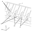
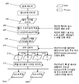
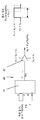
도 1은 종래기술에서 설명된 타입의 정전 프린트 헤드(1)의 선단 영역의 도면이며, 각각이 선단(21)을 구비한 다수의 분사 업스탠드들(2)을 도시한다. 각각의 2개의 분사 업스탠드들 사이에는, 각각의 분사 셀(5) 또는 분사기의 경계를 정의하는 벽(3)(치크(cheek)라고도 지칭됨)이 있다. 각각의 셀에서는, 분사 업스탠드(2)의 각각의 측면 상에 하나씩 있는 2 개의 채널들(4)에서 잉크가 흐르고, 사용 시, 잉크 메니스커스(meniscus)가 치크들의 상측과 분사 업스탠드의 상측 사이에 고정(pin)된다. 이 기하학적 구조에서, z 축의 포지티브 방향은 기판으로부터 프린트 헤드를 가리키는 것으로서 정의되고, x 축은 분사 업스탠드들의 선단들의 라인들을 따르는 것을 가리키며, y 축은 이들에 직교한다.
Fig. 1 is a diagram of the leading edge area of an
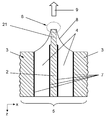
도 2는 동일한 프린트 헤드(1)에서 단일 분사 셀(5)의 x-z 평면의 개략도이며, y 축을 따라서 보이는, 업스탠드들(2)의 선단들의 중간을 관통한 단면을 취한다. 이 도면은 치크들(3), 분사 업스탠드(2), 분사 위치(6), 분사 전극들(7)의 위치, 및 잉크 메니스커스(8)의 위치를 도시한다. 실선 화살표(9)는 분사 방향을 나타내고, 또한 기판을 가리킨다. 각 업스탠드(2) 및 이와 관련한 전극들 및 잉크 경로는 효과적으로 분사 채널을 형성한다. 일반적으로, 분사 셀들(168) 사이의 피치는 168 ㎛이다. 도 2에 도시된 예에서, 잉크는, 보통, 독자로부터 떠나 페이지 내로 유동한다.
Fig. 2 is a schematic view of the xz plane of a
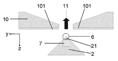
도 3은 x 축을 따라서 분사 업스탠드의 측면도를 도시한 y-z 평면에서의 동일한 프린트 헤드(1)의 개략도이다. 이 도면은 분사 업스탠드(2), 업스탠드 상에서의 전극(7)의 위치, 및 중간 전극(10)으로서 알려진 콤포넌트를 도시한다. 중간 전극(10)은, 사용 시, 분사 업스탠드들(2) 상의 분사 전극들(7)의 것으로부터 차분 전위로 바이어스되는 전극들(101)을 그의 내부면 (그리고, 때때로, 그의 전체 표면) 상에 갖는 구조이다. 중간 전극(10)은, 각각의 분사 업스탠드(2)가, 그것에 면하고 있고 개별적으로 어드레싱될 수 있는 전극을 갖도록 패턴화될 수도 있고, 또는 그것은 중간 전극(10)의 전체 표면이 일정한 바이어스에서 유지되도록 균일하게 금속화될 수 있다. 중간 전극(10)은 외부 전기장들로부터 분사 위치/분사기를 보호함으로써 정전 실드(electrostatic shield)로서 작용하고, 분사 위치(6)에서의 전기장이 주의 깊게 제어되도록 한다.
Figure 3 is a schematic view of the
실선 화살표(11)는 분사 방향을 나타내고, 또한 기판의 방향을 가리킨다. 도 3에서, 잉크는 대체로 좌측으로부터 우측으로 흐른다.
The
동작 시, 기판을 접지(0 V)로 유지하고 중간 전극(10)과 기판 사이에 전압 VIE를 인가하는 것이 일반적이다. VB의 추가 전위차는 분사 업스탠드(2) 및 치크들(3) 상에서 중간 전극(10)과 전극들(7) 사이에 인가되어, 이들 전극들의 전위가 VIE + VB 이 되게 한다. VB의 크기는 입자들을 농축하지만 입자들을 분사하지 않는 분사 위치(6)에 전기장이 생성되도록 선택된다. 분사는 입자들 상에서의 전기영동 힘이 잉크의 표면 장력과 정확하게 균형을 이루는 전기장 세기에 대응하는 소정 임계 전압 VS보다 큰 인가된 바이어스 VB에서 자발적으로 발생한다. 따라서, 항상 그것은 VB가 VS보다 작도록 선택되는 경우이다. VB의 인가 시, 잉크 메니스커스(ink meniscus)는 분사 업스탠드(2)의 대부분을 커버하도록 전방으로 이동한다. 농축된 입자들을 분사하기 위해, 진폭 VP의 추가 전압 펄스는 분사 업스탠드(2)와 중간 전극(10) 사이의 전위차가 VB +VP가 되도록 분사 업스탠드(2)에 인가된다. 분사는 전압 펄스의 길이(duration) 동안에 계속될 것이다. 이들 바이어스들의 일반적인 값들은 VIE = 500 볼트, VB = 1000 볼트 및 VP = 300 볼트이다.
In operation, it is common to maintain the substrate at ground (0 V) and apply a voltage V IE between the
사용 시에 실제로 인가되는 전압들은 프린트될 비트맵 이미지의 개별 픽셀들의 비트 값들로부터 도출될 수도 있다. 비트맵 이미지는 어도브 포토샵과 같은 통상의 디자인 그래픽 소프트웨어를 이용하여 작성되거나 처리되며, 프린트 헤드의 분사 전극들에 인가되는 전압 펄스들이 생성되는 프린트 헤드 구동 장치(printhead drive electronics)에 다수의 방법(병렬 포트, USB 포트, 목적 하에 제조된 데이터 전송 하드웨어(purpose-made data transfer hardware))으로 데이터를 출력할 수 있는 메모리에 저장된다.
The voltages actually applied in use may be derived from the bit values of the individual pixels of the bitmap image to be printed. Bitmap images are created or processed using conventional design graphics software, such as Adobe Photoshop, and are applied to printhead drive electronics in which voltage pulses are applied to the ejection electrodes of the printhead in a number of ways Port, a USB port, and purpose-built data transfer hardware).
이러한 타입의 정전 프린터들의 이점들 중 하나는 그레이스케일 프린팅이 전압 펄스의 길이(duration) 또는 진폭 중 어느 하나를 변조함으로써 성취될 수 있다는 것이다. 전압 펄스들은 개별적인 펄스들의 진폭이 비트맵 데이터로부터 도출되도록, 또는 펄스 길이가 비트맵 데이터로부터 도출되도록, 또는 양측 모두의 기술들의 조합을 이용하여 생성될 수도 있다.
One of the advantages of this type of electrostatic printers is that grayscale printing can be achieved by modulating either the duration or the amplitude of the voltage pulse. The voltage pulses may be generated such that the amplitude of the individual pulses is derived from the bitmap data, or the pulse length is derived from the bitmap data, or a combination of both techniques.
임의의 수의 분사기들을 포함한 프린트 헤드들은 도 1 내지 도 3에 도시된 타입의 다수의 셀들(5)을 x 축을 따라 나란히 제조함으로써 구성될 수 있으나, 개별 프린트 헤드들 사이의 공간에 의해 프린트된 이미지의 갭(gap)이 생기는 것을 방지하기 위하여, 프린트 헤드들의 위치를 y 축 방향으로 흔들어서 프린트 헤드들의 엣지(edge)를 '중첩'시키는 것이 필요할 수 있다. 제어 컴퓨터는 그의 메모리에 저장된 이미지 데이터(비트맵 픽셀 값들)를 각각의 분사기에 개별적으로 공급되는 전압 파형들(통상, 디지털 구형 펄스들)로 변환한다. 제어 가능한 방식으로 프린트 헤드(1)를 기판에 대해 상대적으로 이동시킴으로써, 넓은 면적의 이미지들이 다중 '띠(swathe)'로 기판 상에 프린트될 수 있다. 또한, 프린트 헤드보다 더 넓은 이미지를 형성하거나, 단일 프린트 헤드가 기판을 다중 통로에서 '스캔' 또는 인덱싱하기 위하여, 하나 이상의 프린트 헤드들의 다중 통로를 사용하는 것이 알려져 있다.
The printheads, including any number of injectors, may be constructed by fabricating a plurality of
그러나, 스티치 라인(stitch line)들은 주로 중첩된 프린트 헤드들을 사용하거나, 다중 통로를 중첩시킴으로써 야기되고, 결과적으로 이는 프린트 헤드들의 중첩된 단부(end)로부터 야기되는 프린트 띠(swathe)들의 엣지 효과를 발생시키고 숨기는 상호 배치 기술(interleaving technique)(픽셀 하나 또는 픽셀의 그룹을, 인접한 프린트 헤드들 또는 동일하거나 상이한 프린트 헤드의 다른 통로들로부터, 교대로 프린트하는 것)을 사용하는 것으로 알려져 있다. 일반적으로, 스티칭 방법은 프린트된 띠(swathe)들 사이에 합쳐진 곳에서 우수한 프린트 품질을 얻기 위해 필수적인 것으로 인식된다. 공지된 기술들은 이중 상호 배치 방법(binary interleaving strategy), 즉, 주어진 픽셀이 하나 또는 다른 하나의 프린트 헤드에 의해 프린트되는 방법의 사용에 의한다. 대안적으로, 하나의 프린트 헤드로부터 프린트되는 인접한 픽셀의 수를 증가시키는 동안, 다른 하나의 프린트 헤드로부터 프린트되는 인접한 픽셀의 수를 점진적으로 감소시킴으로써, 하나의 띠(swathe)에서 인접한 띠로의 점진적 조화(gradual blend) 방법이 사용된다. 후자의 기술은 프린트를 y 축 방향으로 디더링(dithering)함으로써 확장될 수 있다. 또 다른 공지된 기술은 눈에 보이는 스티치 라인을 방지하기 위해, 톱니 또는 사인 곡선의'스티치'를 사용하는 것이다.
However, stitch lines are mainly caused by using overlapping printheads or by overlapping multiple passageways, resulting in an edge effect of the printbaths resulting from the overlapping end of the printheads It is known to use interleaving techniques (alternate printing of pixels or groups of pixels from adjacent printheads or other passages of the same or different printheads) to generate and hide. In general, the stitching method is perceived as essential to obtain good print quality at the point where it is sandwiched between printed swaths. Known techniques are based on the use of a binary interleaving strategy, i.e., a method in which a given pixel is printed by one or the other printhead. Alternatively, by incrementally decreasing the number of adjacent pixels printed from the other printhead while increasing the number of adjacent pixels printed from one printhead, the progressive harmonization from one swath to the adjacent < RTI ID = 0.0 > a gradual blend method is used. The latter technique can be extended by dithering the print in the y-axis direction. Another known technique is to use a "stitch" of serrations or sinusoids to prevent visible stitch lines.
이 모든 기술은 두 중첩된 프린트 헤드의 노즐 사이에서 교대로 프린팅될 수 있고, 이의 성공 여부가 두 프린트 헤드의 액적 위치의 정확도 및 인쇄 정합(registration)에 따라 결정되며, 특히 프린트 헤드들의 라인 사이에서 기판이 흔들리는 등의 요소에 민감한 서로 다른 방법들을 나타낸다. 이는 인접한 프린트 띠들의 중첩 영역의 폭에 걸쳐서, 눈에 보이는 라인들을 흩어지게 하고, 오류를 분산시키기 위한 스티치의 의도적인 이동 및 분산에 의해 완화될 수 있다.
All of these techniques can be alternately printed between the nozzles of the two overlapping printheads and their success depends on the accuracy and print registration of the droplet positions of the two printheads, Substrate shaking and the like. This can be mitigated by the intentional movement and dispersion of the stitches to disperse the visible lines and spread the error over the width of the overlapping areas of adjacent print stitches.
본 발명에 따르면, 복수의 중첩되는 프린트 헤드 또는 하나의 프린트 헤드 또는 중첩되는 위치를 거쳐서 인덱싱된 프린트 헤드를 사용하여 프린트함으로써 행(row) 당 다수의 픽셀을 갖는 2차원의 비트맵 이미지를 프린트하는 방법이 제공되고, 상기 또는 각각의 프린트 헤드는 분사 채널(ejection channel)의 행(row)을 구비하고, 각각의 분사 채널(ejection channel)은 사용 시에 프린트 유체의 본체 내에서부터 미립자 응집체(particulate concentration)가 형성되게 하기에 충분한 전압이 인가되는 관련 분사 전극을 구비하며, 여기서, 상기 중첩되는 프린트 헤드 중 선택된 분사 채널로부터 프린트된 액적으로서 분사되는 대전된 미립자 응집체의 부피가 소정의 다수의 부피 크기 중 하나로 형성되도록 하기 위하여, 각각의 이미지 픽셀 비트 값에 의해 결정되는 각각의 소정의 진폭(amplitude) 및 길이(duration)의 전압 펄스들이 상기 선택된 분사 채널에 인가되고, According to the present invention, a two-dimensional bitmap image having a plurality of pixels per row is printed by printing using a plurality of overlapping printheads or one printhead or an indexed printhead through an overlapping position Wherein each or each of the printheads has a row of ejection channels and each ejection channel is in use with a particulate concentration from within the body of the print fluid, Wherein a volume of charged particulate agglomerates ejected as printed droplets from a selected one of the overlapping print heads is applied to a volume of a predetermined plurality of volume sizes To be formed into one, each pixel value determined by the respective image pixel bit value The amplitude of the voltage pulse (amplitude) and the length (duration) are applied to the selected injection channel,
상기 이미지의 각 행에 대하여, 중첩된 분사 채널에 의해 프린트된 픽셀을 형성하기 위해 상기 중첩된 프린트 헤드에 인가되는 전압 펄스의 값은, 상기 프린트 헤드의 중첩되는 영역 내의 상기 픽셀의 위치 및 상기 픽셀의 소정의 부피 크기에 의존하는 것을 특징으로 한다.
Wherein for each row of the image the value of a voltage pulse applied to the overlapping print head to form a pixel printed by the overlapping injection channel is greater than a value of the position of the pixel in the overlapping area of the print head, Which is dependent on the predetermined volume size of the substrate.
이러한 기술은 당해 기술 분야에서 공지된 기술에 대한 대안 전략을 제공하고, 이는 중첩 영역에 대한 두 프린트 헤드의 기여에 의해, 각각의 프린트된 픽셀을 프린트 헤드들의 중첩 영역 내에 형성하며, 즉, 하나의 프린트 헤드로부터의 분사와 함께 중첩된 프린트 헤드로부터의 분사가, 요구되는 크기 및/또는 밀도의 픽셀을 제공한다.
This technique provides an alternative strategy for the technique known in the art, which, by the contribution of the two printheads to the overlapping region, forms each printed pixel in the overlap region of the printheads, The ejection from the overlapping printhead with ejection from the printhead provides pixels of the required size and / or density.
두 프린트 헤드로부터의 상대적인 기여도는 하나의 프린트 헤드를 점진적으로 페이드-아웃(fade-out)하면서, 중첩 영역을 거쳐 다른 프린트 헤드를 중첩되는 페이드-인(fade-in)함으로써 조절한다. 이는 도트 배치 오류(dot placement errors) 및 기판 이탈(substrate wander)에 대해 덜 민감하며, 이는 이러한 오류가 점 사이의 백색 공간(white space)을 생산하는 경향성이 적기 때문이다.
Relative contribution from both printheads is controlled by fade-in of the other printhead over the overlapping area while gradually fading-out one printhead. This is less sensitive to dot placement errors and substrate wander because this error is less likely to produce a white space between points.
이러한 페이딩(fading) 기술은, 상기 중첩 영역에 프린트된 픽셀을 제공하는 액적의 부피를 변화시키는 분사 전압 펄스의 펄스 길이(또는 진폭)를 감소시키는 것을 포함하고, 하나의 프린트 헤드가 페이드 아웃(fade out) 됨에 따라, 다른 하나가 페이드 인(fade in) 되어, 두 헤드로부터의 프린트의 합이, 요구되는 최적의 밀도를 상기 중첩 영역을 거쳐 균일하게 제공하는 것을 포함한다.
This fading technique includes decreasing the pulse length (or amplitude) of the jetting voltage pulse that changes the volume of the droplet that provides the pixels printed in the overlap region, where one print head fades out out, the other fades in, such that the sum of the prints from both heads uniformly provides the required optimum density over the overlapping area.
상기 기술은 가변적인 액적 크기 조절의 높은 수준을 요구하기 때문에, 액적 크기의 고정된 세트에 대해 분사가 제한적인 다른 그레이스케일 잉크젯 기술(greyscale inkjet technologies)에 의해 사용할 수 없다. 대조적으로, 상기 언급된 바와 같은 Tonejet® 방법은 분사 부피가 펄스 길이 조절의 메커니즘을 통하여 지속적으로, 다룰 수 있고(addressably), 가변적인 특성을 갖는다. 상기 Tonejet® 방법에 있어서, 주어진 픽셀 레벨에 대하여, 연속-톤 펄스 값(continuous-tone pulse value)이 요구되는 점 크기를 제조하기 위하여 지정될 수 있다. 이러한 교정(calibration)은 챔버 부피, 노즐 크기 등에 의해 드롭 부피가 정량화되는 통상적인 드롭-온-디맨드(drop-on-demand, DOD)에서는 불가능하다.
Because the technique requires a high level of variable droplet size control, it can not be used by other greyscale inkjet technologies with limited jetting for a fixed set of droplet sizes. In contrast, the Tonejet® method, as mentioned above, has a continuously variable, addressable, variable nature of injection volume through a mechanism of pulse length control. For the Tonejet® method, for a given pixel level, a continuous-tone pulse value may be specified to produce the required point size. This calibration is not possible with conventional drop-on-demand (DOD) in which the drop volume is quantified by chamber volume, nozzle size, and the like.
프린트 헤드가 단일 통로에서 프린트를 수행하면서, 하나 뒤에 다른 하나가 조밀하게 이격된 다수의 (상호 배치된(interleaved)) 프린트 헤드들로부터 요구되는 픽셀들을 프린트하거나, 상기 픽셀들이 동일하거나 상이한 프린트 헤드들로부터 프린될 때 유사한 문제가 발생하고, 동일한 해결책이 이용될 수 있다. 상기 프린트 헤드(들)은 다수 회 인덱싱될 수 있다.
It is possible to print out the required pixels from a plurality of (interleaved) printheads, one after the other and the other closely spaced, while the printhead performs printing in a single pass, Similar problems arise, and the same solution can be used. The printhead (s) may be indexed multiple times.
요구되는 '페이드'를 제공하기 위하여, 각각의 프린트 헤드 또는 프린트의 띠(swathe)에 대한 페이딩(fading) 함수가, 중첩 영역을 거치는 페이드의 프로파일을 정의하기 위해 사용된다. 상기 Tonejet® 유형의 프린트 헤드에 있어서, 연산(computation)을 단순화하기 위하여, 소정의 다수의 크기에 대한 액적의 부피를 제한하는 것은 일반적이다. 본 발명의 방법에서는, 서로 다른 액적의 부피를 위해 서로 다른 페이딩 함수를 제공한다는 점에서 유리하다. 이는 두 액적에 의해 프린트된 픽셀의 부가적인 프린트 밀도가 액적 부피에 대한 비-선형 함수를 따른다는 사실로부터 도출된다.
To provide the required " fade ", a fading function for each printhead or print swath is used to define the profile of the fade through the overlap region. For the Tonejet® type of printheads, it is common to limit the volume of droplets for a given plurality of sizes to simplify computation. The method of the present invention is advantageous in that it provides different fading functions for different droplet volumes. This is derived from the fact that the additional print density of the pixels printed by both droplets follows a non-linear function on droplet volume.
본 발명은 또한 행(row) 당 다수의 픽셀을 갖는 2차원의 비트맵 이미지를 프린트하는 장치를 포함하고, 상기 장치는 복수의 중첩된 프린트 헤드 또는 하나의 프린트 헤드 또는 중첩된 위치를 거쳐 인덱싱된 프린트 헤드를 포함하고, 상기 또는 각각의 프린트 헤드는 분사 채널의 행을 구비하고, 각각의 분사 채널은 사용 시에 프린트 유체의 본체 내에서부터 미립자 응집체(particulate concentration)가 형성되게 하기에 충분한 전압이 인가되는 관련 분사 전극을 구비하며, 여기서, 상기 중첩된 프린트 헤드 중 선택된 분사 채널로부터 프린트된 액적으로서 분사되는 대전된 미립자 응집체의 부피가 소정의 다수의 부피 크기 중 하나로 형성되도록 하기 위하여, 각각의 이미지 픽셀 비트 값에 의해 결정되는 각각의 소정의 진폭(amplitude) 및 길이(duration)의 전압 펄스들이 상기 선택된 분사 채널에 인가되고, The present invention also includes an apparatus for printing a two-dimensional bitmap image having a plurality of pixels per row, the apparatus comprising a plurality of overlapping printheads or one printhead, Wherein the or each printhead has a row of ejection channels and each ejection channel has a voltage sufficient to cause particulate concentration to form in the body of the print fluid in use Wherein each of the image pixels has an associated associated ejection electrode, wherein the volume of charged particulate agglomerates ejected as printed droplets from a selected one of the overlapping print heads is formed into one of a plurality of predetermined volume sizes, A voltage pulse of each predetermined amplitude and duration determined by a bit value < RTI ID = 0.0 > Is applied to the selected injection channel,
상기 이미지의 각 행에 대하여, 중첩되는 분사 채널에 의해 프린트된 픽셀을 형성하기 위해 상기 중첩되는 프린트 헤드에 인가되는 전압 펄스의 값은, 상기 프린트 헤드의 중첩 영역 내의 상기 픽셀의 위치 및 상기 픽셀의 소정의 부피 크기에 의존하는 것을 특징으로 한다.
Wherein for each row of the image the value of a voltage pulse applied to the overlapping print head to form a pixel printed by the overlapping injection channel is determined by the position of the pixel in the overlap region of the print head, And is dependent on a predetermined volume size.
상기 복수의 중첩된 프린트 헤드는 사용 시 서로 상대적인 위치에 고정될 수 있다.
The plurality of overlapping print heads may be fixed in position relative to one another in use.
상기 복수의 중첩된 프린트 헤드는 프린트 기판 위의 초기 통로(first pass) 상에 프린트하는 제1 프린트 헤드(a first printhead) 및 이와 동일하거나 또 다른 프린트 헤드로서, 상기 프린트 기판 위의 나중 통로(later pass) 상에 프린트하고, 상기 제1 프린트 헤드의 위치와 위치 상으로 중첩되는 프린트 헤드를 포함할 수 있다. 상기 제1 프린트 헤드는 상기 기판 위의 통로들 사이에 상기 프린트 헤드 채널의 행의 폭보다 적은 간격과 동일한 간격으로 인덱싱되어 원하는 중첩을 이룰 수 있다. (The first printhead can be indexed between passes over the substrate by a distance equal to the width of the row of channels of the printhead less the desired overlap.)
Wherein the plurality of overlapping printheads are a first printhead and a same or another printhead that prints on an initial pass over the print substrate, pass and overlapping the position of the first print head with the print head. The first printhead may be indexed between passages on the substrate at intervals equal to less than the width of the row of printhead channels to achieve the desired overlap. (The first printhead can be indexed between passes over the substrate by a distance equal to the width of the lines of the printhead.
상기 프린트 헤드는 서로 평행하면서, 인접한 분사 채널 간 간격의 일정 부분이 오프셋(offset)되도록 모듈 내에 배치된 다수의 동일한 프린트 헤드들 중 하나이고, 이로써 프린트된 이미지가 인접한 분사 채널 사이 간격보다 더 큰 해상도(resolution)를 갖게 될 수 있다. 상기 복수의 모듈은 하나가 다른 하나와 중첩되어 프린트의 폭을 개별 모듈의 폭보다 커지도록 할 수 있다. 대안적으로, 상기 모듈은 상기 기판 위의 통로들 사이에 상기 프린트 헤드 채널의 행의 폭보다 적은 간격과 동일한 간격으로 인덱싱되어 원하는 중첩을 이룰 수 있다. (Alternatively, the module can be indexed between passes over the substrate by a distance equal to the width of the row of channels of a printhead less the desired overlap.)
Wherein the printhead is one of a plurality of identical printheads disposed within the module such that the printheads are parallel to each other and a portion of the spacing between adjacent jetting channels is offset so that the printed image has a resolution greater than the spacing between adjacent jetting channels the resolution can be obtained. The plurality of modules may overlap one another to make the width of the print larger than the width of the individual module. Alternatively, the module may be indexed between passages on the substrate at intervals equal to less than the width of the rows of the printhead channels to achieve the desired overlap. (Alternatively, the module may be indexed between passes over the substrate by a distance equal to the width of the channels of a printhead less than the desired overlap.)
단일 프린트 헤드의 경우에, 상기 프린트 헤드는 상기 인접한 분사 채널 간 간격의 일정 부분에 의해 인덱싱되어, 프린트된 이미지가 인접한 분사 채널 사이 간격보다 더 큰 해상도(resolution)를 갖게 될 수 있다.
In the case of a single printhead, the printhead may be indexed by a portion of the spacing between adjacent firing channels such that the printed image has a resolution greater than the spacing between adjacent firing channels.
바람직하게, 상기 중첩된 프린트 헤드에 인가되는 전압 펄스의 값은 상기 프린트 헤드들의 중첩 영역 내에 프린트될 픽셀들의 소정의 부피 크기의 레벨에 의존하는 소정의 페이딩(fading) 함수로부터 결정될 수 있다.
Preferably, the value of the voltage pulse applied to the superimposed printhead may be determined from a predetermined fading function that depends on a level of a predetermined volume size of pixels to be printed in the overlap region of the print heads.
상기 픽셀 비트 값은, 상기 픽셀 값을 프린트를 위한 각각의 소정의 진폭(amplitude) 및 길이(duration)의 전압 펄스로 변환하기 전에, 상기 프린트 헤드들의 중첩 영역 내의 픽셀의 위치 및 상기 픽셀의 소정의 부피 크기에 따라 조정될 수 있다.
Wherein the pixel bit value comprises a value of the pixel position in the overlap region of the print heads and a predetermined value of the pixel in the overlap region of the print heads before converting the pixel value into a voltage pulse of each predetermined amplitude and duration for printing. Can be adjusted according to the volume size.
대안으로, 상기 이미지의 픽셀 비트 값은 상기 값을 전압 펄스로 변환하는 프린트 헤드 구동 전자 장치(printhead drive electronics)로 제공될 수 있고, 그 안에서 상기 전압 펄스 값이, 상기 프린트 헤드의 분사 전극에 인가되기 전에, 상기 프린트 헤드의 중첩 영역 내 픽셀의 위치 및 상기 픽셀의 소정의 부피 크기에 의해 결정된다.
Alternatively, the pixel bit value of the image may be provided as printhead drive electronics that convert the value into a voltage pulse, wherein the voltage pulse value is applied to the ejection electrode of the printhead The position of the pixel in the overlap region of the print head and the predetermined volume size of the pixel.
구체적인 방법에 있어서, 후술하는 식의 페이딩(fading) 함수는 두 프린트 헤드/프린트 A 및 B의 띠의 중첩 영역을 거치는 페이드(fade)의 프로파일을 정의하기 위해 사용될 수 있다:
In a specific method, the fading function of the equation described below can be used to define the profile of the fade through the overlapping regions of the bands of the two printheads / prints A and B:
![]()
![]()
![]()
![]()
상기 f A 는 프린트 헤드/띠 A의 페이딩 함수이고,remind f A is the fading function of the printhead / stripe A,
상기 f B 는 프린트 헤드/띠 B의 페이딩 함수이며, 이는 f A 의 거울 이미지(mirror-image)이다. F B is the fading function of the printhead / band B, which is a mirror-image of f A.
상기 fmin 는 상기 페이딩 함수의 최소 값으로, 최소 프린트 가능한 레벨을 제공한다. Fmin is the minimum value of the fading function and provides a minimum printable level.
상기 x는 중첩 위치를 지나는 표준화 위치이고, 0 = x = 1이다. X is a normalization position passing through the overlapping position, and 0 = x = 1.
상기 α는 상기 페이딩 함수의 힘(power)이다.
Is the power of the fading function.
컬러 프린터에 있어서, 각 컬러의 프린트 헤드에 서로 다른 페이딩 함수가 제공될 수 있다. 서로 다른 컬러의 프린트 헤드들 사이의 중첩 위치도, 또한 다를 수 있다.
In color printers, different fading functions may be provided to the printheads of each color. The overlapping positions between printheads of different colors may also be different.
상기 페이딩 함수는, 상기 페이드의 중심점을 '디서(dither)'에 대한 중첩 영역 내 주변에서 이동하여 효과적으로, 상기 프린트 띠들 사이 스티칭(stitching)의 관측 가능한 인공 산물(artifact)을 더욱 감소시키기 위하여, 무작위 또는 적절한 파형 함수(waveform function) 중 어느 하나에 따라, 추가적으로 조정될 수 있다.(The fading function may additionally be adjusted, either randomly or according to a suitable waveform function, so as to move the centre point of the fade around within the area of overlap to 'dither', effectively, the stitching between the print swathes to still further reduce the observable artifacts.)
The fading function may be used to move the focal center of the fade around in the overlap region for the 'dither' to effectively reduce the observable artifacts of stitching between the printbodies, Or in accordance with any of the appropriate waveform functions. The fading function may also be adjusted to either a randomized or a suitable waveform function, The area of overlap is 'dither', effectively, the stitching between the prints swathes to further reduce the observable artifacts.)
상기 페이딩 함수는 프린팅을 위해 이미지를 처리하는 다수의 단계 중 하나에 적용될 수 있고, 예를 들어:
The fading function may be applied to one of a number of steps of processing an image for printing, for example:
- 제어 컴퓨터(the controlling computer) 상의 래스터 이미지 처리 소프트웨어(the Raster Image Processing software)에서, 상기 비트맵 이미지의 각 띠의 수정된 버전(version)을 얻을 수 있고, 이어서 일반적인 방법으로 프린트 헤드 구동 전자 장치(printhead drive electronics)에 의해 프린트 펄스로 전환할 수 있다;
In the Raster Image Processing software on the controlling computer, a modified version of each band of the bitmap image can be obtained, followed by a printhead driving electronic device can be switched to print pulses by printhead drive electronics;
- 상기 프린트 헤드 구동 전자 장치에서, 이 경우에 중첩 영역 내의 분사기(ejector)의 위치에 따라 유입(incoming)된 펄스 데이터에 대응하여, 수정된 펄스 진폭 또는 길이를 생성하도록 프로그래밍될 수 있다.
- in the printhead driving electronics, can be programmed to generate a modified pulse amplitude or length corresponding to the pulse data incoming in accordance with the position of the ejector in this case in the overlap region.
상기 페이딩 함수는 소프트웨어에서 수학적 함수의 형태로, 또는 상기 제어 컴퓨터, 데이터 입력 장치(data feed electronics) 또는 펄스 발생 장치(pulse generation electronics)의 메모리에 저장된 룩-업 테이블(look-up table)의 형태로 상기 픽셀 값 데이터에 적용될 수 있다.
The fading function may be in the form of a mathematical function in software or in the form of a look-up table stored in the memory of the control computer, data feed electronics or pulse generation electronics To the pixel value data.
본 발명에 따른 방법 및 장치의 실시예가 이제 수반하는 도면을 참조로 하여 설명될 것이다:
도 1은 정전식 프린터용 분사 채널 및 잉크 공급 경로의 세부 사항을 나타낸 CAD 도식이다;
도 2는 상기 도 1에 나타난 유형의 정전식 프린트 헤드의 분사 채널의 x-z 평면을 개략적으로 도식화한 것이다;
도 3은 상기 도 1에 나타난 유형의 정전식 프린트 헤드의 분사 채널의 y-z 평면을 개략적으로 도식화한 것이다;
도 4는 다중-프린트 헤드 프린터 실시예의 일부를 평면도로 나타낸 것이다;
도 5는 함께 장착된 다수의 프린트 헤드 모듈의 평면도를 나타낸 것이다;
도 6은 4개의 모듈이 배치된 또 다른 다중-프린트 헤드 프린터의 실시예를 나타낸 것이다;
도 7은 상기 도 4 및 5의 실시예의 프린터 부품의 일부 중 일부의 블록 다이어그램(block diagram)이다;
도 8은 상기 예시화된 프린터의 프린트 헤드 각각에 대하여, 프린트 데이터를 준비하는 과정을 나타낸 플로우 차트이다;
도 9는 상기 예시화된 프린터의 한 쌍의 프린트 헤드에 대하여, 각각의 페이딩 함수를 프린트 데이터에 적용하는 과정을 (간략하게) 나타낸 플로우 차트이다;
도 10은 계산된 파라미터들의 최종 반복(iteration)에 대응하는 펄스 길이 곡선들의 집합을 나타낸다;
도 11은 인접한 한 쌍의 프린트 헤드 사이에 걸친 중첩 위치에 대하여 전압 펄스 길이 승수(voltage pulse length multiplier)를 나타내기 위하여 플롯된 페이딩 함수 세트를 나타낸 것이다;
도 12는 분사 펄스의 진폭을 조정하는 방법 및 펄스의 조정된 진폭을 설명하는 결과를 나타내는 관련 파형 다이어그램(waveform diagram)을 도시한 블록 다이어그램(block diagram)이다;
도 13은 분사 펄스의 길이(duration)를 조정하는 방법 및 펄스의 조정된 길이를 설명하는 결과를 나타내는 관련 파형 다이어그램을 도시한 블록 다이어그램이고;
도 14는 대응하는 페이딩 함수에 따라 조절된 전압 펄스 값을 나타내는 전형적인 룩-업 테이블(look-up table)을 나타낸 것이다.Embodiments of the method and apparatus according to the present invention will now be described with reference to the accompanying drawings:
BRIEF DESCRIPTION OF THE DRAWINGS Figure 1 is a CAD schematic depicting the details of the injection channel and ink feed path for electrostatic printers;
Figure 2 schematically illustrates the xz plane of the jetting channel of the electrostatic printhead of the type shown in Figure 1 above;
Figure 3 schematically illustrates the yz plane of the jetting channel of the electrostatic printhead of the type shown in Figure 1 above;
Figure 4 is a top view of a portion of a multi-printhead printer embodiment;
Figure 5 shows a top view of a number of printhead modules mounted together;
Figure 6 shows an embodiment of another multi-printhead printer in which four modules are arranged;
Figure 7 is a block diagram of a portion of a portion of the printer component of the embodiment of Figures 4 and 5 above;
8 is a flowchart showing a process of preparing print data for each of the printheads of the exemplified printer;
FIG. 9 is a flowchart (briefly) illustrating a process of applying each fading function to print data for a pair of print heads of the exemplified printer;
10 shows a set of pulse length curves corresponding to the final iteration of the computed parameters;
Figure 11 shows a set of plotted fading functions to represent a voltage pulse length multiplier for overlap positions between adjacent pairs of printheads;
Figure 12 is a block diagram illustrating a related waveform diagram illustrating the method of adjusting the amplitude of the pulse of ejection and the result describing the adjusted amplitude of the pulse;
13 is a block diagram illustrating a related waveform diagram illustrating the method of adjusting the duration of the jet pulse and the result describing the adjusted length of the pulse;
Figure 14 shows a typical look-up table showing the voltage pulse values adjusted according to the corresponding fading function.
도 4 내지 11을 참조로 하여 설명되는 실시예들은 도 1 내지 3, 12 및 13을 참조로 설명되는 일반적인 프린트 공정 및 프린트 헤드를 활용할 수 있다.
The embodiments described with reference to Figures 4 to 11 may utilize the general printing process and the printhead described with reference to Figures 1-3, 12 and 13.
도 4는 4개의 프린트 헤드(300A-D)를 이용한 프린팅 바(printing bar) 또는 모듈(300)을 나타낸 것이고, 각 프린트 헤드는 사용 시 프린트된 이미지의 적합한 띠(swathe)를 제공하기 위하여 1인치 당 150 채널(1 센티미터 당 60 채널)(150 dpi 프린트)을 제공하는 간격으로 다중 프린트 위치(분사 채널들 또는 채널들)(301)를 구비하고, 각 프린트 헤드와 이와 인접한 프린트 헤드(들) 사이는 중첩되며, 이로써 다수의 분사 채널(301)들이 (이 경우, 10개) 각각의 프린트 띠(swathe)를 이웃하도록 스티치(stitch)하기 위하여 프린트 헤드의 페어(pair)(300A/300B, 300B/300C 및 300C/300D) 사이에 프린트 기판이 이동하는 방향(화살표 302)으로 중첩된다.
Figure 4 shows a printing bar or
도 5는 도 4에 나타난 바와 같은 동일한 구조 및 채널 간격(150 dpi)의 4개의 프린트 헤드(300A-D)를 이용하는 모듈(300)을 구비한 또 다른 프린터의 실시예를 나타낸 것이나, 상기 프린트 헤드는 실질적으로, 기판 이동의 의도된 방향으로, 하나 뒤에 다른 하나가 정렬되어 배치되고, 프린트 기판의 운동 방향에서의 오프셋(offset)이 오직 요구되는 더 높은 화질(definition)을 가능하게 하는 데 필수적인 간격이며, 이 경우 600 dpi(오프셋은 약 42㎛) 이다.
Figure 5 shows another embodiment of a printer with a
이 경우에, 상기 프린트된 이미지의 인접한 픽셀들은 인접한 프린트 헤드들로부터 프린트되어, 요구되는 프린트 밀도를 확보하고, 상기 복수의 모듈(300)은 하나 뒤에 다른 하나가 배치되지만, 원하는 프린트 띠(swathe)를 제공하기 위한 오프셋(offset)을 형성하고, 도 4의 실시예와 유사한 방식으로 요구되는 전체 프린트 폭을 제공하며, 따라서, 프린트의 띠(swathe)를 모두 스티치(stitch)하기 위하여 각 모듈의 프린트 헤드들이 각각 유사하게 중첩된다. 상기 복수의 모듈(300)은 모두 함께 상기 기판에 대하여 단일 통로에서 600 dpi를 프린트하기에 충분한 프린터의 폭을 제공한다.
In this case, adjacent pixels of the printed image are printed from adjacent print heads to ensure the required print density, and the plurality of
일 변형(미도시)에서, 도 5의 상기 모듈 중 하나가 상기 기판 위에 복수의 통로에서 상기 프린트 운동 방향 쪽으로 인덱싱되어, 요구되는 프린트의 전체 폭을 형성하기 위해 필요한 수의 프린트 띠(swathe)를 제공한다. 이 경우에 있어서, 인접한 인덱싱 위치의 중첩이 도 5의 모듈 사이의 중첩으로서 제공되고, 하나의 띠(swathe)부터 다른 하나로 스티칭(stitching)될 수 있다.
In one variant (not shown), one of the modules of FIG. 5 is indexed in a plurality of passages on the substrate towards the direction of the print movement to form the necessary number of print swaths to form the full width of the required print to provide. In this case, the overlap of adjacent indexed positions is provided as an overlap between the modules of Fig. 5, and may be stitching from one swath to another.
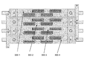
도 6은 150 dpi의 간격을 갖는 프린트 헤드들로부터 600 dpi 프린트를 제공하기 위해 배열된 모듈(300-1, 300-2, 300-3, 300-4)을 구비한 또 다른 실시예를 나타낸 것이고, 이 경우에 상기 모듈 각각은 실질적으로 도 4와 동일하나, 각각의 연속적인 모듈이 배치되거나, 상기 프린트 기판 운동 방향에 대하여 횡방향으로 대략 42㎛의 오프셋(offset)을 형성한다. 이 경우에, 스티칭(stitching)은 도 4에 따른 각 모듈에서 인접한 프린트 헤드들(300A, 300B 등) 사이에 수행되거나, 실질적으로 상기 기판 이동 방향(302)으로 서로 정렬되어 상호 배치된 프린트 헤드들의 4개의 집합 각각에 의해 프린트된 프린트의 띠(swathe)들 사이에 수행될 수 있다.
Figure 6 illustrates another embodiment with modules 300-1, 300-2, 300-3, and 300-4 arranged to provide 600 dpi prints from printheads having a spacing of 150 dpi , Wherein each of the modules in this case is substantially the same as in Fig. 4, but with each successive module disposed, or forming an offset of about 42 [mu] m in the transverse direction with respect to the printed board motion direction. In this case, stitching may be performed between
또 다른 프린트 헤드의 실시예(미도시)는 실질적으로 상기 프린트 헤드 폭의 1/4이 통로들 사이에 인덱싱된 단일 프린트 헤드를 이용할 수 있고, (a) 150 dpi 프린트 헤드로부터 600 dpi 프린트를 제공하며, (b) 전체 프린트 폭이 상기 프린트 헤드 폭 (인덱싱 모션의 수)보다 훨씬 크고, 따라서 통로들은 요구되는 전체 프린트 폭에 의해 결정된다. 이러한 경우에, 각 통로의 150 dpi 프린트의 띠(swathe)는 600 dpi 프린트를 만들도록 상호 배치된다. 150 dpi 띠들 사이의 중첩은 첫 번째, 다섯 번째, 아홉 번째 등의 통로/인덱세이션(passes/indexation) 사이에 나타나고, 상기 띠들의 스티치(stitching)는 이에 대응하여, 상기 (단일) 프린트 헤드의 반대쪽 단부들 사이에 첫 번째, 다섯 번째, 아홉 번째 상의 통로/인덱세이션(passes/indexation)에 나타나며; 유사하게, 150 dpi 띠의 스티치 및 중첩이 두 번째, 여섯 번째, 열 번째 등의 통로(passes) 사이에 나타나고, 세 번째, 일곱 번째, 열한 번째 등의 통로(passes) 사이 및 네 번째, 여덟 번째, 열두 번째 등의 통로(passes) 사이에 나타난다.
Another embodiment of the printhead (not shown) can utilize a single printhead that is substantially indexed between passages where a quarter of the printhead width is present, and (a) provides a 600 dpi print from a 150 dpi printhead (B) the total print width is much larger than the print head width (the number of indexing motions), and therefore the passages are determined by the total print width required. In this case, the swaths of the 150 dpi print of each passageway are interleaved to produce a 600 dpi print. The overlap between the 150 dpi strips appears between passes / indexations of the first, fifth, ninth, etc., and the stitching of the strips corresponds correspondingly to the Appears in the first, fifth, and ninth pass / indexations between the opposite ends; Similarly, stitches and overlaps of the 150 dpi band appear between passes of the second, sixth, tenth, and so on, and between passages of the third, seventh, eleventh, etc., and between the fourth and eighth , The twelfth, and so on.
모든 실시예에 있어서, 기판 위치 동기화 신호(예를 들어, 샤프트 인코더(shaft encoder)(216)(도 7에 나타남) 또는 기판 위치 서보(servo) 제어기로부터 발신됨)가 프린트 기판의 운동 방향을 따라 프린트 헤드들의 오프셋(offset)에 의한 적절한 시간에 액적이 프린트되는 것을 보장하기 위해 사용된다. 이러한 공정은 당해 기술 분야에서 잘 이해되며, 본 발명의 일부를 형성하지 않는다. 샤프트 인코더의 사용은, 이를 사용하지 않은 경우 다중 오프셋(offset) 프린트 헤드를 구비한 프린터 또는 단일 프린트 헤드 또는 프린트 헤드 모듈(그 자체가 다중 프린트 헤드를 구비함)을 구비한 프린터에 있어서, 상기 프린트 헤드(들)에 대한 상대적인 기판 속도의 변화 및 프린트 기판 운동의 방향에 대한 프린트 헤드들의 오프셋(offset)으로부터 발생하는 잠재적인 문제점을 해결한다.
In all embodiments, a substrate position synchronization signal (e.g., from a shaft encoder 216 (shown in FIG. 7) or a substrate position servo controller) is applied along the direction of motion of the printed substrate Is used to ensure that droplets are printed at the appropriate times by the offset of the print heads. Such processes are well understood in the art and do not form part of the present invention. The use of a shaft encoder, in a printer with a multi-offset printhead, or a single printhead, or a printer with a printhead module (which itself has multiple printheads) when not used, Solves potential problems arising from changes in the substrate speed relative to the head (s) and from the offset of the print heads relative to the direction of the print substrate motion.
본 발명의 방법에 따른 실시예를 설명하기 전에, Tonejet® 방법을 사용하여 프린트되는(또는 분사되는) 액적의 부피를 제어하기 위해 일반적으로 사용 가능한 두 가지 방법을 설명하는 것이 유용할 수 있다.
Before describing an embodiment according to the method of the present invention, it may be useful to describe two generally available methods for controlling the volume of droplets to be printed (or ejected) using the Tonejet® method.
도 12는 상기 프린트 헤드의 각 분사기(ejector) (업스탠드(2) 및 선단(21))에 대하여, 상기 분사 전압 펄스 VE의 진폭을 제어하기 위해 사용될 수 있는 회로(30)의 블록 다이어그램을 나타낸 것이고, 여기서 프린트될 상기 비트맵 픽셀의 값 Pn(8-비트 수, 즉 0 내지 225 사이의 값을 가짐)은 디지털-투-아날로그(digital-to-analogue) 변환기(31)에 의해서 저-전압 진폭으로 변환되고, 상기 변환기는 상기 프린트 헤드의 분사기에 인가되는 고-전압 펄스 VP의 길이를 정의하는 고정-길이의 펄스 VG에 의해 게이트되는 출력을 갖는다. 이러한 저-전압 펄스는 이어서 고-전압 선형 증폭기(32)에 의해서 증폭되어 상기 고-전압 펄스 VP를 산출하고, 이는 일반적으로 100 내지 400V의 진폭이며, 상기 픽셀의 비트-값에 의존하며, 결과적으로 바이어스 전압 VB 및 VIE 에 부가되어 분사 펄스 VE = VIE + VB + VP를 제공한다.
12 shows a block diagram of a
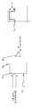
도 13은 상기 프린트 헤드의 각 분사기(ejector)에 대하여, 상기 분사 전압 펄스 VE의 길이(duration)를 제어하기 위해 사용될 수 있는 회로(30)의 블록 다이어그램을 나타낸 것이고, 여기서 프린트될 상기 비트맵 픽셀의 Pn 값은 프린트될 상기 픽셀의 시작 시에 "프린트 싱크(print sync)" 신호(PS)의 변환에 의해, 카운터(41) 내로 로딩되고, 상기 카운터의 출력(output)을 하이(high)로 설정하고; 상기 카운터에 (주기 T의) 연속적인 클록(clock) 사이클을 입력하여, 상기 카운터의 카운트가 0(zero)에 도달할 때까지 감소하도록 하여, 상기 카운터의 출력이 로우(low)로 리셋(reset)되도록 한다. 따라서, 상기 카운터의 출력은 픽셀 값(상기 픽셀 값 Pn 및 상기 클록의 주기 T의 곱)에 비례하는 길이(duration)를 갖는 로직 레벨(logic-level) 펄스 VPT이며; 이어서, 이 펄스는 로우일 때의 전압(VIE + VB)과 하이일 때의 전압(VIE + VB + VP) 사이에서 스위칭하여, 결과적으로 길이-제어된 분사 펄스 VE = VIE + VB + VP를 생성하는 고전압 스위칭 회로(42)에 의해 증폭된다.
13 shows a block diagram of a
프린트될 상기 비트맵 픽셀의 Pn 값은 (상기 분사 펄스의) 작동 주기(duty cycle)의 0% 내지 100%에 해당한다. 일반적으로, 이는 상기 프린트 기판 및 상기 프린트 헤드가 1ms-1의 속도로 상대적 운동을 하면서 600dpi의 해상도로 프린트 할 때, 42㎛의 펄스 반복 주기 상에서, 펄스 길이가 0 내지 42㎛인 것과 동일한 것으로 볼 수 있다.
The P n value of the bitmap pixel to be printed corresponds to 0% to 100% of the duty cycle (of the injection pulse). Generally, this is the same as when the print substrate and the print head are printed at a resolution of 600 dpi with a relative motion at a speed of 1 ms -1 , with a pulse length of 0 to 42 μm on a pulse repetition period of 42 μm, .
이들 대안 기술 중에서, 실제로 펄스의 길이를 변조하는 것이 더 간단하지만, 어느 하나의 기술이 주어진 환경에 적절할 수도 있고, 양자 모두가 함께 이용될 수도 있다.
Of these alternative techniques, it is simpler to actually modulate the length of the pulse, but either technique may be appropriate for a given environment, or both may be used together.
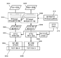
사용 중에, 본 발명에 따른 일 실시예는, 도 4, 7 및 8에 나타난 바와 같이, 예를 들어 어도브 일러스트레이터와 같은 공지의 다수의 이미지 생성 소프트웨어 패키지 중 어느 하나를 사용하여 형성된 컬러 이미지(200)가 컴퓨터(202)의 메모리(201) 내에 업로드 된다. 초기 이미지(200)는 이어서, 상기 컴퓨터(202) 내에서 이미지 처리 소프트웨어(203)(도 7 및 8 참조)를 사용하여 래스터화되고, 이어서 상응하는 컬러 비트맵 이미지(204)가 생성되고 메모리(205) 내에 저장된다. 이어서, 컬러 프로파일(206)이 상기 비트맵 이미지에 적용되어, 상기 프린트 처리의 토너 반응에 대한 교정(calibration)을 가능하게 하고, 이어서 각 픽셀이 '스크리닝(screened)' 또는 필터링(filtered)(207)되어 상기 픽셀의 각 컬러 성분이 다수의 상이한 '레벨들(levels)' 중 하나로 필터링되고, 이 경우에, CMYK n-레벨 이미지(208)로 나타나는 데이터가 램(209)에 저장되며, 각각의 주요 컬러 성분이 각각의 데이터 세트 (212c, 212m, 212y 및 212k)로 분리(210)된다.
In use, an embodiment in accordance with the present invention includes a
규정될 필요가 있는 프린트의 스트립(strip) 또는 띠(swathe)의 알려진 수가 제공되고, 이어서, 각 주요 컬러에 대한 그레이스케일 데이터(greyscale data)가 데이터 세트- 이 경우, 한 쌍의 중첩된 프린트 띠 또는 프린트 헤드(300A/300B)에 있어서 두 데이터 세트 302A, 302B로 스트립(213) 되어, 각각의 프린트 헤드 폭의 각 세로단(column)에 대한 픽셀 값(단일 프린트 헤드에 의해 제공되는 프린트 기판을 지나는 픽셀의 수)을 나타낸다. 이들 데이터 세트는 최종 이미지를 프린트 하기 위해 사용되는 개별 프린트 헤드(300A, 300B)의 분사 채널(301)에 대응하는 비트맵을 제공한다.
A known number of strips or swaths of the prints that need to be defined is provided and then the greyscale data for each primary color is provided to the data set - in this case, Or strips 213 into two sets of
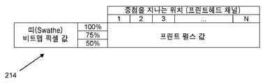
도 9는 인접한 프린트 헤드들 300A 및 300B에 의해 생성되는 단일 색상 분리(single colour separation)의 프린트 띠를 '스티칭'하는 과정을 나타낸 것이고, 구체적으로 픽셀 값에 대한 적절한 각각의 페이딩 함수를 적용한 것을 나타낸 것이다. 필요한 페이딩 함수는 메모리(215) 내에 보유된 대응되는 룩-업 데이블(214)에 저장된다. 각 색상에 대한 픽셀 값의 각 레벨은 일반적으로 상기 룩-업 테이블(214)에서 각각의 페이딩 함수를 보유할 것이다. 이어서, 각각의 페이딩 함수는 각각의 헤드(300A, 300B)에 대하여, 이의 색상 및 펄스 길이 값 (또는 펄스 진폭 값 또는 양자 모두)을 생성하는 레벨에 따라 상기 비트맵 데이터세트 내의 각 픽셀에 적용(303A/303B)되어 각각의 프린트 헤드 펄스 데이터세트(304A, 304B)를 형성한다.
FIG. 9 illustrates the process of 'stitching' printbands of a single color separation produced by
이어서, 상기 펄스 데이터(304A, 304B)는 (상기 샤프트 인코더(216)에 의해 결정된) 상기 프린트 기판 및 상기 프린트 헤드의 상대적인 위치에 따라서, 305A/305B 단계로 전송되고, 드라이버 카드(펄스 생성 전자 장치)(306A, 306B)로 전송되어, 여기서 상기 데이터가 각각의 프린트 헤드 분사 채널(301)에 필요에 따라 적용되어 구동 펄스의 길이를 결정하기 위해 활용되며, 각 픽셀의 펄스 데이터에 따라 소정의 길이(duration) 및/또는 진폭을 갖는 전압 펄스가 생성된다. 상기 데이터는 상기 기판 위치 및 하나의 프린트 헤드(300A)와 중첩된 인접한 프린트 헤드(300B)의 분사 채널(301)의 오프셋(offset)에 대하여, 시간-의존성으로 전송된다.
The
상기 페이딩 함수의 생성 및 적용의 과정은 이제 상기 기판의 폭에 걸쳐서 중첩된 두 헤드를 갖는 원통형(cylindrical) 기판을 프린트 하기 위한 중첩된 프린트 헤드의 인칭 당 2개의 150 채널의 4개의 통로를 사용하는 실시예로서 설명될 것이고, 상기 기판은 600 dpi의 완전한 범위를 인쇄하기 위해서 4회 회전할 것이다. 상기 설명된 페이딩 기술은 상기 기판 위에 하나 또는 그 이상의 통로를 형성하는 다중 또는 단일 프린트 헤드의 중첩된 부분에 직접적으로 적용 가능하다.
The process of generating and applying the fading function now uses four channels of two 150 channels per inch of overlapping printheads for printing a cylindrical substrate with two heads overlapping over the width of the substrate Will be described as an example, and the substrate will rotate four times to print a complete range of 600 dpi. The fading technique described above is directly applicable to overlapping portions of multiple or single printheads forming one or more passageways over the substrate.
기재된 구체적인 실시예에서 중첩된 10개의 프린트 헤드 채널(40 픽셀)이 사용된다. 그러나, 중첩 영역의 폭은 합쳐진 부분의 가시성(visibility)에 영향을 미친다: 일반적으로 중첩이 클수록, 더 많은 오류를 분산시킬 수 있고, 합쳐진 부분이 덜 보이게 된다. 이는 프린트 폭을 최대화하기 위한 최소의 중첩에 대한 요구와 균형을 이루어야 한다.
In the described specific embodiment, ten superimposed printhead channels (40 pixels) are used. However, the width of the overlap region affects the visibility of the merged portion: in general, the larger the overlap, the more errors can be scattered and the merged portion becomes less visible. This should be balanced against the need for minimal overlay to maximize the print width.
필요한 페이딩 함수를 준비하기 위하여, 일련의 테스트 이미지들이 단일 프린트 헤드들을 사용하여 제조되고, 실험적으로 가장 효과적인 것을 결정하기 위하여 페이딩 함수를 선택하여 프린트된다. 상기 이미지를 표준 4단계 오류 분산 방법을 이용하여 스크리닝하고, 상기 이미지를 프린트에 필요한 최대 광학 밀도를 제공하는 최대 도트(dot) 크기의 0%, 50%, 75% 및 100%의 크기로 나타낸다. 초기 함수 파라미터가 추정되었고, 프린트 품질이 수용 가능할 때까지 반복되었다. 상기 파라미터는 하기 사항에 따라 결정되었다:To prepare the required fading function, a series of test images are produced using single printheads, and the fading function is selected and printed to determine which is the most empirically effective. The image is screened using a standard four-step error-distribution method and represented as 0%, 50%, 75%, and 100% of the maximum dot size that provides the image with the maximum optical density required for printing. Initial function parameters were estimated and repeated until print quality was acceptable. The parameters were determined according to the following:

자세하게는, 파라미터의 마지막 반복에 해당하는 펄스 길이의 곡선이 도 10에 플롯되어 나타난다.
Specifically, the curve of the pulse length corresponding to the last iteration of the parameter is plotted in Fig.
전술한 바와 같이, 이 실시예에서, 각 액적 부피 크기 레벨에 대하여, 후술하는 식의 페이딩 함수가 프린트 A 및 B의 두 프린트 헤드/띠 (300A, 300B)의 중첩 영역을 지나는 페이드의 프로파일을 정의하기 위해 사용되었다:
As described above, in this embodiment, for each droplet volume magnitude level, a fading function of the formula described below defines a fade profile across the overlapping areas of the two printheads /
![]()
![]()
![]()
![]()
상기 f A 는 프린트 헤드/띠 A의 페이딩 함수이고,remind f A is the fading function of the printhead / stripe A,
상기 f B 는 프린트 헤드/띠 B의 페이딩 함수이며, 이는 f A 의 거울 이미지(mirror-image)이다. F B is the fading function of the printhead / band B, which is a mirror-image of f A.
상기 fmin 는 상기 페이딩 함수의 최소 값으로, 최소 프린트 가능한 레벨을 제공한다. Fmin is the minimum value of the fading function and provides a minimum printable level.
상기 x 는 중첩 위치를 지나는 표준화 위치이고, 0 = x = 1이다. X is a normalization position passing through the overlapping position, and 0 = x = 1.
상기 α는 상기 페이딩 함수의 힘(power)이다.
Is the power of the fading function.
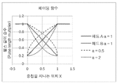
페이딩 함수의 예시가 도 11에 플롯되어 나타난다. 상기 함수는 α= 1에 대하여 선형 페이드를 제공하고, α< 1에 대하여 볼록한 곡선을 제공하며, α> 1에 대하여 오목한 곡선을 제공한다. 도 11은 α= 1, 0.5 및 2인 페이딩 함수를 나타내며, 이때 f min 는 0.2로 설정된다.
An example of the fading function is plotted in FIG. The function provides a linear fade for? = 1, provides a convex curve for? <1, and provides a concave curve for?> 1. 11 is α = 1, represents a 0.5 second and the fading function, where f min is set to 0.2.
상기 페이딩 함수는 상기 이미지 픽셀의 값에 곱함으로써 상기 이미지 데이터에 적용된다. 이는 스크리닝(screening) 이후 즉, 상기 픽셀 값이 별도로 계산된 이후에 상기 이미지 데이터에 적용되며, 제어 컴퓨터 상의 래스터 이미지 처리기(Raster Image Processing) 또는 프린트 헤드 구동 장치에 적용될 수 있다. 상기 페이딩 함수가 그레이 레벨/액적 부피 크기에 의존하므로, 주어진 픽셀에 적용되는 함수가 그 픽셀의 스크리닝된 값에 따라 선택된다. 예를 들어, 50% 레벨의 픽셀은 50% 레벨용 페이딩 함수에 의해 곱해질 것이다. 그러므로, 페이딩 함수의 집합(family)은 스크리닝된 이미지 내에서 0(zero)이 아닌 부피 사이즈만큼 많은 곡선들을 함유하게 된다(예를 들어, 4-레벨의 이미지에 대해서는 3; 8-레벨의 이미지에 대해서는 7).
The fading function is applied to the image data by multiplying the value of the image pixel. This can be applied to the image data after screening, i. E. After the pixel values have been calculated separately, and to a raster image processing (Raster Image Processing) or printhead driving device on a control computer. Since the fading function depends on the gray level / droplet volume magnitude, the function applied to a given pixel is selected according to the screened value of that pixel. For example, a 50% level pixel will be multiplied by a 50% level fading function. Therefore, the family of fading functions will contain as many curves as the volume size, not zero, in the screened image (e.g., for a 4-level image, a 3: 8- 7).
이미지 픽셀의 레벨 PL과 그 레벨용 페이딩 함수를 곱하여 산출된 픽셀 값은 하기와 같이 도출된다:
The pixel value calculated by multiplying the level P L of the image pixel by the fading function for that level is derived as follows:
일면(B)에 대한 일반적 페이딩 함수를 선택:Select the normal fading function for one side (B):
![]()
![]()
스크리닝된 이미지 내의 각 픽셀 레벨 L에 대한 페이딩 함수 f L (x):The fading function f L ( x ) for each pixel level L in the screened image:
![]()
![]()
상기 이미지를 지나는 위치 x의 픽셀 레벨 L은 이의 값 P L 에 이의 레벨에 대한 페이딩 함수를 곱함으로써 페이딩된다:
The pixel level L of the position x passing through the image has its value P L Is faded by multiplying it by its fading function:
![]()
![]()
![]()
![]()
![]()
![]()
여기서, ![]()
![]()
P minL 은 최소 요구되는 픽셀 값이고, 이는 대략적으로 픽셀의 본래 값 P L 과 동일하다.
P minL Is the minimum required pixel value, which is approximately the original value P L of the pixel .
따라서, 상기 픽셀 값은 이미지 픽셀의 레벨 P L 을 그 레벨의 페이딩 함수와 곱함으로써 산출된다:
Thus, the pixel value is the level P L By the fading function of that level: < RTI ID = 0.0 >
![]()
![]()
![]()
![]()
여기서, P A 는 헤드/띠 A의 상기 픽셀의 수정된 값이다.Where P A is the modified value of the pixel of head / stripe A.
P B 는 헤드/띠 B의 상기 픽셀의 수정된 값이다. P B is the modified value of the pixel of head / band B.
P minL 는 상기 픽셀에 대하여 최소 요구되는 값이다.
P minL Is the minimum required value for the pixel.
Claims (21)
상기 이미지의 각 행에 대하여, 중첩되는 분사 채널(301)에 의해 프린트된 픽셀을 형성하기 위해 상기 중첩된 프린트 헤드에 인가되는 전압 펄스(VE)의 값은, 상기 프린트 헤드(300)의 중첩되는 영역 내의 상기 픽셀의 위치 및 상기 픽셀의 소정의 부피 크기에 의존하는 것을 특징으로 하는 방법.
A method of printing a two-dimensional bitmap image having a plurality of pixels per row by printing using a plurality of overlapping printheads 300 or one printhead or printheads indexed along an overlapping position , Or each of the printheads has a row of ejection channels 301 and each of the jetting channels is configured such that particulate concentration is formed from the body of the print fluid in use Wherein a volume of charged particulate aggregate ejected as a printed droplet from a selected one of the overlapping print heads is applied to one of a plurality of predetermined volume sizes In order to be formed, each predetermined amplitude and length (durati) determined by each image pixel bit value on voltage pulse (V E ) is applied to the selected injection channel,
For each row of the image, the value of the voltage pulse (V E ) applied to the superposed print head to form a pixel printed by the overlapping jet channel (301) The position of the pixel in the region of interest and the predetermined volume size of the pixel.
상기 복수의 중첩된 프린트 헤드(300)는 사용 시 서로 상대적인 위치에 고정되는
방법.
The method according to claim 1,
The plurality of overlapping printheads 300 are fixed in position relative to one another in use
Way.
상기 복수의 중첩된 프린트 헤드(300)는 프린트 기판 위의 초기 통로(first pass) 상에 프린트하는 제1 프린트 헤드(a first printhead) 및 이와 동일하거나 다른 프린트 헤드로서, 상기 프린트 기판 위의 나중 통로(later pass) 상에 프린트하고, 상기 제1 프린트 헤드의 위치와 위치 상으로 중첩되는 프린트 헤드를 포함하는
방법.
The method according to claim 1,
The plurality of overlapping printheads 300 may include a first printhead that prints on an initial pass over the print substrate and the same or a different printhead, and a print head which overlies the position of the first print head with the print head on a later pass,
Way.
상기 제1 프린트 헤드(300)는 상기 기판 위의 통로들 사이에 상기 프린트 헤드 채널(301)의 행의 폭보다 적은 간격과 동일한 간격으로 인덱싱되어 원하는 중첩을 이루는
방법.
The method of claim 3,
The first printhead 300 is indexed between passages on the substrate at an interval equal to less than the width of the rows of the printhead channels 301 to form the desired overlap
Way.
각 프린트 헤드(300)는 서로 평행하면서, 인접한 분사 채널(301) 간 간격의 일정 부분이 오프셋(offset)되도록 모듈 내에 배치된 다수의 동일한 프린트 헤드들 중 하나이고, 이로써 프린트된 이미지가 인접한 분사 채널 사이 간격보다 더 큰 해상도(resolution)를 갖게 되는
방법.
The method according to claim 1,
Each printhead 300 is one of a plurality of identical printheads disposed in the module such that a parallel portion of the printheads 300 is offset and a portion of the spacing between adjacent jetting channels 301 is offset, Having a resolution greater than the spacing between them
Way.
상기 복수의 모듈(300-1 내지 300-4)은 하나가 다른 하나와 중첩되어 프린트의 폭을 개별 모듈의 폭보다 커지도록 하는
방법.
6. The method of claim 5,
One of the plurality of modules 300-1 to 300-4 is overlapped with the other to make the width of the print larger than the width of the individual module
Way.
상기 모듈(300)은 기판 위의 통로들 사이에 프린트 헤드의 채널의 행의 폭보다 적은 간격과 동일한 간격으로 인덱싱되어 원하는 중첩을 이루는
방법.
6. The method of claim 5,
The module 300 is indexed between passages on the substrate at an interval equal to less than the width of the row of channels of the printhead,
Way.
상기 프린트 헤드(300)는 인접한 분사 채널(301) 간 간격의 일정 부분에 의해 인덱싱되어, 이로써 프린트된 이미지가 인접한 분사 채널 사이 간격보다 더 큰 해상도(resolution)를 갖게 되는
방법.
The method of claim 3,
The printhead 300 is indexed by a portion of the spacing between adjacent firing channels 301 such that the printed image has a resolution greater than the spacing between adjacent firing channels
Way.
상기 중첩된 프린트 헤드(300)에 인가되는 전압 펄스(VE)의 값은 상기 프린트 헤드의 중첩 영역에 프린트 될 픽셀의 소정의 부피 크기의 레벨에 의존하는 소정의 페이딩 함수로부터 결정되는
방법.
9. The method according to any one of claims 1 to 8,
The value of the voltage pulse V E applied to the superimposed printhead 300 is determined from a predetermined fading function that depends on the level of the predetermined volume magnitude of the pixel to be printed in the overlap region of the printhead
Way.
상기 픽셀 비트 값은, 상기 픽셀 값을, 프린트를 위한 각각의 소정의 진폭(amplitude) 및 길이(duration)의 전압 펄스로 변환하기 전에, 상기 프린트 헤드들(300)의 중첩 영역 내의 상기 픽셀의 위치 및 상기 픽셀의 소정의 부피 크기에 따라 조정되는
방법.
10. The method according to any one of claims 1 to 9,
The pixel bit value is used to determine the position of the pixel in the overlap region of the print heads 300 before converting the pixel value into a voltage pulse of each predetermined amplitude and duration for printing. And adjusting the size of the pixel according to a predetermined volume size
Way.
상기 이미지의 픽셀 비트 값은 상기 값을 전압 펄스(VE)로 변환하는 프린트 헤드 구동 전자 장치(printhead drive electronics)(306A, 306B)에 제공될 수 있고, 그 안에서 상기 전압 펄스 값이, 상기 프린트 헤드의 분사 전극에 인가되기 전에, 상기 프린트 헤드들(300)의 중첩 영역 내 픽셀의 위치 및 상기 픽셀의 소정의 부피 크기에 의해 결정되는
방법.
10. The method according to any one of claims 1 to 9,
The pixel bit value of the image may be provided to printhead drive electronics 306A, 306B that convert the value to a voltage pulse V E , Is determined by the position of the pixel in the overlap region of the printheads 300 and the predetermined volume size of the pixel before being applied to the ejection electrode of the head
Way.
상기 이미지의 각 행에 대하여, 중첩되는 분사 채널(301)에 의해 프린트된 픽셀을 형성하기 위해 상기 중첩되는 프린트 헤드(300)에 인가되는 전압 펄스의 값은, 상기 프린트 헤드의 중첩 영역 내의 상기 픽셀의 위치 및 상기 픽셀의 소정의 부피 크기에 의존하는 것을 특징으로 하는 장치.
A device for printing a two-dimensional bitmap image having a plurality of pixels per row, the device comprising a plurality of overlapping printheads (300) or one printhead or printhead Wherein each or each of the printheads has a row of jetting channels 301 and each jetting channel has a voltage sufficient to cause particulate concentration to form in the body of the print fluid in use Wherein each of the plurality of overlapping printheads has an associated associated ejection electrode, wherein in order to allow the volume of charged particulate aggregate ejected as printed droplets from a selected one of the overlapping printheads to be formed into one of a plurality of predetermined volume sizes, Voltage pulses (V E ) of each predetermined amplitude and duration determined by the pixel bit value are stored in phase Is applied to the previously selected injection channel,
For each row of the image, the value of the voltage pulse applied to the overlapping print head (300) to form a pixel printed by the overlapping injection channel (301) And a predetermined volume size of the pixel.
상기 복수의 중첩된 프린트 헤드(300)는 사용 시 서로 상대적인 위치에 고정되는
장치.
The method according to claim 1,
The plurality of overlapping printheads 300 are fixed in position relative to one another in use
Device.
프린트 기판 위의 초기 통로(first pass) 상에 프린트하기 위해 배열된 제1 프린트 헤드(a first printhead) 및 이와 동일하거나 또 다른 프린트 헤드로서, 상기 프린트 기판 위의 나중 통로(later pass) 상에 프린트하고, 상기 제1 프린트 헤드의 위치와 위치 상으로 중첩되는 프린트 헤드를 포함하는
장치.
13. The method of claim 12,
A first printhead and the same or another printhead arranged to print on an initial pass over a printed substrate, the print head having a first print head and a second print head printed on a later pass on the print substrate, And a print head superimposed on the position of the first print head,
Device.
상기 제1 프린트 헤드(300)는 기판 위의 통로들 사이에 프린트 헤드의 채널의 행의 폭보다 적은 간격과 동일한 간격으로 인덱싱되어 원하는 중첩을 이루도록 배열된
장치.
15. The method of claim 14,
The first printhead 300 is indexed between passages on the substrate at equal intervals of less than the width of the row of channels of the printhead,
Device.
각 프린트 헤드(300)는 서로 평행하면서, 인접한 분사 채널(301) 간 간격의 일정 부분이 오프셋(offset)되도록 모듈 내에 배치된 다수의 동일한 프린트 헤드들 중 하나이고, 이로써 프린트된 이미지가 인접한 분사 채널 사이 간격보다 더 큰 해상도(resolution)를 갖게 되는
장치.
13. The method of claim 12,
Each printhead 300 is one of a plurality of identical printheads disposed in the module such that a parallel portion of the printheads 300 is offset and a portion of the spacing between adjacent jetting channels 301 is offset, Having a resolution greater than the spacing between them
Device.
상기 복수의 모듈(300)은 하나가 다른 하나와 중첩되어 프린트의 폭을 개별 모듈의 폭보다 커지도록 하는
장치.
17. The method of claim 16,
The plurality of modules 300 are stacked one over the other so that the width of the prints is greater than the width of the individual modules
Device.
상기 모듈(300)은 기판 위의 통로들 사이에 상기 프린트 헤드 채널의 행의 폭보다 적은 간격과 동일한 간격으로 인덱싱되어 원하는 중첩을 이루도록 배열된
장치.
17. The method of claim 16,
The module 300 may be indexed between passageways on the substrate at intervals equal to less than the width of the rows of the printhead channels,
Device.
상기 프린트 헤드(300)는 인접한 분사 채널 간 간격의 일정 부분에 의해 인덱싱되어, 이로써 프린트된 이미지가 인접한 분사 채널 사이 간격보다 더 큰 해상도(resolution)를 갖게 되는
장치.
15. The method of claim 14,
The printhead 300 is indexed by a portion of the interval between adjacent firing channels such that the printed image has a resolution greater than the spacing between adjacent firing channels
Device.
An apparatus for performing the method according to any one of the preceding claims.
상기 장치는 제12항 내지 제19항 중 어느 한 항에 따르는 장치.21. The method of claim 20,
The apparatus according to any one of claims 12 to 19.
Applications Claiming Priority (2)
| Application Number | Priority Date | Filing Date | Title |
|---|---|---|---|
| EP12169098.6A EP2666636B1 (en) | 2012-05-23 | 2012-05-23 | Printhead control |
| PCT/EP2013/063494 WO2013175024A2 (en) | 2012-05-23 | 2013-06-27 | Printhead control |
Publications (1)
| Publication Number | Publication Date |
|---|---|
| KR20160014506A true KR20160014506A (en) | 2016-02-11 |
Family
ID=46149245
Family Applications (1)
| Application Number | Title | Priority Date | Filing Date |
|---|---|---|---|
| KR1020147034711A KR20160014506A (en) | 2012-05-23 | 2013-06-27 | Printhead control |
Country Status (13)
| Country | Link |
|---|---|
| US (1) | US9352556B2 (en) |
| EP (1) | EP2666636B1 (en) |
| JP (1) | JP2015527213A (en) |
| KR (1) | KR20160014506A (en) |
| CN (1) | CN104395088B (en) |
| AU (1) | AU2013265178B2 (en) |
| BR (1) | BR112014029017A2 (en) |
| ES (1) | ES2688076T3 (en) |
| IL (1) | IL235613B (en) |
| IN (1) | IN2014DN09609A (en) |
| PL (1) | PL2666636T3 (en) |
| PT (1) | PT2666636T (en) |
| WO (1) | WO2013175024A2 (en) |
Cited By (3)
| Publication number | Priority date | Publication date | Assignee | Title |
|---|---|---|---|---|
| KR20230130242A (en) | 2022-03-03 | 2023-09-12 | 에이치비솔루션㈜ | Profile feedback patterning system for reducing stitch mura of multi head inkjet printing |
| KR20230130246A (en) | 2022-03-03 | 2023-09-12 | 에이치비솔루션㈜ | UV blocking mask system for reducing stitch mura of multi head inkjet printing |
| KR20230130243A (en) | 2022-03-03 | 2023-09-12 | 에이치비솔루션㈜ | LED control system for reducing stitch mura of multi head inkjet printing |
Families Citing this family (4)
| Publication number | Priority date | Publication date | Assignee | Title |
|---|---|---|---|---|
| EP3197684B1 (en) | 2014-09-24 | 2021-11-03 | Hewlett-Packard Development Company, L.P. | Replaceable integrated printhead cartridge |
| CN107077628B (en) * | 2014-11-13 | 2020-06-26 | 惠普发展公司,有限责任合伙企业 | Printer and computer-implemented process for controlling a printer |
| US11884020B2 (en) * | 2017-12-27 | 2024-01-30 | Stratasys Ltd. | Print head and method of calibrating the same |
| CN113511007B (en) * | 2020-04-11 | 2022-10-21 | 深圳市汉森软件有限公司 | Method, device and equipment for eliminating nozzle splicing error and storage medium |
Family Cites Families (20)
| Publication number | Priority date | Publication date | Assignee | Title |
|---|---|---|---|---|
| AU664404B2 (en) | 1991-12-18 | 1995-11-16 | Tonejet Limited | Method and apparatus for the production of discrete agglomerations of particulate matter |
| GB9601226D0 (en) | 1996-01-22 | 1996-03-20 | The Technology Partnership Plc | Ejection apparatus and method |
| GB9601223D0 (en) | 1996-01-22 | 1996-03-20 | The Technology Partnership Plc | Electrode for printer |
| US6158844A (en) * | 1996-09-13 | 2000-12-12 | Kabushiki Kaisha Toshiba | Ink-jet recording system using electrostatic force to expel ink |
| GB9701318D0 (en) | 1997-01-22 | 1997-03-12 | Tonejet Corp Pty Ltd | Ejection apparatus |
| EP0914950A3 (en) * | 1997-11-06 | 1999-12-08 | Xerox Corporation | An ink jet printhead assembled from partial width array printheads |
| EP1095772A1 (en) | 1999-10-25 | 2001-05-02 | Tonejet Corporation Pty Ltd | Printhead |
| US7388686B2 (en) * | 2003-02-25 | 2008-06-17 | Zink Imaging, Llc | Image stitching for a multi-head printer |
| US6540315B1 (en) * | 2002-01-16 | 2003-04-01 | Xerox Corporation | Systems and methods for stitching overlapping swaths |
| EP1366901B1 (en) | 2002-05-31 | 2005-09-14 | Tonejet Limited | Printhead |
| JP2005297295A (en) * | 2004-04-09 | 2005-10-27 | Fuji Photo Film Co Ltd | Inkjet recording method |
| US7413272B2 (en) * | 2004-11-04 | 2008-08-19 | Applied Materials, Inc. | Methods and apparatus for precision control of print head assemblies |
| JP4618789B2 (en) * | 2005-03-24 | 2011-01-26 | キヤノン株式会社 | Inkjet recording apparatus and inkjet recording method |
| JP2007007949A (en) * | 2005-06-29 | 2007-01-18 | Fujifilm Holdings Corp | Active energy curing ink jet recorder and its recording method |
| US8235489B2 (en) * | 2008-05-22 | 2012-08-07 | Fujifilm Dimatix, Inc. | Ink jetting |
| JP5298710B2 (en) * | 2008-09-01 | 2013-09-25 | セイコーエプソン株式会社 | Fluid ejecting apparatus and fluid ejecting method |
| US7871145B1 (en) * | 2009-07-20 | 2011-01-18 | Eastman Kodak Company | Printing method for reducing stitch error between overlapping jetting modules |
| JP5717346B2 (en) * | 2010-01-29 | 2015-05-13 | キヤノン株式会社 | Image processing apparatus, image processing method, recording apparatus, and recording method |
| JP5811516B2 (en) * | 2010-04-07 | 2015-11-11 | セイコーエプソン株式会社 | Correction value acquisition method, correction value acquisition program, and printing apparatus. |
| JP5481446B2 (en) * | 2011-08-31 | 2014-04-23 | 富士フイルム株式会社 | Liquid discharge head and liquid discharge apparatus |
-
2012
- 2012-05-23 EP EP12169098.6A patent/EP2666636B1/en not_active Not-in-force
- 2012-05-23 PT PT12169098T patent/PT2666636T/en unknown
- 2012-05-23 ES ES12169098.6T patent/ES2688076T3/en active Active
- 2012-05-23 PL PL12169098T patent/PL2666636T3/en unknown
-
2013
- 2013-06-27 WO PCT/EP2013/063494 patent/WO2013175024A2/en active Application Filing
- 2013-06-27 CN CN201380027216.0A patent/CN104395088B/en not_active Expired - Fee Related
- 2013-06-27 JP JP2015513229A patent/JP2015527213A/en active Pending
- 2013-06-27 US US14/403,045 patent/US9352556B2/en active Active
- 2013-06-27 AU AU2013265178A patent/AU2013265178B2/en not_active Ceased
- 2013-06-27 BR BR112014029017A patent/BR112014029017A2/en not_active Application Discontinuation
- 2013-06-27 IN IN9609DEN2014 patent/IN2014DN09609A/en unknown
- 2013-06-27 KR KR1020147034711A patent/KR20160014506A/en not_active Application Discontinuation
-
2014
- 2014-11-10 IL IL235613A patent/IL235613B/en active IP Right Grant
Cited By (3)
| Publication number | Priority date | Publication date | Assignee | Title |
|---|---|---|---|---|
| KR20230130242A (en) | 2022-03-03 | 2023-09-12 | 에이치비솔루션㈜ | Profile feedback patterning system for reducing stitch mura of multi head inkjet printing |
| KR20230130246A (en) | 2022-03-03 | 2023-09-12 | 에이치비솔루션㈜ | UV blocking mask system for reducing stitch mura of multi head inkjet printing |
| KR20230130243A (en) | 2022-03-03 | 2023-09-12 | 에이치비솔루션㈜ | LED control system for reducing stitch mura of multi head inkjet printing |
Also Published As
| Publication number | Publication date |
|---|---|
| EP2666636B1 (en) | 2018-08-08 |
| WO2013175024A8 (en) | 2014-03-13 |
| AU2013265178B2 (en) | 2016-07-14 |
| AU2013265178A1 (en) | 2014-11-27 |
| BR112014029017A2 (en) | 2017-06-27 |
| EP2666636A1 (en) | 2013-11-27 |
| CN104395088A (en) | 2015-03-04 |
| PL2666636T3 (en) | 2018-11-30 |
| ES2688076T3 (en) | 2018-10-30 |
| CN104395088B (en) | 2017-02-22 |
| IN2014DN09609A (en) | 2015-07-31 |
| US20150138280A1 (en) | 2015-05-21 |
| US9352556B2 (en) | 2016-05-31 |
| IL235613A0 (en) | 2015-01-29 |
| JP2015527213A (en) | 2015-09-17 |
| PT2666636T (en) | 2018-10-23 |
| IL235613B (en) | 2019-08-29 |
| WO2013175024A2 (en) | 2013-11-28 |
| WO2013175024A3 (en) | 2014-05-08 |
Similar Documents
| Publication | Publication Date | Title |
|---|---|---|
| EP2895332B1 (en) | Printhead calibration and printing | |
| US8031367B2 (en) | Ejection device and ejection method with uneven liquid ejection control effect | |
| KR20160014506A (en) | Printhead control | |
| US9333745B2 (en) | Printing control apparatus and printing control method | |
| US10940695B2 (en) | Printing apparatus and printing method | |
| US9463639B1 (en) | Printhead control | |
| EP2835263B1 (en) | Dot recording apparatus, dot recording method, and computer program therefor | |
| JP6910327B2 (en) | Printhead control | |
| CN109572227B (en) | Printing control device, printing device, and printing control method | |
| JP6197227B2 (en) | Printhead calibration and printing | |
| KR101500053B1 (en) | Image and printhead control | |
| JP2019006122A5 (en) | ||
| JP2005246861A (en) | Ejection controller, ejection control method, printer, image signal processor, program, and recording medium |
Legal Events
| Date | Code | Title | Description |
|---|---|---|---|
| A201 | Request for examination | ||
| E902 | Notification of reason for refusal | ||
| E601 | Decision to refuse application |