KR20160004695A - The sunlight shutter - Google Patents

The sunlight shutter Download PDF

Info

Publication number
KR20160004695A
KR20160004695A KR1020140083507A KR20140083507A KR20160004695A KR 20160004695 A KR20160004695 A KR 20160004695A KR 1020140083507 A KR1020140083507 A KR 1020140083507A KR 20140083507 A KR20140083507 A KR 20140083507A KR 20160004695 A KR20160004695 A KR 20160004695A
Authority
KR
South Korea
Prior art keywords
frame
window
rainwater
bottom frame
side frames
Prior art date
Legal status (The legal status is an assumption and is not a legal conclusion. Google has not performed a legal analysis and makes no representation as to the accuracy of the status listed.)
Abandoned
Application number
KR1020140083507A
Other languages
Korean (ko)
Inventor
김희정
Original Assignee
김희정
Priority date (The priority date is an assumption and is not a legal conclusion. Google has not performed a legal analysis and makes no representation as to the accuracy of the date listed.)
Filing date
Publication date
Application filed by 김희정 filed Critical 김희정
Priority to KR1020140083507A priority Critical patent/KR20160004695A/en
Publication of KR20160004695A publication Critical patent/KR20160004695A/en
Abandoned legal-status Critical Current

Links

Images

Landscapes

  • Securing Of Glass Panes Or The Like (AREA)

Abstract

본 발명은 차단부재는 빗물막이 또는 바람막이 등을 창문틀에 쉽게 설치하고 해체할 수 있도록 하고 상기 창문틀의 형상이나 크기에 관계없이 빗물막이나 바람막이 등을 간편하게 탈부착할 수 있도록 함으로서 편의성 및 효율성을 높인 창문에 탈착 가능하게 설치되는 차단부재를 제공한다.
이를 구현하기 위한 본 발명은 창벽틀에 수직으로 세워진 상태로 설치되며 내면에는 삽입홈을 사이에 두고 가이드돌기가 돌출 형성된 제 1측면프레임과, 창문틀에 수직으로 세워진 상태로 설치되며 외면에는 상기 창문틀이 끼워지기 위한 수용홈이 형성되고 그 내면에는 삽입홈을 사이에 두고 가이드돌기가 돌출 형성된 제 2측면프레임과, 창문바닥틀에 수평으로 누운 상태로 설치되며 바닥면에는 상기 창문바닥틀에 설치되어 있는 레일이 끼워지기 위한 레일삽입홈이 형성되고 그 상면에는 삽입홈을 사이에 두고 가이드돌기가 돌출 형성된 바닥프레임 및 상기 제 1, 2측면프레임과 바닥프레임 사이에 위치하며 그 양측 및 하단을 상기 제 1, 2측면프레임의 삽입홈과 상기 바닥프레임의 삽입홈에 각각 끼워넣어 조립 구성하는 차단판을 포함하여 구성한 것을 기술적 요지로 한다.
In the present invention, it is possible to easily install and dismantle a rainwater or windshield on a window frame, and to easily attach and detach rainwater or windshield irrespective of the shape and size of the window frame, thereby improving convenience and efficiency A blocking member detachably installed in a window is provided.
In order to achieve the above object, according to the present invention, there is provided a portable terminal, comprising: a first side frame installed vertically on a window frame and having a guide protrusion protruding from an inner surface thereof with an insertion groove interposed therebetween; A second side frame formed on the inner surface thereof with a guide protrusion protruding therebetween through a receiving groove for receiving the frame, and a second side frame provided on the floor bottom so as to be laid horizontally on the window floor frame, A bottom frame having a guide groove formed at an upper surface thereof and having a guide protrusion protruding therebetween, and a pair of guide grooves disposed between the first and second side frames and the bottom frame, And a shield plate which is assembled by being inserted into the insertion grooves of the first and second side frames and the insertion grooves of the bottom frame And as a technical base.

Description

창문에 탈착 가능하게 설치되는 차단부재{The sunlight shutter} [0001] The present invention relates to a shutter member detachably mounted on a window,

본 발명은 빗물이 유입되는 것을 방지하는 빗물막이, 창문을 열었을 때 사생활을 보호하면서 바람의 흐름을 원활하게 하는 시선막이(또는 바람막이) 등을 창문틀에 설치할 수 있도록 하는 창문에 탈착 가능하게 설치되는 차단부재에 관한 것으로서, 더욱 상세하게는 상기 빗물막이 또는 바람막이 등을 창문틀에 쉽게 설치하고 해체할 수 있도록 하고 상기 창문틀의 형상이나 크기에 관계없이 빗물막이나 바람막이 등을 간편하게 탈부착할 수 있도록 하는 편의성과 효율성을 모두 갖춘 창문에 탈착 가능하게 설치되는 차단부재에 관한 것이다.
The present invention relates to a rainwater damper for preventing rainwater from flowing in, and a windshield (or a windshield) for smoothly flowing wind while protecting the privacy of the windshield when the windshield is opened, More particularly, the present invention relates to a shielding member, and more particularly, to a shielding member capable of easily installing and disassembling the rainwater or windshield on a window frame, and capable of easily attaching and detaching a rainwater film or a windshield regardless of the shape and size of the window frame To a blocking member detachably installed in a window having both convenience and efficiency.

한편, 본 발명에서 구현하고자 하는 창문들을 이용한 탈부착식 차단판 구조는 위에서 보았듯이 빗물이 유입되는 것을 방지하는 빗물막이나 창문을 열었을 때 외부의 사람의 시선으로부터 사생활을 보호하면서 밖에서 불어오는 바람이 실내로 원활하게 유입될 수 있도록 하는 시선막이(또는 바람막이) 등과 같은 모든 차단장치에 적용할 수 있다는 것을 미리 밝혀두는 바이다.Meanwhile, the detachable blocking plate structure using the windows to be implemented in the present invention can prevent the rainwater from entering the window as seen from above, and protect the private life from the sight of the outside person when the window is opened, (Or a windshield) that allows the gas to flow smoothly into the gas-liquid separator, and the like.

따라서, 하기의 상세한 설명에서는 당 업계에서 평균적인 지식을 가진 자가 본 발명을 보다 용이하게 이해할 수 있도록 하기 위하여 구체적인 실시 예, 즉 창문에 설치되는 빗물막이에 적용되는 차단판 구조를 제시할 것이다. 이때 본 발명의 배경이 되는 기술(종래기술) 역시 빗물막이를 예를 들어 상세히 설명할 것이다.
Therefore, in the following detailed description, a person skilled in the art will be able to understand the present invention more easily by disclosing a concrete embodiment, that is, a shielding plate structure applied to a rain gutter installed in a window. The technology (prior art) which is the background of the present invention will now be described in detail with reference to a rainwater barrier.

잘 알려진 바와 같이, 건축물의 외부 벽면 또는 건축물 외부 벽면의 내측에 창문을 설치하게 되는데, 비가 오는 날에 창문을 개방하게 되면 바람의 영향으로 인하여 개방된 공간으로 빗물이 유입되거나 건축물의 벽면을 따라 창틈으로 빗물이 스며들게 된다. 따라서 비가 오는 날에는 창문을 닫아 빗물이 유입되는 것을 방지하였는데, 더운 여름철에는 비가 오는 날에 창문을 닫으므로 인하여 실내의 온도가 상승하여 냉방비가 증가하게 되며 또한 환기 및 통풍이 불가능하게 되므로 창문을 개방한 상태에서도 빗물의 유입을 방지할 수 있는 장치가 요구되고 있다.As it is well known, a window is installed on the outside wall of the building or the inside of the outside wall of the building. When the window is opened on a rainy day, rainwater flows into the open space due to the influence of the wind, So that the rainwater permeates. Therefore, on a rainy day, the windows were closed to prevent rainwater from entering. In a hot summer, when the window is closed on a rainy day, the indoor temperature rises and the air-conditioning ratio increases. There is a demand for a device capable of preventing the inflow of rainwater even in a state where the rainwater flows into the room.

한편, 종래에는 건축물의 외부 벽면에 빗물막이를 설치하여 창문을 개방한 상태에서 빗물이 내부로 유입되는 것을 방지하였다. 종래기술에 따른 빗물막이는 일체의 판으로 이루어지고 후단부에는 벽면에 고정시키기 위한 고정구멍이 형성되며 선단을 향해 곡면부를 이루면서 절곡되는 한편, 양측부에는 연결부재가 삽입되는 삽입홈이 형성되어 있는 비막이판과, 상기 비막이판의 양측부와 각각 대응되게 관통구멍이 형성되고 비막이판의 곡면부와 후단부가 형성하는 내부공간에 넣어져 비막이판의 후단부 양측과 함께 벽에 고정되는 절곡부가 형성된 대칭의 형상을 갖는 좌측판과 우측판으로 이루어지되, 상기 좌측판과 우측판은 연결부재를 매개로 관통구멍과 비막이판의 삽입홈을 통해 장착되는 것을 특징으로 한다.Conventionally, a rainwater screen is installed on an outer wall of a building to prevent rainwater from flowing into the window while the window is opened. The rainwater membrane according to the related art is formed of an integral plate. The rear end portion is formed with a fixing hole for fixing to the wall surface, and is bent while forming a curved surface portion toward the front end. A through-hole is formed so as to correspond to both side portions of the plate, and the non-plate is inserted into the inner space formed by the curved portion and the rear end portion of the plate so that the non-plate is fixed to the wall together with both sides of the rear end of the plate Wherein the left and right plates are symmetrically formed with a bending portion formed in the left and right plates, and the left plate and the right plate are mounted through the insertion groove of the through hole and the non-plate through the connecting member.

그러나, 이와 같은 종래의 빗물막이는 단순히 벽면을 따라 유입되는 빗물을 차단하는 것만 가능할 뿐, 창문이 개방되었을 때 바람에 의하여 개방된 공간으로 유입되는 빗물은 차단할 수 없는 단점이 있었다. 또한, 창문이 개방되었을 때 개방된 공간을 통하여 건축물 내부로 벌레 등의 이물질이 유입되는 문제점이 있었다.However, such a conventional rainwater layer has a disadvantage that it can only block rainwater flowing along a wall surface, and can not block rainwater flowing into a space opened by the wind when the window is opened. In addition, there has been a problem that foreign matter such as insects flows into the building through the open space when the window is opened.

무엇보다도 종래의 빗물막이는 건물 외부 벽면에 설치됨에 따라 시공상에 많은 어려움이 있을 뿐만 아니라 분해 자체가 불가능하여 다른 창물틀에 재시공하는 것이 불가능하여 실용성이 떨어지는 문제점이 있었다.
Above all, since the conventional rainwater film is installed on the outer wall of the building, there is a lot of difficulties in construction and disassembly itself is impossible, and it is impossible to re-install the window pane on another window.

공개실용신안공보 공개번호 제20-2011-0007614호(발명의 명칭: 배란다 창문 내부 빗물막이. 공개일자: 2011년 08월 02일)Public Utility Model Publication No. 20-2011-0007614 (Name of the invention: Rainwater film inside the oven window) Published date: August 02, 2011 등록실용신안공보 등록번호 제20-0169807호(발명의 명칭: 창문용 빗물막이 구조. 공고일자: 2000년 02월 15일)Registered Utility Model Registration No. 20-0169807 (Title of the Invention: Structure of the Rain Gap for Window) Date of Announcement: Feb. 15, 2000 등록실용신안공보 등록번호 제20-0340845호(발명의 명칭: 창문방범창 겸 방충망 비 막이. 공고일자: 2004년 02월 05일)Registration Practical Newspaper Bulletin No. 20-0340845 (Title of invention: Window screening window and insect screening screen) Date of announcement: Feb. 05, 2004 공개실용신안공보 공개번호 제20-2009-0008743호(발명의 명칭: 방충망 대용 창문형 필터. 공개일자: 2009년 08월 31일)A public utility model publication No. 20-2009-0008743 (title: window type filter for an insect screen replacement public address: August 31, 2009)

따라서, 상기한 바와 같은 문제점을 해결하기 위한 본 발명의 목적은 빗물막이 또는 바람막이 등을 창문틀에 쉽게 설치하고 해체할 수 있도록 하고 상기 창문틀의 형상이나 크기에 관계없이 빗물막이나 바람막이 등을 간편하게 탈부착할 수 있도록 하는 편의성과 효율성을 모두 갖춘 창문에 탈착 가능하게 설치되는 차단부재를 제공함에 있다.
SUMMARY OF THE INVENTION Accordingly, the present invention has been made to solve the above-mentioned problems occurring in the prior art, and it is an object of the present invention to provide a rainfall prevention apparatus and a rainfall prevention apparatus, Which is detachably attached to a window having both convenience and efficiency of detachment and attachment.

상술한 목적을 달성하기 위한 본 발명은 창문에 탈착 가능하게 설치되는 바람이나 빗물의 실내 유입을 차단하는 차단부재에 있어서, 창벽틀에 수직으로 세워진 상태로 설치되며 내면에는 삽입홈을 사이에 두고 가이드돌기가 돌출 형성된 제 1측면프레임과, 창문틀에 수직으로 세워진 상태로 설치되며 외면에는 상기 창문틀이 끼워지기 위한 수용홈이 형성되고 그 내면에는 삽입홈을 사이에 두고 가이드돌기가 돌출 형성된 제 2측면프레임과, 창문바닥틀에 수평으로 누운 상태로 설치되며 바닥면에는 상기 창문바닥틀에 설치되어 있는 레일이 끼워지기 위한 레일삽입홈이 형성되고 그 상면에는 삽입홈을 사이에 두고 가이드돌기가 돌출 형성된 바닥프레임 및 상기 제 1, 2측면프레임과 바닥프레임 사이에 위치하며 그 양측 및 하단을 상기 제 1, 2측면프레임의 삽입홈과 상기 바닥프레임의 삽입홈에 각각 끼워넣어 조립 구성하는 차단판을 포함하여 구성함을 특징으로 한다.According to an aspect of the present invention, there is provided a blocking member for blocking inflow of wind or rainwater, which is detachably installed in a window, which is installed vertically on a window frame, A first side frame protruding from the window frame, and a receiving groove for receiving the window frame formed on the outer surface of the first side frame, the second window frame having a second guide protrusion protruding therebetween, A side frame, and a window bottom frame, the bottom surface of which is provided with a rail insertion groove for receiving a rail installed on the window bottom frame, and a guide protrusion protrudes from the upper surface of the window frame through the insertion groove A first bottom frame and a second bottom frame, the bottom frame being formed between the first and second side frames and the bottom frame, And a shield plate which is assembled by being inserted into the arbitrary insertion groove and the insertion groove of the bottom frame, respectively.

상기 제 1, 2측면프레임과 상기 바닥프레임의 외면은 탄성력을 가진 탄성패드가 각각 코팅 처리되도록 구성함이 바람직하다.
Preferably, the outer surfaces of the first and second side frames and the bottom frame are coated with an elastic pad having an elastic force.

본 발명의 창문에 탈착 가능하게 설치되는 차단부재는 빗물막이 또는 바람막이 등을 창문틀에 쉽게 설치하고 해체할 수 있도록 하고 상기 창문틀의 형상이나 크기에 관계없이 빗물막이나 바람막이 등을 간편하게 탈부착할 수 있도록 함으로서 편의성 및 효율성을 높인 작용 효과를 구현한다.The blocking member detachably installed on the window of the present invention can easily install and dismantle a rainwater or windshield on the window frame and can easily detach and attach a rainwater or windshield regardless of the shape or size of the window frame So that the convenience and efficiency can be enhanced.

또한 원하는 용도에 따라 착단막을 바람막이, 시선막이 또는 비막이용으로 간편히 교체할 수 있어 실용성을 높인 상승적인 효과를 달성한다.
In addition, the adsorption membrane can be easily replaced by a windshield, a viseme or an amorphous membrane depending on the intended use, thereby achieving a synergistic effect of increasing practicality.

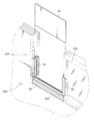
도 1는 본 발명에 따른 창문에 탈착 가능하게 설치되는 차단부재가 바람막이로 사용된 상태를 입체적으로 도시한 도면.
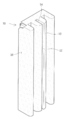
도 2는 도 1에서 도시하고 있는 제 1측면프레임의 구조를 상세하게 도시한 도면.
도 3은 도 1에서 도시하고 있는 제 2측면프레임의 구조를 상세하게 도시한 도면.
도 4는 도 1에서 도시하고 있는 바닥프레임의 구조를 상세하게 도시한 도면.
도 5는 본 발명에 따른 창문에 탈착 가능하게 설치되는 차단부재가 시선막이로 사용된 상태를 입체적으로 도시한 도면.
도 6은 본 발명에 따른 창문에 탈착 가능하게 설치되는 차단부재가 비막이로 사용된 상태를 입체적으로 도시한 도면.
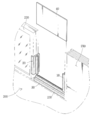
도 7 내지 도 9는 본 발명에 따른 창문에 탈착 가능하게 설치되는 차단부재에서 제 1, 2측면프레임 및 바닥프레임의 다양한 실시 형태를 도시한 도면들.
BRIEF DESCRIPTION OF THE DRAWINGS FIG. 1 is a three-dimensional view showing a state in which a blocking member detachably installed in a window according to the present invention is used as a windshield. FIG.
Fig. 2 is a detailed view showing the structure of the first side frame shown in Fig. 1. Fig.
Fig. 3 is a detailed view showing the structure of the second side frame shown in Fig. 1. Fig.
Fig. 4 is a view showing in detail the structure of the bottom frame shown in Fig. 1; Fig.
5 is a three-dimensional view showing a state in which a blocking member detachably installed on a window according to the present invention is used as a sight line.
FIG. 6 is a three-dimensional view illustrating a state in which a blocking member detachably installed in a window according to the present invention is used as a non-barrier. FIG.
7 to 9 are views showing various embodiments of the first and second side frames and the bottom frame in the blocking member detachably installed in the window according to the present invention.

이하 본 발명의 실시 예를 첨부된 도면을 참조하여 설명하면 다음과 같다. 후술 될 상세한 설명에서는 상술한 기술적 과제를 이루기 위해 본 발명에 있어 두 개의 실시 예를 대표하여 제시할 것이다. 그리고 본 발명으로 제시될 수 있는 다른 실시 예들은 본 발명의 구성에서 설명으로 대체한다.Hereinafter, embodiments of the present invention will be described with reference to the accompanying drawings. DETAILED DESCRIPTION OF THE PREFERRED EMBODIMENTS In the following detailed description, only two embodiments of the present invention will be described in order to achieve the above-mentioned technical problems. And other embodiments which may be presented by the present invention are replaced by descriptions in the constitution of the present invention.

도 1은 본 발명에 따른 창문틀을 이용한 탈부착식 차단부재가 바람막이로 사용된 상태를 입체적으로 도시한 도면이다.FIG. 1 is a three-dimensional view illustrating a state in which a removable blocking member using a window frame according to the present invention is used as a windshield. FIG.

도 1에서 도시하고 있는 바와 같이, 본 발명의 창문에 탈착 가능하게 설치되는 차단부재(100)는 외곽틀을 구성하는 제 1, 2측면프레임(10, 20)과, 바닥프레임(30) 그리고 바람막이 용도로 사용되는 차단판(40)을 포함하여 구성한다.1, a blocking member 100 detachably installed on a window of the present invention includes first and second side frames 10 and 20 constituting a frame, a bottom frame 30, and a windscreen And a blocking plate 40 used for the purpose.

상기 제 1, 2측면프레임(10, 20)과 바닥프레임(30)은 창문(200)을 구성하는 창벽틀(210)과 창문틀(220) 그리고 창문바닥틀(230)에 각각 분리 가능하게 조립되도록 구성하여 본 발명의 차단부재(100)를 다른 창문에도 얼마든지 재사용할 수 있도록 구성하게 된다.The first and second side frames 10 and 20 and the bottom frame 30 are detachably assembled to the window frame 210, the window frame 220 and the window bottom frame 230 constituting the window 200, respectively. So that the blocking member 100 of the present invention can be reused to other windows as much as possible.

첨부된 도 2는 상기 제 1측면프레임(10)의 구조를 발췌하여 도시한 도면이다. 도 2에서 도시하고 있는 바와 같이, 제 1측면프레임(10)은 창문(200)을 구성하는 창벽틀(210)에 수직으로 세워진 상태로 설치되는 수단으로서 소정의 길이를 가지며 외면은 창벽틀(210)에 끼워지고 그 내면에는 제 1측면프레임(10)의 길이 방향을 따라 가이드돌기(12)를 돌출 형성하며, 상기 가이드돌기(12) 사이로 차단막(40)의 일측이 삽입되기 위한 삽입홈(14)이 형성되도록 구성한다.FIG. 2 is a drawing illustrating the structure of the first side frame 10. FIG. As shown in FIG. 2, the first side frame 10 has a predetermined length and is installed vertically on the window frame 210 constituting the window 200. The outer side of the first side frame 10 is a window frame 210 And a guide protrusion 12 is formed on the inner surface of the guide protrusion 12 along the longitudinal direction of the first side frame 10 and an insertion groove 14 for inserting one side of the shielding film 40 between the guide protrusions 12 Is formed.

첨부된 도 3은 상기 제 2측면프레임(20)의 구조를 발췌하여 도시한 도면이다. 도 3에서 도시하고 있는 바와 같이, 제 2측면프레임(20)은 창문(200)을 구성하는 창문틀(220)에 수직으로 세워진 상태로 설치되는 수단으로서, 소정의 길이를 가지며 외면은 창문틀(220)이 끼워지기 위한 수용홈(28)이 형성되고 그 내면에는 제 2측면프레임(20)의 길이 방향을 따라 가이드돌기(22)를 돌출 형성하며, 상기 가이드돌기(22) 사이로 차단막(40)의 타측이 삽입되기 위한 삽입홈(24)이 형성되도록 구성한다.FIG. 3 is a drawing illustrating the structure of the second side frame 20. FIG. As shown in FIG. 3, the second side frame 20 is a means installed vertically on the window frame 220 constituting the window 200. The second side frame 20 has a predetermined length, A guide protrusion 22 protrudes along the longitudinal direction of the second side frame 20 on the inner surface of the receiving groove 28 and a shielding film 40 is interposed between the guide protrusions 22, And an insertion groove 24 into which the other side of the insertion hole 24 is inserted is formed.

첨부된 도 4는 상기 바닥프레임(30)의 구조를 발췌하여 도시한 도면이다. 도 4에서 도시하고 있는 바와 같이, 바닥프레임(30)은 창문(200)을 구성하는 창문바닥틀(230) 위에 수평으로 누운 상태로 설치되는 수단으로서, 소정의 길이를 가지며 상면에는 바닥프레임(30)의 길이 방향을 따라 가이드돌기(32)가 돌출 형성되며, 상기 가이드돌기(32) 사이로 차단막(40)의 하단이 삽입되기 위한 삽입홈(34)이 형성되도록 구성한다.FIG. 4 is a drawing showing the structure of the bottom frame 30. FIG. As shown in FIG. 4, the bottom frame 30 has a predetermined length and is installed horizontally on the window bottom frame 230 constituting the window 200. The bottom frame 30 has a predetermined length, A guide protrusion 32 is protruded along the longitudinal direction of the guide protrusion 32 and an insertion groove 34 for inserting the lower end of the shielding membrane 40 is formed between the guide protrusions 32.

또한 상기 바닥프레임(30)의 하면에는 상기 바닥프레임(30)의 길이 방향을 따라 레일삽입홈(38)이 함몰 형성되며, 상기 레일삽입홈(38)으로는 창문바닥틀(230)에 설치되어 있는 레일(232)이 끼워지게 된다.A rail insertion groove 38 is formed in the bottom surface of the bottom frame 30 along the longitudinal direction of the bottom frame 30 and a rail insertion groove 38 is formed in the window bottom frame 230 The rail 232 is inserted.

한편, 상기한 제 1, 2측면프레임(10, 20) 그리고 바닥프레임(30)의 외면은 소정의 탄성력을 가진 탄성패드(16, 26, 36)로 각각 코팅 처리되도록 구성한다. 상기 탄성패드(16, 26, 36)는 상기 제 1, 2측면프레임(10, 20) 및 바닥프레임(30)이 창문(200)에 설치된 상태에서 바람이나 기타 외력에 의해 흔들림이 발생할 때, 충격을 흡수하여 소음 발생을 줄여주게 된다. 또한 창문(200)을 구성하는 창벽틀(210)과 창문틀(220) 및 창문바닥틀(230)의 레일(232) 규격이 차이가 나더라도 탄성패드(16, 26, 36)가 가지는 탄성력을 이용하여 제 1, 2측면프레임(10, 20) 및 바닥프레임(30)을 창문(200)에 효과적으로 설치할 수 있도록 하기 위함이다.The outer surfaces of the first and second side frames 10 and 20 and the bottom frame 30 are coated with elastic pads 16, 26 and 36 having predetermined elasticity, respectively. When the first and second side frames 10 and 20 and the bottom frame 30 are installed on the window 200 and the swing of the first and second side frames 10 and 20 and the bottom frame 30 occurs due to wind or other external force, Thereby reducing noise generation. Even if the rail 232 of the window frame 210 constituting the window 200 is different from the rail 232 of the window frame 220 and the window bottom frame 230, the elastic force of the elastic pads 16, 26, So that the first and second side frames 10 and 20 and the bottom frame 30 can be installed effectively on the window 200. [

본 발명의 실시 예에서는 언급한 바와 같이 제 1, 2측면프레임(10, 20)과 바닥프레임(30)의 외면에 탄성패드(16, 26, 36)를 코팅 처리한 것에 대하여 대표적으로 기술하였으나, 필요에 따라서는 탄성패드(16, 26, 36)를 코팅하지 않고 상기 제 1, 2측면프레임(10, 20)과 바닥프레임(30)의 재질 자체를 탄성력을 가진 재질로 제작하여 사용할 수 있다.The elastic pads 16, 26 and 36 are coated on the outer surfaces of the first and second side frames 10 and 20 and the bottom frame 30 as described in the embodiments of the present invention, The material of the first and second side frames 10 and 20 and the bottom frame 30 may be made of a material having elasticity without using the elastic pads 16, 26 and 36 as needed.

상기 차단판(40)은 언급한 바와 같이 창문(200)에 설치된 제 1, 2측면프레임(10, 20) 그리고 바닥프레임(30) 사이에 위치한 상태에서 그 양측 및 하단을 상기 제 1, 2측면프레임(10, 20) 그리고 바닥프레임(30)의 내면에 각각 구비되어 있는 삽입홈(14, 24, 34)에 끼워지며 외부에서 불어오는 바람을 막아주는 바람막이 기능을 수행하게 되는 데, 이러한 바람막이는 음식 조리시 화기 근처에 있는 창문에 사용하면 적합할 것이다. 즉, 본 발명은 창문(200)을 열어두더라도 제 1, 2측면프레임(10, 20)과 바닥프레임(30) 그리고 상기 차단판(40)을 이용하여 바람이 실내 화기 근처로 너무 많이 불어 들어오는 것을 방지할 수 있게 된다.The blocking plate 40 is disposed between the first and second side frames 10 and 20 provided on the window 200 and the bottom frame 30 so that both sides and the bottom of the first and second side frames 10, 24 and 34 provided on the inner surfaces of the frames 10 and 20 and the inner surface of the bottom frame 30 and functions as a windshield for blocking wind blowing from the outside. It may be suitable for use in windows near firearms when cooking food. That is, even if the window 200 is opened, the present invention can prevent the wind from blowing too much near the indoor fire using the first and second side frames 10 and 20, the bottom frame 30 and the blocking plate 40 .

한편, 상기한 차단판(40)은 그 형상에 따라 바람막이 외에 다양한 기능을 구현하게 된다.Meanwhile, the blocking plate 40 has various functions in addition to the windshield according to its shape.

예를 들어, 첨부된 도 5에서와 같이 차단판(40a)의 전면에 다수개의 구멍(42)을 천공하여 바람은 통과시키되, 사람의 시선은 차단하여 개인 사생활을 보호할 수 있는 시선막이로 대체하여 사용할 수 있는 데, 이때의 시선막이용으로는 도로변 창문이나 밀착 혹은 근거리의 타인 창문과 교차하는 창문에 사용함이 바람직할 것이다.For example, as shown in FIG. 5, a plurality of holes 42 are formed in the front surface of the shield plate 40a to allow the wind to pass therethrough, In this case, it is preferable to use the line of sight at the window which is close to the road side window or the window which intersects with the near side tine window.

또한 도 6에서와 같이 차단판(40b)의 상단에 힌지(44)를 설치한 상태에서 상기 힌지(44)에 접힘판(46)을 결합 구성하여 상기 접힘판(46)이 상기 힌지(44)를 중심으로 해서 실내로 소정 각도 기울어지도록 배치하여 우천시 빗물이 실내로 들어오는 것을 방지하는 비막이로 대체하여 사용할 수 있다.
6, the folding plate 46 may be coupled to the hinge 44 so that the folding plate 46 is engaged with the hinge 44, The rainwater can be used instead of the rainwater to prevent the rainwater from entering into the room when raining.

또 한편으로, 본 발명의 차단부재를 구성하는 제 1, 2측면프레임(10, 20)과 바닥프레임(30)은 첨부된 도 7 내지 도 9에서와 같이 다양한 형태로 사용할 수 있다.On the other hand, the first and second side frames 10 and 20 and the bottom frame 30 constituting the blocking member of the present invention can be used in various forms as shown in FIGS. 7 to 9 attached hereto.

먼저, 도 7에서와 같이 창문(200)을 구성하는 창문틀(220)이 좌측에 배치되고 창벽틀(210)이 우측에 배치된 구조일 때에는 제 2측면프레임(20)을 좌측에 배치된 창문틀(220)에 설치하고, 제 1측면프레임(10)은 우측에 배치된 창벽틀(10)에 설치하며 그리고 바닥프레임(30)은 창문바닥틀(230)에 설치한 상태에서 차단막(40)을 끼워 사용토록 한다.7, when the window frame 220 constituting the window 200 is disposed on the left side and the window frame 210 is disposed on the right side, the second side frame 20 is disposed on the left side of the window The first side frame 10 is installed on the window frame 10 disposed on the right side and the bottom frame 30 is installed on the window bottom frame 230 and the blocking film 40 is installed on the window frame 230. [ .

또한 도 8, 9에서와 같이 창문(200)의 좌, 우측이 창문틀(220)일 경우에는 제 1측면프레임(10)은 사용하지 않고 바닥프레임(30) 하나를 좌측 혹은 우측의 창문틀중 어느 하나의 창문틀(210)에 배치하고, 다른 바닥프레임(30)은 창문바닥틀(230)에 설치하고, 제 2측면프레임(20)은 바닥프레임(30)이 배치되지 않은 나머지 창문틀(220)에 배치한 상태에서 차단막(40)을 끼워 사용할 수 있다.8 and 9, when the left and right sides of the window 200 are the window frame 220, the first side frame 10 is not used and one of the bottom frames 30 is used as the left or right window frame And the other side frame 20 is disposed on the other side of the window frame 210 in which the bottom frame 30 is not disposed 220, the shielding film 40 can be sandwiched and used.

즉, 본 발명의 기술은 제 1, 2측면프레임(10, 20) 및 바닥프레임(30)을 이용하여 창문(200)이 어떠한 형태를 가지더라도 이에 맞추어 용이하게 설치하여 사용할 수 있다는 데 그 기술적 특징이 있다 할 것이다.
That is, the technique of the present invention can be easily installed and used according to the shape of the window 200 using the first and second side frames 10 and 20 and the bottom frame 30, There will be.

10: 제 1측면프레임 20: 제 2측면프레임
30: 바닥프레임 100: 차단부재
200: 창문 210: 창벽틀
220: 창문틀 230: 창문바닥틀
10: first side frame 20: second side frame
30: bottom frame 100: blocking member
200: Window 210: window pane
220: Window frame 230: Window frame

Claims (2)

창문에 탈착 가능하게 설치되는 바람이나 빗물의 실내 유입을 차단하는 차단부재에 있어서,
창벽틀(210)에 수직으로 세워진 상태로 설치되며 내면에는 삽입홈(14)을 사이에 두고 가이드돌기(12)가 돌출 형성된 제 1측면프레임(10)과;
창문틀(220)에 수직으로 세워진 상태로 설치되며 외면에는 상기 창문틀(220)이 끼워지기 위한 수용홈(28)이 형성되고 그 내면에는 삽입홈(24)을 사이에 두고 가이드돌기(22)가 돌출 형성된 제 2측면프레임(20)과;
창문바닥틀(230)에 수평으로 누운 상태로 설치되며 바닥면에는 상기 창문바닥틀(230)에 설치되어 있는 레일(232)이 끼워지기 위한 레일삽입홈(38)이 형성되고 그 상면에는 삽입홈(34)을 사이에 두고 가이드돌기(32)가 돌출 형성된 바닥프레임(30) 및 ;
상기 제 1, 2측면프레임(10, 20)과 바닥프레임(30) 사이에 위치하며 그 양측 및 하단을 상기 제 1, 2측면프레임(10, 20)의 삽입홈(124, 24)과 상기 바닥프레임(30)의 삽입홈(34)에 각각 끼워넣어 조립 구성하는 차단판(40)을 포함하여 구성함을 특징으로 하는 창문에 탈착 가능하게 설치되는 차단부재.
A blocking member for blocking the entry of wind or rainwater, which is detachably installed in a window, into the room,
A first side frame 10 installed vertically on the window frame 210 and having a guide protrusion 12 protruding from the inner surface thereof with an insertion groove 14 therebetween;
A receiving groove 28 for receiving the window frame 220 is formed on the outer surface of the window frame 220 and a guide protrusion 22 is formed on the inner surface of the receiving groove 28 with the insertion groove 24 therebetween. A second side frame 20 protruding from the second side frame 20;
A rail insertion groove 38 for fitting the rail 232 installed on the window bottom frame 230 is formed on the bottom surface of the window frame 230, A bottom frame 30 having a guide protrusion 32 protruding therebetween;
The first and second side frames 10 and 20 are positioned between the first and second side frames 10 and 20 and the bottom frame 30 and have both sides thereof inserted into the insertion grooves 124 and 24 of the first and second side frames 10 and 20, And a shielding plate (40) sandwiched and assembled into the insertion groove (34) of the frame (30).
제 1항에 있어서,
상기 제 1, 2측면프레임(10, 20)과 상기 바닥프레임(30)의 외면은 탄성력을 가진 탄성패드(16, 26, 36)가 각각 코팅 처리됨을 특징으로 하는 창문에 탈착 가능하게 설치되는 차단부재.

The method according to claim 1,
Wherein elastic pads (16, 26, 36) having an elastic force are coated on outer surfaces of the first and second side frames (10, 20) and the bottom frame (30) absence.

KR1020140083507A 2014-07-04 2014-07-04 The sunlight shutter Abandoned KR20160004695A (en)

Priority Applications (1)

Application Number Priority Date Filing Date Title
KR1020140083507A KR20160004695A (en) 2014-07-04 2014-07-04 The sunlight shutter

Applications Claiming Priority (1)

Application Number Priority Date Filing Date Title
KR1020140083507A KR20160004695A (en) 2014-07-04 2014-07-04 The sunlight shutter

Publications (1)

Publication Number Publication Date
KR20160004695A true KR20160004695A (en) 2016-01-13

Family

ID=55172602

Family Applications (1)

Application Number Title Priority Date Filing Date
KR1020140083507A Abandoned KR20160004695A (en) 2014-07-04 2014-07-04 The sunlight shutter

Country Status (1)

Country Link
KR (1) KR20160004695A (en)

Cited By (3)

* Cited by examiner, † Cited by third party
Publication number Priority date Publication date Assignee Title
KR20200015164A (en) * 2018-08-03 2020-02-12 장초아 Rainwater shutoff material for windows
KR102755751B1 (en) * 2023-10-24 2025-01-21 디에스산업개발주식회사 Window well cover to prevent water infiltration
KR102850776B1 (en) * 2025-04-24 2025-08-25 류정환 Flashing device for railing

Cited By (3)

* Cited by examiner, † Cited by third party
Publication number Priority date Publication date Assignee Title
KR20200015164A (en) * 2018-08-03 2020-02-12 장초아 Rainwater shutoff material for windows
KR102755751B1 (en) * 2023-10-24 2025-01-21 디에스산업개발주식회사 Window well cover to prevent water infiltration
KR102850776B1 (en) * 2025-04-24 2025-08-25 류정환 Flashing device for railing

Similar Documents

Publication Publication Date Title
KR200474774Y1 (en) The Corner connector for anti-chassis frame
KR101256039B1 (en) Screen-louver assembly conformed in single
KR20160004695A (en) The sunlight shutter
CN205663118U (en) Window system for installation in sloped surfaces of buildings
WO2009084878A3 (en) Double window having horizontal cross-ventilation function
KR101581201B1 (en) a dual layer screen window frames system
KR102265493B1 (en) Smart insect net using double panel with zigzag hole
KR20130005039U (en) awning
CN101592008B (en) Door and window frame of building outside door and window sunshade integrative system
KR200453279Y1 (en) Windows for Ventilation Systems
KR20100032078A (en) Mosquito net device
CN204680929U (en) A kind of dust guard and use door and the transformer station box of this dust guard
JP2013057166A (en) Screen door with panel
CN205297235U (en) Dustproof louver
KR101795578B1 (en) Mosquito-net for door having screen
KR200474773Y1 (en) The Corner connector for anti-chassis frame
KR101552545B1 (en) Water spots prevention screen for outer wall
JP2010222893A (en) Blind net
KR20090089627A (en) Window
KR20170055191A (en) Shielding structure of sliding door sash frame drain hole for drainage
KR20200121226A (en) A dustproof net frame with anti-shake function and coupling structure that combines dustproof net in frame
KR20130092021A (en) Airtight device for window crack
CN204645972U (en) With the floor spring door system endured in reinforcement
JP6592295B2 (en) Opening and closing body
JP3166824U (en) Shoji with louver

Legal Events

Date Code Title Description
A201 Request for examination
PA0109 Patent application

Patent event code: PA01091R01D

Comment text: Patent Application

Patent event date: 20140704

PA0201 Request for examination
E701 Decision to grant or registration of patent right
PE0701 Decision of registration

Patent event code: PE07011S01D

Comment text: Decision to Grant Registration

Patent event date: 20150825

PG1501 Laying open of application
NORF Unpaid initial registration fee
PC1904 Unpaid initial registration fee