KR20150142035A - Workpiece having exfoliating characteristics - Google Patents
Workpiece having exfoliating characteristics Download PDFInfo
- Publication number
- KR20150142035A KR20150142035A KR1020157032339A KR20157032339A KR20150142035A KR 20150142035 A KR20150142035 A KR 20150142035A KR 1020157032339 A KR1020157032339 A KR 1020157032339A KR 20157032339 A KR20157032339 A KR 20157032339A KR 20150142035 A KR20150142035 A KR 20150142035A
- Authority
- KR
- South Korea
- Prior art keywords
- abrasive
- abrasive elements
- flexible member
- section
- damping device
- Prior art date
Links
Images


Classifications
-
- A—HUMAN NECESSITIES
- A61—MEDICAL OR VETERINARY SCIENCE; HYGIENE
- A61B—DIAGNOSIS; SURGERY; IDENTIFICATION
- A61B17/00—Surgical instruments, devices or methods, e.g. tourniquets
- A61B17/54—Chiropodists' instruments, e.g. pedicure
-
- A—HUMAN NECESSITIES
- A61—MEDICAL OR VETERINARY SCIENCE; HYGIENE
- A61B—DIAGNOSIS; SURGERY; IDENTIFICATION
- A61B17/00—Surgical instruments, devices or methods, e.g. tourniquets
- A61B2017/00367—Details of actuation of instruments, e.g. relations between pushing buttons, or the like, and activation of the tool, working tip, or the like
- A61B2017/00398—Details of actuation of instruments, e.g. relations between pushing buttons, or the like, and activation of the tool, working tip, or the like using powered actuators, e.g. stepper motors, solenoids
-
- A—HUMAN NECESSITIES
- A61—MEDICAL OR VETERINARY SCIENCE; HYGIENE
- A61B—DIAGNOSIS; SURGERY; IDENTIFICATION
- A61B17/00—Surgical instruments, devices or methods, e.g. tourniquets
- A61B17/32—Surgical cutting instruments
- A61B2017/320004—Surgical cutting instruments abrasive
Landscapes
- Health & Medical Sciences (AREA)
- Life Sciences & Earth Sciences (AREA)
- Surgery (AREA)
- Molecular Biology (AREA)
- Engineering & Computer Science (AREA)
- Biomedical Technology (AREA)
- Heart & Thoracic Surgery (AREA)
- Medical Informatics (AREA)
- Nuclear Medicine, Radiotherapy & Molecular Imaging (AREA)
- Animal Behavior & Ethology (AREA)
- General Health & Medical Sciences (AREA)
- Public Health (AREA)
- Veterinary Medicine (AREA)
- Finish Polishing, Edge Sharpening, And Grinding By Specific Grinding Devices (AREA)
- Percussion Or Vibration Massage (AREA)
- Surgical Instruments (AREA)
Abstract
개인 관리 기구와 함께 사용되기 위한 연마 표면을 갖는 박리 헤드 형태의 작업편이 개시된다. 개인 관리 기구는 피부 관리 제제의 앞선 적용을 가지면서 또는 갖지 않으면서 대상의 표피의 향상된 스무딩 (smoothing) 및 박리를 제공하기 위해 박리 헤드를 진동시키도록 구성된다. 박리 헤드는 환자의 손이나 발에 형성된 굳은살이나 못과 같은 거친 피부 상태를 처리하기 위해 사용될 수도 있다. 댐핑 디바이스를 갖는 이러한 작업편의 예들이 또한 제공된다. 댐핑 디바이스는 작업편의 잠재적인 원하지 않는 운동을 댐핑하고, 근공진 개인 관리 기구의 진동 모터 시스템의 튜닝을 허용한다.A workpiece in the form of a peel head having a polishing surface for use with a personal care tool is disclosed. Personal care devices are configured to vibrate the peel head to provide enhanced smoothing and peeling of the skin of the subject with or without prior application of the skin care formulation. The peeling head may be used to treat rough skin conditions such as hard flesh or nails formed on the patient's hands or feet. Examples of such workpieces with damping devices are also provided. The damping device damps potential undesired movements of the workpiece and allows tuning of the vibration motor system of the muscle resonance personal care device.
Description
본 기술분야의 통상의 기술자에게 잘 알려진 바와 같이, 시간이 경과함에 따라 손이나 발이 단단하거나 거친 다양한 표면과 자주 반복적으로 접촉함으로 인해 손바닥이나 발바닥의 표피가 적어도 부분적으로 각질화되는 때에 일반적으로 손의 손바닥이나 발의 발바닥에 두꺼운 굳은살이나 못이 형성된다. 예를 들어, 손의 굳은살은 공구나 스포츠 장비와 같은 손에 압력을 가하는 물체의 정기적인 핸들링에 의해 종종 야기된다. 발의 굳은살과 못은 꼭 끼는 신발, 굽이 높은 신발, 느슨한 신발 및 바닥이 얇은 신발과 같은 신발로부터의 압력에 의해 종종 야기된다. 접촉으로 인한 반복적인 압력은 피부가 죽게 하고 단단한 보호 표면을 형성하게 한다.As is well known to those of ordinary skill in the art, when the palms or soles of the soles are at least partially keratinized by the frequent repeated contact of the hands or feet with various hard or rough surfaces over time, as generally known to those of ordinary skill in the art, A thick solid flesh or nail is formed on the soles or feet of the feet. For example, the hard flesh of a hand is often caused by the regular handling of objects that exert pressure on the hands, such as tools or sports equipment. Foot flesh and nails are often caused by pressure from shoes such as tight-fitting shoes, high-heeled shoes, loose shoes and thin-bottomed shoes. Repeated pressure from contact causes the skin to die and form a hard protective surface.
굳은살과 못은 불편함을 야기할 수 있고, 또한 고통스러울 수 있다. 더욱이, 굳은살이나 못은 예컨대 건조하거나 추운 날씨로 인해 갈라져서, 표피 아래의 진피가 손상될 수 있다. 그러므로, 손의 손바닥이나 발의 발바닥으로부터 그러한 굳은살이나 못을 정기적으로 제거하는 것이 종종 필요하다. 손이나 발로부터의 굳은살이나 못의 그러한 제거는 통상적으로 "페디큐어" 라고 불린다.Hard flesh and nails can cause discomfort and can also be painful. Moreover, hard flesh or nails may be split by dry or cold weather, for example, and the dermis beneath the epidermis may be damaged. Therefore, it is often necessary to periodically remove such hard flesh or nails from the palms of the hands or the soles of the feet. Such removal of hard flesh or nails from the hands or feet is commonly referred to as "pedicure".
페디큐어 동안에, 굳은살과 건조하고 각질이 일어나는 피부는 발의 저부로부터 벗겨내거나 긁어내어진다. 전형적으로, 발을 따뜻한 욕조에 담그고, 그리고/또는 피부를 부드럽게 하기 위해 국소 제제 (topical formula) 가 적용된다. 일단 따뜻한 물 및/또는 국소 제제가 발의 피부를 부드럽게 하고 나면, 발의 저부는 내구성의 플라스틱 핸들에 부착된 연마 샌딩 (abrasive sanding) 패드로 구성된 페디큐어 샌더, 굳은살용 줄 (callus rasp) 또는 부석 (pumice stone) 중의 하나로 손으로 스크러빙된다. 부가적으로, 일부 기술자는 발로부터 두껍고 단단한 굳은살을 얇게 잘라내는 융기된 면도날을 갖는 스테인리스강 헤드로 구성된 못과 굳은살용 플레인 (corn and callus plane) 을 사용할 것이다.During the pedicure, the hard flesh and the dry, keratinized skin are peeled off or scraped from the bottom of the foot. Typically, a topical formula is applied to soak the feet in a warm bath and / or to soften the skin. Once the warm water and / or topical agent softens the skin of the foot, the bottom of the foot is covered with a pedicure sander, a callus rasp or a pumice stone consisting of an abrasive sanding pad attached to a durable plastic handle ) Is scrubbed by hand. Additionally, some engineers will use a nail and a corn and callus plane consisting of a stainless steel head with raised razor blade to cut thin, hard, hard flesh from the foot.
굳은살 제거를 위한 이러한 종래 방법들 및 장치들은 시간 소모적이고, 힘들고, 비효율적이며, 종종 고통스럽다. 또한, 종래의 기구의 몇몇은 위험하다. 특히, 굳은살용 플레인은 부적절하게 사용되면 심각한 상처를 야기할 수도 있다. 따라서, 수동 프로세스의 위험과 해로운 효과를 감소시키기 위해, 발과 손으로부터 피부 결함을 제거하는 프로세스를 자동화하려는 시도가 있었다. 예컨대, 손과 발을 그루밍 (grooming) 하기 위해 사포형 접촉 표면을 갖는 여러 전동식 회전 디바이스가 고안되었고, 그러한 디바이스 중 하나가 상표명 "Pedi-Smooth" 로 판매되고 있다.These conventional methods and devices for removing solid flesh are time consuming, laborious, inefficient, and often painful. Also, some of the conventional instruments are dangerous. In particular, hardened flesh planes may cause serious injury if used improperly. Accordingly, there has been an attempt to automate the process of removing skin imperfections from the feet and hands to reduce the risk and harmful effects of the manual process. For example, several electric rotating devices having a sandblasted contact surface have been devised for grooming hands and feet, and one such device is sold under the trade name "Pedi-Smooth ".
이 내용은 상세한 설명에서 더 후술하는 간단한 형태의 개념들의 선택을 소개하기 위해 제공된다. 이 내용은 청구되는 주제의 중요한 특징을 확인하려는 것이 아니며, 청구되는 주제의 범위 결정을 돕는 것으로서 사용하려는 것이 아니다.This description is provided to introduce the selection of concepts in the form of a brief description which will be further described in the detailed description. This is not intended to identify important features of the claimed subject matter, nor is it intended to be used as an aid in determining the scope of the claimed subject matter.
본 개시의 양태들에 따르면, 작업편이 제공된다. 작업편은 구동 시스템을 갖는 개인 관리 기구 (personal care appliance) 와 함께 사용될 수 있다. 작업편은 구동 시스템에 작동식으로 커플링되도록 구성된 가동 베이스부, 및 이동하는 상기 베이스부에 장착된 디스크 플레이트를 포함한다. 디스크 플레이트는 일부 실시형태들에서 표면에 배치된 연마재 (abrasive) 를 갖는 외향 접촉 표면을 포함한다. 연마재는 일부 실시형태들에서 표피의 부분적으로 각질화된 (keratinized) 영역을, 그와 접촉하게 위치되는 때에 박리하도록 구성된다.According to aspects of the present disclosure, a work piece is provided. The work piece may be used with a personal care appliance having a drive system. The workpiece includes a movable base portion configured to be operatively coupled to the drive system, and a disk plate mounted to the moving base portion. The disc plate includes an outwardly contacting surface with an abrasive disposed on the surface in some embodiments. The abrasive is configured to, in some embodiments, delaminate a partially keratinized region of the epidermis when placed in contact therewith.
일부 실시형태들에서, 연마재는 복수의 연마 요소들을 포함한다. 일부 실시형태들에서 하나 이상의 연마 요소들은 임의의 조합으로 다음의 특징들 중의 하나 이상을 특징으로 할 수 있다: 하나 이상의 연마 요소들이 접촉 표면으로부터 약 0.003 인치 (0.0762 밀리미터) 내지 약 0.008 인치 (0.203 밀리미터) 의 높이로 외향 연장되고; 복수의 연마 요소들 중의 하나 이상의 연마 요소들이 접촉 표면과 일반적으로 평행한 평면 내에 놓인 일반적으로 평평한 상부 표면을 포함하고; 복수의 연마 요소들 중의 하나 이상의 연마 요소들이 상부 표면과 하나 이상의 절삭 에지들을 형성하는 내측으로 테이퍼진 (tapering) 측벽들을 포함하고; 접촉 표면에 인접하는 연마 요소의 상부 표면의 단면적과 베이스의 단면적의 백분율로서의 비가 일부 실시형태들에서 30 % 내지 60 % 이고 다른 실시형태들에서 48 % 내지 52 % 이고; 하나 이상의 연마 요소들이 접촉 표면에 인접하는 베이스 섹션, 및 상기 베이스 섹션에 인접하는 상부 섹션을 포함하고, 상기 상부 섹션은, 절삭 에지들에서 상기 상부 섹션에 인접하고 또한 상기 상부 섹션과의 사이에 90 도 이하의 각도를 형성하는 측벽들을 갖고; 연마 요소들 중의 하나 이상에 있어서 상기 베이스 섹션과 상기 상부 섹션 사이의 전이부가 상기 상부 표면으로부터 약 0.0005 인치 (0.0127 밀리미터) 내지 약 0.002 인치 (0.0508 밀리미터) 이다.In some embodiments, the abrasive comprises a plurality of abrasive elements. In some embodiments, the one or more abrasive elements may be characterized in any combination by one or more of the following features: one or more abrasive elements are about 0.003 inches (0.0762 millimeters) to about 0.008 inches (0.203 millimeters ); ≪ / RTI > Wherein at least one of the plurality of abrasive elements comprises a generally flat upper surface lying within a plane generally parallel to the contact surface; Wherein one or more abrasive elements of the plurality of abrasive elements include inwardly tapering sidewalls defining an upper surface and one or more cutting edges; The ratio of the cross-sectional area of the upper surface of the abrasive element adjacent the contact surface to the percentage of the cross-sectional area of the base is between 30% and 60% in some embodiments and between 48% and 52% in other embodiments; Wherein the at least one abrasive element comprises a base section adjacent the contact surface and an upper section adjacent to the base section, the upper section being adjacent to the upper section at cutting edges and also between the upper section Having side walls forming an angle less than or equal to < RTI ID = 0.0 > In at least one of the abrasive elements, the transition between the base section and the upper section is about 0.0005 inches (0.0127 millimeters) to about 0.002 inches (0.0508 millimeters) from the upper surface.
부가적으로 또는 대안적으로, 접촉 표면은 일부 실시형태들에서 연마재가 없는 중앙 영역을 더 포함한다.Additionally or alternatively, the contact surface further comprises a central region free of abrasive material in some embodiments.
본 개시의 일부 실시형태들에 따르면, 작업편은 댐핑 디바이스를 부가적으로 또는 대안적으로 포함할 수도 있다. 댐핑 디바이스는 가동 베이스부에 의해 지탱될 (carried) 수 있고, 구동 시스템에 의해 진동되는 때에 작업편의 운동을 댐핑하도록 구성될 수 있다. 일부 실시형태들에서, 댐핑 디바이스는 디스크 플레이트와는 별개이다. 이러한 실시형태들 중의 일부에 있어서, 가동 베이스부는 내부 캐비티를 규정하고, 댐핑 디바이스는 내부 캐비티 내에 배치된다. 일 실시형태에서, 가동 베이스부는 내부 캐비티 내로 연장되는 중앙 보스를 포함하고, 중앙 보스에 댐핑 디바이스가 장착된다.According to some embodiments of the present disclosure, the workpiece may additionally or alternatively include a damping device. The damping device may be carried by the movable base portion and configured to damp the motion of the workpiece when vibrated by the drive system. In some embodiments, the damping device is separate from the disc plate. In some of these embodiments, the movable base portion defines an inner cavity, and the damping device is disposed within the inner cavity. In one embodiment, the movable base portion includes a central boss extending into the inner cavity, and a damping device is mounted to the central boss.
본 개시의 일부 실시형태들에 따르면 작업편은 작업편의 운동을 댐핑하기 위한 그리고 구동 시스템을 튜닝하기 위한 수단을 부가적으로 또는 대안적으로 포함할 수도 있고, 상기 수단은 가동 베이스부에 의해 지탱되고 디스크 플레이트로부터 분리되어 있다.According to some embodiments of the present disclosure, the workpiece may additionally or alternatively include means for damping the workpiece motion and for tuning the drive system, the means being supported by the movable base portion And is separated from the disc plate.
본 개시의 일부 실시형태들에서, 댐핑 디바이스 또는 댐핑 수단은 가요성 부재를 포함한다. 가요성 부재는 임의의 조합으로 다음의 특징들 중의 하나 이상을 포함하거나 특징으로 할 수 있다: 가요성 부재가 10 Shore A 내지 100 Shore A 의 경도 값을 갖고; 가요성 부재가 10 Shore A 내지 100 Shore A 의 경도 값을 갖는 엘라스토머 재료를 포함하고; 가요성 부재가 중앙 섹션 및 상기 중앙 섹션으로부터 연장되는 복수의 베인들 (vanes) 을 포함하고; 가요성 부재가 시트를 포함하고, 상기 시트로부터 복수의 이격된 돌기부들이 외향 연장되고; 가요성 부재가 X 축 및 Y 축을 따라 대칭이다.In some embodiments of the present disclosure, the damping device or damping means comprises a flexible member. The flexible member may comprise or be characterized in any combination of one or more of the following features: the flexible member has a hardness value of from 10 Shore A to 100 Shore A; Wherein the flexible member comprises an elastomeric material having a hardness value from 10 Shore A to 100 Shore A; The flexible member comprising a central section and a plurality of vanes extending from the central section; Wherein the flexible member comprises a sheet and a plurality of spaced apart protrusions extend outwardly from the sheet; The flexible members are symmetrical along the X and Y axes.
본 개시의 다른 양태에 따르면, 박리 시스템이 제공된다. 박리 시스템은, 구동 샤프트를 진동시키도록 구성된 구동 모터를 갖는 기구; 및 상기 기구에 선택적으로 부착된 브러시없는 박리 헤드를 포함한다. 브러시없는 박리 헤드는 일부 실시형태들에서 구동 모터에 응답하여 구동 샤프트로 진동하도록 구동 샤프트에 작동식으로 커플링된 가동부를 포함한다. 가동부는 복수의 연마 요소들을 표면에 갖는 일반적으로 평평한 외향 접촉 표면을 포함한다. 각 연마 요소는 표피와 접촉하도록 위치되는 때에 상기 표피를 박리하도록 구성된다. 일부 실시형태들에서, 각 연마 요소는 표피의 부분적으로 각질화된 영역을, 그와 접촉하게 위치되는 때에 박리하도록 구성된다.According to another aspect of the present disclosure, a peeling system is provided. The peeling system includes: a mechanism having a drive motor configured to vibrate the drive shaft; And a brushless peeling head selectively attached to the mechanism. The brushless stripping head includes, in some embodiments, a moveable portion operatively coupled to the drive shaft to vibrate with the drive shaft in response to the drive motor. The moving part includes a generally flat outwardly contacting surface having a plurality of abrasive elements on the surface. Each abrasive element is configured to ablate the epidermis when positioned to contact the epidermis. In some embodiments, each abrasive element is configured to exfoliate a partially cornified area of the epidermis when placed in contact therewith.
일부 실시형태들에서, 하나 이상의 연마 요소들은 임의의 조합으로 다음의 특징들 중의 하나 이상을 특징으로 할 수 있다: 연마 요소들 중의 하나 이상이 표면으로부터 0.003 인치 (0.0762 밀리미터) 내지 약 0.008 인치 (0.203 밀리미터) 의 높이로 외향 연장되고; 복수의 연마 요소들 중의 하나 이상이 외향 접촉 표면과 일반적으로 평행한 평면 내에 놓인 일반적으로 평평한 상부 표면을 포함하고; 접촉 표면에 인접하는 연마 요소의 상부 표면의 단면적과 베이스에서의 단면적의 백분율로서의 비가 30 % 내지 60 % 이다.In some embodiments, one or more of the abrasive elements may be characterized in any combination of one or more of the following features: one or more of the abrasive elements are formed from 0.003 inches (0.0762 mm) to about 0.008 inches Lt; / RTI >millimeters); Wherein at least one of the plurality of abrasive elements comprises a generally flat upper surface lying within a plane generally parallel to the outwardly contacting surface; The ratio of the cross-sectional area of the upper surface of the abrasive element adjacent to the contact surface to the percentage of the cross-sectional area at the base is 30% to 60%.
부가적으로 또는 대안적으로, 구동 모터 및 구동 샤프트는 일부 실시형태들에서 약 100-190 Hz 의 진동수 및 약 12-18 도의 진폭으로 가동부를 진동시키도록 구성된다. 일부 실시형태들에서, 구동 모터 및 구동 샤프트는 약 168-178 Hz 의 진동수 및 약 12-18 도의 진폭으로 가동부를 진동시키도록 구성된다.Additionally or alternatively, the drive motor and drive shaft are configured to oscillate the moveable portion in some embodiments with a frequency of about 100-190 Hz and an amplitude of about 12-18 degrees. In some embodiments, the drive motor and drive shaft are configured to oscillate the movements at a frequency of about 168-178 Hz and an amplitude of about 12-18 degrees.
본 개시의 다른 양태에 따르면, 대상 (subject) 의 표피로부터 피부를 박리하기 위한 방법이 제공된다. 상기 방법은, 모터식 (motorized) 구동 시스템을 통해, 연마 요소들을 표면에 갖는 외측 표면을 구비하는 박리 헤드를 진동시키는 단계를 포함한다. 연마 요소들은 대상의 표피의 부분적으로 각질화된 영역들을 박리하도록 구성된다. 상기 방법은 대상의 표피의 일부에 대해 연마 요소들을 적용하는 (applying) 단계를 또한 포함한다. 일부 실시형태들에서, 상기 방법은, 연마 요소들이 대상의 표피에 대해 적용된 채로, 대상의 표피의 섹션들 위에서 박리 헤드를 이동시키는 단계를 또한 포함한다.According to another aspect of the present disclosure, a method is provided for peeling skin from the epidermis of a subject. The method includes vibrating a peeling head having an outer surface with abrasive elements on the surface, via a motorized drive system. The abrasive elements are configured to exfoliate the partially keratinized areas of the epidermis of the subject. The method also includes applying abrasive elements to a portion of the epidermis of the subject. In some embodiments, the method also includes moving the peeling head over sections of the epidermis of the subject, with the polishing elements applied to the epidermis of the subject.
일부 실시형태들에서, 박리 헤드를 진동시키는 단계는, 100-190 ㎐ 의 선택된 진동수에서 12-18 도의 선택된 각도를 통해 박리 헤드를 진동시키는 것을 포함한다. 다른 실시형태들에서, 선택된 진동수의 범위가 168-178 Hz 이다.In some embodiments, vibrating the peeling head includes vibrating the peeling head through a selected angle of 12-18 degrees at a selected frequency of 100-190 Hz. In other embodiments, the range of selected frequencies is 168-178 Hz.
부가적으로 또는 대안적으로, 연마 요소들을 적용하는 단계는 일부 실시형태들에서 대상의 표피의 부분적으로 각질화된 영역에 대해 연마 요소들을 적용하는 것을 포함한다.Additionally or alternatively, applying the abrasive elements comprises applying abrasive elements to the partially cornified area of the epidermis of the subject in some embodiments.
본 개시의 다른 양태에 따르면, 작업편이 제공된다. 작업편은, 상부 섹션 및 저부 섹션을 구비하는 보디로서, 상기 저부 섹션은 진동 구동 모터에 커플링되도록 구성되는, 상기 보디; 연마재를 포함하는 트리트먼트 어플리케이터 (treatment applicator) 로서, 일부 실시형태들에서 박리 디스크인 상기 트리트먼트 어플리케이터; 및 상기 보디에 의해 지탱되고 상기 진동 구동 모터에 의해 진동되는 때에 상기 보디의 운동을 댐핑하도록 구성되는 댐핑 디바이스를 포함한다. 댐핑 디바이스는 트리트먼트 어플리케이터와는 별개이다. 일부 실시형태들에서, 연마재는 표피의 부분적으로 각질화된 영역을, 그와 접촉하게 위치되는 때에 박리하도록 구성된다.According to another aspect of the present disclosure, a workpiece is provided. Wherein the workpiece is a body having an upper section and a bottom section, the bottom section being configured to be coupled to a vibration drive motor; A treatment applicator comprising an abrasive, said treatment applicator being, in some embodiments, a peel disc; And a damping device carried by the body and configured to damp the motion of the body when vibrated by the vibration drive motor. The damping device is separate from the treatment applicator. In some embodiments, the abrasive is configured to exfoliate the partially cornified region of the epidermis when placed in contact therewith.
일부 실시형태들에서, 연마재는 복수의 연마 요소들을 포함한다. 하나 이상의 연마 요소들은 일부 실시형태들에서 임의의 조합으로 다음의 특징들 중의 하나 이상을 특징으로 할 수 있다: 복수의 연마 요소들 중의 하나 이상의 연마 요소들이 접촉 표면으로부터 0.003 인치 (0.0762 밀리미터) 내지 약 0.008 인치 (0.203 밀리미터) 의 높이로 외향 연장되고; 복수의 연마 요소들 중의 하나 이상의 연마 요소들이, 상기 접촉 표면과 일반적으로 평행한 평면 내에 놓인 일반적으로 평평한 상부 표면, 및 상기 상부 표면과 하나 이상의 절삭 에지들을 형성하는 내측으로 테이퍼진 측벽들을 포함하고; 접촉 표면에 인접하는 연마 요소의 상부 표면의 단면적과 베이스의 단면적의 백분율로서의 비가 30 % 내지 60 % 이다.In some embodiments, the abrasive comprises a plurality of abrasive elements. The one or more abrasive elements may be characterized in some combinations in any combination of one or more of the following features: one or more of the abrasive elements of the plurality of abrasive elements are spaced from the contact surface by about 0.003 inches (0.0762 millimeters) Extended outward to a height of 0.008 inch (0.203 mm); One or more abrasive elements of the plurality of abrasive elements include generally planar upper surfaces lying within a plane generally parallel to the contact surface and inwardly tapering sidewalls defining the upper surface and one or more cutting edges; The ratio of the cross-sectional area of the upper surface of the abrasive element adjacent to the contact surface to the percentage of the cross-sectional area of the base is 30% to 60%.
부가적으로 또는 대안적으로, 보디는 일부 실시형태들에서 상부 섹션과 저부 섹션 사이에 배치된 내부 캐비티를 규정한다. 댐핑 디바이스는 내부 캐비티 내에 배치된다. 일부 부가적인 실시형태들에서, 보디는 내부 캐비티 내로 연장되는 중앙 보스를 포함하고, 중앙 보스에 댐핑 디바이스가 장착된다.Additionally or alternatively, the body defines an internal cavity disposed between the upper section and the bottom section in some embodiments. The damping device is disposed in the inner cavity. In some additional embodiments, the body includes a central boss extending into the inner cavity, and a damping device is mounted on the central boss.
본 개시의 일부 실시형태들에서, 댐핑 디바이스는 가요성 부재를 포함한다. 가요성 부재는 임의의 조합으로 다음의 특징들 중의 하나 이상을 포함하거나 특징으로 할 수 있다: 가요성 부재가 10 Shore A 내지 100 Shore A 의 경도 값을 갖고; 가요성 부재가 10 Shore A 내지 100 Shore A 의 경도 값을 갖는 엘라스토머 재료를 포함하고; 가요성 부재가 중앙 섹션 및 상기 중앙 섹션으로부터 연장되는 복수의 베인들을 포함하고; 가요성 부재가 시트를 포함하고, 상기 시트로부터 복수의 이격된 돌기부들이 외향 연장되고; 가요성 부재가 X 축 및 Y 축을 따라 대칭이다.In some embodiments of the present disclosure, the damping device includes a flexible member. The flexible member may comprise or be characterized in any combination of one or more of the following features: the flexible member has a hardness value of from 10 Shore A to 100 Shore A; Wherein the flexible member comprises an elastomeric material having a hardness value from 10 Shore A to 100 Shore A; The flexible member includes a central section and a plurality of vanes extending from the central section; Wherein the flexible member comprises a sheet and a plurality of spaced apart protrusions extend outwardly from the sheet; The flexible members are symmetrical along the X and Y axes.
본 개시의 또 다른 양태에 따르면, 동력식 (powered) 피부 관리 디바이스가 제공된다. 상기 디바이스는, 진동 모터 시스템을 갖는 동력식 핸들; 및 상기 동력식 핸들에 장착되고 공진 또는 근공진 (near resonance) 으로 상기 진동 모터 시스템에 의해 이동되도록 구성된 작업편을 포함한다. 일부 실시형태들에서, 작업편은, 상부 섹션 및 저부 섹션을 갖는 보디로서, 상기 저부 섹션은 진동 모터 시스템에 커플링되도록 구성된, 상기 보디; 상기 상부 섹션에 배치되고 연마재를 포함하는 트리트먼트 어플리케이터; 및 상기 작업편의 운동을 댐핑하기 위한 그리고 상기 진동 모터 시스템을 튜닝하기 위한 수단을 포함한다. 일부 실시형태들에서, 상기 수단은 상기 보디에 의해 지탱되고 상기 트리트먼트 어플리케이터와는 별개이다.In accordance with yet another aspect of the present disclosure, a powered skin care device is provided. The device comprising: a powered handle having a vibrating motor system; And a workpiece mounted to the powered handle and configured to be moved by the vibration motor system in resonance or near resonance. In some embodiments, the workpiece is a body having an upper section and a bottom section, the bottom section being configured to be coupled to the vibration motor system; A treatment applicator disposed in the upper section and including an abrasive; And means for damping the motion of the workpiece and for tuning the vibration motor system. In some embodiments, the means is carried by the body and is separate from the treatment applicator.
본 개시의 일부 실시형태들에서, 댐핑 수단은 가요성 부재를 포함한다. 가요성 부재는 임의의 조합으로 다음의 특징들 중의 하나 이상을 포함하거나 특징으로 할 수 있다: 가요성 부재가 10 Shore A 내지 100 Shore A 의 경도 값을 갖고; 가요성 부재가 10 Shore A 내지 100 Shore A 의 경도 값을 갖는 엘라스토머 재료를 포함하고; 가요성 부재가 중앙 섹션 및 상기 중앙 섹션으로부터 연장되는 복수의 베인들을 포함하고; 가요성 부재가 시트를 포함하고, 상기 시트로부터 복수의 이격된 돌기부들이 돌출하고; 가요성 부재가 X 축 및 Y 축을 따라 대칭이다.In some embodiments of the present disclosure, the damping means comprises a flexible member. The flexible member may comprise or be characterized in any combination of one or more of the following features: the flexible member has a hardness value of from 10 Shore A to 100 Shore A; Wherein the flexible member comprises an elastomeric material having a hardness value from 10 Shore A to 100 Shore A; The flexible member includes a central section and a plurality of vanes extending from the central section; Wherein the flexible member comprises a sheet, and a plurality of spaced apart projections protrude from the sheet; The flexible members are symmetrical along the X and Y axes.
부가적으로 또는 대안적으로, 보디는 일부 실시형태들에서 상부 섹션과 저부 섹션 사이에 배치되는 내부 캐비티, 및 내부 캐비티 내로 연장되는 중앙 보스를 규정한다. 일부 실시형태들에서, 상기 수단은 내부 캐비니 내에 배치되고 중앙 보스에 장착된다.Additionally or alternatively, the body defines an inner cavity disposed between the upper section and the bottom section in some embodiments, and a central boss extending into the inner cavity. In some embodiments, the means is disposed within the inner cabin and mounted to the central boss.
개시된 주제의 상기 양태들 및 부수적인 이점들의 다수가, 첨부 도면과 함께 이하의 상세한 설명을 참조함으로써 더 잘 이해될 것이므로 더 용이하게 이해될 것이다.BRIEF DESCRIPTION OF THE DRAWINGS The foregoing aspects of the disclosed subject matter and many of the attendant advantages will be more readily appreciated as the same becomes better understood by reference to the following detailed description when taken in conjunction with the accompanying drawings, in which: FIG.
도 1 은 본 발명의 양태들에 따른, 박리 헤드와 같은 작업편의 일례의 사시도이다.
도 2 는 도 1 의 박리 헤드의 분해도이다.
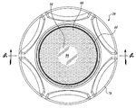
도 3 은 도 1 의 박리 헤드와 같은 박리 헤드의 상면도이다.
도 4 는 구동 모터 시스템의 부품들에 연결되도록 되어 있는 도 1 의 박리 헤드의 단면도이다.
도 5 는 본 발명의 양태들에 따라 표면에 연마 요소들을 갖는 표면의 일례의 부분 측면도이다.
도 6 은 본 발명의 양태들에 따라 표면에 연마 요소들을 갖는 표면의 다른 예의 부분 측면도이다.
도 7 은 본 발명의 양태들에 따라 표면에 연마 요소들을 갖는 표면의 다른 예의 부분 측면도이다.
도 8 은 도 1 의 박리 헤드가 장착된 개인 관리 기구의 일례의 사시도이다.
도 9 는 박리 헤드가 분해된 도 8 의 개인 관리 기구의 측면도이다.
도 10 은 도 8 의 개인 관리 기구의 여러 부품들의 기능 블록도이다.
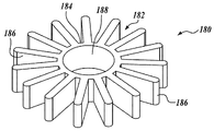
도 11 은 본 발명의 양태들에 따라 댐핑 디바이스를 갖는, 박리 헤드와 같은 작업편의 다른 예의 분해도이다.
도 12 는 박리 디스크가 없는 도 11 의 작업편의 사시도이다.
도 13 은 도 11 의 작업편에서 사용하기 위한 댐핑 디바이스의 일례의 사시도이다.
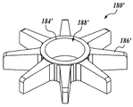
도 14 는 도 11 의 작업편에서 사용하기 위한 댐핑 디바이스의 일례의 사시도이다.
도 15 는 도 11 의 작업편에서 사용하기 위한 댐핑 디바이스의 일례의 사시도이다.1 is a perspective view of an example of a workpiece, such as a peel head, in accordance with aspects of the present invention.
2 is an exploded view of the peeling head of Fig.
3 is a top view of a peeling head such as the peeling head of Fig.
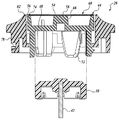
Figure 4 is a cross-sectional view of the peel head of Figure 1 adapted to be connected to parts of a drive motor system.
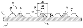
Figure 5 is a partial side view of an example of a surface having abrasive elements on a surface in accordance with aspects of the present invention.
Figure 6 is a partial side view of another example of a surface having abrasive elements on a surface in accordance with aspects of the present invention.
Figure 7 is a partial side view of another example of a surface having abrasive elements on a surface in accordance with aspects of the present invention.
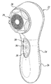
8 is a perspective view of an example of a personal care mechanism equipped with the peeling head of Fig.
Fig. 9 is a side view of the personal care mechanism of Fig. 8 with the peeling head disassembled. Fig.
Figure 10 is a functional block diagram of various components of the personal care appliance of Figure 8;
Figure 11 is an exploded view of another example of a work piece, such as a peel head, having a damping device in accordance with aspects of the present invention.
12 is a perspective view of the work piece of Fig. 11 without a peel disc;
13 is a perspective view of an example of a damping device for use in the workpiece of FIG.
14 is a perspective view of an example of a damping device for use in the workpiece of FIG.
15 is a perspective view of an example of a damping device for use in the workpiece of FIG.
유사한 도면부호들이 유사한 요소들을 가리키는 첨부 도면들과 관련하여 이하에 기재된 상세한 설명은, 개시된 주제의 다양한 실시형태들을 설명하려는 것이고, 오로지 실시형태들을 나타내려는 것은 아니다. 이 개시에서 설명하는 각 실시형태는 단지 예 또는 실례로서 제공되고, 다른 실시형태들보다 바람직한 또는 유리한 것으로 해석되어서는 안 된다. 여기에 제공되는 예시적인 예들은 배타적이거나 또는 청구되는 주제를 개시된 정밀한 형태로 한정하려는 것이 아니다.The following detailed description, taken in conjunction with the accompanying drawings, in which like reference numerals refer to like elements, is intended to describe various embodiments of the disclosed subject matter and is not intended to be exhaustive of the embodiments. Each embodiment described in this disclosure is provided as an example only or an example and should not be construed as preferred or advantageous over other embodiments. The illustrative examples provided herein are not intended to be exhaustive or to limit the claimed subject matter to the precise forms disclosed.
이하의 논의는 피부를 처리하기 위한 시스템, 장치 및/또는 방법의 예들을 제공한다. 여기서 설명하는 예들에서, 개인 관리 기구와 함께 사용되기에 적합한 작업편들이 제공된다. 여기서 설명하는 몇몇 예들에서, 개인 관리 기구는 대상의 영역, 예컨대 피부를 처리하기 위해 작업편을 진동시킨다. 이러한 그리고 다른 실시형태들에서, 작업편은 피부 관리 제제의 앞선 적용을 가지면서 또는 갖지 않으면서 대상의 표피의 향상된 스무딩 (smoothing) 과 박리를 제공하는 트리트먼트 어플리케이터를 포함한다.The following discussion provides examples of systems, devices and / or methods for treating skin. In the examples described herein, work pieces are provided that are suitable for use with personal care equipment. In some examples described herein, the personal care device vibrates the workpiece to treat an area of interest, e.g., skin. In these and other embodiments, the workpiece includes a treatment applicator that provides enhanced smoothing and exfoliation of the skin of the subject with or without prior application of the skin care formulation.
아래에서 더 상세하게 설명되는 바와 같이, 작업편의 진동 작용이 회전 (예컨대, 각도), 병진, 또는 이들의 조합일 수도 있다. 일부 실시형태들에서, 작업편의 운동을 댐핑하기 위한 기술이 제공된다. 이러한 그리고 다른 실시형태에서, 작업편을 구동하는 진동 모터 어셈블리를 조정하는 기술이 제공된다.As will be described in more detail below, the vibrating action of the workpiece may be rotational (e.g., angular), translational, or a combination thereof. In some embodiments, techniques are provided for damping workpiece motion. In these and other embodiments, there is provided a technique for adjusting a vibration motor assembly that drives a workpiece.
사용 중에, 개인 관리 기구는 대상의 표피로부터 각질을 제거하기 위해 대상의 피부 위에서 박리 헤드와 같은 작업편을 진동시킨다. 일부 실시형태들에서, 박리 헤드는 환자의 손이나 발에 형성된 굳은살이나 못과 같은 거친 피부 상태를 치료하는데 사용된다. 예컨대, 박리 헤드는 사용자가 거친 피부 상태를 매끄럽고 윤이 나는 표피 표면으로 만들 수 있게 한다.In use, a personal care device vibrates a workpiece, such as a peel head, over the skin of the subject to remove keratin from the epidermis of the subject. In some embodiments, the peeling head is used to treat rough skin conditions such as hard flesh or nails formed on the patient's hands or feet. For example, the peel head allows the user to make a rough skin condition a smooth, glazed skin surface.
이하의 설명에서, 다수의 특정 세부 사항은 본 개시의 하나 이상의 실시형태들의 철저한 이해를 제공하기 위해 제공된다. 그렇지만, 본 개시의 여러 실시형태들이 특정 세부 사항들의 일부 또는 전부 없이 실시될 수도 있다는 것은 본 기술분야의 통상의 기술자에게 명백할 것이다. 일부 예에서, 잘 알려진 프로세스 단계들은 본 개시의 다양한 양태들을 불필요하게 모호하게 하지 않기 위해 상세하게 기술되지 않는다. 또한, 본 개시의 실시형태들이 여기에 기술된 특징들의 임의의 조합을 채용할 수도 있다는 것을 이해할 것이다.In the following description, numerous specific details are set forth in order to provide a thorough understanding of one or more embodiments of the disclosure. However, it will be apparent to those of ordinary skill in the art that various embodiments of the present disclosure may be practiced without some or all of the specific details. In some instances, well known process steps are not described in detail in order not to unnecessarily obscure the various aspects of the present disclosure. It will also be appreciated that embodiments of the present disclosure may employ any combination of the features described herein.
이제, 도 1 을 참조하면, 본 개시의 양태들에 따라 형성된 박리 헤드 (20) 형태의 작업편의 일례가 도시되어 있다. 박리 헤드 (20) 는 도 8 및 도 9 에 도시된, 기구 (22) 와 같은 개인 관리 기구와 함께 사용하기에 적합하다. 아래에서 더 상세하게 설명되는 바와 같이, 박리 헤드 (20) 는 표피로부터 각질 세포를 제거하기 위해 대상의 피부 위에서 진동될 수 있는 연마 섹션 (60) 을 갖는 표면 (58) 을 포함한다. 또한, 아래에서 더 상세하게 설명되는 바와 같이, 일부 실시형태들은 헤드 (20) 를 진동시키기 위해 음속 운동 (sonic motion) 을 이용하고, 이는 스컬프팅 (sculpting) 및 굳은살 제거에 향상된 제어 및 정밀도를 제공할 수 있다. 아래에서 더 상세하게 설명되는 바와 같이, 이러한 음속 운동은 그의 의도되는 적용에 따라 댐핑 및/또는 튜닝될 수 있다.Referring now to Figure 1, an example of a workpiece in the form of a
헤드 (20) 를 더 상세하게 설명하기 전에, 헤드 (20) 에 진동 운동을 부여하는데 채용될 수도 있는 개인 관리 기구 (22) 의 일례를 약간 상세하게 설명한다. 개인 관리 기구 (22) 가 본 개시의 실시형태들로 실행될 수 있는 기구의 한 종류이지만, 헤드 (20) 가 넓은 범위의 진동 (oscillatory) 또는 요동 (vibratory) 운동 생성 디바이스들과 함께 사용되기에 적합하다고 이해될 것이다.Before describing the
이제, 도 8 및 도 9 를 참조하면, 개인 관리 기구 (22) 의 일례가 도시되어 있다. 개인 관리 기구 (22) 는 핸들 부분 (26) 과 헤드 부착부 (28) 를 갖는 보디 (24) 를 포함한다. 헤드 부착부 (28) 는 박리 헤드 (20) 와 같은 헤드를 기구 (22) 에 선택적으로 부착시키도록 구성되어 있다. 기구 보디 (24) 는 기구의 작동 구조체를 수납한다. 도 10 의 블록도에 도시된 바와 같이, 일 실시형태에서 작동 구조체는 구동 모터 어셈블리 (30), 충전지와 같은 동력 저장 소스 (32), 및 동력 저장 소스 (32) 로부터 구동 모터 어셈블리 (30) 로 동력을 선택적으로 전달하도록 구성되고 배치된 온/오프 버튼 (36) (도 8 참조) 을 구비하는 구동 제어부 (34) 를 포함한다. 일부 실시형태들에서, 구동 제어부 (34) 는 프로그램된 마이크로컨트롤러 또는 프로세서와 같은 제어 회로 (이는 구동 모터 어셈블리 (30) 로의 동력의 전달을 제어하도록 구성됨) 에 연결된 동력 조절 또는 모드 제어 버튼들 (38) (도 8 참조) 을 또한 포함할 수도 있다. 구동 모터 어셈블리 (30) 는 몇몇의 실시형태들에서, 구동 샤프트 또는 아마추어 (42) 를 통해 박리 헤드 (20) 와 같은 부착된 헤드를 구동하는 전기 구동 모터 (40) 를 포함한다.8 and 9, an example of
박리 헤드 (20) 와 같은 작업편이 헤드 부착부 (28) 에 장착되는 때, 구동 모터 어셈블리 (30) 는 헤드 (20) 에 운동을 부여하도록 구성된다. 구동 모터 어셈블리 (30) 는 전형적으로 90-300 ㎐ 의 범위 내의 음속 진동수로 박리 헤드 (20) 를 작동시키도록, 특히 8-26 도의 각도상 범위 내에서 박리 헤드 (20) 를 앞뒤로 진동시키도록 구성될 수도 있다. 일부 실시형태들에서, 아래에서 더 상세하게 설명되는 바와 같이, 박리 헤드 (20) 는 약 12-18 도의 진폭 또는 범위로 약 100 ㎐ 내지 190 ㎐ 의 진동수로 작동된다. 다른 실시형태들에서, 박리 헤드 (20) 는 약 168 ㎐ 내지 178 ㎐ 의 진동수, 약 12-18 도의 진폭, 및 약 36-48 % 의 듀티 사이클로 작동된다.The
박리 헤드 (20) 를 진동시키기 위해 기구 (22) 에 의해 채용될 수 있는 구동 모터 어셈블리 (30) 의 일례가 미국특허 제 7,786,626 호에 기재되고 설명되어 있다. 그렇지만, 이는 단지 하나의 그러한 기구의 구조 및 작동의 일례이고, 그러한 기구의 구조, 작동 진동수 및 진동 진폭이 부분적으로 박리 헤드의 의도되는 적용 및/또는 특성 (관성 특성 등) 에 따라 달라질 수 있다는 것을 이해하여야 한다. 본 개시의 일부 실시형태들에서, 진동수 범위는 부착된 헤드를 근공진 (near resonance) 으로 구동하도록 선택된다. 따라서, 선택된 진동수 범위들은 부착된 헤드의 관성 특성에 부분적으로 의존한다. 부착된 헤드를 근공진으로 구동하는 것은, 하중 조건에서 (예컨대, 피부와 접촉한 때에) 부착된 헤드를 적절한 진폭으로 구동할 수 있는 능력을 포함하여 많은 이점을 제공하는 것을 이해할 것이다. 기구의 일례의 설계 파라미터들에 대한 더 상세한 논의에 대해서는, 미국특허 제 7,786,626 호를 참조하라.One example of a
이제, 도 2 내지 도 4 를 참조하여, 박리 헤드 (20) 의 일례를 더 상세하게 설명한다. 도 2 및 도 4 에 가장 잘 도시된 것처럼, 헤드 (20) 는 일반적으로 원통형의 가동 중앙부 (44) 를 포함한다. 가동 중앙부 (44) 는 제 1 또는 내측 단부 (52) 에서 구동 모터 어셈블리 (30) 의 구동 샤프트 또는 아마추어 (42) 와 직접적으로 또는 간접적으로 (예컨대, 구동 보스 (50) 를 통해) 접속하도록 구성된 베이스 섹션 (48) 을 포함한다. 베이스 섹션 (48) 은, 알루미늄, 티타늄 등과 같은 경량 금속을 포함하는 다른 재료가 사용될 수도 있지만, 나일론, 폴리우레탄, 폴리프로필렌, 폴리에틸렌 등과 같은 플라스틱으로 구성된 것으로서 도 4 에 도시되어 있다.Now, referring to Figs. 2 to 4, an example of the peeling
가동 중앙부 (44) 는 반대편의 제 2 또는 외측 단부 (56) 에서, 베이스 섹션 (48) 에 고정 부착된 디스크 플레이트 (54) 를 더 포함한다. 도시된 실시형태에서, 디스크 플레이트 (54) 는 하나 이상의 연마 섹션들 (60) 을 갖는 헤드 (20) 의 외향 표면 (58) 을 형성한다. 디스크 플레이트 (54) 는, 나일론, 폴리우레탄, 폴리프로필렌, 폴리에틸렌 등과 같은 플라스틱을 포함하는 다른 재료가 사용될 수도 있지만, 스테인리스강, 은, 아연, 황동, 구리, 알루미늄, 금 등과, 이들의 합금들 그리고 이의 조합들과 같은 금속으로 구성된 것으로서 도 3 에 도시되어 있다. 일부 실시형태들에서, 디스크 플레이트 (54) 는 알루미늄이나 스테인리스강과 같은 더 경제적이거나 더 가벼운 금속으로부터 구성된 내부 코어, 및 아연, 구리, 금 또는 은과 같은 더 생체적합한 금속으로부터 구성된 외부 층을 포함할 수도 있다.The movable
도 2 및 도 4 에 도시된 실시형태에서, 베이스 섹션 (48) 은 숄더 또는 단차 섹션 (66) 과 함께 주변으로 연장된 외측 림 (64) 에 의해 규정된 개방단 캐비티 (open-ended cavity; 62) 를 포함한다. 캐비티 (62) 의 중앙에는, 단차 섹션 (66) 의 지지 표면 (72) 과 대체로 동일 평면에 있는 상부 지지 표면 (70) 을 갖는 중앙 보스 (68) 가 배치된다. 일 실시형태에서 베이스 섹션 (48) 에 대해 디스크 플레이트 (54) 를 확고하게 고정하기 위해, 디스크 플레이트 (54) 는 보스 (70) 와 숄더 (66) 상에 먼저 위치되고 이에 의해 지지된다. 그리고, 림 (64) 은 숄더 (66) 와 다이 형성된 플랜지 (74) 사이에 디스크 플레이트 (54) 를 붙잡도록 다이 형성된다. 일부 실시형태들에서, 다이 형성된 플랜지 (74) 는 연마 섹션들 (60) 의 일부 위에 그리고 일부와 맞물리도록 연장된다. 다른 고정 방법이 채용될 수 있다고 이해될 것이다. 예컨대, 디스크 플레이트 (54) 는 베이스 섹션 (48) 에 접착 결합될 수 있다.2 and 4, the
가동 중앙부 (44) 의 예들이 개별 베이스 섹션 (48) 및 디스크 플레이트 (54) 인 것으로서 묘사되고 설명되었지만, 본 개시에 의해 중앙부 (44) 의 다른 구성들이 고려된다. 예컨대, 일부 실시형태들에서, 중앙부 (44) 는 금속 또는 플라스틱의 단일형 (unitary) 부재일 수 있고, 주조, 성형, 공동 성형 (co-molding), 또는 다른 종래의 기술에 의해 형성될 수 있다.Although the examples of the
일부 실시형태들에서, 베이스 섹션 (48) 은 하나 이상의 추가적인 특징을 또한 포함할 수도 있다. 예컨대, 박리 헤드 (20) 는 공진 시스템에서 사용되도록 특별히 제작될 수 있다. 이와 관련하여, 작동 동안에 헤드 (20) 의 관성 특성을 유지하려고 노력하는 것이 중요할 수도 있다. 따라서, 내측 캐비티 (72) 에 접근할 수도 있는 임의의 유체 및/또는 고형물을 제거하기 위해, 내측 캐비티 (72) 의 주변 주위에 하나 이상의 드레인 구멍들 또는 슬롯들 (76) 이 제공될 수도 있다. 헤드 (20) 가 음속 운동 발생기와 함께 사용되도록 설계되는 때, 시스템 (예컨대, 구동 모터 어셈블리 (30) 및 헤드 (20)) 은 과도한 또는 해로운 박리 압력이 가해진다면 정지하도록 설계될 수 있다는 것을 이해할 것이다. 또한, 도 11 의 실시형태와 관련하여 아래에서 더 상세하게 더욱 묘사되는 것처럼, 그러한 진동 운동은 그의 의도되는 적용에 따라 댐핑 및/또는 튜닝될 수 있다.In some embodiments, the
도 2 내지 도 4 로 돌아와서, 헤드 (20) 는 일부 실시형태들에서 선택적인 외측 리테이너 (78) 를 포함한다. 외측 리테이너 (78) 는 실린더형상의 중앙 개구 (80) 를 포함한다. 개구 (80) 는 가동 중앙부 (44) 의 측들을 둘러싸도록 구성되고 크기결정된다. 기구 (22) 에 부착되는 때, 중앙 개구 (80) 의 상부 주변 주위에 연장되는 림 (82) 이 가동 중앙부 (44) 의 외측 표면 (58) 와 동일 평면상에 있거나 약간 아래에 또는 내측에 (즉, 헤드 부착부 (28) 를 향해) 위치된다.Returning to Figures 2-4, the
일부 실시형태들에서, 중앙부 (44) 및 외측 리테이너 (78) 는 개인 관리 기구 (22) 의 헤드 부착부 (28) 에 대한 헤드 (20) 의 선택적 부착을 제공하도록 구성된 부착 시스템을 함께 포함한다. 부착 시스템에 의해 개인 관리 기구 (22) 에 부착되는 때, 다음이 일어난다: (1) 가동 중앙부 (44) 가 예컨대 구동 보스 (50) 를 통해 진동 운동을 제공하는 방식으로 구동 모터 어셈블리 (30) 에 작동식으로 연결되고, (2) 리테이너 (78) 가 기구 (22) 에 헤드 (20) 를 확고하게 고정시킨다. 따라서, 부착 시스템은 일부 실시형태들에서 개인 관리 기구 (22) 에 헤드 (20) 를 부착 및 탈착시키기 위한 빠르고 쉬운 기술을 제공한다. 부착 시스템은 다른 개인 관리 헤드들이 핸들에 부착될 수 있게 하고 원하는 때에 대체 박리 헤드들이 기구 (22) 에 부착될 수 있게 한다는 것을 이해할 것이다.In some embodiments, the
본 개시의 실시형태들로 실행될 수 있는 일 부착 시스템이 미국특허 제 7,386,906 호에 기재되어 있다. (1) 중앙부 (44) 에 진동 운동을 제공하고 (2) 중앙부 (44) 와 구동 모터 어셈블리 (30) 사이의 연결을 유지하는 방식으로 기구 (22) 와 같은 개인 관리 기구에 헤드 (20) 를 선택적으로 부착시키기 위해 공구를 사용하는 또는 사용하지 않는 기술을 제공하기 위해 다른 부착 시스템들이 채용될 수 있다는 것을 이해할 것이다. 예컨대, 일부 실시형태들에서, 중앙부 (44) 는 중앙부 (44) 를 확고하게 고정하면서 중앙부 (44) 에 진동 운동을 전달하는 방식으로 관련 구동 모터 어셈블리 (30) 의 진동 구동 샤프트 또는 아마추어 (아마추어 (42) 등) 에 상호협력작동식으로 연결되도록 구성된 커플링 인터페이스를 포함한다. 따라서, 리테이너 (78) 가 헤드 (20) 의 일부 실시형태에 특정 이점을 제공할 수도 있지만, 리테이너는 선택적이므로, 원한다면 생략될 수도 있다는 것을 이해하여야 한다.One attachment system that can be implemented with the embodiments of the present disclosure is described in U.S. Patent No. 7,386,906. (20) to a personal care device, such as a device (22), in such a manner as to provide a vibratory motion to the central portion (44) of the drive motor assembly (30) It will be appreciated that other attachment systems may be employed to provide a technique with or without a tool for selectively attaching. For example, in some embodiments, the
이제, 도 3, 도 5 내지 도 7 을 참조하여, 연마 섹션들 (60) 을 갖는 표면 (58) 의 양태들을 더 상세하게 설명한다. 도 5 에 도시된 것처럼, 외향 표면 (58) 의 연마 섹션들 (60) 은 대상의 표피의 각질을 박리하기에 충분하게 구성된다 복수의 이격된 연마 요소들 (84) 을 포함한다. 이와 관련하여, 연마 요소들 (84) 은 여기서 박리 돌출부들 (84) 이라고 칭할 수도 있다. 아래에서 더 상세하게 설명되는 바와 같이, 연마 요소들 (84) 은 부분적으로 의도되는 적용에 따라 많은 구성들을 가질 수 있다.Referring now to Figures 3, 5 to 7, aspects of
일부 실시형태들에서, 복수의 연마 요소들 (84) 은 손, 팔꿈치 또는 발과 같은 신체의 영역들에서 일만적인 각질 제거를 제공하도록 구성된다. 다른 실시형태들에서, 복수의 연마 요소들은 굳은살, 못 등이 형성된 손이나 발과 같은 신체의 거친 영역들을 스컬프팅 및/또는 스무딩하기 위해 피부와의 더 공격적인 맞물림을 제공하도록 구성된다. 본 개시의 실시형태들에서, 연마 요소들 (84) 은 강모 (bristles) 를 포함하지 않는다. 따라서, 이 실시형태들의 박리 헤드들은 브러시없는 박리 헤드들로서 칭해질 수 있다.In some embodiments, the plurality of
연마 요소들 (84) 의 각각은 표면 (58) 에 걸쳐 동일한 또는 유사한 구성을 가질 수 있다. 대안적으로, 연마 요소들 (84) 의 구성은 표면 (58) 에 걸쳐 또는 연마 섹션들 (60) 사이에서 달라질 수도 있다. 아래에서 더 상세하게 설명되는 바와 같이, 일부 실시형태들의 연마 요소들 (84) 은 약 0.003 인치 (0.0762 밀리미터) 내지 약 0.008 인치 (0.203 밀리미터) 의 높이로 디스크 플레이트 (56) 의 표면 (58) 으로부터 외측으로 돌출한다. 일부 실시형태들에서, 디스크 플레이트는 표면 (58) 의 하나 이상의 섹션들에서 제곱 인치당 2200 개 이하의 연마 요소들을 포함한다.Each of the
일부 실시형태들에서, 연마 요소들 (84) 이 랜덤 방식으로 배치될 수 있는 한편, 다른 실시형태들에서, 연마 요소들 (84) 이 하나 이상의 패턴으로 배치될 수 있다는 것을 이해할 것이다. 이 실시형태들에서, 하나 이상의 패턴은 표면 (58) 의 대부분에 걸쳐 일정하거나 또눈 표면 (58) 의 소부분이나 대부분 또는 그의 일부에 걸쳐 달라질 수 있다. 도시된 실시형태들에서 표면은 다른 구성을 채용할 수도 있지만 어떠한 연마 요소들 (84) 이 없는 그의 중앙에 위치된 섹션 (86) 을 포함한다. 일부 실시형태들에서, 섹션 (86) 은 대상 등의 곡선형 표면 위를 가로지를 때에 중앙부 (44) 의 조기 스톨링 (premature stalling) 의 방지를 돕기 위해 매끄러운 표면을 갖는다. 이러한 실시형태들에서, 섹션 (86) 의 매끄러운 표면은 표면 (58) 의 약 10 % 이상을 차지한다.It will be appreciated that, in some embodiments, the
본 개시의 일부 양태들에 따르면, 연마 요소들 (84) 은 부가적인 프로세스를 통해 외향 표면 (58) 에 매립, 접착, 부착, 형성, 배치되거나 또는 그렇지 않으면 제공될 수 있다. 일부 실시형태들에서, 연마 요소들 (84) 은 다이아몬드 칩들 또는 다이아몬드 더스트, 실리콘 카바이드, 알루미늄 옥사이드, 샌드, 예컨대 실리카, 칼슘 카보네이트 등, 알루미나-지르코늄, 푸마이스, 및 이들의 조합을 포함하는 (이들로 제한되지 않음) 작은 연마 입자들로 구성된다. 일부 실시형태들에서, 연마 입자들의 평균 직경은 약 45 미크론 내지 약 250 미크론, 또는 그 이상이다.According to some aspects of the present disclosure, the
연마 요소들 (84) 을 형성하기 위해 채용될 수 있는 부가적인 프로세스의 더 간단한 예들 중의 하나에서, 60-300 사이의 그릿 (grit) 을 갖는 사포 등이 디스크 플레이트 (54) 의 표면 (58) 에 접착 결합될 수 있다. 일부 실시형태들에서 채용될 수도 있는 다른 부가적인 프로세스는 도금 또는 코팅이다. 예컨대, 디스크 플레이트 (54) 가 금속으로 이루어진 실시형태들에서, 내부에 배치된 연마 입자의 슬러리를 갖는 니켈, 은, 금, 티타늄, 지르코늄, 크롬과 같은 금속 및/또는 그의 산화물, 이산화물 등의 층이 특히 전기 또는 무전해 도금법, 진공 증착 기술, 예컨대 화학 기상 증착, 물리 기상 증착 등, 스퍼터링 증착, 음극 아크 증착, 플라스마 증착을 이용하여 디스크 플레이트 (54) 에 도금될 수 있다.In one of the simpler examples of additional processes that may be employed to form the
디스크가 플라스틱으로 이루어진 실시형태들에서, 연마 요소들 (84) 은 예컨대, 진공 증착 기술을 이용하여 예컨대 은이나 금의 얇은 베이스 층을 먼저 형성함으로써 그것에 고정될 수 있다. 일단 베이스 층이 디스크 플레이트 (54) 에 적용되고 나면, 내부에 배치된 연마 입자들의 슬러리를 갖는 니켈, 은, 금, 티타늄, 지르코늄, 크롬과 같은 금속, 및/또는 그의 산화물, 이산화물 등의 층이 전기 또는 무전해 도금법을 이용하여 베이스 층에 도금될 수 있다. 전기 또는 무전해 도금 외에, 플라스틱 디스크 플레이트에 연마 입자들을 고정시키기 위해 특히 접착 결합 또는 플라스마 증착의 이용과 같은 다른 기술이 사용될 수 있다. 다른 실시형태들에서, 디스크 플레이트 (54) 는 함께 배치된 연마 입자들을 갖는 플라스틱 수지와 공동 성형될 수 있다.In embodiments where the disk is plastic, the
본 개시의 다른 양태들에 따르면, 연마 요소들 (84) 은 서브트랙티브 (subtractive) 프로세스를 통해 외향 표면 (58) 에 형성되거나 또는 그렇지 않으면 제공될 수 있다. 일부 실시형태들에서, 펄스 레이저 증착 프로세스가 채용될 수도 있다. 다른 실시형태들에서, 연마 요소들 (84) 은 디스크 플레이트 (54) 의 표면 (58) 이 되도록 화학적으로 에칭된다. 이와 관련하여, 일부 실시형태들에서, 디스크 플레이트 (54) 는 디스크 플레이트 (54) 의 표면에 박리 돌출부들을 형성하도록 소정의 패턴 및 에칭 프로토콜에 따라 포토에칭된다.In accordance with other aspects of the present disclosure, the
도 5 는 본 개시의 양태들에 따라 에칭 프로세스에 의해 형성된 연마 요소들 (84) 의 일례의 기하학적 형상의 부분 확대도이다. 도 5 의 측면도에 가장 잘 도시된 바와 같이, 연마 요소들 (84) 은 일반적으로 절삭 에지들 (94) 을 규정하는 일반적으로 평평한 상부 표면 (90) 을 갖는, 일반적으로 절두 원뿔형 형상이다. 상부 표면 (90) 의 직경 (D1) 은 일부 실시형태들에서 연마 요소들 (84) 의 베이스의 직경 (D2) 의 약 30 % - 60 % 이고, 다른 실시형태들에서 약 48-52 % 이다. 다양한 실시형태들에서, 상부 표면 (90) 의 직경 (D1) 은 0.004 인치 (0.0102 밀리미터) 내지 0.008 인치 (0.203 밀리미터) 이다. 일반적으로 절두 원뿔형인 것으로 설명 내지 묘사되지만, 연마 요소들 (84) 은 절두 피라미드와 같이 내측으로 테이퍼지고 절두형의 다른 기하학적 형상 (예컨대, 절두 피라미드형 등) 을 가질 수도 있다.5 is a partial enlarged view of an example geometry of polishing
연마 요소들 (84) 의 다른 특징은 일부 실시형태들에서 약 0.004 인치 (0.0102 밀리미터) 내지 0.008 인치 (0.203 밀리미터) 의 돌출 높이 (H) 를 포함하고, 다른 실시형태들에서 약 0.006 인치 (0.152 밀리미터) 및 0.008 인치 (0.203 밀리미터) 의 높이 (H) 를 포함한다. 일부 실시형태들에서, 디스크 플레이트 (54) 는 다소 과다에칭될 수 있고, 이로써 도 6 의 예에 가장 잘 보여진 것처럼 일반적으로 오목한 측벽들 (92) 또는 그의 부분들을 형성한다. 다른 실시형태들에서, 도 7 에 가장 잘 보여진 것처럼, 상부 표면 (90) 의 더 현저한 상부 또는 절삭 에지들 (94) 이 형성될 수 있다. 이 실시형태에서, 연마 요소들 (84) 의 측벽들은 일반적으로 절두 원뿔형 베이스 섹션 (96) 및 일반적으로 실리더형 상부 섹션 (98) 을 포함한다. 일부 실시형태들에서, 베이스 섹션 (96) 으로부터 상부 섹션 (98) 으로의 측벽들 전이부 (T) 는 상부 표면 (90) 으로부터 약 0.0005 인치 (0.0127 밀리미터) 내지 0.002 인치 (0.0508 밀리미터) 에 있다. 일부 실시형태들에서, 상부 섹션 (98) 의 측벽들과 상부 표면 (90) 사이에 형성되는 각도 (α) 는 바람직하게는 90 도 이하이다.Other features of the
연마 요소들의 하나 이상의 실시형태들의 상기한 기하학적 형상은 에칭 프로세스에 의해 형성될 수 있다. 그렇지만, 이러한 특징들 중의 하나 이상을 갖는 연마 요소들이 여기서 설명된 부가 및 서브트랙티브 프로세스들 쌍방을 포함하는 다른 제조 방법으로 획득될 수 있다는 것을 이해할 것이다. 더욱이, 원한다면, 연마 표면의 윤활성 및/또는 생체적합성을 향상시키기 위해, 종래의 코팅 기술을 통해 티타늄 이산화물, 지르코늄 이산화물, 크롬 이산화물, 금, 은, 구리, 아연 등의 얇은 필름 (예컨대, 0.0001 인치 (0.00254 밀리미터)) 이 연마 요소들 (80) 에 코팅될 수 있다.The geometric shape of one or more embodiments of the abrasive elements may be formed by an etching process. It will be appreciated, however, that polishing elements having one or more of these features may be obtained with other fabrication methods, including both additive and subtractive processes described herein. Furthermore, thin films of titanium dioxide, zirconium dioxide, chromium dioxide, gold, silver, copper, zinc and the like (for example, 0.0001 inches thick) can be deposited by conventional coating techniques, if desired, to improve the lubrication and / 0.00254 millimeters) may be coated on the abrasive elements 80.
도 11 은 본 개시의 양태들에 따라 형성된, 박리 헤드 (120) 와 같은 작업편의 다른 실시형태를 보여준다. 박리 헤드 (120) 는, 이제 설명하는 차이점을 제외하고 구성, 재료 및 작동에 있어서 전술한 박리 헤드 (20) 와 실질적으로 유사하다.11 shows another embodiment of a workpiece, such as the
전술한 바와 같이, 여러 실시형태들은 헤드 (20) 에 진동 운동을 부과하기 위해 진동 구동 모터 어셈블리를 채용한다. 이와 관련하여, 구동 모터 어셈블리 (30) 와 같은 구동 모터 어셈블리는 전형적으로 90-300 ㎐ 의 음속 진동수로 박리 헤드 (20) 를 작동시켜 예컨대 8-26 도의 각도상 범위 내에서 박리 헤드 (20) 를 전후로 진동시키도록 구성될 수도 있다.As described above, various embodiments employ vibration driven motor assemblies to apply vibratory motion to the
이러한 시스템에서, 박리 헤드 (20) 는 "높은 Q" 처리 기구 또는 작업편으로서 분류될 수 있다. 결과적으로, 공진 또는 근공진으로 상기한 진동수로 작동하는 때, 원하지 않는 작업편 운동이 존재할 수 있다. 특히, 구동 모터 어셈블리 (30) 에 의해 구동되는 때에, 동심이 아닌 (즉, 비틀림) 평면의 운동 및/또는 비평면의 굽힘 운동 (예컨대, 헤드 (20) 의 주된 진동 평면에 있지 않은 운동, 이는 예컨대 일부 실시형태들에서 디스크 플레이트와 동일 평면에 있을 수 있음) 과 같은 헤드 (20) 의 기생 운동 (parasitic motion) 이 존재할 수도 있다. 아래에서 더 상세하게 설명되는 바와 같이, 구동 모터 어셈블리 (30) 와 같은 근공진 개인 관리 기구의 진동하는 모터 시스템을 튜닝할 수 있기 위한 그리고 헤드 (20) 의 원하지 않는 잠재적인 운동을 댐핑하기 위한 기술들이 제공된다.In such a system, the peeling
이와 관련하여, 그리고 본 개시의 양태들에 따라, 도 11 의 박리 헤드 (120) 는 강진 또는 근공진으로 작동되는 때에 헤드 (120) 의 운동을 댐핑하기 위한 수단을 제공하는 댐핑 디바이스 (180) 를 포함한다. 댐핑 디바이스 (180) 를 제공함으로써, 진동 모터 어셈블리 (30) 는 원하는 작동 진동수 대역으로 튜닝될 수 있다.In this regard, and in accordance with aspects of the present disclosure, the peeling
도 11 내지 도 13 에 도시된 실시형태에서, 댐핑 디바이스 (180) 는 링 (184) 을 갖는 가요성 부재 (182) 를 포함하고, 링으로부터 복수의 베인들 (vanes; 186) 이 반경방향으로 연장된다. 링 (184) 은 중앙 보어 (188) 를 규정하고, 중앙 보어는 조립되는 때에 중앙부 (44) 의 중앙 보스 (68) 를 수용하도록 구성된다. 결과적으로, 댐핑 디바이스 (180) 는 도 12 에 도시된 것처럼 보스 (68) 에 장착된다. 선택적인 웨빙 (webbing; 도시 안 됨) 이 하나 이상의 베인들 (186) 사이에 배치될 수도 있고, 링 (182) 으로부터 반경방향 외측으로 연장되거나 또는 베인들의 (186) 의 팁과 링 (184) 의 반경방향 외측의 위치 사이에 연장될 수도 있다. 일부 실시형태들에서, 가요성 부재 (182) 는 X 및 Y 축 쌍방을 따라 대칭이다.11-13, the damping
일부 실시형태들에서 가요성 부재 (182) 는 엘라스토머 재료로부터 제조된다. 엘라스토머 재료는 약 10 Shore A 내지 약 100 Shore A 의 적절한 경도를 가질 수도 있다. 가요성 부재 (182) 는 TPE 사출 성형, 실리콘을 사용하는 저압 사출 성형, 주조, 시트 엘라스토머 재료로부터의 펀칭 등을 포함하는 (이에 제한되지 않음) 다양한 프로세스에 의해 구성될 수 있다. 일부 실시형태들에서, 베인들 (186) 은 스프링 강, 강현 (piano wire) 요소들과 같은 굽힘 특성을 갖는 금속으로 구성될 수도 있다. 도 14 는 댐핑 디바이스 (180') 의 다른 실시형태를 보여준다. 진동하는 구동 모터 어셈블리 (30) 를 튜닝하기 위해 댐핑 디바이스 (180, 180') 의 경도 값뿐만 아니라 베인들의 두께, 길이 및 폭이 달라질 수 있다는 것을 이해할 것이다.In some embodiments, the
도 15 는 본 개시의 양태들에 따라 형성된 댐핑 디바이스 (280) 의 다른 실시형태이다. 댐핑 디바이스 (280) 는 헤드의 운동에 댐핑을 제공하기 위해 그리고 진동하는 구동 모터 어셈블리 (30) 에 튜닝을 제공하기 위해 헤드 (120) 와 함께 사용하기에 적합하다. 도 15 에 도시된 것처럼, 댐핑 디바이스 (280) 는 엘라스토머 재료의 가요성 시트 (282) 를 포함하고, 가요성 시트로부터 복수의 리지들 (284) 및 돌기부들 (286) 이 외향 연장된다. 도시된 실시형태에서, 리지들 (284) 은 서로 이격되어 있고 시트 (282) 의 중앙 보어 (288) 로부터 반경방향 외측으로 연장된다. 일부 실시형태들에서, 돌기부들 (286) 은 리지들 (284) 사이에서 이격된 방식으로 그룹으로 나눠진다. 도시된 실시형태에서, 시트 (282) 는, 다른 다각형의 그리고 비-가각형의 대칭 형상이 사용될 수도 있지만, 일반적으로 팔각형 형상을 갖는다. 헤드 (120) 의 우동을 댐핑하기 위해 그리고 진동하는 구동 모터 어셈블리 (30) 를 튜닝하기 위해, 엘라스토머 재료의 경도 값뿐만 아니라 리지들 (284) 및 돌기부들 (286) 의 치수 (예컨대, 높이, 두께, 길이, 직경 등) 및 위치가 달라질 수 있다는 것을 생각할 수 있다.Figure 15 is another embodiment of a damping
박리 헤드 (20, 120) 의 상기한 예들은 대상의 표피의 피부를 박리하는데 사용될 수 있고, 일부 실시형태들에서, 굳은살이나 못과 같은 부분적으로 각질화된 세포들에 의해 야기된 거친 피부 상태를 줄이거나 제거하는데 사용될 수 있다. 이와 관련하여, 박리 헤드 (20 또는 120) 는 개인 관리 기구 (22) 에 먼저 부착된다. 다음으로, 개인 관리 기구 (22) 가 켜지고, 관련 박리 기구가 90-300 ㎐ 의 진동수로 작동되어, 박리 헤드를 8-26 도의 범위 내에서 전후로 진동시킨다. 일부 실시형태들에서, 관련 박리 헤드는 약 12-18 도의 진폭 또는 범위로 약 100㎐ 내지 190 ㎐ 의 진동수로 작동된다. 다른 실시형태들에서, 관련 박리 헤드는 약 168 ㎐ 내지 178 ㎐ 의 진동수, 약 12-18 도의 진폭이나 범위, 그리고 약 36-48 % 의 듀티 사이클로 작동된다.The above examples of the peeling heads 20 and 120 may be used to peel the skin of the epidermis of the subject and in some embodiments have a rough skin condition caused by partially keratinized cells such as hard flesh or nails Can be used to reduce or eliminate. In this regard, the peeling
일단 진동되고 나면, 박리 헤드 (20, 120) 의 연마 표면은 발이나 손과 같은 신체의 피부의 거친 영역에 대해 적용되고 그 위에서 움직여진다. 상기한 진폭 및 진동수로 작동되는 연마 표면의 진동 작용은 박리 효과를 제공하여서, 피부의 거친 영역을 스컬프팅하고, 못, 굳은살 등을 제거하거나 감소시킨다. 일부 실시형태들에서, 시스템은 사용자가 피부에 대해 너무 많은 힘을 가하면 시스템이 정지하도록 구성된다. 일단 영역이 원하는 양만큼 스컬프팅되면, 박리 헤드 (20, 120) 의 연마 표면은 피부로부터 제거될 수 있고, 기구 (22) 는 꺼질 수 있다. 대안적으로, 기구 (22) 는 프로그램된 작동을 통해 자동으로 꺼질 수 있다.Once oscillated, the polishing surface of the peeling
따라서, 이상에서 개략적으로 설명한 대표적인 프로세스에 있어서, 특정 진동수 및 진폭 범위에서, 전술한 바와 같은 박리 헤드 (20, 120) 의 예들을 이용하면, 피부 스컬프팅 및/또는 굳은살/못 제거에 향상된 제어 및 정밀도가 얻어진다. 또한, 박리 헤드 (20, 120) 로 피부를 박리하는 때에 부가적인 이점들이 실현될 수 있다. 예컨대, 헤드에 부여되는 진동 운동의 결과로서 헤드 (20, 120) 의 각각의 지향성 변화로 피부가 제거될 수 있으므로, 종래의 회전 동력식 디바이스나 수동식 디바이스에 비해 더 적은 힘으로 더 많은 피부가 제거될 수 있다.Thus, in the exemplary process outlined above, using the examples of the peeling
전술한 방법은 피부 관리 제제의 사용이나 피부를 따듯한 물에 담금으로써 피부를 부드럽게 하는 시도 없이 수행될 수 있다. 그렇지만, 박리 이전의 피부 영역의 임의의 준비가 전술한 방법의 일부로서 이용될 수 있다.The methods described above can be carried out without the use of a skin care formulation or the attempt to soften the skin by immersing the skin in warm water. However, any preparation of the skin area prior to exfoliation may be used as part of the method described above.
이 개시의 목적을 위해, "상부", "하부", "수직방향", "수평방향", "전", "후", "내측", "외측", "내향", "외향", "전방", "후방" 등과 같은 용어는 청구되는 주제의 범위를 제한하는 것이 아니라 묘사하는 것으로서 해석되어야 한다. 또한, 여기에서 "구비하는", "포함하는" 또는 "갖는" 그리고 이들의 변형의 사용은 열거된 아이템들 및 그의 등가물뿐만 아니라 추가적인 아이템들을 포함하려는 것이다. 달리 제한되지 않는 한, 여기서 용어 "연결된", "커플링된" 및 "장착된" 그리고 이들의 변형은 폭넓게 사용되며, 직접적인 그리고 간접적인 연결, 커플링 및 장착을 포함한다.For purposes of this disclosure, the terms "top," "bottom," "vertical," "horizontal," "front," "back," "medial," " Front, "" rear," and the like, should be interpreted as describing rather than limiting the scope of the claimed subject matter. Also, the use of "comprising", "comprising" or "having" and variations thereof herein is meant to include additional items as well as enumerated items and equivalents thereof. Unless otherwise limited, the terms "coupled," " coupled, "and " mounted, " and variations thereof, are used extensively and include direct and indirect connections, couplings, and mountings.
본 개시의 작동의 원리들, 대표적인 실시형태들, 및 모드들이 이상의 설명에 기재되어 있다. 그렇지만, 보호받으려는 본 개시의 양태들은 개시된 특정 실시형태들로 제한되는 것으로 해석되어서는 안 된다. 더욱이, 여기서 설명된 실시형태들은 제한적이라기 보다는 설명적인 것으로 간주되어야 한다. 본 개시의 사상으로부터 벗어남이 없이, 채용되는 균등물 및 다른 것들에 의해 변형 및 변화가 행해질 수도 있다는 것을 이해할 것이다. 따라서, 그러한 모든 변형, 변화 및 균등물이 청구되는 바와 같은 본 개시의 사상 및 범위 내에 속하는 것이 명확히 의도된다.The principles, exemplary embodiments, and modes of operation of the present disclosure are set forth in the foregoing description. However, aspects of the disclosure to be protected should not be construed as limited to the specific embodiments disclosed. Moreover, the embodiments described herein should be considered illustrative rather than restrictive. It will be understood that variations and modifications may be made by equivalents employed and others, without departing from the spirit of the disclosure. Accordingly, it is expressly intended that all such modifications, variations, and equivalents be within the spirit and scope of the present disclosure as claimed.
Claims (53)
상기 구동 시스템에 작동식으로 커플링되도록 구성된 가동 베이스부; 및
이동하는 상기 베이스부에 장착된 디스크 플레이트로서, 상기 디스크 플레이트는 표면에 배치된 연마재 (abrasive) 를 갖는 외향 접촉 표면을 포함하고, 상기 연마재는 표피의 부분적으로 각질화된 (keratinized) 영역을, 그와 접촉하게 위치되는 때에 박리하도록 구성되는, 상기 디스크 플레이트
를 포함하는 작업편.1. A workpiece for use with a personal care appliance having a drive system,
A movable base portion configured to be operatively coupled to the drive system; And
A disc plate mounted on a moving base portion, the disc plate comprising an outwardly contacting surface having an abrasive disposed on a surface, the abrasive comprising a partially keratinized region of the skin, The disc plate being configured to be detached when in contact with the disc plate
≪ / RTI >
상기 연마재는 복수의 연마 요소들을 포함하는 것을 특징으로 하는 작업편.The method according to claim 1,
Wherein the abrasive material comprises a plurality of abrasive elements.
상기 복수의 연마 요소들 중의 하나 이상이 상기 접촉 표면으로부터 약 0.003 인치 (0.0762 밀리미터) 내지 약 0.008 인치 (0.203 밀리미터) 의 높이로 외향 연장되는 것을 특징으로 하는 작업편.3. The method of claim 2,
Wherein at least one of the plurality of abrasive elements extends outwardly from the contact surface at a height of from about 0.003 inches (0.0762 mm) to about 0.008 inches (0.203 mm).
상기 복수의 연마 요소들 중의 하나 이상의 연마 요소들이 상기 접촉 표면과 일반적으로 평행한 평면 내에 놓인 일반적으로 평평한 상부 표면을 포함하는 것을 특징으로 하는 작업편.The method according to claim 2 or 3,
Wherein at least one of the plurality of abrasive elements comprises a generally flat upper surface lying within a plane generally parallel to the contact surface.
상기 복수의 연마 요소들 중의 상기 하나 이상의 연마 요소들은 상기 상부 표면과 하나 이상의 절삭 에지들을 형성하는 내측으로 테이퍼진 (tapering) 측벽들을 포함하는 것을 특징으로 하는 작업편.5. The method of claim 4,
Wherein the at least one abrasive element of the plurality of abrasive elements comprises inwardly tapering sidewalls defining the upper surface and one or more cutting edges.
상기 접촉 표면에 인접하는 상기 연마 요소의 상부 표면의 단면적과 베이스의 단면적의 백분율로서의 비가 30 % 내지 60 % 인 것을 특징으로 하는 작업편.6. The method of claim 5,
Wherein the ratio of the cross-sectional area of the upper surface of the abrasive element adjacent to the contact surface to the cross-sectional area of the base is from 30% to 60%.
상기 비가 48 % 내지 52 % 인 것을 특징으로 하는 작업편.The method according to claim 6,
Wherein said ratio is between 48% and 52%.
상기 복수의 연마 요소들 중의 상기 하나 이상의 연마 요소들은 상기 접촉 표면에 인접하는 베이스 섹션, 및 상기 베이스 섹션에 인접하는 상부 섹션을 포함하고,
상기 상부 섹션은, 절삭 에지들에서 상기 상부 표면에 인접하고 또한 상기 상부 표면과의 사이에 90 도 이하의 각도를 형성하는 측벽들을 갖는 것을 특징으로 하는 작업편.5. The method of claim 4,
Wherein the at least one abrasive element of the plurality of abrasive elements includes a base section adjacent the contact surface and an upper section adjacent the base section,
Wherein the upper section has sidewalls adjacent the upper surface at cutting edges and also forming an angle of less than 90 degrees with the upper surface.
각 연마 요소에 있어서 상기 베이스 섹션과 상기 상부 섹션 사이의 전이부가 상기 상부 표면으로부터 약 0.0005 인치 (0.0127 밀리미터) 내지 약 0.002 인치 (0.0508 밀리미터) 인 것을 특징으로 하는 작업편.9. The method of claim 8,
Wherein the transition between the base section and the upper section for each abrasive element is from about 0.0005 inches (0.0127 millimeters) to about 0.002 inches (0.0508 millimeters) from the upper surface.
상기 접촉 표면은 연마재가 없는 중앙 영역을 더 포함하는 것을 특징으로 하는 작업편.10. The method according to any one of claims 1 to 9,
Wherein said contact surface further comprises a central region free of abrasive material.
상기 가동 베이스부에 의해 지탱되고 (carried) 상기 구동 시스템에 의해 진동되는 때에 상기 작업편의 운동을 댐핑하도록 구성된 댐핑 디바이스
를 더 포함하고,
상기 댐핑 디바이스는 상기 디스크 플레이트와는 별개인 것을 특징으로 하는 작업편.11. The method according to any one of claims 1 to 10,
A damping device configured to damp the motion of said workpiece when said workpiece is carried by said drive system and vibrated by said drive system;
Further comprising:
Wherein the damping device is separate from the disc plate.
상기 가동 베이스부는 내부 캐비티를 규정하고,
상기 댐핑 디바이스는 상기 내부 캐비티 내에 배치되는 것을 특징으로 하는 작업편.12. The method of claim 11,
The movable base portion defining an inner cavity,
Wherein the damping device is disposed within the inner cavity.
상기 가동 베이스부는 상기 내부 캐비티 내로 연장되는 중앙 보스를 포함하는 것을 특징으로 하는 작업편.13. The method of claim 12,
Wherein the movable base portion includes a central boss extending into the inner cavity.
상기 댐핑 디바이스는 상기 중앙 보스에 장착되는 것을 특징으로 하는 작업편.14. The method of claim 13,
Wherein the damping device is mounted to the center boss.
상기 댐핑 디바이스는 가요성 부재를 포함하는 것을 특징으로 하는 작업편.15. The method according to any one of claims 11 to 14,
Wherein the damping device comprises a flexible member.
상기 작업편의 운동을 댐핑하기 위한 그리고 상기 구동 시스템을 튜닝하기 위한 수단
을 더 포함하고,
상기 수단은 상기 가동 베이스부에 의해 지탱되고 상기 디스크 플레이트로부터 분리되어 있는 것을 특징으로 하는 작업편.11. The method according to any one of claims 1 to 10,
Means for damping the movement of the workpiece and for tuning said drive system
Further comprising:
Wherein said means is supported by said movable base portion and separated from said disk plate.
상기 수단은 10 Shore A 내지 100 Shore A 의 경도 (durometer) 값을 갖는 가요성 부재를 포함하는 것을 특징으로 하는 작업편.17. The method of claim 16,
Characterized in that said means comprises a flexible member having a durometer value of between 10 Shore A and 100 Shore A.
상기 가요성 부재는 10 Shore A 내지 100 Shore A 의 경도 값을 갖는 엘라스토머 재료를 포함하는 것을 특징으로 하는 작업편.16. The method of claim 15,
Characterized in that the flexible member comprises an elastomeric material having a hardness value of 10 Shore A to 100 Shore A.
상기 가요성 부재는 중앙 섹션 및 상기 중앙 섹션으로부터 연장되는 복수의 베인들 (vanes) 을 포함하는 것을 특징으로 하는 작업편.19. A method according to any one of claims 15, 17 or 18,
Wherein the flexible member comprises a central section and a plurality of vanes extending from the central section.
상기 가요성 부재는 시트를 포함하고, 상기 시트로부터 복수의 이격된 돌기부들이 외향 연장되는 것을 특징으로 하는 작업편.19. A method according to any one of claims 15, 17 or 18,
Wherein the flexible member comprises a sheet and a plurality of spaced apart protrusions extend outwardly from the sheet.
상기 가요성 부재는 X 축 및 Y 축을 따라 대칭인 것을 특징으로 하는 작업편.19. A method according to any one of claims 15, 17 or 18,
Wherein the flexible member is symmetrical along the X axis and the Y axis.
상기 기구에 선택적으로 부착된 브러시없는 박리 헤드로서, 상기 브러시없는 박리 헤드는 상기 구동 모터에 응답하여 상기 구동 샤프트로 진동하도록 상기 구동 샤프트에 작동식으로 커플링된 가동부를 포함하고, 상기 가동부는 복수의 연마 요소들을 표면에 갖는 일반적으로 평평한 외향 접촉 표면을 포함하고, 각 연마 요소는 표피와 접촉하도록 위치되는 때에 상기 표피를 박리하도록 구성된, 상기 브러시없는 박리 헤드
를 포함하는 박리 시스템.A mechanism having a drive motor configured to vibrate the drive shaft; And
A brushless peeling head selectively attached to the mechanism, the brushless peeling head including a movable portion operatively coupled to the drive shaft to vibrate to the drive shaft in response to the drive motor, the movable portion having a plurality of Wherein the abrasive element comprises a generally planar outwardly contacting surface having abrasive elements on the surface thereof, each abrasive element being configured to ablate the epidermis when positioned to contact the epidermis,
. ≪ / RTI >
각 연마 요소는 상기 표피의 부분적으로 각질화된 영역을, 그와 접촉하게 위치되는 때에 박리하도록 구성된 것을 특징으로 하는 박리 시스템.23. The method of claim 22,
Wherein each abrasive element is configured to exfoliate a partially cornified region of the skin when placed in contact therewith.
상기 연마 요소들 중의 하나 이상이 상기 표면으로부터 0.003 인치 (0.0762 밀리미터) 내지 약 0.008 인치 (0.203 밀리미터) 의 높이로 외향 연장되는 것을 특징으로 하는 박리 시스템.24. The method according to claim 22 or 23,
Wherein at least one of the abrasive elements extends outwardly from the surface to a height of from about 0.003 inches (0.0762 millimeters) to about 0.008 inches (0.203 millimeters).
상기 복수의 연마 요소들 중의 하나 이상이 상기 외향 접촉 표면과 일반적으로 평행한 평면 내에 놓인 일반적으로 평평한 상부 표면을 포함하는 것을 특징으로 하는 박리 시스템.25. The method according to any one of claims 22 to 24,
Wherein at least one of the plurality of abrasive elements comprises a generally flat upper surface lying in a plane generally parallel to the outwardly contacting surface.
상기 접촉 표면에 인접하는 상기 연마 요소의 상부 표면의 단면적과 베이스에서의 단면적의 백분율로서의 비가 30 % 내지 60 % 인 것을 특징으로 하는 박리 시스템.26. The method of claim 25,
Wherein the ratio of the cross-sectional area of the upper surface of the abrasive element adjacent to the contact surface to the cross-sectional area at the base is 30% to 60%.
상기 구동 모터 및 상기 구동 샤프트는 약 100-190 Hz 의 진동수 및 약 12-18 도의 진폭으로 상기 가동부를 진동시키도록 구성되는 것을 특징으로 하는 박리 시스템.27. The method according to any one of claims 22 to 26,
Wherein the drive motor and the drive shaft are configured to vibrate the moving part at a frequency of about 100-190 Hz and an amplitude of about 12-18 degrees.
상기 구동 모터 및 상기 구동 샤프트는 약 168-178 Hz 의 진동수 및 약 12-18 도의 진폭으로 상기 가동부를 진동시키도록 구성되는 것을 특징으로 하는 박리 시스템.28. The method according to any one of claims 22 to 27,
Wherein the drive motor and the drive shaft are configured to vibrate the moving part at a frequency of about 168-178 Hz and an amplitude of about 12-18 degrees.
모터식 (motorized) 구동 시스템을 통해, 연마 요소들을 표면에 갖는 외측 표면을 구비하는 박리 헤드를 진동시키는 단계로서, 상기 연마 요소들은 상기 대상의 표피의 부분적으로 각질화된 영역들을 박리하도록 구성된, 상기 박리 헤드를 진동시키는 단계; 및
상기 대상의 표피의 일부에 대해 상기 연마 요소들을 적용하는 (applying) 단계
를 포함하는 방법.A method for peeling a skin from an epidermis of an object,
Vibrating a peeling head having an outer surface with abrasive elements on its surface, via a motorized drive system, said abrasive elements being configured to peel off partially cornified regions of the epidermis of the subject, Vibrating the head; And
Applying the abrasive elements to a portion of the epidermis of the subject
≪ / RTI >
상기 연마 요소들이 상기 대상의 표피에 대해 적용된 채로, 상기 대상의 표피의 섹션들 위에서 상기 박리 헤드를 이동시키는 단계
를 더 포함하는 것을 특징으로 하는 방법.30. The method of claim 29,
Moving the peeling head over the sections of the epidermis of the subject while the abrasive elements are applied to the epidermis of the subject
≪ / RTI >
박리 헤드를 진동시키는 상기 단계는, 100-190 ㎐ 의 선택된 진동수에서 12-18 도의 선택된 각도를 통해 상기 박리 헤드를 진동시키는 것을 포함하는 것을 특징으로 하는 방법.32. The method according to claim 29 or 30,
Wherein vibrating the peeling head comprises vibrating the peeling head through a selected angle of 12-18 degrees at a selected frequency of 100-190 Hz.
상기 선택된 진동수의 범위가 168-178 Hz 인 것을 특징으로 하는 방법.32. The method of claim 31,
Wherein the selected frequency range is 168-178 Hz.
상기 대상의 표피에 대해 상기 연마 요소들을 적용하는 상기 단계는, 상기 대상의 표피의 상기 부분적으로 각질화된 영역에 대해 상기 연마 요소들을 적용하는 것을 포함하는 것을 특징으로 하는 방법.33. The method according to any one of claims 29 to 32,
Wherein applying the abrasive elements to the epidermis of the subject comprises applying the abrasive elements to the partially cornified area of the epidermis of the subject.
연마재를 포함하는 트리트먼트 어플리케이터 (treatment applicator); 및
상기 보디에 의해 지탱되고 상기 진동 구동 모터에 의해 진동되는 때에 상기 보디의 운동을 댐핑하도록 구성되는 댐핑 디바이스로서, 상기 댐핑 디바이스는 상기 트리트먼트 어플리케이터와는 별개인, 상기 댐핑 디바이스
를 포함하는 작업편.A body having an upper section and a bottom section, the bottom section being configured to be coupled to a vibration drive motor;
A treatment applicator including an abrasive; And
A damping device configured to damp the motion of the body when carried by the body and vibrated by the vibration drive motor, the damping device comprising a damping device, separate from the treatment applicator,
≪ / RTI >
상기 트리트먼트 어플리케이터는 박리 디스크를 포함하는 것을 특징으로 하는 작업편.34. The method of claim 33,
Wherein the treatment applicator comprises a peel disc.
상기 연마재는 표피의 부분적으로 각질화된 영역을, 그와 접촉하게 위치되는 때에 박리하도록 구성된 것을 특징으로 하는 작업편.35. The method according to claim 34 or 35,
Wherein the abrasive material is configured to exfoliate the partially cornified region of the epidermis when placed in contact therewith.
상기 연마재는 복수의 연마 요소들을 포함하는 것을 특징으로 하는 작업편.37. The method according to any one of claims 34 to 36,
Wherein the abrasive material comprises a plurality of abrasive elements.
상기 복수의 연마 요소들 중의 하나 이상의 연마 요소들이 상기 접촉 표면으로부터 0.003 인치 (0.0762 밀리미터) 내지 약 0.008 인치 (0.203 밀리미터) 의 높이로 외향 연장되는 것을 특징으로 하는 작업편.39. The method of claim 37,
Wherein one or more abrasive elements of the plurality of abrasive elements extend outwardly from the contact surface at a height of from about 0.003 inches to about 0.008 inches (0.203 millimeters).
상기 복수의 연마 요소들 중의 하나 이상의 연마 요소들이
상기 접촉 표면과 일반적으로 평행한 평면 내에 놓인 일반적으로 평평한 상부 표면, 및
상기 상부 표면과 하나 이상의 절삭 에지들을 형성하는 내측으로 테이퍼진 측벽들
을 포함하는 것을 특징으로 하는 작업편.39. The method of claim 37 or 38,
Wherein one or more abrasive elements of the plurality of abrasive elements
A generally flat upper surface lying within a plane generally parallel to the contact surface, and
The upper surface and the inwardly tapering sidewalls forming one or more cutting edges
≪ / RTI >
상기 접촉 표면에 인접하는 상기 연마 요소의 상부 표면의 단면적과 베이스의 단면적의 백분율로서의 비가 30 % 내지 60 % 인 것을 특징으로 하는 작업편.40. The method of claim 39,
Wherein the ratio of the cross-sectional area of the upper surface of the abrasive element adjacent to the contact surface to the cross-sectional area of the base is from 30% to 60%.
상기 보디는 상기 상부 섹션과 상기 저부 섹션 사이에 배치된 내부 캐비티를 규정하고,
상기 댐핑 디바이스는 상기 내부 캐비티 내에 배치되는 것을 특징으로 하는 작업편.41. The method according to any one of claims 34 to 40,
The body defining an inner cavity disposed between the upper section and the bottom section,
Wherein the damping device is disposed within the inner cavity.
상기 보디는 상기 내부 캐비티 내로 연장되는 중앙 보스를 포함하는 것을 특징으로 하는 작업편.42. The method of claim 41,
Wherein the body includes a central boss extending into the interior cavity.
상기 댐핑 디바이스는 상기 중앙 보스에 장착되는 것을 특징으로 하는 작업편.43. The method of claim 42,
Wherein the damping device is mounted to the center boss.
상기 댐핑 디바이스는 가요성 부재를 포함하는 것을 특징으로 하는 작업편.44. The method according to any one of claims 34 to 43,
Wherein the damping device comprises a flexible member.
상기 가요성 부재는 10 Shore A 내지 100 Shore A 의 경도 값을 갖는 엘라스토머 재료를 포함하는 것을 특징으로 하는 작업편.45. The method of claim 44,
Characterized in that the flexible member comprises an elastomeric material having a hardness value of 10 Shore A to 100 Shore A.
상기 가요성 부재는 중앙 섹션 및 상기 중앙 섹션으로부터 연장되는 복수의 베인들을 포함하는 것을 특징으로 하는 작업편.46. The method according to claim 44 or 45,
Wherein the flexible member comprises a central section and a plurality of vanes extending from the central section.
상기 가요성 부재는 시트를 포함하고, 상기 시트로부터 복수의 이격된 돌기부들이 외향 연장되는 것을 특징으로 하는 작업편.46. The method according to claim 44 or 45,
Wherein the flexible member comprises a sheet and a plurality of spaced apart protrusions extend outwardly from the sheet.
진동 모터 시스템을 갖는 동력식 핸들;
상기 동력식 핸들에 장착되고 공진 또는 근공진 (near resonance) 으로 상기 진동 모터 시스템에 의해 이동되도록 구성된 작업편을 포함하고, 상기 작업편은
상부 섹션 및 저부 섹션을 갖는 보디로서, 상기 저부 섹션은 진동 모터 시스템에 커플링되도록 구성된, 상기 보디;
상기 상부 섹션에 배치되고 연마재를 포함하는 트리트먼트 어플리케이터 (treatment applicator); 및
상기 작업편의 운동을 댐핑하기 위한 그리고 상기 진동 모터 시스템을 튜닝하기 위한 수단으로서, 상기 수단은 상기 보디에 의해 지탱되고 상기 트리트먼트 어플리케이터와는 별개인, 상기 수단
을 포함하는, 동력식 피부 관리 디바이스.As a powered skin care device,
A powered handle having a vibrating motor system;
A workpiece mounted to the power-operated handle and configured to be moved by the vibration motor system in resonance or near resonance,
A body having an upper section and a bottom section, the bottom section being configured to be coupled to the vibration motor system;
A treatment applicator disposed in the upper section and including an abrasive; And
Means for damping movement of the workpiece and for tuning the vibrating motor system, the means being supported by the body and being separate from the treatment applicator,
≪ / RTI >
상기 수단은 10 Shore A 내지 100 Shore A 의 경도 값을 갖는 가요성 부재를 포함하는 것을 특징으로 하는 동력식 피부 관리 디바이스.49. The method of claim 48,
Characterized in that said means comprise a flexible member having a hardness value of 10 Shore A to 100 Shore A.
상기 가요성 부재는 복수의 베인들을 포함하는 것을 특징으로 하는 동력식 피부 관리 디바이스.50. The method of claim 49,
Characterized in that the flexible member comprises a plurality of vanes.
상기 가요성 부재는 엘라스토머 재료의 시트를 포함하고, 상기 시트로부터 복수의 돌기부들이 돌출하는 것을 특징으로 하는 동력식 피부 관리 디바이스.50. The method of claim 49,
Wherein the flexible member comprises a sheet of elastomeric material and a plurality of protrusions project from the sheet.
상기 가요성 부재는 X 및 Y 축을 따라 대칭인 것을 특징으로 하는 동력식 피부 관리 디바이스.52. The method according to any one of claims 49 to 51,
Wherein the flexible member is symmetrical along the X and Y axes.
상기 보디는 상기 상부 섹션과 상기 저부 섹션 사이에 배치된 내부 캐비티 및 상기 내부 캐비티 내로 연장되는 중앙 보스를 규정하고,
상기 수단은 상기 내부 캐비티 내에 배치되고 상기 중앙 보스에 장착되는 것을 특징으로 하는 동력식 피부 관리 디바이스.53. The method according to any one of claims 48 to 52,
The body defining an inner cavity disposed between the upper section and the bottom section and a central boss extending into the inner cavity,
Wherein the means is disposed in the inner cavity and is mounted to the center boss.
Applications Claiming Priority (5)
| Application Number | Priority Date | Filing Date | Title |
|---|---|---|---|
| US13/862,264 | 2013-04-12 | ||
| US13/862,264 US9750533B2 (en) | 2013-04-12 | 2013-04-12 | Exfoliating head for a personal care appliance |
| US201361921669P | 2013-12-30 | 2013-12-30 | |
| US61/921,669 | 2013-12-30 | ||
| PCT/US2014/033845 WO2014169237A1 (en) | 2013-04-12 | 2014-04-11 | Workpiece having exfoliating characteristics |
Publications (1)
| Publication Number | Publication Date |
|---|---|
| KR20150142035A true KR20150142035A (en) | 2015-12-21 |
Family
ID=50687726
Family Applications (1)
| Application Number | Title | Priority Date | Filing Date |
|---|---|---|---|
| KR1020157032339A KR20150142035A (en) | 2013-04-12 | 2014-04-11 | Workpiece having exfoliating characteristics |
Country Status (4)
| Country | Link |
|---|---|
| JP (1) | JP2016522015A (en) |
| KR (1) | KR20150142035A (en) |
| CN (1) | CN105358078B (en) |
| WO (1) | WO2014169237A1 (en) |
Cited By (1)
| Publication number | Priority date | Publication date | Assignee | Title |
|---|---|---|---|---|
| KR20210054680A (en) * | 2019-11-06 | 2021-05-14 | 주식회사 엘엔티테크 | Electrically powered callus removal instrument |
Families Citing this family (4)
| Publication number | Priority date | Publication date | Assignee | Title |
|---|---|---|---|---|
| FR3018440B1 (en) * | 2014-03-14 | 2019-05-17 | Alain FAVIE | DEVICE FOR MICRODERMABRASION AND MICRODERMABRASION METHOD |
| US9474358B2 (en) * | 2014-12-30 | 2016-10-25 | L'oreal | Brushhead for use with a non-newtonian cosmetic composition |
| DE202018100850U1 (en) | 2018-02-15 | 2018-03-20 | Koninklijke Philips N.V. | Noise-reducing skin treatment device |
| CN110353764B (en) * | 2019-07-23 | 2024-05-17 | 金锐(广东)新材料股份有限公司 | Leather grinding head convenient to replace |
Family Cites Families (13)
| Publication number | Priority date | Publication date | Assignee | Title |
|---|---|---|---|---|
| JPH01133489U (en) * | 1988-03-04 | 1989-09-11 | ||
| US7131987B2 (en) * | 2000-10-16 | 2006-11-07 | Corium International, Inc. | Microstructures and method for treating and conditioning skin which cause less irritation during exfoliation |
| JP4391818B2 (en) * | 2001-09-14 | 2009-12-24 | コリウム インターナショナル, インコーポレイテッド | Method and apparatus for exfoliating skin using a tightly packed microstructure |
| US20030125754A1 (en) * | 2001-12-29 | 2003-07-03 | Alice Davis | Electrical hair buffing apparatus |
| US7386906B2 (en) * | 2004-06-22 | 2008-06-17 | Pacific Bioscience Laboratories, Inc. | Oscillating brushhead attachment system for a personal care appliance |
| US7699794B2 (en) * | 2005-03-18 | 2010-04-20 | Fka Distributing Co. | Massager with shock absorption, multiple contact surfaces and visual therapy effects |
| JP2010515469A (en) * | 2006-01-12 | 2010-05-13 | ナノパス テクノロジーズ エルティディ. | Skin surface polishing equipment |
| US20070221238A1 (en) * | 2006-03-21 | 2007-09-27 | Hong Tran | Foot Sanding Disc with a Flat Abrasive Sanding Surface, Smooth Periphery and Slip-On Shaft |
| US7786626B2 (en) | 2006-11-03 | 2010-08-31 | Pacific Bioscience Laboratories, Inc. | Oscillating motor for a personal care appliance |
| KR100870384B1 (en) * | 2007-09-20 | 2008-11-25 | 송재현 | Recharge type callus removal instrument |
| DE102008005940A1 (en) * | 2008-01-24 | 2009-08-06 | Fontaine Helmut La | abrading |
| US8066013B2 (en) * | 2008-06-05 | 2011-11-29 | Sentrakal Tes | Instrument for pedicure |
| US8500754B2 (en) * | 2010-04-30 | 2013-08-06 | Johnson & Johnson Consumer Companies, Inc. | Handheld, personal skin care systems with detachable skin care elements |
-
2014
- 2014-04-11 JP JP2016507691A patent/JP2016522015A/en active Pending
- 2014-04-11 WO PCT/US2014/033845 patent/WO2014169237A1/en active Application Filing
- 2014-04-11 CN CN201480030251.2A patent/CN105358078B/en not_active Expired - Fee Related
- 2014-04-11 KR KR1020157032339A patent/KR20150142035A/en not_active Application Discontinuation
Cited By (1)
| Publication number | Priority date | Publication date | Assignee | Title |
|---|---|---|---|---|
| KR20210054680A (en) * | 2019-11-06 | 2021-05-14 | 주식회사 엘엔티테크 | Electrically powered callus removal instrument |
Also Published As
| Publication number | Publication date |
|---|---|
| CN105358078B (en) | 2019-04-02 |
| JP2016522015A (en) | 2016-07-28 |
| CN105358078A (en) | 2016-02-24 |
| WO2014169237A1 (en) | 2014-10-16 |
Similar Documents
| Publication | Publication Date | Title |
|---|---|---|
| US9750533B2 (en) | Exfoliating head for a personal care appliance | |
| US9107486B2 (en) | Exfoliating brush head for a personal care appliance | |
| JP5559178B2 (en) | Skin treatment equipment | |
| KR20150142035A (en) | Workpiece having exfoliating characteristics | |
| US10646257B2 (en) | Abrading implement | |
| US9918539B2 (en) | Hand held dermaplaning device and dermaplaning process | |
| US20090004953A1 (en) | Skin sander | |
| CN105705104A (en) | Hand held dermaplaning device and dermaplaning process | |
| JP2007532252A (en) | Shaving device with peeling | |
| US20200205859A1 (en) | Abrading implement | |
| US20200170458A1 (en) | Beauty tool for nail and skin exfoliation and method of producing the same | |
| WO2008012324A1 (en) | Disposable accessory for dermabrasion apparatus handpieces and handpieces provided with said accessory | |
| JP2016522015A5 (en) | ||
| US20080230081A1 (en) | Horny layer remover | |
| KR101244446B1 (en) | Keratin removal device | |
| US11707130B2 (en) | Fluid-filled cleaning head | |
| US20100174294A1 (en) | Elimination-equipment of horny substance to the sole of a foot | |
| US20180110538A1 (en) | Abrasive Skin Buffer Tip | |
| US20120151701A1 (en) | Multifaceted scrubbing device | |
| US20150335356A1 (en) | Skin Treatment Apparatus | |
| KR200458805Y1 (en) | Buffer for nail and claw | |
| JP2005224389A (en) | Hair removing pad | |
| KR200352852Y1 (en) | Fingernail clipper | |
| KR200337059Y1 (en) | goods for removing hardened skin | |
| KR200232562Y1 (en) | A hardened skin clearer |
Legal Events
| Date | Code | Title | Description |
|---|---|---|---|
| WITN | Withdrawal due to no request for examination |