KR20150140832A - Device for acquiring bimodal images - Google Patents
Device for acquiring bimodal images Download PDFInfo
- Publication number
- KR20150140832A KR20150140832A KR1020157032475A KR20157032475A KR20150140832A KR 20150140832 A KR20150140832 A KR 20150140832A KR 1020157032475 A KR1020157032475 A KR 1020157032475A KR 20157032475 A KR20157032475 A KR 20157032475A KR 20150140832 A KR20150140832 A KR 20150140832A
- Authority
- KR
- South Korea
- Prior art keywords
- zone
- image
- pixels
- infrared
- filters
- Prior art date
Links
Images


Classifications
-
- H04N5/332—
-
- H—ELECTRICITY
- H04—ELECTRIC COMMUNICATION TECHNIQUE
- H04N—PICTORIAL COMMUNICATION, e.g. TELEVISION
- H04N23/00—Cameras or camera modules comprising electronic image sensors; Control thereof
- H04N23/10—Cameras or camera modules comprising electronic image sensors; Control thereof for generating image signals from different wavelengths
- H04N23/11—Cameras or camera modules comprising electronic image sensors; Control thereof for generating image signals from different wavelengths for generating image signals from visible and infrared light wavelengths
-
- G—PHYSICS
- G06—COMPUTING; CALCULATING OR COUNTING
- G06T—IMAGE DATA PROCESSING OR GENERATION, IN GENERAL
- G06T3/00—Geometric image transformation in the plane of the image
- G06T3/40—Scaling the whole image or part thereof
- G06T3/4015—Demosaicing, e.g. colour filter array [CFA], Bayer pattern
-
- H—ELECTRICITY
- H04—ELECTRIC COMMUNICATION TECHNIQUE
- H04N—PICTORIAL COMMUNICATION, e.g. TELEVISION
- H04N23/00—Cameras or camera modules comprising electronic image sensors; Control thereof
- H04N23/80—Camera processing pipelines; Components thereof
-
- H—ELECTRICITY
- H04—ELECTRIC COMMUNICATION TECHNIQUE
- H04N—PICTORIAL COMMUNICATION, e.g. TELEVISION
- H04N23/00—Cameras or camera modules comprising electronic image sensors; Control thereof
- H04N23/80—Camera processing pipelines; Components thereof
- H04N23/84—Camera processing pipelines; Components thereof for processing colour signals
- H04N23/843—Demosaicing, e.g. interpolating colour pixel values
-
- H—ELECTRICITY
- H04—ELECTRIC COMMUNICATION TECHNIQUE
- H04N—PICTORIAL COMMUNICATION, e.g. TELEVISION
- H04N25/00—Circuitry of solid-state image sensors [SSIS]; Control thereof
- H04N25/10—Circuitry of solid-state image sensors [SSIS]; Control thereof for transforming different wavelengths into image signals
- H04N25/11—Arrangement of colour filter arrays [CFA]; Filter mosaics
- H04N25/13—Arrangement of colour filter arrays [CFA]; Filter mosaics characterised by the spectral characteristics of the filter elements
- H04N25/131—Arrangement of colour filter arrays [CFA]; Filter mosaics characterised by the spectral characteristics of the filter elements including elements passing infrared wavelengths
-
- H—ELECTRICITY
- H04—ELECTRIC COMMUNICATION TECHNIQUE
- H04N—PICTORIAL COMMUNICATION, e.g. TELEVISION
- H04N25/00—Circuitry of solid-state image sensors [SSIS]; Control thereof
- H04N25/10—Circuitry of solid-state image sensors [SSIS]; Control thereof for transforming different wavelengths into image signals
- H04N25/11—Arrangement of colour filter arrays [CFA]; Filter mosaics
- H04N25/13—Arrangement of colour filter arrays [CFA]; Filter mosaics characterised by the spectral characteristics of the filter elements
- H04N25/133—Arrangement of colour filter arrays [CFA]; Filter mosaics characterised by the spectral characteristics of the filter elements including elements passing panchromatic light, e.g. filters passing white light
-
- H—ELECTRICITY
- H04—ELECTRIC COMMUNICATION TECHNIQUE
- H04N—PICTORIAL COMMUNICATION, e.g. TELEVISION
- H04N25/00—Circuitry of solid-state image sensors [SSIS]; Control thereof
- H04N25/10—Circuitry of solid-state image sensors [SSIS]; Control thereof for transforming different wavelengths into image signals
- H04N25/11—Arrangement of colour filter arrays [CFA]; Filter mosaics
- H04N25/13—Arrangement of colour filter arrays [CFA]; Filter mosaics characterised by the spectral characteristics of the filter elements
- H04N25/135—Arrangement of colour filter arrays [CFA]; Filter mosaics characterised by the spectral characteristics of the filter elements based on four or more different wavelength filter elements
-
- H04N9/045—
-
- H—ELECTRICITY
- H04—ELECTRIC COMMUNICATION TECHNIQUE
- H04N—PICTORIAL COMMUNICATION, e.g. TELEVISION
- H04N2209/00—Details of colour television systems
- H04N2209/04—Picture signal generators
- H04N2209/041—Picture signal generators using solid-state devices
- H04N2209/042—Picture signal generators using solid-state devices having a single pick-up sensor
- H04N2209/045—Picture signal generators using solid-state devices having a single pick-up sensor using mosaic colour filter
- H04N2209/046—Colour interpolation to calculate the missing colour values
-
- H—ELECTRICITY
- H04—ELECTRIC COMMUNICATION TECHNIQUE
- H04N—PICTORIAL COMMUNICATION, e.g. TELEVISION
- H04N2209/00—Details of colour television systems
- H04N2209/04—Picture signal generators
- H04N2209/041—Picture signal generators using solid-state devices
- H04N2209/042—Picture signal generators using solid-state devices having a single pick-up sensor
- H04N2209/047—Picture signal generators using solid-state devices having a single pick-up sensor using multispectral pick-up elements
Abstract
본 발명은 감광 픽셀들의 어레이로 구성되는 센서, 및 상기 센서를 덮는 기본 필터들의 어레이를 포함하는 영상 획득 장치에 관한 것이다. 픽셀들은 3 개의 상이한 타입들을 가질 수 있다: 팬크로매틱 픽셀들, 프라이머리 컬러 픽셀들 및 적외선 픽셀들. 낮은 조명 조건들 하에서는, 이 장치가 팬크로매틱 픽셀들을 사용하여 단색 영상을 디스플레이하고, 높은 조명 조건들 하에서는, 프라이머리 컬러 영상들의 조합 및 적외선 영상의 제거에 의해, 높은 신호대 잡음비를 가진 컬러 영상을 디스플레이한다.The invention relates to an image acquisition device comprising an array of photosensitive pixels and an array of basic filters covering the sensor. Pixels can have three different types: panchromatic pixels, primary color pixels, and infrared pixels. Under low light conditions, the device displays monochromatic images using panchromatic pixels and, under high illumination conditions, displays a color image with a high signal-to-noise ratio by combination of primary color images and removal of infrared images .
Description
본 발명은 영상 획득 장치의 분야에 관한 것이며, 특히 컬러 어레이 필터들을 사용하는 장치들에 관한 것이다. The present invention relates to the field of image acquisition devices, and more particularly to devices using color array filters.
디지털 스틸 카메라 및 비디오 카메라와 같은 대부분의 영상 획득 장치들은, 픽셀이라고도 하는 기본 감광 센서들의 어레이로 구성된 센서(CCD 또는 CMOS)를 사용한다. 이러한 픽셀 어레이 상에 배치됨으로써 그 어레이의 기본 필터에 의해 각 픽셀이 덮여서, 가시 스펙트럼의 일부만이 통과될 수 있게 하는 기본 컬러 필터 어레이(Colour Filter Array; CFA)를 통해 컬러 정보가 획득된다.Most image acquisition devices, such as digital still cameras and video cameras, use sensors (CCD or CMOS) comprised of an array of primary photosensors, also referred to as pixels. Color information is acquired through a basic color filter array (CFA), which is placed on such a pixel array so that each pixel is covered by the basic filter of the array, allowing only a portion of the visible spectrum to pass.
상이한 픽셀들에 의해 수신되는 신호들로부터 영상을 재구성하기 위한 컬러 어레이들 및 기술들에 대한 다수의 연구가 수행되어 왔다.A number of studies have been performed on color arrays and techniques for reconstructing an image from signals received by different pixels.
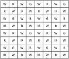
현 시점에서 가장 널리 사용되는 컬러 필터 어레이가 문헌 US-A-3971065 에 개시되어 있으며, 도 1에 도시한다.The most widely used color filter array at present is disclosed in document US-A-3971065 and is shown in Fig.
베이어 어레이(Bayer array)로 불리는 이 어레이는, 4개의 기본 필터들로 구성된 패턴의 주기적 반복에 의해 획득되며, 즉:This array, called a Bayer array, is obtained by a periodic repetition of the pattern consisting of four basic filters, namely:
여기서 ![]()
![]()
![]()
![]()
![]()
![]()
![]()
![]()
센서 내의 상이한 픽셀들에 의해 수신되는 강도(intensity)로 컬러 영상을 재구성하는 것으로 이루어지는 동작을 디모자이킹(demosaicking)이라 부른다. 이 디모자이킹 동작은 예를 들어, D. Alleyson 외 공저의 "Frequency selection demosaicking: a review and a look-ahead" 명칭의 문헌(Proc. of IS&T/SPIE VCIP, San Jose, CA, Jan. 2008에서 공개됨)에서 집중적으로 설명되어 있다.The operation of reconstructing the color image with the intensity received by the different pixels in the sensor is called demosaicking. This demosaicing operation is described, for example, in D. Alleyson et al., "Frequency selection demosaicking: a review and a look-ahead" (Proc. Of IS & T / SPIE VCIP, San Jose, Published).
낮은 조명 조건들 하에서 센서의 감도를 개선하기 위한 다른 컬러 필터 어레이들이 개시되어 있다. 이러한 어레이들의 대부분은 화이트 픽셀로 불리거나, 또는 투명한, 중간 또는 팬크로매틱(panchromatic) 픽셀로도 불리는 추가 픽셀들을 사용한다. 이들을 사용함으로써 색 신호(chrominance signal) 외에 조도 신호를 획득할 수가 있다. 이러한 어레이들의 예들이 출원 WO-A-2007/089416에 제공되어 있다.Other color filter arrays for improving the sensitivity of the sensor under low light conditions are disclosed. Most of these arrays use additional pixels, also called white pixels, or transparent, also called intermediate or panchromatic pixels. By using these, a luminance signal can be acquired in addition to a chrominance signal. Examples of such arrays are provided in application WO-A-2007/089416.
낮은 조명 조건들 하에서 양호한 감도를 획득하기 위해 자주 사용되는 필터 어레이는, 다음과 같은 기본 패턴에 의해 생성되는 소위 KodakTM 어레이이다:A filter array often used to obtain good sensitivity under low light conditions is the so-called Kodak TM array, which is produced by the following basic pattern:
여기서, 요소들 ![]()
![]()
![]()
![]()
낮은 조명 조건들 아래에서 센서 감도를 더욱 개선하기 위한 첫번째 간단한 해결방법은 근적외선 센서 응답을 사용하는 것이다. 그러나, 대부분의 영상 획득 장치들은 CCD 또는 CMOS 센서로부터 출력 잡음을 감소시키기 위해서, 입력부에 적외선 컷-오프 필터를 포함하고 있다. 첫째, 현 시점에서 자주 사용되는 기본 센서들은 실리콘으로 이루어져 있으며, 따라서 근적외선에 민감하고, 둘째, 상이한 픽셀들 전방에 배치된 기본 컬러 필터들은 스펙트럼의 적외선 일부를 효율적으로 차단할 수가 없다. The first simple solution to further improve sensor sensitivity under low lighting conditions is to use a near infrared sensor response. However, most image acquisition devices include an infrared cut-off filter at the input to reduce output noise from the CCD or CMOS sensor. First, the basic sensors frequently used at present are made of silicon, and therefore sensitive to near-infrared rays. Second, the primary color filters disposed in front of different pixels can not efficiently block some of the infrared rays of the spectrum.
문헌 JP-A-2010-062604은 컬러 픽셀들에 부가된 적외선 픽셀들의 사용을 개시하고 있으며, 여기서는 컬러 픽셀들이 주간 비전용으로 사용되고, 적외선 픽셀들은 야간 비전용으로 사용된다. 따라서, 이 경우에는 적외선 입력 필터에 의해 센서를 보호할 수가 없다. 센서가 주간 비전에서 동작하고 있는 경우에는 큰 노이즈가 발생하게 된다.Document JP-A-2010-062604 discloses the use of infrared pixels added to color pixels, in which color pixels are used for daytime use only, and infrared pixels are used for nighttime use only. Therefore, in this case, the sensor can not be protected by the infrared input filter. If the sensor is operating in daytime vision, large noise will occur.
본 발명의 목적은 양호한 신호-대-잡음 비율을 가지고 주간 비전 및 야간 비전에서 기능할 수 있는 영상 획득 시스템을 제공하는 것이다. It is an object of the present invention to provide an image acquisition system capable of functioning in day and night vision with a good signal-to-noise ratio.
본 발명은 픽셀들로 불리는 감광 요소들의 어레이로 구성되는 센서, 상기 센서를 덮으며 각각의 기본 필터가 대응 픽셀과 연관되는 기본 필터들의 어레이, 및 처리 수단을 포함하는 영상 획득 장치에 의해 규정된다.The invention is defined by an image acquisition device comprising a sensor consisting of an array of photosensitive elements called pixels, an array of basic filters covering the sensor, each basic filter associated with a corresponding pixel, and processing means.
이 장치는,The apparatus comprises:
- 상기 기본 필터들의 어레이는 하나의 프라이머리 컬러(primary colour)만을 통과시키는 프라이머리 컬러 필터들, 팬크로매틱 필터(panchromatic filter)들로 불리며 가시 스펙트럼(visible spectrum) 전체를 통과시키는 필터들, 및 근적외선을 통과시키는 적외선 필터(infrared filter)들을 포함하되, 상기 팬크로매틱 필터들은 상기 기본 필터들의 적어도 50%에 해당하고;The array of primary filters comprises primary color filters, which pass only one primary color, filters which pass through the entire visible spectrum, called panchromatic filters, and near infrared rays, Wherein the panchromatic filters correspond to at least 50% of the fundamental filters;
상기 처리 수단은,The processing means,
- 일련의 팬크로매틱 픽셀들에 대한 평균 조도를 계산하여, 적어도 하나의 센서 존(sensor zone)이 낮은 조명 조건들 아래에 있는지 또는 높은 조명 조건들 아래에 있는지를 결정하고;Calculating an average illuminance for a series of panchromatic pixels to determine if at least one sensor zone is below or under the high illumination conditions;
- 상기 존이 낮은 조명 조건들 아래에 있는 경우, 상기 팬크로매틱 픽셀들을 사용하여 상기 존의 단색 영상(monochrome image)을 형성하고;Forming a monochrome image of said zone using said panchromatic pixels if said zone is under low illumination conditions;
- 상기 존이 높은 조명 조건들 아래에 있는 경우, 프라이머리 컬러 픽셀들을 사용하여 상기 존의 컬러 영상을 형성하고, 적외선 픽셀들로부터 획득되는 상기 존으로부터의 적외선 영상을 제거하도록 설계된 것을 특징으로 한다.Characterized in that it is designed to form a color image of said zone using primary color pixels and to remove an infrared image from said zone obtained from infrared pixels when said zone is under high illumination conditions.
유리하게는, 상기 존의 단색 영상은 이 존의 일부를 형성하는 팬크로매틱 픽셀들의 보간에 의해 획득된다.Advantageously, the monochromatic image of the zone is obtained by interpolation of the panchromatic pixels forming part of the zone.
이와 유사하게, 상기 존의 컬러 영상은, 상기 존의 프라이머리 컬러 영상들의 조합에 의해 획득되며, 프라이머리 컬러 영상은 상기 존의 프라이머리 컬러 픽셀들의 보간에 의해 획득된다.Similarly, a color image of the zone is obtained by a combination of the primary color images of the zone, and a primary color image is obtained by interpolation of the primary color pixels of the zone.
마지막으로, 상기 존의 적외선 영상은 상기 존의 적외선 픽셀들의 보간에 의해 획득될 수 있다.Finally, the infrared image of the zone can be obtained by interpolation of the infrared pixels of the zone.
유리하게는, 팬크로매틱 필터들은 기본 필터들의 적어도 75%에 해당한다.Advantageously, the panchromatic filters correspond to at least 75% of the primary filters.
하나의 유리한 실시예에 따르면, 상기 기본 필터들의 어레이는 아래의 패턴의 2-차원의 주기적 반복에 의해 생성되며:According to one advantageous embodiment, the array of basic filters is generated by a two-dimensional periodic repetition of the following pattern:

여기서, ![]()
![]()
![]()
![]()
![]()
![]()
제 2 유리한 실시예에 따르면, 상기 기본 필터들의 어레이는 아래의 패턴의 2-차원의 주기적 반복에 의해 생성되며:According to a second advantageous embodiment, the array of basic filters is generated by a two-dimensional periodic repetition of the following pattern:

여기서, ![]()
![]()
![]()
![]()
![]()
![]()
![]()
![]()
제 3 유리한 실시예에 따르면, 상기 기본 필터들의 어레이는 아래의 패턴의 2-차원의 주기적 반복에 의해 생성되며:According to a third advantageous embodiment, the array of basic filters is generated by a two-dimensional periodic repetition of the following pattern:

여기서, ![]()
![]()
![]()
![]()
![]()
![]()
![]()
![]()
제 4 유리한 실시예에 따르면, 상기 기본 필터들의 어레이는 아래의 패턴의 2-차원의 주기적 반복에 의해 생성되며:According to a fourth advantageous embodiment, the array of basic filters is generated by a two-dimensional periodic repetition of the following pattern:
여기서, ![]()
![]()
![]()
![]()
![]()
![]()
![]()
![]()
바람직하게는, 상기 처리 수단은, 상기 존에서의 모든 팬크로매틱 픽셀들에 대한 평균 조도가 제 1 임계값보다 작은 경우에, 상기 존이 낮은 조명을 갖는 것으로 결정하고, 또한 상기 존에서의 모든 팬크로매틱 픽셀들에 대한 평균 조도가 제 2 임계값보다 큰 경우에는, 상기 존이 높은 조명을 갖는 것으로 결정하며, 상기 제 2 임계값은 상기 제 1 임계값보다 크다.Advantageously, the processing means determines that the zone has low illumination if the average illumination for all panchromatic pixels in the zone is less than a first threshold, and also determines that all the panchromatic pixels And the second threshold value is greater than the first threshold value when the average illuminance for the zones is greater than the second threshold value.
상기 존에서의 모든 팬크로매틱 픽셀들에 대한 평균 조도가 제 1 임계값과 제 2 임계값 사이에 있는 경우에는, 상기 처리 수단이 상기 존의 상기 컬러 영상과 상기 단색 영상의 조합을 행할 수 있다.The processing means may perform a combination of the color image and the monochromatic image in the zone when the average illuminance for all the panchromatic pixels in the zone is between the first threshold value and the second threshold value.
상기 센서 존은 상기 센서 전체이며, 상기 처리 수단은, 상기 센서가 낮은 조명 조명 조건들 아래에 있는지 또는 높은 조명 조건들 아래에 있는지를 결정한다.The sensor zone is the entire sensor, and the processing means determines whether the sensor is under low illumination conditions or under high illumination conditions.
대안적으로는, 상기 센서의 상기 단색 영상이 동종 영역(homogeneous region)들로 세그먼트화되고, 상기 처리 수단은 상기 센서의 각 동종의(homogeneous) 존 상에서 독립적으로 동작한다.Alternatively, the monochromatic image of the sensor is segmented into homogeneous regions, and the processing means operates independently on each homogeneous zone of the sensor.
본 발명의 다른 특징 및 장점은 첨부된 도면을 참조하여 본 발명의 바람직한 실시예의 설명을 읽은 이후에 명백해질 것이다.
도 1은 종래 기술에서 알려진 제 1 컬러 필터 어레이를 도식적으로 나타낸 것이다.
도 2는 종래 기술에서 알려진 제 2 컬러 필터 어레이를 도식적으로 나타낸 것이다.
도 3a는 본 발명의 제 1 예시적 실시예에 따른 예시적인 영상 획득 장치의 필터 어레이를 도식적으로 나타낸 것이다.
도 3b는 본 발명의 제 2 예시적 실시예에 따른 예시적인 영상 획득 장치의 필터 어레이를 도식적으로 나타낸 것이다.
도 4a는 본 발명의 제 3 예시적 실시예에 따른 영상 획득 장치의 예시적인 필터 어레이를 도식적으로 나타낸 것이다.
도 4b는 본 발명의 제 4 예시적 실시예에 따른 영상 획득 장치의 예시적인 필터 어레이를 도식적으로 나타낸 것이다.
도 5는 본 발명의 제 1 실시예에 따른 영상 획득 장치의 픽셀들에 대한 처리를 도식적으로 나타낸 것이다.
도 6은 본 발명의 제 2 실시예에 따른 영상 획득 장치의 픽셀들에 대한 처리를 도식적으로 나타낸 것이다. Other features and advantages of the present invention will become apparent after reading the description of the preferred embodiments of the present invention with reference to the accompanying drawings.
Figure 1 schematically depicts a first color filter array known in the art.
Figure 2 schematically illustrates a second color filter array known in the art.
3A schematically illustrates a filter array of an exemplary image acquisition device according to a first exemplary embodiment of the present invention.
Figure 3B schematically illustrates a filter array of an exemplary image acquisition device according to a second exemplary embodiment of the present invention.
4A schematically illustrates an exemplary filter array of an image acquisition device according to a third exemplary embodiment of the present invention.
Figure 4B schematically illustrates an exemplary filter array of an image acquisition device according to a fourth exemplary embodiment of the present invention.
5 is a graphical representation of processing for pixels of an image acquisition apparatus according to the first embodiment of the present invention.
6 is a diagram schematically illustrating a process for pixels of an image capturing apparatus according to a second embodiment of the present invention.
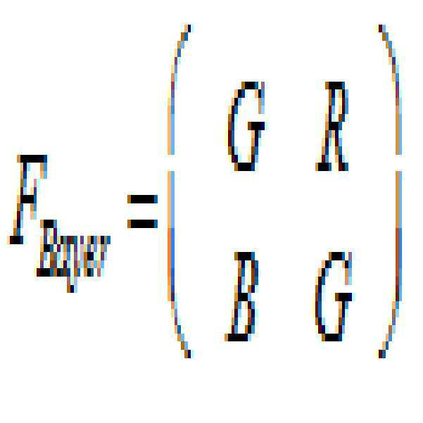
픽셀들로도 불리는 기본 감광 센서들(CCD 또는 CMOS)의 어레이로 구성된 센서, 및 이 센서들을 덮으며 각 기본 필터가 일 픽셀과 연관되는 기본 필터 어레이를 포함하는 다음의 영상 획득 장치에 대해 다시 한번 고찰해 보도록 한다. 더욱 정확하게는, 각 기본 필터는 연관 픽셀에 대한 입사광을 필터링한다. Consider again the following image acquisition device comprising a sensor consisting of an array of primary photosensors (CCD or CMOS), also referred to as pixels, and a basic filter array covering each of these sensors, with each primary filter being associated with one pixel See you. More precisely, each basic filter filters the incident light for the associated pixel.
어레이 내의 기본 필터들은 다음과 같은 3개의 상이한 타입의 송신 필터들이다: 컬러 필터들, 투명 (또는 팬크로매틱) 필터들 및 적외선 필터들. The basic filters in the array are three different types of transmit filters: color filters, transparent (or panchromatic) filters, and infrared filters.
컬러 기본 필터들은 일련의 프라이머리 컬러(primary colour)들이 통과될 수 있게 함으로써, 가시 스펙트럼에 있어서의 모든 컬러들의 가산 합성 또는 감산 합성을 가능하게 한다. 따라서, 가산 합성의 경우에, 컬러 필터들은 서두에서 정의된 바와 같은 ![]()
![]()
![]()
![]()
![]()
![]()
![]()
![]()
![]()
![]()
팬크로매틱 기본 필터들은 가시 스펙트럼 전체가 통과할 수 있게 한다. 실제에 있어서, 이것들은 (눈에 보이는) 어레이 내의 단순 스텐실들 또는 투명 필터들로 이루어질 수 있다. 이 경우, 이러한 팬크로매틱 기본 필터들 아래에 위치된 픽셀들은 필터링되지 않은 광을 수신한다. Panchromatic base filters allow the entire visible spectrum to pass. In practice, these may consist of simple stencils or transparent filters in the (visible) array. In this case, the pixels located under these panchromatic fundamental filters receive the unfiltered light.
적외선의 기본 필터들은 근적외선에서의 스펙트럼 대역이, 예를 들어, [700nm-1700nm] 대역에서만, 또한 보다 구체적으로는, [700nm-1100nm] 대역에서만 통과될 수 있게 한다.Infrared basic filters allow the spectral bands in the near-infrared to pass only in the [700nm-1700nm] band, and more specifically in the [700nm-1100nm] band, for example.
유리하게는, 기본 필터들은 센서의 평면에서 두 개의 다른 방향(일반적으로는 직교)을 따르는 주기적 반복 패턴의 형태로 배열된다.Advantageously, the base filters are arranged in the form of periodic repeating patterns along two different directions (generally orthogonal) in the plane of the sensor.
기본 필터들은 폴리머 재료로 형성될 수 있으며, 또는 그 자체가 공지된 방식의 간섭 필터들일 수 있다. The base filters may be formed of a polymeric material, or may be interference filters in a manner known per se.
바람직하게는, 어레이 내의 팬크로매틱 기본 필터의 비율은 50% 이상이 되며, 다른 기본 필터들(컬러 필터들 및 적외선 필터들)이 동일한 비율들로 분포된다. 유리하게는, 팬크로매틱 기본 필터들의 비율은 75%가 되며, 다른 기본 필터들 각각의 비율은 6.25%가 된다.Preferably, the ratio of the panchromatic base filter in the array is greater than 50%, and the other base filters (color filters and infrared filters) are distributed in equal proportions. Advantageously, the ratio of the panchromatic base filters is 75%, and the ratio of each of the other base filters is 6.25%.
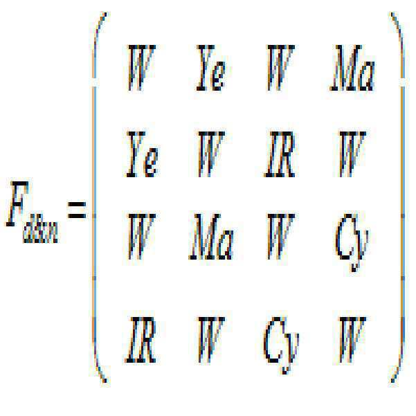
도 3a는 본 발명의 제 1 예시적 실시예에 따른 영상 획득 시스템의 기본 필터들의 어레이를 도시한 것이다. 각 기본 필터마다 하나의 센서 픽셀이 존재한다. 3A shows an array of basic filters of an image acquisition system according to a first exemplary embodiment of the present invention. There is one sensor pixel for each basic filter.
이 경우에 있어서, 컬러 기본 필터들은 ![]()
![]()
![]()
![]()
![]()
![]()
기본 어레이는 기본 4X4 패턴을 갖는 2-차원의 주기적 반복에 의해 생성됨에 유의한다: Note that the basic array is created by a two-dimensional periodic iteration with a basic 4X4 pattern:

이 어레이의 변형들은 패턴 (3)에 있어서의 ![]()
![]()
도 3b는 본 발명의 제 2 예시적 실시예에 따른 영상 획득 시스템의 기본 필터들의 어레이를 도시한 것이다. Figure 3B shows an array of basic filters of an image acquisition system according to a second exemplary embodiment of the present invention.
이 경우에 있어서는, 컬러 기본 필터들이 ![]()
![]()

제 1 예에서와 같이, 이 어레이의 변형들은 어레이 (4)에 있어서의 ![]()
![]()
도 3a 및 3b의 예들에서는, 어레이 내의 팬크로매틱 필터들의 비율이 75%이고, 각 컬러 및 적외선 필터의 비율은 6.25%임에 유의한다. Note that in the examples of Figures 3a and 3b, the ratio of panchromatic filters in the array is 75%, and the ratio of each color and infrared filter is 6.25%.
도 4a는 본 발명의 제 3 예시적 실시예에 따른 영상 획득 시스템의 기본 필터 어레이를 도시한 것이다. 4A illustrates a basic filter array of an image acquisition system according to a third exemplary embodiment of the present invention.
어레이에 사용된 기본 필터들은 ![]()
![]()

제 1 예에서와 같이, 이 어레이의 변형들은 패턴 (5)에 있어서의 ![]()
![]()
도 4b는 본 발명의 제 4 예시적 실시예에 따른 영상 획득 시스템의 기본 필터 어레이를 도시한 것이다. Figure 4b illustrates a basic filter array of an image acquisition system according to a fourth exemplary embodiment of the present invention.
어레이를 구성하는 기본 필터들은 ![]()
![]()

제 2 예에서와 같이, 이 어레이의 변형들은 패턴 (6)에 있어서의 ![]()
![]()
도 4a 및 4b의 예들에서는, 어레이 내의 팬크로매틱 필터들의 비율이 단지 50%이며, 각 컬러 및 적외선 필터의 비율은 12.5%임에 유의한다. Note that in the examples of Figures 4A and 4B, the ratio of panchromatic filters in the array is only 50%, and the ratio of each color and infrared filter is 12.5%.
도 5는 본 발명의 제 1 실시예에 따른 영상 획득 시스템에 있어서의 픽셀들의 처리를 도식적으로 나타낸 것이다. 5 schematically illustrates processing of pixels in an image acquisition system according to the first embodiment of the present invention.
이하에서는, 픽셀들의 동작을, 이러한 픽셀들에 의해 수신되는 신호들에 대한 동작으로서 이해할 것이다. In the following, the operation of the pixels will be understood as an operation on the signals received by these pixels.
제 1 단계(510)에서, 장치에 의해 획득되는 영상의 평균 조도 ![]()
![]()
단계(520)에서는, 이렇게 획득된 평균이, 미리 결정된 임계값 ![]()
![]()
획득 장치가 주간 모드로 동작하고 있는 경우, 단계(530)에서 컬러 픽셀들이 보간됨으로써, 각 프라이머리 컬러 ![]()
![]()
![]()
![]()
선택적으로는, 프라이머리 컬러 영상들이 영상 선명화를 위해 처리될 수도 있다. 예를 들어, 단색 영상은 팬크로매틱 픽셀들을 보간함으로써 획득될 수 있으며, 이 단색 영상은, 가능하게는 하이 패스 필터링 이후에, 각 프라이머리 컬러 영상과 조합될 수 있다. 어레이 내의 팬크로매틱 픽셀들의 비율은 컬러 픽셀들의 비율보다 높으며, 따라서 프라이머리 컬러 영상들의 해상도가 개선된다. Alternatively, the primary color images may be processed for image sharpening. For example, a monochromatic image may be obtained by interpolating panchromatic pixels, which may be combined with each primary color image, possibly after high pass filtering. The ratio of the panchromatic pixels in the array is higher than the ratio of the color pixels, thus improving the resolution of the primary color images.
단계(540)에서는, 근적외선에서의 영상이, 컬러 픽셀들에 대해 전술한 바와 같은 원리를 사용하여 어레이에 내의 적외선 픽셀들 간의 보간에 의해 획득된다. In
단계(550)에서는, 프라이머리 컬러 영상들이 (가산 합성을 위해) 부가되어 컬러 영상을 획득하게 되며, 또한 픽셀 바이 픽셀로 적외선 영상이 그로부터 제거된다. 보다 일반적으로는, 프라이머리 컬러 영상들이 조합되어 컬러 영상을 획득하게 된다. 적외선 영상의 제거는 신호 대 잡음비를 상당히 개선할 수 있다. 필요한 경우에는, (유사한 또는 동일한) 가중 요소들에 의해 가중처리되는 적외선 영상이 각 프라이머리 컬러 영상으로부터 제거됨으로써, 이들을 합하기(또는 보다 일반적으로는 이들을 조합) 이전에 잡음 없는 프라이머리 컬러 영상들을 획득하게 되며, 이에 따라 포화(saturation) 문제들을 방지하도록 한다. 그 후에, 이 결과 영상이 디스플레이될 수 있으며, 또는 후속 처리를 위하여 메모리에 저장될 수도 있다. In
단계(560)는 야간 모드에서의(또는 낮은 조명 하의) 동작에 대응한다. Step 560 corresponds to an operation in night mode (or under low illumination).
이 모드에서는, 단색 영상이 팬크로매틱 픽셀들의 보간에 의해 획득된다. 어레이 내에는 다수의 팬크로매틱 픽셀들이 존재하기 때문에, 높은 수준의 해상도가 획득된다. 이러한 영상이 디스플레이될 수 있으며, 또는 후속 처리를 위하여 메모리에 저장될 수도 있다. In this mode, a monochrome image is obtained by interpolation of the panchromatic pixels. Because there are a number of panchromatic pixels within the array, a high level of resolution is obtained. Such an image may be displayed or may be stored in memory for further processing.
모든 경우들에 있어서, 처리는 단계(570)에서 종료된다. In all cases, processing ends at
전술한 픽셀들의 처리는, 영상 획득 장치가 주간 모드 또는 야간 모드에서 동작하고 있는 경우에 매우 상이하며, 평균 조도를 미리 결정된 임계값과 비교하는 것에 의해서, 하나의 모두로부터 다른 모드로의 스위칭이 이루어지게 된다는 것이 이해될 수 있다. The processing of the pixels described above is very different when the image acquisition device is operating in a daytime mode or a nighttime mode and switching from one all to another mode is made by comparing the average illumination with a predetermined threshold value It can be understood that it is lost.
이 실시예에 대한 하나의 제 1 변형예에 따르면, 하나의 모드로부터 다른 모드로의 스위칭이 히스테리시스(hysteresis)와 함께 발생함으로써 스위칭 잡음(채터링(chattering))을 방지하게 된다. 이를 달성하기 위해, 주간 모드로부터 야간 모드로의 전환을 위한 제 1 조도 임계값이 설정되고, 야간 모드로부터 주간 모드로의 전환을 위한 제 2 조도 임계값이 설정되며, 제 1 임계값은 제 2 임계값보다 작도록 선택된다. According to one first modification of this embodiment, switching from one mode to another mode occurs with hysteresis to prevent switching noise (chattering). To achieve this, a first illumination threshold for switching from day mode to night mode is set, a second illumination threshold for switching from night mode to day mode is set, and a first threshold is set for the second Is selected to be smaller than the threshold value.
제 1 실시예의 제 2 변형예에 따르면, 하나의 모드로부터 다른 모드로의 스위칭은, 전환 단계를 점진적으로 거치면서 발생하게 된다. 이에 따라, 영상 획득 장치는, 평균 조도가 제 1 임계값보다 작은 경우에 야간 모드에서 동작하고, 평균 조도가 제 2 임계값보다 큰 경우에는 야간 모드에서 동작하며, 제 2 임계값은 제 1 임계값보다 높도록 선택된다. 평균 조도가 제 1 임계값과 제 2 임계값 사이에 존재하는 경우, 영상 획득 장치는 주간 모드에서의 처리에 의해 획득되고 또한 야간 모드에서의 처리에 의해 획득되는 영상의 선형 조합을 수행하며, 제 1 및 제 2 임계값들을 각기 가진 평균 조도의 차분만큼 가중 계수들이 제공된다.According to the second variant of the first embodiment, switching from one mode to another occurs as the switching step progressively passes. Accordingly, the image acquiring device operates in the night mode when the average illuminance is smaller than the first threshold, and operates in the night mode when the average illuminance is larger than the second threshold, and the second threshold operates in the first threshold Value. When the average illuminance is between the first threshold value and the second threshold value, the image acquiring device performs a linear combination of the images obtained by the processing in the daytime mode and obtained by the processing in the nighttime mode, 1 < / RTI > and second threshold values.
도 6은 본 발명의 제 2 실시예에 따른 영상 획득 장치에 있어서의 픽셀들의 처리를 도식적으로 나타낸 것이다. FIG. 6 schematically shows the processing of pixels in the image capturing apparatus according to the second embodiment of the present invention.
제 1 실시예와 달리, 주간 모드(또는 높은 조명)와 야간 모드(낮은 조명) 간의 스위칭은 획득되는 영상의 동종 영역(homogeneous region)들 상에서 활성화되며, 각 동종 영역은 개별적으로 처리된다. Unlike the first embodiment, the switching between the daytime mode (or high illumination) and the nighttime mode (low illumination) is activated on homogeneous regions of the acquired image, and each homogeneous region is processed individually.
단계(603)에서는, 팬크로매틱 픽셀들을 보간함으로써 단색 영상이 획득된다. 보다 정확하게는, 어레이에서의 각 누락된 팬크로매틱 픽셀에 대한(예를 들어, 컬러 또는 적외선 픽셀), 강도(intensity)는 근처 팬크로매틱 픽셀들로부터 계산된다. In
단계(605)에서는, 이에 따라 단색 영상이 동종 영역들로 세그먼트화된다. 이것은 예를 들어, Tripathi 외 공저의 "Image Segmentation : a review" 명칭의 문헌(International Journal of Computer Science and Management Research, vol. 1, No. 4, Nov. 2012, pp. 838-843에서 공개됨)에서 기술된 바와 같은 종래에 알려진 스위칭 기술을 사용하여 행해질 수 있다. 이에 따라, 결과적으로 ![]()
![]()
단계(610)에서는, ![]()
![]()
![]()
![]()
![]()
![]()
단계(620)에서는, 이렇게 획득된 조도의 평균들이 미리 결정된 임계값과 비교된다. 평균 ![]()
![]()
![]()
![]()
![]()
![]()
![]()
![]()
주어진 존(zone)에 대한, 낮은 조명와 높은 조명 간의 구별은 팬크로매틱 픽셀들로부터 획득되는 조도의 평균에 따라 달라짐에 유의한다. 즉, 평균 조도는 전체 스펙트럼 상에서 획득된다. Note that the distinction between low and high illumination for a given zone depends on the average of the illumination obtained from the panchromatic pixels. That is, the average roughness is obtained over the entire spectrum.
단계(630)에서는, 높은 조명을 가진 영역들이 처리된다. 각 높은 조명 영역의 경우, 이 영역에 속해 있는 컬러 픽셀들이 보간됨으로써, 각 프라이머리 컬러 ![]()
![]()
![]()
![]()
단계(640)에서는, 각 높은 조명 영역에 속해 있는 적외선 픽셀들을 보간함으로써, 이 영역의 근적외선에서의 영상이 획득된다. In
단계(650)에서는, 각 높은 조명 영역마다 프라이머리 컬러 영상들이 조합되며(가산 합성의 경우 간단한 합산), 적외선 영상이 픽셀 바이 픽셀로 제외된다. 이에 따라, 결과적으로 각 높은 조명 영역마다 컬러 영상을 형성하는 컬러 픽셀들이 획득된다.In
단계(660)에서는, 단계(603)에서 획득되는 단색 영상에 있어서의 높은 조명 영역들의 팬크로매틱 픽셀들이, 단계(650)에서 획득되는 컬러 픽셀들에 의해 대체된다. 대안적으로는, 팬크로매틱 픽셀(즉, 단색 영상에 있어서의 픽셀)과 단계(650)에서 획득되는 컬러 픽셀의 선형 조합이, 높은 조명 영역에 속해 있는 각각의 픽셀마다 이루어진다. 따라서, 낮은 조명 영역들의 경우, (단계(603)에서 획득되는) 단색 영상은 (단계(650)에서 획득되는) 컬러 영상과 중첩된다. In
제 1 실시예에서와 같이, 제 1 변형예에서는, 두 개의 별개의 임계값, 즉 영역이 낮은 조명 레벨로부터 높은 조명 레벨로 변경되는 경우를 검출하는 제 1 임계값, 및 영역이 높은 조명 레벨로부터 낮은 조명 레벨로 변경되는 경우를 결정하는 제 2 임계값이 사용될 수 있으며, 여기서 제 1 임계값은 제 2 임계값보다 작다. As in the first embodiment, in the first modification, two distinct thresholds, i.e., a first threshold value for detecting when a region is changed from a low illumination level to a high illumination level, A second threshold value may be used to determine when to change to a lower illumination level, wherein the first threshold value is less than the second threshold value.
두 개의 임계값 사이에 과도 단계를 사용하는 것이 또한 제 2 변형예에서 가능하다. 즉, 제 1 임계값 미만의 영역은 팬크로매틱 픽셀들의 보간에 의해 단색 모드로 나타내지고, 제 2 임계값 초과의 영역은 컬러로 나타내지며, 두 개의 임계값 사이의 영역은 단색 영상 및 컬러 영상의 선형 조합에 의해 나타내질 수도 있다.It is also possible in the second variant to use transient steps between the two threshold values. That is, an area below the first threshold value is represented by a monochrome mode by interpolation of the panchromatic pixels, an area above the second threshold value is represented by color, and an area between the two threshold values is represented by a linear May be represented by a combination.
따라서, 매우 양호한 신호 대 잡음비를 가지면서, 조명 조건들에 관계없이 기능할 수 있는 영상 획득 장치가 있게됨을 이해할 수 있다. Thus, it will be appreciated that there will be an image acquisition device capable of functioning independently of the illumination conditions, with a very good signal-to-noise ratio.
제 2 실시예에 나타내지 않은 다른 변형예에 따르면, 어떤 존(zone)이 낮은 조명을 갖는 것으로 테스트(620)가 결정한 경우에는, 이 존의 일부를 형성하는 적외선 픽셀들의 강도가 미리 결정된 IR 임계값보다 큰지 여부가 결정된다. 이어서, 그 강도가 IR 임계값보다 큰 적외선 픽셀들은, 그 존의 단색 영상과 중첩되는 위색(false colour)으로 표현된다. 따라서, 낮은 조명 존의 서브-존이 적외선 영역에서 높은 강도를 갖는 경우, 그것은 해당 존의 단색 영상에서 용이하게 식별될 수 있다. 또한 대안적으로, 단색 디스플레이와 위색들에서의 디스플레이 간의 스위칭을 위한 기준은, 낮은 조명 존의 동종 서브-존들에 의해 이루어질 수 있다. 이 경우에 있어서, 낮은 조명 존은, 단계들(603 및 605)과 관련하여 설명된 것과 동일한 원리를 사용하여, 보간 이후, 적외선 픽셀들에 기초하여 먼저 세그먼트화된다. 위에서 규정된 각 동종 서브-존마다에 대하여, 이 서브-존에 있어서의 적외선 픽셀들의 평균 강도가 계산되어 전술한 IR 임계값과 비교된다. 이 평균이 IR 임계값보다 큰 경우에는, 서브-존이 그 존의 단색 영상 위에 중첩되는 위색들로 표현된다. 위색들에 있어서의 서브-존의 영상은 이 서브-존에서의 적외선 픽셀들의 보간에 의해 획득된다. 따라서, 이 경우, 기본 컬러 픽셀들(RGB 또는 Cyan, Magenta, Yellow)을 제외한 팬크로매틱 픽셀들(단색 일부)과 적외선 픽셀들(위색들의 일부)의 조합에 의해서, 낮은 조명 존이지만 높은 적외선 강도를 가진 서브-존들의 영상이 획득됨이 이해될 것이다.According to another variant not shown in the second embodiment, when a
Claims (18)
- 상기 기본 필터들의 어레이는 하나의 프라이머리 컬러(primary colour)만을 통과시키는 프라이머리 컬러 필터들, 팬크로매틱 필터(panchromatic filter)들로 불리며 가시 스펙트럼(visible spectrum) 전체를 통과시키는 필터들, 및 근적외선을 통과시키는 적외선 필터(infrared filter)들을 포함하되, 상기 팬크로매틱 필터들은 상기 기본 필터들의 적어도 50%에 해당하고;
상기 처리 수단은,
- 일련의 팬크로매틱 픽셀들에 대한 평균 조도를 계산하여, 적어도 하나의 센서 존(sensor zone)이 낮은 조명 조건들 아래에 있는지 또는 높은 조명 조건들 아래에 있는지를 결정하고;
- 상기 존이 낮은 조명 조건들 아래에 있는 경우, 상기 팬크로매틱 픽셀들을 사용하여 상기 존의 단색 영상(monochrome image)을 형성하고;
- 상기 존이 높은 조명 조건들 아래에 있는 경우, 프라이머리 컬러 픽셀들을 사용하여 상기 존의 컬러 영상을 형성하고, 적외선 픽셀들로부터 획득되는 상기 존으로부터의 적외선 영상을 제거하도록 설계된 것을 특징으로 하는 영상 획득 장치.An image acquisition device comprising a sensor comprised of an array of photosensitive elements called pixels, an array of basic filters each of which is associated with a corresponding pixel, and processing means,
The array of primary filters comprises primary color filters that pass only one primary color, filters that pass the entire visible spectrum, called panchromatic filters, and near infrared Wherein the panchromatic filters correspond to at least 50% of the fundamental filters;
The processing means,
Calculating an average illuminance for a series of panchromatic pixels to determine if at least one sensor zone is below or under the high illumination conditions;
Forming a monochrome image of said zone using said panchromatic pixels if said zone is under low illumination conditions;
Characterized in that it is designed to form a color image of said zone using primary color pixels and to remove an infrared image from said zone obtained from infrared pixels when said zone is under high illumination conditions Acquisition device.

여기서,
here,

여기서,
here,

여기서,
here,

여기서,
here,
상기 적외선 필터들은 700nm-1100nm 대역을 투과시키는 것을 특징으로 하는 영상 획득 장치.17. The method according to any one of claims 1 to 16,
Wherein the infrared filters transmit the 700nm-1100nm band.
Applications Claiming Priority (3)
| Application Number | Priority Date | Filing Date | Title |
|---|---|---|---|
| FR1353482 | 2013-04-17 | ||
| FR1353482A FR3004882B1 (en) | 2013-04-17 | 2013-04-17 | DEVICE FOR ACQUIRING BIMODE IMAGES |
| PCT/EP2014/057698 WO2014170359A1 (en) | 2013-04-17 | 2014-04-16 | Device for acquiring bimodal images |
Publications (2)
| Publication Number | Publication Date |
|---|---|
| KR20150140832A true KR20150140832A (en) | 2015-12-16 |
| KR102170410B1 KR102170410B1 (en) | 2020-10-28 |
Family
ID=48979925
Family Applications (1)
| Application Number | Title | Priority Date | Filing Date |
|---|---|---|---|
| KR1020157032475A KR102170410B1 (en) | 2013-04-17 | 2014-04-16 | Device for acquiring bimodal images |
Country Status (11)
| Country | Link |
|---|---|
| US (1) | US9736437B2 (en) |
| EP (1) | EP2987321B1 (en) |
| JP (1) | JP6492055B2 (en) |
| KR (1) | KR102170410B1 (en) |
| CN (1) | CN105210369B (en) |
| CA (1) | CA2909554C (en) |
| FR (1) | FR3004882B1 (en) |
| IL (1) | IL242097B (en) |
| SG (1) | SG11201508579VA (en) |
| TW (1) | TWI669963B (en) |
| WO (1) | WO2014170359A1 (en) |
Cited By (1)
| Publication number | Priority date | Publication date | Assignee | Title |
|---|---|---|---|---|
| WO2023085533A1 (en) * | 2021-11-15 | 2023-05-19 | 주식회사 넥스트칩 | Method for generating image having infrared information removed, and electronic device performing method |
Families Citing this family (26)
| Publication number | Priority date | Publication date | Assignee | Title |
|---|---|---|---|---|
| US9692992B2 (en) | 2013-07-01 | 2017-06-27 | Omnivision Technologies, Inc. | Color and infrared filter array patterns to reduce color aliasing |
| US9667933B2 (en) * | 2013-07-01 | 2017-05-30 | Omnivision Technologies, Inc. | Color and infrared filter array patterns to reduce color aliasing |
| DE102013223699A1 (en) * | 2013-11-20 | 2015-05-21 | Takata AG | Filter assembly and method of making a filter assembly |
| CN108769502B (en) * | 2014-06-24 | 2020-10-30 | 麦克赛尔株式会社 | Image pickup processing apparatus and image pickup processing method |
| FR3026223B1 (en) * | 2014-09-22 | 2016-12-23 | Photonis France | APPARATUS FOR ACQUIRING PHOTOCATHODE BIMODE IMAGES. |
| TWI577971B (en) * | 2015-10-22 | 2017-04-11 | 原相科技股份有限公司 | Dual-aperture ranging system |
| FR3045263B1 (en) * | 2015-12-11 | 2017-12-08 | Thales Sa | SYSTEM AND METHOD FOR ACQUIRING VISIBLE AND NEAR INFRARED IMAGES USING A SINGLE MATRIX SENSOR |
| CN106878690A (en) * | 2015-12-14 | 2017-06-20 | 比亚迪股份有限公司 | The imaging method of imageing sensor, imaging device and electronic equipment |
| FR3048800B1 (en) * | 2016-03-11 | 2018-04-06 | Bertin Technologies | IMAGE PROCESSING METHOD |
| US10574909B2 (en) | 2016-08-08 | 2020-02-25 | Microsoft Technology Licensing, Llc | Hybrid imaging sensor for structured light object capture |
| CN107786857B (en) * | 2016-08-25 | 2019-07-19 | 杭州海康威视数字技术股份有限公司 | A kind of image restoring method and device |
| CN108419061B (en) * | 2017-02-10 | 2020-10-02 | 杭州海康威视数字技术股份有限公司 | Multispectral-based image fusion equipment and method and image sensor |
| US9986128B1 (en) * | 2017-03-10 | 2018-05-29 | Kabushiki Kaisha Toshiba | Image forming apparatus and image forming method facilitating processing color |
| CN106911919A (en) * | 2017-03-24 | 2017-06-30 | 陈兵 | Color image sensor and coloured image imaging method |
| CN106713878A (en) * | 2017-03-24 | 2017-05-24 | 陈兵 | Novel image sensor |
| WO2018183206A1 (en) | 2017-03-26 | 2018-10-04 | Apple, Inc. | Enhancing spatial resolution in a stereo camera imaging system |
| CN107370917B (en) * | 2017-06-30 | 2020-01-10 | Oppo广东移动通信有限公司 | Control method, electronic device, and computer-readable storage medium |
| CN109327665A (en) * | 2017-07-26 | 2019-02-12 | 聚晶半导体股份有限公司 | Image acquiring device and its infrared sensing method |
| CN109756713B (en) * | 2017-11-08 | 2021-12-21 | 超威半导体公司 | Image capturing apparatus, method of performing processing, and computer readable medium |
| CN110493583B (en) * | 2018-08-03 | 2021-12-17 | 杭州海康威视数字技术股份有限公司 | Image processing method, image processing device, electronic equipment and computer readable storage medium |
| CN109905681B (en) * | 2019-02-01 | 2021-07-16 | 华为技术有限公司 | Image sensor, method of acquiring image data therefrom, and image pickup apparatus |
| CN111447380B (en) * | 2020-05-22 | 2022-03-22 | Oppo广东移动通信有限公司 | Control method, camera assembly and mobile terminal |
| US20220303515A1 (en) * | 2021-03-17 | 2022-09-22 | Mediatek Inc. | High Sensitivity Color Image Generation Using Hybrid Sensor |
| CN113418864B (en) * | 2021-06-03 | 2022-09-16 | 奥比中光科技集团股份有限公司 | Multispectral image sensor and manufacturing method thereof |
| CN113660415A (en) * | 2021-08-09 | 2021-11-16 | Oppo广东移动通信有限公司 | Focus control method, device, imaging apparatus, electronic apparatus, and computer-readable storage medium |
| CN113676617B (en) * | 2021-08-12 | 2023-08-18 | Oppo广东移动通信有限公司 | Motion detection method, motion detection device, electronic device and computer-readable storage medium |
Citations (6)
| Publication number | Priority date | Publication date | Assignee | Title |
|---|---|---|---|---|
| JP2001045512A (en) * | 1999-08-04 | 2001-02-16 | Sanyo Electric Co Ltd | Black.white/color switching camera |
| JP2005525052A (en) * | 2002-05-08 | 2005-08-18 | ボール エアロスペース アンド テクノロジーズ コーポレイション | Single chip low light level color camera |
| JP2006148690A (en) * | 2004-11-22 | 2006-06-08 | Toyota Central Res & Dev Lab Inc | Imaging device |
| JP2007053731A (en) * | 2005-07-21 | 2007-03-01 | Sony Corp | Physical information acquisition method, physical information acquiring apparatus, and semiconductor apparatus |
| JP2010512049A (en) * | 2006-11-30 | 2010-04-15 | イーストマン コダック カンパニー | Processing images with color and panchromatic pixels |
| JP2011259060A (en) * | 2010-06-07 | 2011-12-22 | Konica Minolta Opto Inc | Image pickup device |
Family Cites Families (20)
| Publication number | Priority date | Publication date | Assignee | Title |
|---|---|---|---|---|
| US3971065A (en) | 1975-03-05 | 1976-07-20 | Eastman Kodak Company | Color imaging array |
| US6211521B1 (en) * | 1998-03-13 | 2001-04-03 | Intel Corporation | Infrared pixel sensor and infrared signal correction |
| US5914749A (en) * | 1998-03-31 | 1999-06-22 | Intel Corporation | Magenta-white-yellow (MWY) color system for digital image sensor applications |
| US20040174446A1 (en) * | 2003-02-28 | 2004-09-09 | Tinku Acharya | Four-color mosaic pattern for depth and image capture |
| US7477304B2 (en) * | 2004-08-26 | 2009-01-13 | Micron Technology, Inc. | Two narrow band and one wide band color filter for increasing color image sensor sensitivity |
| US7688368B2 (en) | 2006-01-27 | 2010-03-30 | Eastman Kodak Company | Image sensor with improved light sensitivity |
| KR101276757B1 (en) * | 2006-05-26 | 2013-06-20 | 삼성전자주식회사 | Apparatus for photographing image and operating method for the same |
| KR20070115243A (en) * | 2006-06-01 | 2007-12-05 | 삼성전자주식회사 | Apparatus for photographing image and operating method for the same |
| JP5106870B2 (en) * | 2006-06-14 | 2012-12-26 | 株式会社東芝 | Solid-state image sensor |
| US8031243B2 (en) * | 2007-07-06 | 2011-10-04 | Samsung Electronics Co., Ltd. | Apparatus, method, and medium for generating image |
| US8446470B2 (en) * | 2007-10-04 | 2013-05-21 | Magna Electronics, Inc. | Combined RGB and IR imaging sensor |
| US20090159799A1 (en) * | 2007-12-19 | 2009-06-25 | Spectral Instruments, Inc. | Color infrared light sensor, camera, and method for capturing images |
| JP2009253447A (en) * | 2008-04-02 | 2009-10-29 | Panasonic Corp | Solid state image sensor for both near-infrared light and visible light, and solid-state imaging apparatus |
| JP4618342B2 (en) * | 2008-05-20 | 2011-01-26 | 日本テキサス・インスツルメンツ株式会社 | Solid-state imaging device |
| JP2010062604A (en) | 2008-09-01 | 2010-03-18 | Rohm Co Ltd | Imaging sensor |
| US8203633B2 (en) * | 2009-05-27 | 2012-06-19 | Omnivision Technologies, Inc. | Four-channel color filter array pattern |
| KR101739880B1 (en) * | 2010-12-01 | 2017-05-26 | 삼성전자주식회사 | Color filter array, image sensor having the same, and image processing system having the same |
| CN102957917B (en) * | 2011-08-30 | 2016-03-30 | 比亚迪股份有限公司 | A kind of pel array, camera and the color processing method based on this array |
| US9191635B2 (en) * | 2012-03-19 | 2015-11-17 | Semiconductor Components Industries, Llc | Imaging systems with clear filter pixels |
| US9231015B2 (en) * | 2012-09-24 | 2016-01-05 | Omnivision Technologies, Inc. | Backside-illuminated photosensor array with white, yellow and red-sensitive elements |
-
2013
- 2013-04-17 FR FR1353482A patent/FR3004882B1/en active Active
-
2014
- 2014-04-16 WO PCT/EP2014/057698 patent/WO2014170359A1/en active Application Filing
- 2014-04-16 KR KR1020157032475A patent/KR102170410B1/en active IP Right Grant
- 2014-04-16 TW TW103113899A patent/TWI669963B/en active
- 2014-04-16 EP EP14718066.5A patent/EP2987321B1/en active Active
- 2014-04-16 JP JP2016508143A patent/JP6492055B2/en active Active
- 2014-04-16 CN CN201480025311.1A patent/CN105210369B/en active Active
- 2014-04-16 US US14/785,037 patent/US9736437B2/en active Active
- 2014-04-16 CA CA2909554A patent/CA2909554C/en active Active
- 2014-04-16 SG SG11201508579VA patent/SG11201508579VA/en unknown
-
2015
- 2015-10-15 IL IL242097A patent/IL242097B/en active IP Right Grant
Patent Citations (6)
| Publication number | Priority date | Publication date | Assignee | Title |
|---|---|---|---|---|
| JP2001045512A (en) * | 1999-08-04 | 2001-02-16 | Sanyo Electric Co Ltd | Black.white/color switching camera |
| JP2005525052A (en) * | 2002-05-08 | 2005-08-18 | ボール エアロスペース アンド テクノロジーズ コーポレイション | Single chip low light level color camera |
| JP2006148690A (en) * | 2004-11-22 | 2006-06-08 | Toyota Central Res & Dev Lab Inc | Imaging device |
| JP2007053731A (en) * | 2005-07-21 | 2007-03-01 | Sony Corp | Physical information acquisition method, physical information acquiring apparatus, and semiconductor apparatus |
| JP2010512049A (en) * | 2006-11-30 | 2010-04-15 | イーストマン コダック カンパニー | Processing images with color and panchromatic pixels |
| JP2011259060A (en) * | 2010-06-07 | 2011-12-22 | Konica Minolta Opto Inc | Image pickup device |
Cited By (1)
| Publication number | Priority date | Publication date | Assignee | Title |
|---|---|---|---|---|
| WO2023085533A1 (en) * | 2021-11-15 | 2023-05-19 | 주식회사 넥스트칩 | Method for generating image having infrared information removed, and electronic device performing method |
Also Published As
| Publication number | Publication date |
|---|---|
| SG11201508579VA (en) | 2015-11-27 |
| TWI669963B (en) | 2019-08-21 |
| FR3004882B1 (en) | 2015-05-15 |
| CN105210369B (en) | 2017-06-27 |
| US9736437B2 (en) | 2017-08-15 |
| EP2987321A1 (en) | 2016-02-24 |
| KR102170410B1 (en) | 2020-10-28 |
| US20160080706A1 (en) | 2016-03-17 |
| TW201507473A (en) | 2015-02-16 |
| WO2014170359A1 (en) | 2014-10-23 |
| CA2909554C (en) | 2021-08-10 |
| IL242097B (en) | 2018-08-30 |
| JP2016523013A (en) | 2016-08-04 |
| CN105210369A (en) | 2015-12-30 |
| FR3004882A1 (en) | 2014-10-24 |
| JP6492055B2 (en) | 2019-03-27 |
| CA2909554A1 (en) | 2014-10-23 |
| EP2987321B1 (en) | 2018-05-30 |
Similar Documents
| Publication | Publication Date | Title |
|---|---|---|
| KR102170410B1 (en) | Device for acquiring bimodal images | |
| KR101531709B1 (en) | Image processing apparatus for generating high sensitive color image and method thereof | |
| US10171757B2 (en) | Image capturing device, image capturing method, coded infrared cut filter, and coded particular color cut filter | |
| US9159758B2 (en) | Color imaging element and imaging device | |
| US9184195B2 (en) | Color imaging element and imaging device | |
| US20070159542A1 (en) | Color filter array with neutral elements and color image formation | |
| JP2010531540A (en) | A pixel array having a wide dynamic range and good color reproducibility and resolution, and an image sensor using the pixel array | |
| US8248496B2 (en) | Image processing apparatus, image processing method, and image sensor | |
| US9184196B2 (en) | Color imaging element and imaging device | |
| JP2004153823A (en) | Image processing system using local linear regression | |
| JP2007184805A (en) | Color image reproducing device | |
| JP2007251393A (en) | Color filter, image pickup device, and image processing unit | |
| US9324749B2 (en) | Color imaging element and imaging device | |
| US9036061B2 (en) | Color imaging apparatus | |
| KR20210018136A (en) | Method and apparatus for image processing | |
| JP5702895B2 (en) | Color imaging device and imaging apparatus | |
| JP5702892B2 (en) | Color imaging device and imaging apparatus | |
| US10334185B2 (en) | Image capturing device, signal separation device, and image capturing method | |
| JP2004200357A (en) | Color imaging element, color filter array, and color imaging device | |
| TWI751124B (en) | Method for processing signals arising from a colour image capture matrix, and corresponding sensor | |
| JP2010276469A (en) | Image processor and image processing method of ranging apparatus | |
| JP2006033483A (en) | Color imaging apparatus | |
| US10249020B2 (en) | Image processing unit, imaging device, computer-readable medium, and image processing method | |
| KR100999885B1 (en) | Apparatus for Processing Image Siganls, Method for Reducing Chrominamce Noise in the Image Signal Processing Apparatus and Record Medium for Performing Method of Reducing Chrominance Noise | |
| WO2011162155A1 (en) | Image capturing device |
Legal Events
| Date | Code | Title | Description |
|---|---|---|---|
| A201 | Request for examination | ||
| E902 | Notification of reason for refusal | ||
| E701 | Decision to grant or registration of patent right | ||
| GRNT | Written decision to grant |