KR20150140814A - Head and eye tracking - Google Patents
Head and eye tracking Download PDFInfo
- Publication number
- KR20150140814A KR20150140814A KR1020157032243A KR20157032243A KR20150140814A KR 20150140814 A KR20150140814 A KR 20150140814A KR 1020157032243 A KR1020157032243 A KR 1020157032243A KR 20157032243 A KR20157032243 A KR 20157032243A KR 20150140814 A KR20150140814 A KR 20150140814A
- Authority
- KR
- South Korea
- Prior art keywords
- eye
- frames
- information
- frame
- image
- Prior art date
Links
Images


Classifications
-
- A—HUMAN NECESSITIES
- A61—MEDICAL OR VETERINARY SCIENCE; HYGIENE
- A61B—DIAGNOSIS; SURGERY; IDENTIFICATION
- A61B3/00—Apparatus for testing the eyes; Instruments for examining the eyes
- A61B3/10—Objective types, i.e. instruments for examining the eyes independent of the patients' perceptions or reactions
- A61B3/113—Objective types, i.e. instruments for examining the eyes independent of the patients' perceptions or reactions for determining or recording eye movement
-
- A—HUMAN NECESSITIES
- A61—MEDICAL OR VETERINARY SCIENCE; HYGIENE
- A61B—DIAGNOSIS; SURGERY; IDENTIFICATION
- A61B3/00—Apparatus for testing the eyes; Instruments for examining the eyes
- A61B3/10—Objective types, i.e. instruments for examining the eyes independent of the patients' perceptions or reactions
- A61B3/14—Arrangements specially adapted for eye photography
- A61B3/145—Arrangements specially adapted for eye photography by video means
-
- A—HUMAN NECESSITIES
- A61—MEDICAL OR VETERINARY SCIENCE; HYGIENE
- A61B—DIAGNOSIS; SURGERY; IDENTIFICATION
- A61B5/00—Measuring for diagnostic purposes; Identification of persons
- A61B5/0059—Measuring for diagnostic purposes; Identification of persons using light, e.g. diagnosis by transillumination, diascopy, fluorescence
- A61B5/0077—Devices for viewing the surface of the body, e.g. camera, magnifying lens
-
- A—HUMAN NECESSITIES
- A61—MEDICAL OR VETERINARY SCIENCE; HYGIENE
- A61B—DIAGNOSIS; SURGERY; IDENTIFICATION
- A61B5/00—Measuring for diagnostic purposes; Identification of persons
- A61B5/103—Detecting, measuring or recording devices for testing the shape, pattern, colour, size or movement of the body or parts thereof, for diagnostic purposes
- A61B5/11—Measuring movement of the entire body or parts thereof, e.g. head or hand tremor, mobility of a limb
- A61B5/1113—Local tracking of patients, e.g. in a hospital or private home
- A61B5/1114—Tracking parts of the body
-
- A—HUMAN NECESSITIES
- A61—MEDICAL OR VETERINARY SCIENCE; HYGIENE
- A61B—DIAGNOSIS; SURGERY; IDENTIFICATION
- A61B5/00—Measuring for diagnostic purposes; Identification of persons
- A61B5/103—Detecting, measuring or recording devices for testing the shape, pattern, colour, size or movement of the body or parts thereof, for diagnostic purposes
- A61B5/11—Measuring movement of the entire body or parts thereof, e.g. head or hand tremor, mobility of a limb
- A61B5/1126—Measuring movement of the entire body or parts thereof, e.g. head or hand tremor, mobility of a limb using a particular sensing technique
- A61B5/1128—Measuring movement of the entire body or parts thereof, e.g. head or hand tremor, mobility of a limb using a particular sensing technique using image analysis
-
- G—PHYSICS
- G06—COMPUTING; CALCULATING OR COUNTING
- G06T—IMAGE DATA PROCESSING OR GENERATION, IN GENERAL
- G06T7/00—Image analysis
- G06T7/0002—Inspection of images, e.g. flaw detection
- G06T7/0012—Biomedical image inspection
-
- G06T7/2066—
-
- G—PHYSICS
- G06—COMPUTING; CALCULATING OR COUNTING
- G06T—IMAGE DATA PROCESSING OR GENERATION, IN GENERAL
- G06T7/00—Image analysis
- G06T7/20—Analysis of motion
- G06T7/269—Analysis of motion using gradient-based methods
-
- G—PHYSICS
- G06—COMPUTING; CALCULATING OR COUNTING
- G06T—IMAGE DATA PROCESSING OR GENERATION, IN GENERAL
- G06T2207/00—Indexing scheme for image analysis or image enhancement
- G06T2207/20—Special algorithmic details
- G06T2207/20076—Probabilistic image processing
-
- G—PHYSICS
- G06—COMPUTING; CALCULATING OR COUNTING
- G06T—IMAGE DATA PROCESSING OR GENERATION, IN GENERAL
- G06T2207/00—Indexing scheme for image analysis or image enhancement
- G06T2207/30—Subject of image; Context of image processing
- G06T2207/30004—Biomedical image processing
- G06T2207/30041—Eye; Retina; Ophthalmic
-
- G—PHYSICS
- G06—COMPUTING; CALCULATING OR COUNTING
- G06T—IMAGE DATA PROCESSING OR GENERATION, IN GENERAL
- G06T2207/00—Indexing scheme for image analysis or image enhancement
- G06T2207/30—Subject of image; Context of image processing
- G06T2207/30196—Human being; Person
- G06T2207/30201—Face
-
- G—PHYSICS
- G06—COMPUTING; CALCULATING OR COUNTING
- G06T—IMAGE DATA PROCESSING OR GENERATION, IN GENERAL
- G06T2207/00—Indexing scheme for image analysis or image enhancement
- G06T2207/30—Subject of image; Context of image processing
- G06T2207/30241—Trajectory
Abstract
본 발명의 실시예들은 복수의 프레임을 가진 비디오 영상으로부터 눈 속도 정보를 추출하는 방법과 관련되고, 이 방법은 상기 비디오 영상의 적어도 2개의 프레임에서 눈의 적어도 일부를 검출하는 단계, 상기 비디오 영상의 상기 적어도 2개의 프레임에 옵티컬 플로우 알고리즘을 적용하여 픽셀 속도 정보를 추출하는 단계, 및 상기 검출된 상기 눈의 적어도 일부 내의 상기 픽셀 속도 정보로부터 통계 측정을 결정하는 단계를 포함한다. 본 발명의 다른 실시예들은 복수의 프레임을 가진 비디오 영상으로부터 머리 이미지 궤적 정보를 추출하는 방법과 관련되고, 이 방법은 상기 비디오 영상의 적어도 2개의 프레임에서 머리 이미지의 얼굴 영역의 적어도 일부를 검출하는 단계, 상기 적어도 2개의 프레임 사이에 얼굴 영역의 상기 적어도 일부의 움직임의 측정을 결정하는 단계, 및 상기 움직임의 측정으로부터 변환 맵을 결정하는 단계를 포함한다.Embodiments of the present invention relate to a method of extracting eye velocity information from a video image having a plurality of frames, the method comprising: detecting at least a portion of the eye in at least two frames of the video image; Applying an optical flow algorithm to the at least two frames to extract pixel velocity information, and determining a statistical measurement from the pixel velocity information within at least a portion of the detected eye. Another embodiment of the present invention relates to a method of extracting head image trajectory information from a video image having a plurality of frames, the method comprising: detecting at least a portion of a face region of a head image in at least two frames of the video image Determining a measure of movement of the at least a portion of the face region between the at least two frames, and determining a transformation map from the measurement of the motion.
Description
본 발명은 일반적으로 시운동성 안진증(optokinetic nystagmus) 및 머리 움직임의 결정에 유용한 비디오 정보를 처리하는 시스템 및 방법에 관한 것이다.The present invention relates generally to systems and methods for processing video information useful for determining optokinetic nystagmus and head movement.
특히 어린 아이들의 시각 기능의 정확한 평가는 어려운 문제이다. 이용 가능한 방법은 많지 않고 소아과 안과, 검안 및/또는 시각 전기 생리학에 광범위한 교육을 받지 않은 보건 의료 제공자들이 사용하기에 특히 적합한 방법은 없다.Especially, accurate evaluation of visual function of young children is a difficult problem. There are not many methods available, and there is no particularly suitable method for use by health care providers who have not been extensively trained in pediatric ophthalmology, optometry and / or visual electrophysiology.
시운동성 안진증(OKN)은 계속적으로 움직이는 패턴 또는 자극에 의해 유발되는 무의식적 안구 운동의 현상이고, 시각 기능을 평가하는 데 이용될 수 있다. OKN은 눈이 시각적 자극에서 목표물을 순조롭게 추적하기 위해 움직이는 것과 이어서 눈이 자극의 새로운 목표물에 고정하는 리셋 이벤트(단속적 운동)의 반복이다. 도 1의 (b)는 OKN 안구 운동의 특징인 톱니 OKN 프로파일을 보여주는 시간 경과에 따른 안구 변위의 그래프를 보여준다.Tinnitus Nystagmus (OKN) is a phenomenon of unconscious eye movements caused by a continuously moving pattern or stimulus and can be used to evaluate visual function. OKN is a repetition of a reset event (intermittent motion) in which the eye moves to track the target smoothly in the visual stimulus and then the eye fixes to the new target of stimulation. FIG. 1 (b) shows a graph of ocular displacement over time showing a toothed OKN profile characteristic of OKN eye movement.
OKN의 존재 또는 부재는 시각 성능의 객관적인 표시이고 또한 신경 질환을 평가하는 데도 유용할 수 있다. 사람의 삶에서 시력 문제의 조기 검출은 치료 진행의 결과를 현저히 개선하는 것으로도 알려져 있다.The presence or absence of OKN is an objective indication of visual performance and may also be useful in assessing neurological disease. Early detection of vision problems in people's lives is also known to significantly improve the outcome of treatment progression.
OKN 시각 자극은 콘트라스트, 주파수 또는 코히어런스를 포함하는 변경 가능한 속성들을 가진 선들 또는 도트들의 배열로 이루어진다. 이 파라미터들의 조작은 OKN이 더 이상 존재하지 않는 임계치의 측정을 가능하게 한다. 이 임계치는 시각 성능의 측정이다.OKN visual stimuli consist of an array of lines or dots with alterable properties including contrast, frequency or coherence. The manipulation of these parameters enables the measurement of thresholds for which OKN no longer exists. This threshold is a measure of visual performance.
OKN을 끌어내는 한 가지 방법은 시각 자극을 가진 회전하는 핸드헬드 드럼(spinning hand-held drum)을 이용하는 것이다. 임상의는 안구 운동을 지켜보고 OKN의 존재 또는 부재에 관한 판단을 내린다.One way to pull OKN is to use a spinning hand-held drum with visual stimulation. The clinician watches eye movements and makes judgments about the presence or absence of OKN.
OKN을 검출하는 또 다른 방법은 안전위도검사(electro-oculography)라고 알려진 것이다. 눈 주위에 배치된 전극들이 눈(강한 쌍극자(strong dipole))이 시각 자극에 반응하여 움직임에 따라 전위의 변화들을 측정한다. 전극들에 의해 생성된 신호들을 분석하여 OKN의 존재 또는 부재를 결정한다.Another method of detecting OKN is known as electro-oculography. Electrodes placed around the eyes measure changes in potential as the eye (strong dipole) responds to visual stimuli and moves. The signals generated by the electrodes are analyzed to determine the presence or absence of OKN.
OKN을 검출하는 또 다른 방법은 비디오 안전위도검사(video-oculography) 기법들을 이용하는 것이다. 라이브 또는 녹화 비디오를 검토함으로써 눈의 위치가 추적된다. 비디오 안전위도검사가 매력적인 이유는 그것이 비외과적이고 저비용과 기본적인 비디오 하드웨어를 이용하여 구현될 수 있기 때문이다. 미국 특허 7,380,938은 눈의 비디오 영상이 녹화되고, 분리된 눈의 수직 및 수평 운동과 수직 및 수평 방향의 눈의 변위가 측정되는 비디오 안전위도검사 기법을 기술하고 있다. 변위 측정을 분석하여 OKN 패턴들의 존재 또는 부재를 결정할 수 있다.Another way to detect OKN is to use video-safe video-oculography techniques. The location of the eye is tracked by reviewing the live or recorded video. Video safety latency testing is attractive because it can be implemented using non-surgical, low-cost and basic video hardware. U.S. Patent No. 7,380,938 describes a video safety latency inspection technique in which a video image of an eye is recorded and the vertical and horizontal motion of the separated eye and the displacement of the eye in the vertical and horizontal directions are measured. The displacement measurements can be analyzed to determine the presence or absence of OKN patterns.
비디오 안전위도검사 기법들의 한 가지 불리한 점은 그 기법들은 머리 움직임에 의해 도입되는 성능 오차들을 제거하기 위하여 카메라와 눈 사이에 고정된 위치 관계를 필요로 한다는 것이다. 머리 움직임을 방지하기 위해, 피험자(subject)는 종종 그의 머리를 고정된 턱받침에 두거나 비디오 녹화를 개선하기 위해 카메라 및 조명 장비와 같은 머리 장착 장비를 착용해야 한다. 어린 아이들과 유아들은 머리 고정 또는 머리 장착 기어를 참지 못하고 이는 비디오 안전위도검사 기법들을 이용한 그들의 시각 기능의 객관적인 평가를 방해한다.One disadvantage of video safety latency checking techniques is that they require a fixed positional relationship between the camera and the eye to eliminate performance errors introduced by head movement. To prevent head movement, the subject often wears his head on a fixed chin rest or wears head-mounted equipment such as a camera and lighting equipment to improve video recording. Young children and toddlers can not tolerate head restraints or head-mounted gear, which interferes with the objective evaluation of their visual function using video safety latitude checking techniques.
본 발명의 목적들은 위에 언급한 불리한 점들 중 일부를 극복하거나 적어도 개선하는 또는 적어도 일반 사람들에게 유용한 선택을 제공하는 시운동성 안징증을 평가하는 방식들과 관련된다.Objects of the present invention relate to methods for overcoming or at least ameliorating some of the above mentioned disadvantages or for evaluating the reliability of atrial fibrillation that provides a useful choice for at least the general public.
특허 명세서들 및 다른 문헌들을 포함하는, 외부 정보 출처들이 참고된, 이 명세서에서, 이것은 일반적으로 본 발명의 특징들을 논의하기 위한 맥락을 제공하기 위한 것이다. 달리 언급되지 않는 한, 그러한 정보 출처들의 참고는, 어떤 권한으로도, 그러한 정보 출처들이 선행 기술이거나 이 기술 분야에서 흔한 일반 지식의 일부를 형성한다는 인정으로 해석되어서는 안 된다.In this specification, which refers to external information sources, including patent specifications and other documents, this is generally intended to provide a context for discussing features of the present invention. Unless otherwise noted, references to such sources of information should not be construed, with any authority, as acknowledgment that such sources of information are prior art or form part of the general knowledge common in the art.
하나의 광의적 양태에서 본 발명은 복수의 프레임을 가진 비디오 영상으로부터 눈 속도 정보를 추출하는 방법에 있고, 이 방법은 상기 비디오 영상의 적어도 2개의 프레임에서 눈의 적어도 일부를 검출하는 단계, 상기 비디오 영상의 상기 적어도 2개의 프레임에 옵티컬 플로우 알고리즘을 적용하여 픽셀 속도 정보를 추출하는 단계, 및 상기 검출된 상기 눈의 적어도 일부 내의 상기 픽셀 속도 정보로부터 통계 측정을 결정하는 단계를 포함한다.In one broad aspect the present invention is a method of extracting eye velocity information from a video image having a plurality of frames, the method comprising the steps of: detecting at least a portion of the eye in at least two frames of the video image; Applying an optical flow algorithm to the at least two frames of the image to extract pixel velocity information, and determining a statistical measurement from the pixel velocity information within at least a portion of the detected eye.
또 다른 광의적 양태에서 본 발명은 눈 추적 시스템에 있고, 이 시스템은 눈의 영상을 캡처하도록 배열된 카메라, 상기 눈의 상기 영상을 수신하고 상기 영상의 적어도 2개의 프레임에서 눈의 적어도 일부를 검출하는 단계, 상기 영상에 옵티컬 플로우 알고리즘을 적용하여 상기 영상의 적어도 2개의 프레임 사이의 픽셀 속도 정보를 결정하는 단계, 및 상기 검출된 상기 눈의 적어도 일부 내의 상기 픽셀 속도 정보로부터 통계 측정을 결정하는 단계를 수행하도록 구성된 제어기를 포함한다.In another broad aspect the present invention is an eye tracking system comprising a camera arranged to capture an image of an eye, a processor configured to receive the image of the eye and detect at least a portion of the eye in at least two frames of the image Applying an optical flow algorithm to the image to determine pixel velocity information between at least two frames of the image, and determining a statistical measurement from the pixel velocity information within at least a portion of the detected eye Lt; / RTI >
또 다른 광의적 양태에서 본 발명은 상기 영상의 적어도 2개의 프레임에서 눈의 적어도 일부를 검출하는 단계, 상기 영상에 옵티컬 플로우 알고리즘을 적용하여 상기 영상의 적어도 2개의 프레임 사이의 픽셀 속도 정보를 결정하는 단계, 및 상기 검출된 상기 눈의 적어도 일부 내의 상기 픽셀 속도 정보의 통계 측정을 결정하는 단계를 수행하도록 프로그램된 제어기 디바이스에 있다.In yet another broad aspect, the invention provides a method comprising: detecting at least a portion of an eye in at least two frames of the image; applying an optical flow algorithm to the image to determine pixel velocity information between at least two frames of the image And determining a statistical measurement of the pixel velocity information within at least a portion of the detected eye.
일부 실시예들은 상기 속도 정보로부터 눈의 적어도 일부의 속도 크기 및 방향을 결정하는 단계, 상기 속도 정보로부터 임의의 속도 최대치 및 최소치를 결정하는 단계, 임의의 최대치 또는 최소치를 하위 속도 임계치와 비교하고 상기 임계치보다 아래의 임의의 최대치 또는 최소치를 버리는 단계, 임의의 최대치 또는 최소치를 상위 속도 임계치와 비교하고 상기 임계치보다 위의 임의의 최대치 또는 최소치를 버리는 단계, 인접한 최대치 또는 최소치 사이의 프레임간 거리를 프레임 임계치와 비교하고 상기 프레임 임계치보다 아래의 임의의 최대치 또는 최소치를 버리는 단계, 상기 속도 정보에서 임의의 유일한 최대치 또는 유일한 최소치를 결정하고 유일한 최대치 또는 유일한 최소치를 버리는 단계, 상기 최대치 또는 최소치 속도 크기들을 평균화하는 단계, 및/또는 상기 최대치 또는 최소치 속도 크기들을 정규화하는 단계 중 하나 이상을 (임의의 순서로) 더 포함한다.Some embodiments further include determining a velocity magnitude and direction of at least a portion of the eye from the velocity information, determining any velocity maximum and minimum values from the velocity information, comparing any maximum or minimum to a lower velocity threshold, Discarding any maximum or minimum value below the threshold value, comparing any maximum or minimum value with an upper rate threshold and discarding any maximum or minimum above the threshold value, Determining a unique maximum value or a unique minimum value in the rate information and discarding a unique maximum value or a unique minimum value, comparing the maximum or minimum velocity magnitudes with an average To that step, and / or one or more of the steps of normalizing said maximum or minimum speed further includes the size (in any order).
일부 실시예들에서 상기 픽셀 속도 정보의 상기 통계 측정은 평균 픽셀 속도이다.In some embodiments, the statistical measurement of the pixel rate information is an average pixel rate.
일부 실시예들에서 상기 눈의 상기 적어도 일부는 상기 눈의 콘트라스트 불연속의 영역이다.In some embodiments, the at least a portion of the eye is a region of contrast discontinuity of the eye.
일부 실시예들에서 상기 눈의 상기 적어도 일부는 상기 눈의 가장자리 부분이다.In some embodiments, the at least a portion of the eye is an edge portion of the eye.
일부 실시예들은 상기 비디오 영상에서 각각의 연속적인 프레임에 대한 픽셀 속도 평균들의 리스트를 생성하는 단계를 더 포함한다.Some embodiments further comprise generating a list of pixel velocity averages for each successive frame in the video image.
일부 실시예들은 상기 결정된 속도 정보를 건강한 속도 정보와 비교하여 상기 눈 및/또는 시각 경로의 건강의 결정을 내리는 단계를 더 포함한다.Some embodiments further comprise comparing the determined speed information to healthy speed information to make a determination of health of the eye and / or visual path.
일부 실시예들은 상기 결정된 속도 정보를 건강한 속도 정보와 비교하여 OKN의 존재 및/또는 부재의 결정을 내리는 단계를 더 포함한다.Some embodiments further comprise comparing the determined speed information to healthy speed information to make a determination of the presence and / or absence of OKN.
일부 실시예들에서 상기 눈의 가장자리 부분은 에지 검출 알고리즘에 의해 결정된다.In some embodiments, the edge portion of the eye is determined by an edge detection algorithm.
일부 실시예들에서 에지 검출은 Prewitt 연산자의 적용에 의해 수행된다.In some embodiments edge detection is performed by application of the Prewitt operator.
일부 실시예들에서 상기 옵티컬 플로우 알고리즘은 Lucas-Kanade 옵티컬 플로우 알고리즘이다.In some embodiments, the optical flow algorithm is a Lucas-Kanade optical flow algorithm.
일부 실시예들에서 상기 옵티컬 플로우 알고리즘은 수 개의 리셋 이벤트에 대응하는 비디오 영상의 길이의 연속적인 프레임들 사이의 픽셀 속도 정보를 결정하기 위해 적용된다.In some embodiments, the optical flow algorithm is applied to determine pixel rate information between consecutive frames of length of a video image corresponding to a number of reset events.
일부 실시예들은 상기 눈의 전방에 배열된 시각 자극을 더 포함하고, 상기 자극은 시운동성 안징증을 끌어내도록 동작 가능하다.Some embodiments further include a visual stimulus arranged in front of the eye, wherein the stimulus is operable to derive stereotaxic vision.
일부 실시예들은 상기 평균 속도 정보를 알려진 시운동성 안진증 속도 정보와 비교하여 상기 자극에 응답하여 눈의 건강의 결정을 내리는 단계를 더 포함한다.Some embodiments further comprise comparing the average rate information to known progressive nystagmus rate information to make a determination of eye health in response to the stimulus.
일부 실시예들에서 상기 비디오 영상은 자극을 지켜보는 피험자로부터 획득된다.In some embodiments, the video image is obtained from a subject watching the stimulus.
일부 실시예들에서 상기 자극은 스크린이다.In some embodiments, the stimulus is a screen.
일부 실시예들에서 상기 카메라와 스크린은 인클로저 내부에 포함된다.In some embodiments, the camera and screen are included within the enclosure.
일부 실시예들에서 상기 카메라, 스크린 및 제어기는 인클로저 내부에 통합된다.In some embodiments, the camera, screen, and controller are integrated within the enclosure.
일부 실시예들에서 상기 인클로저는 스마트폰, 태블릿 또는 휴대용 계산 디바이스 중 어느 하나 이상이다.In some embodiments, the enclosure is at least one of a smart phone, a tablet, or a portable computing device.
일부 실시예들에서 눈의 적어도 일부를 검출하는 것은 상기 눈의 특징의 검출을 포함하지 않는다.In some embodiments, detecting at least a portion of the eye does not include detection of the features of the eye.
또 다른 광의적 양태에서 본 발명은 눈 추적을 위한 피험자의 주의를 개선하는 방법에 있고, 이 방법은 뷰어의 주의를 얻기 위해 기능하는 비디오의 비디오를 보여주도록 적어도 하나의 디스플레이를 가동하는 단계, OKN 자극 비디오를 보여주도록 적어도 하나의 디스플레이를 가동하는 단계, 및 카메라를 이용해 상기 OKN 자극 비디오를 지켜보는 눈을 녹화하는 단계를 포함한다.In another broad aspect, the invention resides in a method of improving attention of a subject for eye tracking, said method comprising the steps of activating at least one display to show video of the video functioning to get the viewer's attention, Activating at least one display to show the stimulus video, and recording the eye watching the OKN stimulated video using the camera.
일부 실시예들에서 뷰어의 주의를 얻기 위해 기능하는 상기 비디오는 애니메이션 비디오이다.In some embodiments, the video that functions to gain viewer attention is animated video.
일부 실시예들에서 상기 방법은 청구항 1에 따른 상기 눈의 녹화로부터 눈 속도 정보를 추출하는 방법을 더 포함한다.In some embodiments the method further comprises a method of extracting eye velocity information from the recording of the eye according to
일부 실시예들에서 상기 통계 측정은 사람의 행동, 광고에 대한 사람의 반응, 보안 목적, 또는 소비자 주의 중 하나 이상에 관한 정보를 결정하기 위해 적용된다.In some embodiments, the statistical measures are applied to determine information about one or more of a person's behavior, a person's response to an advertisement, a security objective, or consumerism.
일부 실시예들은 상기 비디오 영상의 적어도 2개의 프레임에서 머리의 얼굴 영역의 적어도 일부를 검출하는 것, 상기 적어도 2개의 프레임 사이에 얼굴 영역의 상기 적어도 일부의 움직임의 측정을 결정하는 것, 및 상기 움직임의 측정으로부터 변환 맵(transformation map)을 결정하는 것을 포함하는 방법에 의해 상기 비디오 영상으로부터 머리 이미지 궤적 정보를 추출하는 단계를 더 포함한다.Some embodiments include detecting at least a portion of a facial region of the head in at least two frames of the video image, determining a measurement of movement of the at least a portion of the facial region between the at least two frames, Further comprising extracting head image trajectory information from the video image by a method comprising determining a transformation map from a measurement of the image.
일부 실시예들은 상기 변환 맵의 역을 결정하는 단계, 상기 프레임 내의 상기 얼굴 영역이 실질적으로 일정하게 유지되도록 상기 비디오 영상의 각 프레임에 상기 변환의 역을 적용하는 단계를 더 포함한다.Some embodiments further comprise determining the inverse of the transform map, applying the inverse of the transform to each frame of the video image such that the face region in the frame remains substantially constant.
일부 실시예들은 Viola-Jones 알고리즘을 이용하여 상기 비디오 영상의 프레임 내로부터 상기 얼굴 영역을 검출하는 단계를 더 포함한다.Some embodiments further comprise detecting the face region from within the frame of the video image using a Viola-Jones algorithm.
일부 실시예들은 Harris 코너 검출 알고리즘을 이용하여 상기 프레임 내로부터 상기 얼굴 영역의 하나 이상의 특정 부분을 식별하는 단계를 더 포함한다.Some embodiments further comprise identifying one or more specific portions of the face region from within the frame using a Harris corner detection algorithm.
일부 실시예들은 Kanade Lucas Tomasi(KLT) 포인트 추적기를 이용하여 연속적인 비디오 프레임들 사이에 얼굴 영역의 하나 이상의 특정 부분 또는 상기 얼굴 영역의 움직임의 측정을 결정하는 단계를 더 포함한다.Some embodiments further comprise using the Kanade Lucas Tomasi (KLT) point tracker to determine a measurement of the movement of one or more specific portions of the face region or the face region between consecutive video frames.
일부 실시예들에서 상기 움직임의 측정은 회전, 스케일 및/또는 병진 운동 중 하나 이상을 포함한다.In some embodiments, the measurement of the motion includes one or more of rotational, scale, and / or translational motion.
일부 실시예들에서 상기 변환 맵은 상기 움직임 정보로부터 생성된다.In some embodiments, the transformation map is generated from the motion information.
일부 실시예들은 프레임 내의 얼굴 영역이 각각의 프레임에 관하여 실질적으로 일정하게 유지되도록 상기 비디오 영상의 각각의 프레임을 오프셋하기 위해 역 유사도 변환(inverse similarity transformation)을 적용하는 단계를 더 포함한다.Some embodiments further comprise applying an inverse similarity transformation to offset each frame of the video image such that the face region in the frame remains substantially constant with respect to each frame.
일부 실시예들은 프레임 내의 얼굴 영역이 각각의 프레임에 관하여 실질적으로 일정하게 유지되도록 새로운 프레임을 생성하기 위해 상기 비디오 영상의 각 프레임을 자르기 위해 역 유사도 변환을 적용하는 단계를 더 포함한다.Some embodiments further comprise applying an inverse similarity transformation to cut each frame of the video image to create a new frame such that the face region in the frame remains substantially constant with respect to each frame.
일부 실시예들에서 상기 머리 궤적 정보는 상기 눈 속도 정보를 개선하기 위해 이용된다.In some embodiments, the head trajectory information is used to improve the eye velocity information.
일부 실시예들에서 머리 궤적 정보는 머리 움직임에 의해 야기되는 눈 속도 정보를 실질적으로 제거하기 위해 상기 눈 추적 정보에 대하여 오프셋된다.In some embodiments, head trajectory information is offset relative to the eye tracing information to substantially eliminate eye velocity information caused by head movement.
또 다른 광의적 양태에서 본 발명은 OKN의 존재를 결정하기 위해 복수의 프레임을 가진 비디오 영상을 처리하는 방법에 있고, 이 방법은, 상기 비디오 영상의 적어도 2개의 프레임에서 머리 이미지의 얼굴 영역의 적어도 일부를 추출하는 것, 상기 적어도 2개의 프레임 사이에 얼굴 영역의 상기 적어도 일부의 움직임의 측정을 결정하는 것, 및 상기 움직임의 측정으로부터 변환 맵을 결정하는 것을 포함하는 방법에 의해 머리 궤적 정보를 추출하는 단계, 및 상기 비디오 영상의 적어도 2개의 프레임에서 눈의 적어도 일부를 검출하는 것, 상기 비디오 영상의 상기 적어도 2개의 프레임에 옵티컬 플로우 알고리즘을 적용하여 픽셀 속도 정보를 추출하는 것, 및 상기 눈의 상기 검출된 적어도 일부 내의 상기 픽셀 속도 정보로부터 통계 측정을 결정하는 것을 포함하는 방법에 의해 눈 속도 정보를 추출하는 단계를 포함한다.In another broad aspect the present invention is a method of processing a video image having a plurality of frames to determine the presence of OKN, the method comprising: at least two frames of at least two frames of the video image, Extracting the head trajectory information by a method including extracting a portion of the face region, determining a measurement of the movement of the at least a portion of the face region between the at least two frames, and determining a transformation map from the measurement of the motion Detecting at least a portion of an eye in at least two frames of the video image; applying an optical flow algorithm to the at least two frames of the video image to extract pixel velocity information; Determining a statistical measurement from said pixel rate information within said detected at least part And a step of extracting the eye speed information by a method hereinafter.
일부 실시예들에서 상기 머리 궤적 정보는 머리 움직임에 의해 야기되는 눈 속도 정보를 실질적으로 제거하기 위해 상기 눈 추적 정보에 대하여 오프셋된다.In some embodiments, the head trajectory information is offset relative to the eye tracking information to substantially eliminate eye velocity information caused by head movement.
또 다른 광의적 양태에서 본 발명은 복수의 프레임을 가진 비디오 영상으로부터 머리 이미지 궤적 정보를 추출하는 방법에 있고, 이 방법은, 상기 비디오 영상의 적어도 2개의 프레임에서 머리 이미지의 얼굴 영역의 적어도 일부를 검출하는 단계, 상기 적어도 2개의 프레임 사이에 얼굴 영역의 상기 적어도 일부의 움직임의 측정을 결정하는 단계, 및 상기 움직임의 측정으로부터 변환 맵을 결정하는 단계를 포함한다.In another broad aspect, the present invention is a method of extracting head image trajectory information from a video image having a plurality of frames, the method comprising: at least two frames of at least two frames of the video image, Determining a measurement of the movement of the at least a portion of the face region between the at least two frames, and determining a transformation map from the measurement of the motion.
또 다른 양태에서 본 발명은 복수의 프레임을 가진 비디오 영상으로부터 머리 이미지 궤적 정보를 추출하는 방법에 있고, 이 방법은 상기 비디오 영상의 적어도 2개의 프레임에서 머리 이미지의 얼굴 영역의 적어도 일부를 검출하는 단계, 상기 적어도 2개의 프레임 사이에 얼굴 영역의 상기 적어도 일부의 움직임의 측정을 결정하는 단계, 및 상기 움직임의 측정으로부터 변환 맵을 결정하는 단계를 포함한다.In another aspect, the invention is a method of extracting head image trajectory information from a video image having a plurality of frames, the method comprising detecting at least a portion of a face region of a head image in at least two frames of the video image Determining a measure of movement of the at least a portion of the face region between the at least two frames, and determining a transformation map from the measurement of the motion.
또 다른 양태에서 본 발명은 머리 이미지 궤적 정보를 추출하기 위한 머리 추적 시스템에 있고, 이 시스템은 머리의 영상을 캡처하도록 배열된 카메라, 및 상기 머리의 영상을 수신하고 상기 비디오 영상의 적어도 2개의 프레임에서 상기 머리의 얼굴 영역의 적어도 일부를 검출하는 단계, 상기 적어도 2개의 프레임 사이에 얼굴 영역의 상기 적어도 일부의 움직임의 측정을 결정하는 단계, 및 상기 움직임의 측정으로부터 변환 맵을 결정하는 단계를 수행하도록 구성된 제어기를 포함한다.In another aspect, the present invention is a head tracking system for extracting head image trajectory information, the system comprising: a camera arranged to capture an image of the head; and a processor configured to receive the image of the head and to capture at least two frames Determining at least a portion of the facial region of the head in the face region, determining a measure of movement of the at least a portion of the face region between the at least two frames, and determining a transform map from the measurement of the motion Lt; / RTI >
또 다른 양태에서 본 발명은 상기 비디오 영상의 적어도 2개의 프레임에서 상기 머리의 얼굴 영역의 적어도 일부를 검출하는 단계, 상기 적어도 2개의 프레임 사이에 얼굴 영역의 상기 적어도 일부의 움직임의 측정을 결정하는 단계, 및 상기 움직임의 측정으로부터 변환 맵을 결정하는 단계를 수행하도록 구성된 제어기 디바이스에 있다.In yet another aspect, the invention provides a method comprising: detecting at least a portion of a face region of the head in at least two frames of the video image; determining a measurement of movement of the at least a portion of the face region between the at least two frames; And determining a transformation map from the measurement of the motion.
일부 실시예들에서 상기 방법 또는 단계들은 상기 변환 맵의 역을 결정하는 단계, 상기 프레임 내의 상기 얼굴 영역이 실질적으로 일정하게 유지되도록 상기 비디오 영상의 각 프레임에 상기 변환의 역을 적용하는 단계를 더 포함한다.In some embodiments, the method or steps further comprise the step of determining the inverse of the transform map, applying the inverse of the transform to each frame of the video image such that the face region in the frame remains substantially constant .
일부 실시예들은 Viola-Jones 알고리즘을 이용하여 상기 비디오 영상의 프레임 내로부터 상기 얼굴 영역을 검출하는 단계를 더 포함한다.Some embodiments further comprise detecting the face region from within the frame of the video image using a Viola-Jones algorithm.
일부 실시예들은 Harris 코너 검출 알고리즘을 이용하여 상기 프레임 내로부터 상기 얼굴 영역의 하나 이상의 특정 부분을 식별하는 단계를 더 포함한다.Some embodiments further comprise identifying one or more specific portions of the face region from within the frame using a Harris corner detection algorithm.
일부 실시예들은 Kanade Lucas Tomasi(KLT) 포인트 추적기를 이용하여 연속적인 비디오 프레임들 사이에 얼굴 영역의 하나 이상의 특정 부분 또는 상기 얼굴 영역의 움직임의 측정을 결정하는 단계를 더 포함한다.Some embodiments further comprise using the Kanade Lucas Tomasi (KLT) point tracker to determine a measurement of the movement of one or more specific portions of the face region or the face region between consecutive video frames.
일부 실시예들에서 상기 움직임의 측정은 회전, 스케일 및/또는 병진 운동 중 하나 이상을 포함한다.In some embodiments, the measurement of the motion includes one or more of rotational, scale, and / or translational motion.
일부 실시예들에서 상기 변환 맵은 상기 움직임 정보로부터 생성된다.In some embodiments, the transformation map is generated from the motion information.
일부 실시예들은 프레임 내의 얼굴 영역이 각각의 프레임에 관하여 실질적으로 일정하게 유지되도록 상기 비디오 영상의 각각의 프레임을 오프셋하기 위해 역 유사도 변환을 적용하는 단계를 더 포함한다.Some embodiments further comprise applying an inverse similarity transformation to offset each frame of the video image such that the face region in the frame remains substantially constant with respect to each frame.
일부 실시예들은 프레임 내의 얼굴 영역이 각각의 프레임에 관하여 실질적으로 일정하게 유지되도록 새로운 프레임을 생성하기 위해 상기 비디오 영상의 각 프레임을 자르기 위해 역 유사도 변환을 적용하는 단계를 더 포함한다.Some embodiments further comprise applying an inverse similarity transformation to cut each frame of the video image to create a new frame such that the face region in the frame remains substantially constant with respect to each frame.
일부 실시예들에서 상기 시스템 또는 방법은 유아들, 어린 아이들 또는 장애인들에 적용되는 것이다.In some embodiments, the system or method is applied to infants, children, or persons with disabilities.
일부 실시예들에서 상기 시스템 또는 방법은 10살 미만의 아이들에 적용되는 것이다.In some embodiments, the system or method is applied to children under 10 years of age.
일부 실시예들에서 상기 시스템 또는 방법은 8살 미만의 아이들에 적용되는 것이다.In some embodiments the system or method is applied to children under eight years of age.
일부 실시예들에서 상기 시스템 또는 방법은 6살 미만의 아이들에 적용되는 것이다.In some embodiments, the system or method is applied to children under six years of age.
일부 실시예들에서 상기 시스템 또는 방법은 4살 미만의 아이들에 적용되는 것이다.In some embodiments, the system or method is applied to children under four years of age.
일부 실시예들에서 상기 시스템 또는 방법은 2살 미만의 아이들에 적용되는 것이다.In some embodiments the system or method is applied to children under two years of age.
일부 실시예들에서 상기 시스템 또는 방법은 2살까지의 아이들에 적용되는 것이다.In some embodiments, the system or method is applied to children up to two years old.
일부 실시예들에서 상기 시스템 또는 방법은 3살까지의 아이들에 적용되는 것이다.In some embodiments the system or method is applied to children up to three years old.
일부 실시예들에서 상기 시스템 또는 방법은 4살까지의 아이들에 적용되는 것이다.In some embodiments the system or method is applied to children up to four years old.
다음의 실시예들은 상기 양태들 중 임의의 양태와 관련될 수 있다. 본 발명의 다른 양태들은 첨부 도면들을 참고하여 단지 예로서 주어진 다음의 설명으로부터 명백해질 수 있다.The following embodiments may relate to any of the above aspects. Other aspects of the invention will become apparent from the following description, given by way of example only, with reference to the accompanying drawings.
본 명세서에서 사용될 때 용어 "및/또는"은 "및" 또는 "또는", 또는 둘 다를 의미한다.As used herein, the terms "and / or" means "and" or "or, or both.
본 명세서에서 사용될 때 명사 다음에 오는 "(들)"은 복수 및/또는 단수 형태의 그 명사를 의미한다.As used herein, the term "(s)" following a noun means the noun in plural and / or singular form.
본 명세서에서 사용된 용어 "포함하는"은 "적어도 부분적으로 이루어진"을 의미한다. 그 용어를 포함하는 이 명세서 내의 진술들을 해석할 때, 각각의 진술 또는 청구항에서 그 용어와 관련되는 특징들은, 모두 존재해야 하지만 다른 특징들도 존재할 수 있다. "포함하다(comprise)" 및 "포함된(comprised)"과 같은 관련 용어도 동일한 방식으로 해석되어야 한다.As used herein, the term " comprising " means "at least partially ". When interpreting the statements in this specification including the terms, all of the features associated with the term in each statement or claim should all be present, but other features may also be present. Terms such as "comprise" and "comprised" should be interpreted in the same manner.
본 발명은 또한 개별적으로 또는 총괄적으로 본 출원의 명세서에서 지칭되거나 지시된 부품, 요소 및 특징과, 상기 부품, 요소 또는 특징의 임의의 2개 이상의 임의의 또는 모든 조합으로 이루어지는 것으로 대체로 말할 수 있으며, 본 발명이 관련되는 기술 분야에서 공지된 등가물들을 갖는 특정 완전체가 본 명세서에 언급되는 경우에, 이러한 공지된 등가물들은 마치 개별적으로 언급된 것처럼 본 명세서에 포함되는 것으로 간주된다.The present invention may also be said to generally consist of parts, elements and features referred to or indicated in the specification of the present application, individually or collectively, and any or all combinations of any two or more of the parts, elements or features, Where specific integers having known equivalents in the art to which this invention pertains are referred to herein, such known equivalents are considered to be included herein as if individually referenced.
본 발명이 관련되는 기술 분야의 숙련자들의 머리에는, 첨부된 청구항들에서 정의된 발명의 범위를 벗어나지 않고 많은 구성의 변경들 및 본 발명의 크게 다른 실시예들 및 응용들이 떠오를 것이다. 본 개시 내용들 및 본 명세서의 설명들은 순전히 예시적인 것이고 어떤 경우에도 제한하려고 의도된 것은 아니다.It will be apparent to those skilled in the art to which the present invention pertains that many modifications and variations of the present invention are possible in light of the above teachings and without departing from the scope of the invention as defined in the appended claims. The present disclosure and descriptions of the present specification are purely exemplary and are not intended to be limiting in any way.
본 발명은 이하 단지 예로서 도면을 참고하여 설명될 것이다.
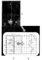
도 1은 한 눈의 사진을 도시한다. 도 1(a)는 전형적으로 변위의 변화를 찾기 위해 모니터링된 눈의 영역을 예시한다. 도 1(b)는 건강한 안구 운동의 톱니 프로파일 특성을 나타내는, 시간에 대한 눈 변위의 그래프를 도시한다. 도 1(c)는 눈 변위 신호로부터 도출된 눈 속도의 그래프를 도시한다.
도 2는 연속적인 이미지 프레임들이 픽셀 속도의 추정치로 변환되는 예를 도시한다. 도 2(a)는 카메라로부터 수신된 눈의 예시적 이미지이다. 도 2(b)는 옵티컬 플로우 알고리즘에 의해 제공된 픽셀 속도 벡터들의 예를 도시한다. 도 2(c)는 옵티컬 플로우 속도 벡터들의 영역 속도 평균의 그래프의 예이다.
도 3은 본 발명의 바람직한 프로세스 단계들의 개요를 도시한다.
도 4는 모의 가장자리 에지와 검출기 응답의 그래프들을 도시한다. 도 4(a)는 관찰된 것과 사이즈(σ= 5)가 유사한 예시적인 입력 에지를 도시한다. 도 4(b)는 실제로 직면하게 되는 것을 나타내는 단속적 속도 값들을 이용하여, 계산된 응답 곡선들(3가지 예시적인 속도(v = 1; 3; 5 픽셀들/프레임 각각)에 대한)을 도시한다.
도 5는 눈을 보기 위한 명확한 시선을 제시하기 위해 디스플레이에 근접하게 위치한 카메라를 포함하는 컴포넌트들의 한 예의 배열을 도시한다.
도 5(도면 좌측)는 로우 코히어런스 자극의 예를 도시한다. 도 5(도면 우측)는 풀 코히어런스 자극의 예를 도시한다.
도 6은 검출 프로세스의 양상들을 설명하는 교정 시도들로부터 획득된 비디오 프레임들의 시퀀스를 도시한다.
도 7 (a)-(e)는 픽셀 속도 정보와 OKN 일관성 값들 ![]()
도 8은 OKN 일관성 값들 ![]()
도 9는 속도 정보에서 피크들의 그래프를 도시한다.
도 10은 한편의 비디오 영상에서 단일 프레임, 프레임 0055에 적용된 도 3의 프로세스를 도시한다.
도 11은 카메라, 스크린 및 계산 디바이스를 포함하는 시스템의 컴포넌트들의 개요를 도시한다.
도 12는 본 발명의 다른 실시예에 따르는 미가공 머리 궤적과 안정화된 머리 궤적을 도시한다.
도 13은 머리 3D 포즈 추정과 안정화 절차를 도시한다.
도 14는 3D 공간에서 비디오 영상의 길이에 대한 머리 궤적 추정을 도시한다.The invention will now be described, by way of example only, with reference to the drawings.
Figure 1 shows a picture of an eye. Figure 1 (a) illustrates the area of the eye that is typically monitored to find a change in displacement. Fig. 1 (b) shows a graph of eye displacement over time, showing the tooth profile characteristics of healthy eye movements. 1 (c) shows a graph of the eye velocity derived from the eye displacement signal.
Figure 2 shows an example in which successive image frames are converted into estimates of the pixel speed. Figure 2 (a) is an exemplary image of the eye received from the camera. Fig. 2 (b) shows an example of the pixel velocity vectors provided by the optical flow algorithm. Fig. 2 (c) is an example of a graph of area velocity averages of optical flow velocity vectors.
Figure 3 shows an overview of the preferred process steps of the present invention.
Figure 4 shows graphs of simulated edge and detector responses. Figure 4 (a) shows an exemplary input edge that is similar in size (sigma = 5) to that observed. Figure 4 (b) shows the calculated response curves (for three exemplary velocities (v = 1; 3; 5 pixels / frame each) using intermittent velocity values to indicate that they are actually encountered .
Figure 5 shows an example arrangement of components including a camera positioned proximate the display to provide a clear view of the eye.
Fig. 5 (left side of Fig. 5) shows an example of low coherence stimulation. Fig. 5 (right side of Fig. 5) shows an example of full coherence stimulation.
Figure 6 shows a sequence of video frames obtained from calibration attempts illustrating aspects of the detection process.
Figs. 7 (a) - (e) show pixel speed information and OKN consistency values ![]()
Figure 8 shows the OKN consistency values ![]()
9 shows a graph of peaks in velocity information.
Figure 10 shows the process of Figure 3 applied to a single frame,
Figure 11 shows an overview of components of a system including a camera, a screen, and a computing device.
Figure 12 shows a raw head trajectory and a stabilized head trajectory according to another embodiment of the present invention.
Figure 13 shows a head 3D pose estimation and stabilization procedure.
Figure 14 shows a head trajectory estimate for the length of a video image in 3D space.
눈 추적Eye tracking
종래 기술의 비디오-안 전위도 검사(video-oculography) 기술은 주로 이미지에서 콘트라스트 전이들에 작용하는 에지 검출 알고리즘에 의한 처리를 위해 이미지에서의 위치를 요구한다. 따라서, 위치는 동공, 가장자리 에지 또는 눈꺼풀들과 같은 눈의 하이 콘트라스트 특징이어야만 한다. 이들 특징의 움직임은 변위 신호를 결정하기 위해 프레임별로 추적될 수 있다. 표준 RGB 카메라에 의해 녹화된 영상은 특히 어두운 홍채들에 대해, 일반적으로 눈의 특징들 사이에서 열악한 콘트라스트를 생성할 것이다. 도 1(a)는 비디오 녹화시 프레임 내의 열악한 콘트라스트를 예시한다. 도 1(a)는 또한 이미지가 어떻게 각막 반응들, 속눈썹들 및 눈꺼풀들에 의해 더 오염될 수 있는지를 보여준다. 비디오 녹화시 이들 특징의 콘트라스트를 향상하고, 이에 따라 에지 검출 알고리즘의 성능을 향상하기 위해, 적외선 광이 눈을 조명하는데 사용된다. 헤드 마운트들 또는 턱받침들은 녹화 장비와 관련하여 눈들을 안정화시키는데 사용될 수 있다. 그러나 젊은 피험자들은 머리 장착형 장비 및 이들의 머리를 고정된 곳에 두는 것에 부정적이다.Prior art video-oculography techniques require a position in an image for processing by an edge detection algorithm, which primarily affects contrast transitions in the image. Thus, the position must be a high contrast feature of the eye, such as a pupil, edge edge or eyelids. The motion of these features can be tracked frame by frame to determine the displacement signal. Images recorded by standard RGB cameras will produce poor contrast, especially among dark features, especially for dark irises. Figure 1 (a) illustrates poor contrast within a frame during video recording. Figure 1 (a) also shows how images can be more contaminated by corneal reactions, eyelashes, and eyelids. Infrared light is used to illuminate the eye in order to improve the contrast of these features in video recording and thus the performance of the edge detection algorithm. Head mounts or chin rests may be used to stabilize the eyes in relation to the recording equipment. However, young subjects are negative about putting head-mounted equipment and their heads in a fixed position.
하나의 특정 실시예는 비디오 영상으로부터 OKN의 검출을 허용하는 비디오-안 전위도 검사 시스템 및 방법이다. 비디오 영상은 피험자가 시각적 자극을 볼 때 눈의 변위보다 오히려, 속도의 추정치를 만드는데 이용된다. 특히, 본 발명은 옵티컬 플로우로 알려진 이미지 처리 알고리즘의 적용에 의해 눈의 가장자리 영역의 조잡한 결정 내에서 픽셀들의 속도 추정치를 결정하는 것을 포함한다. 바람직한 실시예들에서, Lucas-Kanade 옵티컬 플로우 알고리즘이 이용된다. 이 접근법의 주요 장점은 이미지 왜곡을 일으키는 열악한 이미지 콘트라스트와 다른 문제들과 함께 동작할 때 시스템 및 방법의 강건성을 향상시키기 위해 정확한 에지 검출이 요구되지 않는다는 것이다. 시스템 및 방법은 또한 종종 종래 기술의 변위 기반 접근법들을 혼동시키는 눈꺼풀들 또는 속눈썹들과 같은 고정 장애들에 둔감하다. 또한, 눈의 특정 양상들 또는 특징들의 검출, 예를 들어 눈 내에 존재하는 눈곱, 라인 또는 클리어 에지의 검출이 요구되지 않는다. 또한, 비틀림(tonsional) 움직임의 측정이 요구되지 않는다.One particular embodiment is a video-eye level inspection system and method that allows detection of OKN from a video image. The video image is used to create an estimate of the velocity rather than the displacement of the eye when the subject sees visual stimuli. In particular, the invention includes determining a velocity estimate of pixels within the coarse determination of the edge region of the eye by application of an image processing algorithm known as optical flow. In the preferred embodiments, the Lucas-Kanade optical flow algorithm is used. The main advantage of this approach is that accurate edge detection is not required to improve the robustness of the system and method when operating with poor image contrast and other problems that cause image distortion. The systems and methods are also often insensitive to fixed disorders such as eyelids or eyelashes that confuse the displacement-based approaches of the prior art. It is also not required to detect certain aspects or features of the eye, for example, to detect eye, line or clear edges present in the eye. Also, no measurement of the tonsional motion is required.
옵티컬 플로우 알고리즘에 의해 제공된 속도 추정치는 조잡하게 결정된 가장자리 영역에서 픽셀 속도들의 평균이다. 경험적 분석은 OKN의 존재와 방향을 결정하기 위해 결정된 속도 추정치에 적용될 수 있다. 도 1(c)에 도시된 바와 같은, 속도 추정치 정보는 또한 수동으로 건강한 눈 속도 정보와 비교될 수 있으며, 특히, 눈 및/또는 시각 경로의 건강함을 비교 판단하기 위해, OKN이 더 이상 존재하지 않은 속도 임계값과 비교될 수 있다. 속도 추정은 또한 사람의 주시 방향을 추적하는데 이용될 수 있다. 주시 방향은 시각적 자극이 이들의 주의를 얻는 것과 같은 정보를 포함하는 사람의 행동 특성을 판단하는데 이용될 수 있다.The velocity estimate provided by the optical flow algorithm is the average of the pixel velocities in the roughly determined edge region. Empirical analysis can be applied to the determined speed estimates to determine the presence and direction of OKN. The velocity estimate information, as shown in Figure 1 (c), can also be manually compared to healthy eye velocity information, and in particular, to compare the health of the eye and / or visual path, And can be compared with a non-speed threshold. Speed estimation can also be used to track the direction of the person's gaze. The gaze direction can be used to judge a person's behavioral characteristics that include information such as visual stimuli gaining their attention.
일 실시예에서, 시스템은 사전 녹화된 비디오 영상에 적용된다. 또 다른 실시예에서, 시스템은 카메라로부터의 비디오 신호에 실시간으로 적용된다. 다양한 실시예들은 OKN 응답을 도출하도록 설계된 시각적인 자극 제시 시스템에 결합된다. 카메라와 계산 능력 양자를 갖는 휴대용 또는 핸드헬드 디바이스, 예를 들어 스마트폰, 태블릿 또는 랩톱 디바이스가 이용 가능할 수 있다. 그러나 통상의 기술자는 적절한 자극의 표시와 비디오 영상의 녹화를 개별적으로 할 수 있는 디바이스가 이용될 수 있음을 인식할 것이다.In one embodiment, the system is applied to pre-recorded video images. In yet another embodiment, the system is applied in real time to the video signal from the camera. Various embodiments are combined into a visual stimulus presentation system designed to derive an OKN response. Portable or handheld devices, such as smart phones, tablets or laptop devices, with both a camera and a computing capability, may be available. However, the ordinary artisan will recognize that devices capable of individually displaying indications of appropriate stimuli and video images may be used.
옵티컬 플로우 알고리즘으로부터 획득된 속도 정보는 자극이 피험자의 눈에서 OKN을 도출했는지 검출하는데 이용된다. OKN이 더 이상 검출되지 않은 임계값에서의 자극 파라미터들은 시각적 성능의 표시를 제공한다. 임상은 안구 운동으로부터 결정된 속도 정보를 검토할 수 있다. 대안적으로, 통계적 분석 프로세스는 OKN의 존재 또는 부재를 결정하기 위해 속도 정보에 적용될 수 있다.The velocity information obtained from the optical flow algorithm is used to detect whether the stimulus has derived OKN from the eye of the subject. The stimulus parameters at the threshold at which OKN is no longer detected provide an indication of visual performance. The clinician can review the velocity information determined from eye movements. Alternatively, the statistical analysis process may be applied to the rate information to determine the presence or absence of OKN.
일부 실시예에 따르면, 통계적 프로세스는 눈의 영역으로부터 결정된 옵티컬 플로우 필드의 영역 평균 속도를 계산하고 있다. 일부 실시예에서, 눈의 가장자리 영역은 가장자리 영역이 에지 검출 프로세스로부터 조잡하게 결정되는 경우에 이용된다. 다른 실시예들에서는, 눈의 다른 영역들 또는 영역들의 조합이 이용되어 홍채와 같은, 콘트라스트 불연속을 적어도 제공한다. 콘트라스트 불연속은 속도 정보가 분석될 눈의 영역을 추적하는데 이용된다.According to some embodiments, the statistical process is calculating the area mean velocity of the optical flow field determined from the area of the eye. In some embodiments, the edge region of the eye is used when the edge region is determined coarsely from the edge detection process. In other embodiments, other regions of the eye or a combination of regions are used to provide at least a contrast discontinuity, such as iris. Contrast discontinuity is used to track the area of the eye for which velocity information is to be analyzed.
Lucas-Kanade 특징 추적은 또한 머리 움직임을 추적하는데 이용될 수 있다. 안구 운동은 수량화될 수 있고, 머리 움직임도 수량화될 수 있다. 머리 움직임의 결정은 머리 장작형 비디오 장비에 대한 요건을 부정할 수 있다.Lucas-Kanade feature tracking can also be used to track head movements. Eye movements can be quantified, and head movements can be quantified. Determination of head movement can negate the requirement for head-mounted video equipment.
OKN을 도출하는데 사용된 시각적 자극의 한 예는 도 5에 도시된 바와 같이 16" 음극선관(CRT) 상에서 250개의 움직이는 화이트 도트를 가진 시각 디스플레이이다. 통상의 기술자는 디스플레이가 표시될 자극 비디오의 스크린에 대해 적당한 사이즈와 해상도의 임의의 스크린일 수 있음을 인식할 것이다. 예를 들어, CRT 스크린, LCD 또는 핸드헬드 디스플레이가 이용될 수 있다. 일부 실시예에서, 도트들은 사이즈가 대략 0:5°이고 약 8초 동안 8:3° 원형 윈도우에 제시된다. 일부 실시예에서, 도트들은 약 8.3°/초에서 움직인다. 일부 실시예에서, 함께 움직이는 도트들 대 전체 도트들의 수의 비는 조정 가능하다. 풀 도트 코히어런스는 도 5의 우측에 도시된 바와 같이, 동일 방향으로 움직이는 도트들을 100% 갖는 반면, 로우 도트 코히어런스는 도 5의 좌측에 도시된 바와 같이, 함께 움직이는 모든 도트들 중 30-38%를 갖고, 나머지는 랜덤하게 움직인다. 일부 실시예에서, 도트들의 코히어런스도 조정가능하다.One example of a visual stimulus used to derive OKN is a visual display with 250 moving white dots on a 16 "cathode ray tube (CRT), as shown in Figure 5. A typical technician would have a screen of stimulated video For example, a CRT screen, an LCD, or a handheld display may be used. In some embodiments, the dots may be of a size approximately 0: 5 [deg.] In some embodiments, the dots move at about 8.3 ° / sec. In some embodiments, the ratio of the number of dots traveling together to the total number of dots is adjustable . As shown in the right side of Fig. 5, the full dot coherence has 100% of the dots moving in the same direction, while the low dot coherence is shown on the left side of Fig. 5 As shown, it has 30-38% of all dots moving together and the rest moves randomly. In some embodiments, the coherence of the dots is also adjustable.
한 예에서, CRT 디스플레이는 피험자의 눈들로부터 대략 60cm의 거리에 위치한다. 비디오 영상은 초당 25프레임에서 RGB 이미지들(1920 × 1080 픽셀들)의 비디오 영상을 전달하는 소니 디지털 고해상도 카메라(HDR-CX7EK, 소니(사), 도쿄, 일본)를 이용하여 수집된다. 카메라는 눈들을 보기 위한 명확한 시야를 제공하기 위해 디스플레이 근처에 위치한다. 이 배열(피험자 없는)은 일반적으로 도 5에 도시된다.In one example, the CRT display is located at a distance of about 60 cm from the subject's eyes. Video images are collected using a Sony digital high resolution camera (HDR-CX7EK, Sony, Tokyo, Japan) that delivers video images of RGB images (1920 x 1080 pixels) at 25 frames per second. The camera is positioned near the display to provide a clear view of the eyes. This arrangement (without subjects) is generally shown in Fig.
또 다른 예에서, 특히 젊은 테스트 피험자의 주의를 개선하기 위해, 시각적 자극 비디오는 만화와 같은, 아이들에게 흥미를 유발하는 비디오 세그먼트에 삽입된다. 만화 또는 다른 유형의 애니메이션 비디오는 시각적 자극 비디오가 OKN 데이터를 획득하는데 적당한 기간 동안 표시되기 전에 젊은 피험자의 주의를 얻는데 적당한 기간 동안 표시된다. 만화는 주의가 약해지거나 대안적으로 OKN 비디오가 종료될 때 표시될 수 있다. 만화는 제어 디바이스에 의해 자동적으로 또는 조작자에 의해 수동으로 디스플레이에 스위칭되고 이로부터 스위칭될 수 있다. 또 다른 예에서, 만화는 제1 스크린에 표시될 수 있고, OKN 자극 비디오는 제2 스크린에 표시될 수 있다. 제1 스크린은 피험자의 주의를 획득하기 위해 스위칭 온되고, 그 후 제2 스크린은 제1 스크린을 스위칭 온 및 오프하여 피험자가 OKN 자극을 보게 한다.In another example, in order to improve the attention of young test subjects in particular, visual stimulus videos are inserted into video segments that are of interest to children, such as cartoons. A cartoon or other type of animated video is displayed for a period of time suitable for getting attention of a young subject before the visual stimulus video is displayed for a period of time sufficient to obtain OKN data. Comics can be displayed when attention is weakened or alternatively when the OKN video ends. The cartoons can be switched to and switched from the display either automatically by the control device or manually by the operator. In another example, the comic can be displayed on the first screen, and the OKN stimulated video can be displayed on the second screen. The first screen is switched on to obtain the subject's attention and then the second screen switches on and off the first screen to allow the subject to see the OKN stimulus.
일부 실시예들에서, 비디오 영상은 비디오 데이터를 처리할 수 있는 계산 디바이스와 같은 시스템에 입력된다. 그러한 시스템의 일 예는 PC에서 실행하는 MATLAB 소프트웨어이다. 계산 디바이스는 수신하는 비디오 영상을 수신하고 그 영상의 조작과 분석을 수행하는 하드웨어와 소프트웨어를 구비한다. 대안적으로 계산 디바이스는 예컨대 마이크로프로세서 또는 마이크로컨트롤러와 같은 독립형 시스템일 수 있다. 도 11은 눈 영상을 녹화하는 카메라(60), 자극을 표시하는 스크린(70), 및 계산 디바이스(80)를 포함하는 시스템의 컴포넌트들의 개관을 나타낸다. 이러한 컴포넌트들 각각은 전술한 바와 같이 예컨대 스마트폰 또는 태블릿과 같은 인클로저(90) 내에 포함될 수 있다.In some embodiments, the video image is input to a system, such as a computing device, capable of processing the video data. One example of such a system is MATLAB software running on a PC. The computing device comprises hardware and software for receiving a video image to be received and for performing manipulation and analysis of the image. Alternatively, the computing device may be a stand-alone system such as, for example, a microprocessor or microcontroller. 11 shows an overview of components of a system including a
다양한 실시예들에 따라 OKN을 결정하는 방법이 다음의 단계들에 따라 수행된다. 눈의 영상을 포함하는 비디오 시퀀스는, 눈이 자극을 지켜보는 동안 녹화된다. 일부 실시예들에서, 비디오는 컬러이고, 예를 들어 1920 x 1080 픽셀들의 고해상도이지만, 또한 흑백일 수 있고/있거나 더 낮은 해상도일 수 있다. 일부 실시예들에서, 비디오 영상은 계산 복잡도를 감소시키기 위해 그레이 스케일로 변환된다. 순차적 프레임들로부터 픽셀 속도 정보를 결정하기 위해 옵티컬 플로우 이미지 처리 알고리즘이 비디오 영상에 적용된다. 속도 정보가 눈의 제한된 영역으로부터 결정되고, 그 영역은 눈의 가장자리 및/또는 가장자리 에지 부분이다. 영역은 에지 검출 알고리즘에 의해 결정된 눈의 가장자리 영역의 대강의 추정이다. 이미지 처리 알고리즘은 비디오 영상의 두 개의 연속적인 프레임에 걸쳐 결정된 눈의 가장자리 영역에서 픽셀 속도 정보에 의해 표현되는 옵티컬 플로우 정보를 출력한다. 속력 및 방향을 포함하는, 픽셀 속도 정보는 OKN의 존재와 방향을 결정하기 위해 직접적으로 평가될 수 있다.A method of determining OKN according to various embodiments is performed according to the following steps. A video sequence containing an image of the eye is recorded while the eye is watching the stimulus. In some embodiments, the video is color, for example a high resolution of 1920 x 1080 pixels, but can also be black and white and / or have a lower resolution. In some embodiments, the video image is converted to gray scale to reduce computational complexity. An optical flow image processing algorithm is applied to the video image to determine pixel rate information from sequential frames. Speed information is determined from a limited area of the eye, which is the edge and / or edge of the eye. The region is a rough estimate of the edge area of the eye as determined by the edge detection algorithm. The image processing algorithm outputs optical flow information represented by pixel velocity information in the edge region of the eye determined over two consecutive frames of the video image. Pixel rate information, including speed and direction, can be directly evaluated to determine the presence and direction of OKN.
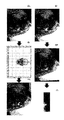
프로세스의 단계들의 일 예가 도 3에 도시되며, 두 개의 연속적인 이미지 프레임의 픽셀 속도의 추정치로의 변환이 이 도면에 도시된다. 제1 단계 10에서, 연속적인 비디오 프레임들 I(t)와 I(t + 1)이 고해상도 컬러 비디오 영상으로부터 발췌되고 그레이 스케일로 변환된다. 제2 단계 20에서, 눈의 가장자리 영역의 대강의 결정은 에지 맵을 결정하기 위해 비디오 영상에 적용되는 에지 검출 프로세스에 의해 결정된다. 에지 맵은 눈의 가장자리 부분 및 그러므로 옵티컬 플로우 정보가 결정될 비디오 영상의 영역의 위치의 결정을 나타낸다. 에지 맵은 유용할 옵티컬 플로우 정보를 위해 정확하게 결정될 필요는 없다. 프로세스는 비디오 영상 내의 프레임들 전체에 걸쳐 획득된 가장자리 에지 맵들 내의 변동에 대해 강건하다. 에지 검출은 히스테리시스 임계치화를 가진 Prewitt 연산자의 적용에 의해 이상적으로 수행된다. 그러나, 통상의 기술자는 다른 에지 검출 전략들을 또는 연산자들이 가장자리 영역을 결정하는 데 사용될 수 있다는 것을 이해할 것이다. 특정 가중치 아래의 연결된 영역들 및 이미지 경계에 연결된 영역들은 제거된다. 제2 단계 20과 동시에 또는 그전에 처리될 수 있는 제3 단계 30에서, 옵티컬 플로우 추정 프로세스는 픽셀 강도의 공간적 및 시간적 변화들로부터 픽셀 속도 정보를 결정한다. 도 1의 (c)에 도시된 바와 같이, 가장자리 영역은 눈의 재빠른 재설정 이벤트 동안(단속적 운동) 속도 스파이크를 나타내야 하고, 자극이 관찰되고 있는 다른 기간들 동안 스무스한 또는 일정한 속도 변화들을 나타내어야 한다.An example of the steps of the process is shown in FIG. 3, and the conversion of the pixel rate of two consecutive image frames into an estimate is shown in this figure. In a
도 2는 옵티컬 플로우 프로세스를 더 상세하게 도시한다. 도 2a는 눈을 나타내는 하나의 비디오 영상의 단일 프레임 또는 이미지를 도시한다. 도 2b는 연속적인 프레임들 사이에 픽셀 이동의 크기와 방향을 지시하는 다수의 벡터를 도시한다. 도 2c는 다수의 연속적인 프레임들에 대한 도 2b의 픽셀 벡터들의 평균 속도의 그래프이다.Figure 2 shows the optical flow process in more detail. 2A shows a single frame or image of one video image representing an eye. Figure 2B shows a number of vectors indicating the magnitude and direction of pixel movement between consecutive frames. Figure 2C is a graph of the average velocity of the pixel vectors of Figure 2B for a number of consecutive frames.
도 3의 제4 단계 40에서, 에지 검출 프로세스(20)에 의해 제공되는 가장자리 영역 정보는 마스킹된 속도 필드를 생성하기 위해 옵티컬 플로우 프로세스(30)에 의해 제공된 픽셀 속도 정보와 결합된다. 마스킹된 속도 필드는 검출된 가장자리 영역 내에서만의 속도 정보를 나타낸다. 제5 단계 50에서, 마스킹된 속도 필드로부터의 속도 정보는 비디오 영상 내의 연속적인 프레임들의 주어진 쌍에 대한 속도 값을 생성하기 위해 평균화된다. 도 3의 프로세스는 속도의 그래프가 시간의 함수로서 제공되도록, 비디오 영상 내의 원하는 만큼 많은 연속적인 프레임들에 대해 수행된다. 그 후 OKN 정보를 결정하기 위해 그래프가 분석될 수 있다.3, the edge region information provided by the
도 10은 하나의 비디오 영상에서 단일 프레임, 프레임 0055에 도 3의 프로세스가 적용되는 것을 도시한다. 도 10의 (a)는 프로세스에 입력되는 눈의 이미지를 도시한다. 도 8의 (b)는 에지 검출 프로세스에 의해 식별된 가장자리 영역을 도시한다. 도 10의 (c)는 픽셀 속도의 옵티컬 플로우 추정을 도시한다. 도 10의 (d)는 속도 정보로 오버레이된, 검출된 가장자리 영역을 도시한다. 도 10의 (e)는 검출된 가장자리 영역 내의 옵티컬 플로우 속도 정보의 결과적인 평균 속도 정보를 도시한다.Fig. 10 shows that the process of Fig. 3 is applied to a single frame,
옵티컬 플로우 추정 수학식이 수학식 1로서 아래에 제공된다.The optical flow estimation mathematical equation is given below as equation (1).
![]()
![]()
그리고 간단한 1D에서는 수학식 2의 형태로 된다.In a simple 1D, it takes the form of Equation (2).
![]()
![]()
수학식 3은 시간의 경과에 따라 상승 강도 에지 이동을 갖는 S자형 1D 에지(가장자리를 나타냄)를 나타낸다.Equation (3) represents an S-shaped 1D edge (indicating an edge) with a rising intensity edge shift with time.

V = v의 확인은 수학식 3의 도함수가 수학식 2 내로 치환됨으로써 제공된다. 픽셀 속도를 추정할 때 에러는, 수학식 1을 유도할 때 이용되는 작은 시간적 또는 공간적 변위들의 가정들, 디지털화, 노이즈로부터 비롯될 것이다. 그러나, 예상된 응답이 수학식 2로부터 관찰될 수 있다.The verification of V = v is provided by substituting the derivative of equation (3) into equation (2). The error in estimating the pixel velocity will result from the assumptions of small temporal or spatial displacements, digitization, noise used in deriving Equation (1). However, the expected response can be observed from equation (2).
도 4의 (a)는 t = -1, 0, 1(이 경우에, 에지가 v = 1 픽셀들/프레임의 속도를 갖는다)에 의해 인덱스된 세 개의 연속적인 프레임에서 실제로 관찰된 것과 크기(![]()
![]()
![]()
![]()
도 4의 (b)는 실제로 맞닥뜨리게 될 것을 지시하는 단속적 운동의 속도 값들을 이용하여 세 개의 예의 속도들(각각 v = 1; 3; 5 픽셀들/프레임)에 대해 ([-20; +20]의 픽셀 구간에 걸쳐) 계산된 응답 곡선들을 나타낸다. 응답 곡선들은 속도 추정치를 위치의 함수로서 나타낸다. 응답 곡선의 평균 ![]()
![]()
![]()
![]()
![]()
![]()
![]()
![]()
에지들에 대한 측정 가능한 응답들은 단속적 속도들에서 예상된다. 상기 분석은 또한 진짜 속도가 증가함에 따라, 진짜 속도로부터 편차가 증가할수록(포화를 향하여), 더 낮은 속도들에서 더 정확한 속도 추정들을 제안한다. 획득된 속도 정보는 단속적 움직임을 검출하기에 충분하고 그러므로 OKN의 존재 또는 부재의 결정을 내리기에 충분하다.Measurable responses to edges are expected at intermittent rates. The analysis also suggests more accurate velocity estimates at lower velocities as the real velocity increases, as the deviation from the real velocity increases (towards saturation). The acquired rate information is sufficient to detect intermittent motion and is therefore sufficient to make a determination of the presence or absence of OKN.
2차원 비디오에서 단속적 움직임들의 검출을 용이하게 하기 위해 1차원적 기술로의 수정이 가능하다. 일부 실시예들에서, 옵티컬 플로우 알고리즘은 Lucas-Kanade 방법이다. 그러나, 통상의 기술자는 다른 옵티컬 플로우 측정 방법들이 또한 적당한 경우에 이용될 수 있다는 것을 이해할 것이다. Lucas-Kanade 옵티컬 플로우 알고리즘의 가정은 V가 픽셀 p를 중심으로 한 작은 영역(픽셀들이 i = 1,.., n으로 인덱스됨)에 걸쳐 일정하다는 것이다. p에서의 속도의 최소 제곱 추정치는 수학식 4에 나타내어진다.In order to facilitate the detection of intermittent movements in two-dimensional video, it is possible to modify into a one-dimensional technique. In some embodiments, the optical flow algorithm is the Lucas-Kanade method. However, one of ordinary skill in the art will appreciate that other optical flow measurement methods may also be used where appropriate. The assumption of the Lucas-Kanade optical flow algorithm is that V is constant over a small area centered on pixel p (pixels are indexed by i = 1, ..., n). The least squares estimate of the velocity at p is shown in equation (4).
![]()
![]()
여기서,here,

그리고 W는 수학식 5에 나타낸 대각 n x n 행렬이다.And W is a diagonal n x n matrix shown in equation (5).
![]()
![]()
W는 바람직하게는 p 주위의 로컬 영역 내에 픽셀들의 가중 기여이다. Gaussian 윈도우가 이용될 수 있다. 가장자리 속도는 가장자리 영역에 걸쳐 모든 V(p)의 평균이고 수학식 6에 의해 나타내어진 바와 같고,W is preferably a weighted contribution of the pixels within the local region around p. Gaussian windows can be used. The edge velocity is the average of all V (p) over the edge area and is as represented by equation (6)

여기서 p는 눈을 포함하는 이미지 내의 픽셀들에 걸쳐 변동한다. 일부 실시예들에서, 다음의 가중화 팩터 q(p)가 수학식 7에 나타낸 바와 같이 이용되고,Where p varies over pixels in the image including the eye. In some embodiments, the following weighting factor q (p) is used as shown in equation (7)

여기서 ![]()
![]()
눈 속도 정보를 결정하기 위한 비디오-안 전위도 검사 기술이 설명되었다. 이 기술은 정상적인 어른 응시에서 보여지는 머리 움직임들에 의해 유도되는 에러, 눈 깜빡임, 반사 및 다른 에러 유도 팩터들에 대해 상당히 강건하다. 또한, 이 기술은 머리에 장착되는 장비를 참지 못할 청소년들 또는 피험자들에게 사용하기 위해 머리 안정화와 결합될 수 있다. 그러므로 이 기술은 달리 평가될 수 없었을 어린아이들 또는 청소년들에 용이하게 적용 가능한 비디오-안 전위도 검사 기술이다. 이 기술은 표준 '규격품의' 비디오 장비로 구현될 수 있음으로써, 비싼 지원 하드웨어에 대한 필요성을 회피한다. 위에서 설명된 기술에 기인하는 속도 정보 그래프는 훈련된 임상 전문가에 의해 직접적으로 분석될 수 있고/있거나 이제 기술될 OKN 검출 프로세스에 의해 더 처리될 수 있다.Video-eye level detection techniques for determining eye velocity information have been described. This technique is fairly robust against errors, eye blinking, reflections, and other error induction factors induced by head movements seen in normal adult gazing. In addition, this technique can be combined with hair stabilization for use with adolescents or subjects who will not tolerate head-mounted equipment. Therefore, this technique is a video-eye leveling technique that is easily applicable to young children or adolescents who could not otherwise be evaluated. This technology can be implemented with standard 'off-the-shelf' video equipment, thereby avoiding the need for expensive support hardware. The velocity information graph resulting from the techniques described above can be analyzed directly by a trained clinician and / or can be further processed by the OKN detection process as will now be described.
OKN 강도는 다음에 의해 결정될 수 있다. OKN을 나타내지 않는 피크들은, 예를 들어 임계치와 그들을 비교하고 임계치 아래의 그러한 피크들을 무시함으로써, 거절된다. 살아남은 피크들의 높이들의 평균이 결정되고 적절한 규격화 값 ![]()
![]()
다양한 실시예들에 따라 획득된 속도 정보로부터 OKN의 검출을 위한 프로세스 단계의 더 상세한 설명이 아래에 제공된다:A more detailed description of the process steps for the detection of OKN from the rate information obtained in accordance with various embodiments is provided below:
1. Vx(t) 신호의 소정의 구간 내의 모든 극대값들과 극소값들을 검출하고 그들 Q(j)을 레이블하며, 여기서 j = 1...M이다. 극대값들(또는 극소값들)은 프레임당 ![]()
![]()
2. 이러한 피크들과 임계치를 비교하고, 경험적으로 결정된 속도 임계치보다 작은 모든 피크들 ![]()
![]()
3. 축 위에(또는 아래에) 있는 극소값들(또는 극대값들)을, 그들이 눈의 방향에서 반전을 지시하지 않는다면, 거절한다. 유효한 속도 피크는 원칙적으로 제로 속도에 의해 정의된 축을 교차해야 한다: 느린-위상과 빠른-위상이 반대 방향들에서 발생한다(그리고 따라서 반대 부호를 가짐). 이 규칙은 또한 유효한 속도 피크의 얼굴에서 발생할 수 있는 "들쭉날쭉한 에지들" 또는 노이즈를 식별하는 것을 돕는다. 다시, M을 잔여 피크들의 개수로 재설정한다.3. Refuse the minimum values (or maxima) above (or below) the axis if they do not indicate inversion in the direction of the eye. Effective velocity peaks must in principle cross axes defined by zero velocity: slow-phase and fast-phase occur in opposite directions (and thus have opposite sign). This rule also helps to identify "jagged edges" or noise that can occur in the face of a valid speed peak. Again, reset M to the number of remaining peaks.
4. 프레임들의 소정의 개수 미만으로 떨어져 있는 ![]()
![]()
5. 일부 실시예들에서, 홀로 있는 극대값들 또는 극소값들 또는 극소값들이 거절된다(즉, 데이터 내에 동일 부호의 다른 피크들을 전혀 갖지 않는 것들). 고립된 피크는 종종 OKN의 결정을 지원하기에 충분한 증거가 아니다. 다시, M을 잔여 피크들의 개수로 재설정한다.5. In some embodiments, the maximums or minima or minima that are alone are rejected (i.e., those that have no other peaks of the same sign in the data). Isolated peaks are often not sufficient evidence to support OKN's decision. Again, reset M to the number of remaining peaks.
6. 규격화된 평균 피크 속도 ![]()
![]()
![]()
![]()
![]()
![]()
![]()
![]()

![]()
![]()
![]()
![]()
![]()
![]()
![]()
![]()
![]()
![]()
실험 작업에 대한 다음의 설명이 본 발명을 더 예시한다.The following description of the experimental work further illustrates the present invention.
실험 데이터 부분 1
검출 프로세스의 성능을 테스트하기 위해, 건강한 눈의 비디오 영상은 평균 25살의 6명의 참가자에 대해 녹화되었다. 획득된 영상은 수동으로 각각의 눈 주위의 비디오를 자름으로써 추가 처리를 위해 준비되었다. 비디오 녹화는 자극의 일시적 길이에 해당하는 일시적 길이로 절단되었다. 이 경우에, 자극은 8초였다. 전체 115의 인-포커스 시도들은 참가자로부터 획득되었는데, 여기서 70은 풀 코히어런스 자극을 위해 획득되었고 42는 로우 코히어런스 자극을 위해 획득되었다. 자극 코히어런스는 눈의 OKN 반응을 변경할 것으로 예상되었다.To test the performance of the detection process, video images of healthy eyes were recorded for six participants on an average of 25 years old. The acquired images were prepared for further processing by manually trimming the video around each eye. The video recording was truncated to a transient length corresponding to the transient length of the stimulus. In this case, the stimulation was 8 seconds. A total of 115 in-focus attempts were obtained from the participants, where 70 was obtained for full coherence stimulation and 42 was obtained for low coherence stimulation. The stimulus coherence was expected to change the OKN response of the eye.
속도 추정기와 OKN 검출기는 각각의 결과적인 비디오 레코드에 적용되었다. 결과적인 OKN 강도 측정의 부호는 OKN 방향의 표시자로서 이용되었다. 이용된 옵티컬 플로우 알고리즘은 Lucas-Kanade 옵티컬 플로우 솔버로 명명된 달러(2012년)에 의해 쓰여진 버전이었다.A velocity estimator and an OKN detector were applied to each resulting video record. The sign of the resulting OKN intensity measurement was used as an indicator in the OKN direction. The optical flow algorithm used was a version written by the dollar (2012) named Lucas-Kanade Optical Flow Solver.
제1의 17번의 시도는 100% 코히어런스를 가진 순수한 자극 패턴을 이용하여 녹화되었다. 이러한 시도들은 차후 사용을 위해 파라미터를 교정하는데 사용되었다. 시도 정확도는 모든 알고리즘 파라미터의 적절한 조정 뒤에 17번의 시도들(9는 정확한 왼쪽 검출들, 8은 정확한 오른쪽 검출들)의 발명자의 교정 세트에 대해서는 100%였다.The first 17 trials were recorded using a pure stimulus pattern with 100% coherence. These attempts were used to calibrate the parameters for future use. The try accuracy was 100% for the inventor's calibration set of 17 trials (9 for correct left detections and 8 for correct right detections) after a proper adjustment of all algorithm parameters.
도 6은 검출 프로세스의 측면들을 설명하는 교정 시도들로부터 획득된 일련의 비디오 프레임들을 보여준다. 추정된 가장자리 영역은 눈의 그레이스케일 이미지들 위에 덮어 씌워진다. 프레임 10은 쉬고 있는 눈을 보여주는 반면, 프레임들 54-56은 OKN 리셋 이벤트의 발생을 보여준다. 프레임 26은 눈 깜빡임 동안 가장자리 에지의 손실을 증명한다. 이러한 관측들은 한층 나아가서 도 7(a) 및 7(b)에 나타난 바와 같이 이러한 시퀀스를 위한 수평 및 수직 속도 트레이스들의 검사에서 더 확인된다. 도 6에서 스틸들의 하단 좌측 모서리에 나타난 프레임 부재들은 도 7(a) 및 7(b)의 수평축에 직접적으로 대응한다. OKN 데이터로서 받아들여진 피크들은 박스로 보여진다.Figure 6 shows a series of video frames obtained from calibration attempts illustrating aspects of the detection process. The estimated edge area is overlaid on the gray scale images of the eye.
프레임당 0.5 픽셀들의 경험적 설정 속도 임계치는 또한 점선으로 나타내어진다. 전체 115 시도들에 대한 검출기의 성능은 93%였는데, 여기서 52는 정확한 왼쪽 검출들, 53은 정확한 오른쪽 검출들, 및 10은 에러들이다. 풀 코히어런스 그룹을 위한 검출기의 성능은 96%였는데, 여기서 38은 정확한 왼쪽 검출들, 32는 정확한 오른쪽 검출들, 및 3은 에러들이다. 로우 코히어런스 그룹의 성능은 88%였는데, 여기서 14는 정확한 왼쪽 검출들, 21는 정확한 오른쪽 검출들, 및 7은 에러들이다.The empirically set speed threshold of 0.5 pixels per frame is also indicated by the dotted line. The performance of the detector for all 115 attempts was 93%, where 52 is the exact left detections, 53 is the correct right detections, and 10 are errors. The performance of the detector for the full coherence group was 96%, where 38 is the exact left detections, 32 is the correct right detections, and 3 are errors. The performance of the low coherence group was 88%, where 14 is the exact left detection, 21 the correct right detection, and 7 the errors.
OKN 일관성 값들 ![]()
![]()
![]()
![]()
3개의 부정확한 검출들이 도 7(c), (d) 및 (e)에 나타나지만, 마지막 패널 (f)는 최저 OKN 평가를 가진(즉, 부정확한 경우들의 평균에 근접한) 정확한 검출을 보여준다. 양방향 피크들은 서로 상쇄시키는 것으로 나타나는데, 이는 낮은 OKN 일관성 측정을 초래한다. 이 관측을 확인하기 위해, 이런 경우들에 대한 비디오들은 전문 관측자에 의해 검토되었고, 녹화들이 방향이 변한 OKN의 시퀀스를 실제로 포함한 것으로 간주되었다. 따라서, 피크들은 방법에 고유한 스퓨리어스 에러에 기인하지 않았다.7 (c), (d) and (e), the last panel f shows the correct detection with the lowest OKN estimate (i.e., close to the average of the inaccurate cases). Bidirectional peaks appear to cancel each other, which results in a low OKN consistency measurement. To confirm this observation, videos for these cases were reviewed by professional observers and the recordings were deemed to actually include a sequence of OKN changes direction. Thus, the peaks were not due to spurious errors inherent in the method.
실험 데이터 부분 2
이러한 실험의 목적은 OKN 검출 알고리즘이 OKN 안구 운동을 왼쪽 또는 오른쪽으로 가는 것으로 올바르게 분류할 수 있을지 평가하고 OKN 검출기의 성능을 경험이 풍부한 인간 관측자(TY)의 것과 비교하기 위한 것이었다. 이러한 실험을 위해 발명자는 OKN을 도출하기 위한 가변 움직임 코히어런스(variable motion coherence)를 가진 무선점 운동 그림(random dot kinematogram)(RDK)을 사용했다. 이러한 자극은 그러한 자극들 내에서의 글로벌 움직임의 인식이 비정상적 발달에 특히 취약할 수 있는 추가 줄무늬 시각령(extrastriate visual cortex)의 배측 영역(dorsal areas)에 의지하는 것으로 생각될 때 선택되었다. RDK는 심리학적 과제에 대한 행동 반응을 아직 제공할 수 없는 어린 아이들에서 움직임 코히어런스 임계치를 측정하기 위해 신뢰성 있는 느리고 빠른-단계의 시각성 안구 운동을 도출할 수 있다.The purpose of this experiment was to evaluate whether the OKN detection algorithm correctly classifies OKN eye movements as going left or right and compare the performance of the OKN detector with that of an experienced human observer (TY). For this experiment, the inventor used a random dot kinematogram (RDK) with variable motion coherence to derive OKN. These stimuli were chosen when the perception of global movement within such stimuli was thought to depend on the dorsal areas of the extrastriate visual cortex, which may be particularly vulnerable to abnormal development. The RDK can yield a reliable slow and fast-phase visual eye movement to measure motion coherence thresholds in young children who have yet to provide behavioral responses to psychological tasks.
RDK는 16" CRT 디스플레이의 100% 대조에서 제시되는 250개의 이동 화이트 도트들(0.5 deg 직경, 8 deg/초 속도)로 구성되었다. 도트는 8초 동안 8.3˚ 원형 윈도에 제시되었고 제한된 수명을 가지며 이에 의해 각각의 도트는 임의의 주어진 프레임 상에서 사그러지며 자극 내의 새로운 랜덤 위치에 다시 구성되는 25% 기회를 가졌다. 자극 애퍼츄어의 에지에 도달한 도트들이 주위에 감싸졌다. 자극의 코히어런스 레벨, 즉 도트들의 전체 수 대 동일한 방향으로 이동하는 도트들의 비는 자극에 존재하는 코히어런트 움직임의 세기를 변경하도록 조절될 수 있다. 발명자들은 풀 코히어런스(즉, 도트들의 100%가 같은 방향으로 이동)와 로우 코히어런스(모든 도트들 중 12 내지 15%는 일제히 이동되고, 반면에 나머지는 랜덤하게 이동)를 실험했다. 코히어런트 움직임의 방향은 시도들을 거쳐 임의 추출되었다. 로우 코히어런스 레벨은, 발명자에게 열화된 움직임 신호들에 의해 도출된 안구 운동에 대한 알고리즘을 계속 테스크할 수 있게 하는 동안 관측자를 위한 초과 임계치가 되도록 선택되었다(즉, 글로벌 움직임 방향이 여전히 분명히 가시적이었음). 1600 CRT 디스플레이는 50cm 떨어진 거리에 둔다. 비디오 영상은, 초당 25프레임에서 RGB 이미지들(1920x1080 픽셀들)로 구성되는 비디오를 전달하는 소니 디지털 고화질 카메라(HDR-CX7EK, 소니(사), 도쿄, 일본)를 사용하여 수집되었다. 카메라는 CRT의 옆에 배치되었고, 그리고 가장 가까운 눈에 집중되었다.The RDK consisted of 250 moving white dots (0.5 deg diameter, 8 deg / sec speed) presented in a 100% contrast of a 16 "CRT display. The dots were presented in an 8.3 degree circular window for 8 seconds and have a limited lifetime Thereby, each dot has a 25% chance of being reconstructed at a new random position in the stimulus, which is faded on any given frame. Dots reaching the edge of the stimulation aperture are wrapped around the coherence level of the stimulus, That is, the ratio of dots traveling in the same direction to the total number of dots can be adjusted to change the intensity of the coherent motion present in the stimulus. The inventors have found that full coherence (i.e., 100% Movement) and low coherence (12 to 15% of all dots moved in one go, while the rest move randomly). The perfume was randomly extracted through trials. The low coherence level was chosen to be an over-threshold for the observer while allowing the inventor to continue the algorithm for eye movements derived by the deteriorated motion signals The 1600 CRT display is 50 cm away from the video image, which is a Sony digital high-definition camera that delivers video consisting of RGB images (1920 x 1080 pixels) at 25 frames per second HDR-CX7EK, Sony, Tokyo, Japan). The camera was placed next to the CRT and focused on the nearest eye.
평균 연령 25살의 정상 시각을 가진 6명의 참가자는 턱받침에 의해 머리가 고정된 채로 양안으로 RDK 자극을 봤다. 고정 포인트는 각각의 RDK 프리젠테이션 시도 전후에 CRT 스크린의 중심에 제시되었다. 참가자들은 시도들 간에 포인트 인에 집중하고 시도 동안에 스크린의 중심을 응시하도록 지시받았다. 고정 포인트는 시도 동안에는 제시되지 않았다. 시도들로부터 획득된 영상은 모든 시도 내에서 각각의 눈 주위에 비디오를 수동으로 자름으로써 추가 처리를 위해 준비되었다. 각각의 시도에 대한 비디오는 참가자가 움직임 자극을 보고 있을 때 녹화된 프레임들만을 포함하기 위해 일시적으로 잘린다. 전체 115번 시도(8초 길이)는 참가자들(풀 코히어런스에 있는 73과 로우 코히어런스에 있는 42)로부터 획득되었다. 참가자들은 테스팅 동안 제공된 행동 반응에 의해 보여진 것처럼 각각의 시도에서 신호 도트들의 방향을 인지할 수 있다.Six participants with normal visual acuity at the age of 25 years showed RDK stimulation in both eyes with the head fixed by the chin rest. Fixed points were presented at the center of the CRT screen before and after each RDK presentation attempt. Participants were instructed to focus on the point in between attempts and to look at the center of the screen during the attempt. Fixed points were not presented during the trial. The images obtained from the trials were prepared for further processing by manually trimming the video around each eye in all attempts. The video for each attempt is temporarily truncated to include only the recorded frames when the participant is watching the motion stimulus. A total of 115 trials (8 seconds long) were obtained from participants (73 in Full Coherence and 42 in Low Coherence). Participants can recognize the direction of the signal dots in each attempt, as shown by the behavioral response provided during testing.
속도 추정기와 OKN 검출기는 각각의 결과적인 비디오 레코드에 오프라인으로 적용되었다. 검출기는 ![]()
![]()
![]()
![]()
![]()
![]()
![]()
![]()
모든 115번 시도에 대한 검출기의 성능은 인간 관측자에 대해서는 98%(53은 정확한 왼쪽 검출들, 60은 정확한 오른쪽 검출들, 2는 에러들)인데 반해 93%(54는 정확한 왼쪽 검출들, 53은 정확한 오른쪽 검출들, 8은 에러들)이었다. 풀 코히어런스 시도들에 대한 검출기의 성능은 인간 관측자에 대해서는 100%(38은 정확한 왼쪽 검출들, 35는 정확한 오른쪽 14 검출들)인데 반해 96%(38은 정확한 왼쪽 검출들, 32는 정확한 오른쪽 검출들, 3은 에러들)이었다.The performance of the detector for all 115 trials is 98% for human observers (53 is the correct left detection, 60 is the right detection, 2 is the error), while 93% Correct right detections, and 8 errors). The performance of the detector for full coherence attempts is 96% (38 is the exact left detections, 32 is the exact right), while the performance of the detector for human observers is 100% (38 is exact left detections and 35 is exact right 14 detections) Detections, and 3 are errors).
로우 코히어런스 시도들에서, 검출기는 인간 관측자에 대해서는 95%(15는 정확한 왼쪽 검출들, 25는 정확한 오른쪽 검출들, 2는 에러들) 정확한데 반해 88%(16은 정확한 왼쪽 검출들, 21은 정확한 오른쪽 검출들, 5는 에러들) 정확하게 수행되고, 또한 사소한 차이(Chi-Square = 1.40, p = 0.24)로 수행된다. 풀 코히어런스 시도들에서, 3/3(100%) 부정확하게 분류된 시도들은 정확하게 분류된 시도들(Chi-Square = 7.7, p< 0:005)에 대한 18/70(26%)과 비교하여 1작은 K 값을 가진다. 유사하게, 로우 코히어런스 시도들에서, 5/5(100%) 부정확하게 분류된 시도들은 정확하게 식별된 시도들(Chi-Square = 5.0, p = 0.02)에 대한 17/37(46%)과 비교하여 1작은 K 값을 가진다. 부정확하게 분류된 시도들에 대한 속도 트레이스들의 검사는 낮은 값들이 상대적으로 동등하게 0의 주위에 배포되는 속도 피크들로 인한 것임을 나타낸다. 이러한 양방향 피크들은 서로를 상쇄시키는 것처럼 보여 낮은 OKN 일관성 측정을 초래한다.In the low coherence attempts, the detector is 88% correct (16 is the correct left detection, 21 is correct), whereas the detector is 95% accurate for human observers (15 for accurate left detections, 25 for accurate right detections and 2 for errors) Is correct right detection, 5 is error) and is performed with a minor difference (Chi-Square = 1.40, p = 0.24). In full coherence trials, 3/3 (100%) incorrectly classified trials were compared to 18/70 (26%) for correctly classified trials (Chi-Square = 7.7, p <0: 005) And has a small K value. Likewise, in the low coherence attempts, 5/5 (100%) incorrectly classified trials were 17/37 (46%) for correctly identified trials (Chi-Square = 5.0, p = 0.02) And has a small K value. An examination of the rate traces for incorrectly classified attempts indicates that the lower values are due to the velocity peaks distributed relatively equally around zero. These bidirectional peaks appear to cancel each other, resulting in low OKN consistency measurements.
이러한 관측을 확인하기 위해, 검출기에 의해 부정확하게 분류된 8번 시도의 비디오 영상은 경험이 풍부한 인간 관측자(TY)에 의해 제2 시간 동안 검토되었다. 그것은 양방향 속도 스파이크들이 비디오 영상 내의 가시적인 실제 안구 운동으로부터 얻어지고 방법의 스퓨리어스 에러에 의해 야기되지 않았다는 것으로 확인되었다. 그것은 또한 녹화들이 방향이 변한 OKN의 시퀀스들을 실제로 포함한다는 것을 알아 냈다.To confirm these observations, video images of eight trials that were incorrectly classified by the detector were reviewed for a second time by an experienced human observer (TY). It has been found that bidirectional velocity spikes are derived from visible real eye movements in video images and are not caused by spurious errors in the method. It also found that the recordings actually contain sequences of directional OKN sequences.
실험 데이터 부분 3
이러한 실험은 3가지 목적을 갖는다: OKN 일관성 측정이 자극 속도에 의해 영향을 받았는지 평가하는 것, OKN 검출기가 참가자들이 고정 자극을 수동적으로 보는 동안의 시도들을 정확하게 거부하는지 평가하는 것, 그리고 검출 기술이 표준 웹캠을 이용하여 획득된 영상에 적용될 수 있을지 평가하는 것. 고 콘트라스트 구형 격자 자극은 이러한 유형의 자극이 임상 연구에서 OKN을 유발하기 위해 일상적으로 이용되기 때문에 실험에 사용되었다.These experiments have three purposes: to assess whether the OKN consistency measurement is affected by the rate of stimulation, to evaluate whether the OKN detector accurately rejects attempts while the participants passively watch the stationary stimulus, Evaluate whether it can be applied to images acquired using this standard webcam. High contrast spherical lattice stimulation was used in the experiment because this type of stimulus is routinely used to induce OKN in clinical studies.
IBM P275 음극선 스크린(2000 스크린, 1600x1200의 해상도와 60Hz 리플레시 레이트) 스크린은 3.8 사이클/deg(0.9 LogMAR에 해당)의 기본 공간 주파수를 가진 100% 콘트라스트 구형파 격자가 제시된 1.9 m에서 보인다. 3개의 프리젠테이션 속도(0 deg/s, 5 deg/s 및 10 deg/s)가 이용되었고, 격자는 항상 우측에서 좌측으로 움직였다. OKN 눈 반응의 비디오 영상은 참가자 눈으로부터 10cm에 배치된 HD 프로 920 로지텍 웹캠(30Hz 프레임 레이트로 설정)을 이용하여 획득되었다. 자극은 웹캠으로부터 공급된 비디오를 동시에 녹화하는 동안 제시되었다.The IBM P275 cathode ray screen (2000 screen, 1600x1200 resolution and 60Hz refresh rate) screen is shown at 1.9 m with a 100% contrast square wave grating with a default spatial frequency of 3.8 cycles / deg (corresponding to 0.9 LogMAR). Three presentation speeds (0 deg / s, 5 deg / s and 10 deg / s) were used and the grating always moved from right to left. A video image of the OKN eye response was obtained using a HD Pro 920 Logitech webcam (set at 30 Hz frame rate) placed 10 cm from the participant's eye. The stimulus was presented while simultaneously recording the video supplied from the webcam.
평균 연령 = 23이고 정상 시각을 가진 5명의 관측자의 그룹은 양안으로 자극 패턴들을 봤고, 자극 프리젠테이션 기간 동안 드리프팅 자극 패턴의 중심을 응시하도록 지시받았다. 관측자의 머리는 턱받침을 이용하여 고정되었다. 각각의 관측자는 각각의 자극 속도(0, 5 및 10 deg/s)의 한번의 시도를 완료했다. 안구 운동은 최소 8초 동안 녹화되었고 녹화는 위에서 기술된 옵틱 플로우 방법을 이용하여 처리되었다.A group of 5 observers with an average age of 23 and a normal vision saw stimulus patterns in both eyes and were instructed to look at the center of the drifting stimulus pattern during the stimulus presentation period. The head of the observer was fixed using a chin rest. Each observer completed a single attempt at each stimulation rate (0, 5, and 10 deg / s). Eye movement was recorded for a minimum of 8 seconds and recording was processed using the optic flow method described above.
가장자리 검출 파라미터는 카메라를 눈에 더 가까이 배치한 데서 초래된 눈의 더 큰 이미지를 고려하도록 수정되었다. 실험 1에서, 20 미만의 중량을 가진 픽셀의 그루핑들은 버려진다. 이러한 실험에서, 임계치는 녹화된 가장자리의 증가된 크기를 고려하기 위해 300개 픽셀로 증가되었다. 추가적인 경험 규칙이 이러한 실험에 도입되었다는 것에 또한 유의한다. 2개의 연속적 피크들이 검출되었지만(같은 방향에서), 연속적인 단속적 피크들(subsequent saccadic peaks) 사이의 시간 간격이 4초 임계치보다 더 컸다면, 피크들 사이의 간격은 OKN의 느린 위상으로 인해 일치하지 않는 것으로 가정되었다. 추가적인 인접한 피크들(동일한 부호의)이 없을 경우에, 이러한 2개의 피크는 버려질 것이다.The edge detection parameter was modified to take into account the larger image of the eye resulting from placing the camera closer to the eye. In
고정 자극에서, 속도 트레이스들은 ![]()
![]()
![]()
![]()
![]()
![]()
![]()
![]()
![]()
![]()
![]()
![]()
OKN 검출기는 구형파 격자 자극을 보는 참가자의 웹-캠 영상이 제공될 때 OKN의 존재 또는 부재에 민감했다. 유효한 OKN이 검출된 경우에, OKN 검출기에 의해 생성된 |![]()
![]()
따라서, 실험은 여기에서 설명된 실시 형태들이 RDK들과 구형파 격자들에 의해 도출된 OKN을 검출할 수 있다는 것을 나타내고, 경험이 풍부한 인간 관측자의 것과 비교할 만한 정확도를 갖는다. 따라서, 객관적으로 어린 아이들의 시각 기능의 평가는 OKN의 비자발적, 재귀 안구 운동을 이용하여 가능하다. 특히, 2세 또는 대략 2세의 어린 아이들은 본 발명이 제공할 수 있는 정보로부터 특별히 유익한 것으로 알려졌다.Thus, the experiment shows that the embodiments described herein are able to detect OKNs derived by RDKs and square wave gratings, and have an accuracy comparable to that of an experienced human observer. Therefore, objectively assessing the visual function of young children is possible using OKN's involuntary, recursive eye movements. In particular, young children of about two or about two years old have been found to be particularly informative from the information that the present invention can provide.
상기 설명된 실시 형태들은 광고와 보안의 분야들에서 사용된다. 예를 들면, 사람의 주시 방향은 소비자의 관심 또는 행동과 관련된 정보를 결정하기 위해 추적될 수 있다.The embodiments described above are used in the fields of advertising and security. For example, a person's direction of attention can be tracked to determine information related to a consumer's interest or behavior.
머리 추적Head tracking
앞서 논의된 바와 같이, 아이는 턱받침 또는 머리 장착 눈-추적 장비를 허용하지 않는다. 또한, 전술한 OKN 검출 프로세스를 갖는 비디오 영상 내의 머리 움직임은 의도하지 않게 안구 운동으로서 해석될 수 있고 안구 운동 측정의 정확도에 악영향을 줄 수 있다. 그러나 이러한 장비는 이전에는 정지한 채로 남을 수 없는 사람들로부터의 안구 운동의 안정한 비디오 영상을 검색하는 방법으로서만 생각되어 왔다.As discussed above, the child does not tolerate chin-rest or head-mounted eye-tracking equipment. In addition, the head movement in a video image with the OKN detection process described above can be unintentionally interpreted as eye movement and adversely affect the accuracy of the eye movement measurement. However, such a device has only been thought of as a method for retrieving stable video images of eye movements from people who could not remain stationary in the past.
본 발명의 다른 실시예들은 비디오 영상 내의 머리 움직임의 결정, 및 선택적으로는 그 결정된 머리 움직임을 보상하는 것에 관한 것이다. 머리 움직임의 정확한 결정은 턱받침 또는 머리 장착 장비가 무시되게 하고 전술한 OKN 검출 프로세스가 최적화되게 한다.Other embodiments of the invention relate to determining a head motion in a video image, and optionally compensating the determined head motion. The precise determination of head movement causes the chin rest or head mounting equipment to be ignored and the OKN detection process described above to be optimized.
일부 응용들에서, 머리 움직임 정보는 의도하지 않게 안구 운동으로 결정된 과도한 머리 움직임에 의해 생긴 오차들을 완화하기 위해 전술한 OKN 분석 시스템과 관련하여 수량화되어 사용된다. 다른 응용들에서, 머리 움직임 정보는 전술한 OKN 분석 시스템과 독립적으로 사용된다.In some applications, head motion information is quantitatively used in connection with the above-described OKN analysis system to mitigate errors caused by excessive head movement unintentionally determined as eye movement. In other applications, head motion information is used independently of the OKN analysis system described above.
특정 실시예에 따르면, 머리 움직임 정보는 다음을 포함하는 계산 시스템에 의해 이상적으로 착수되는 프로세스에 의해 비디오 영상으로부터 얻어진다:According to a particular embodiment, the head motion information is obtained from a video image by a process ideally undertaken by a calculation system comprising:
· 비디오 영상의 적어도 2개의 프레임 내의 동일한 안면 영역의 적어도 일부를 검출하는 것,Detecting at least a portion of the same face area in at least two frames of the video image,
· 적어도 2개의 프레임 사이의 동일한 안면 영역의 적어도 일부의 움직임의 측정을 결정하는 것, 및 Determining a measurement of movement of at least a portion of the same facial region between at least two frames, and
· 움직임의 결정된 측정에 대응하는 변환 정보를 결정하는 것.Determining the transformation information corresponding to the determined measurement of the motion.
로보스트 안면 특징들은 카메라에 의해 쉽게 식별되는 뚜렷한 색상 또는 음영 콘트라스트의 영역들을 포함한다. 조명 조정들이 선택적으로 피험자에 가해지고/가해지거나 비디오 영상은 안면 특징들의 구별을 개선하도록 처리된다. 일부 실시예들에서 안면 영역 내의 하나 이상의 로버스트 안면 특징들은 그들의 움직임이 추적될 수 있도록 결정된다.Robust facial features include areas of distinct color or shade contrast that are easily identified by the camera. Illumination adjustments are selectively applied to the subject and / or the video image is processed to improve the distinction of facial features. In some embodiments, one or more robust facial features within the facial region are determined such that their motion can be tracked.
안면 특징들은 비디오 영상의 적어도 2개의 프레임에서 식별되고 적어도 2개의 프레임 사이의 그들 안면 특징들과 관련한 움직임 정보를 결정함으로써 추적된다. 움직임 정보는 프레임 내의 화소들의 수와 같은 메트릭에 의해 수량화된다. 움직임 정보는 플래너 움직임에 관련하고 선택적으로 회전 또는 스케일 움직임에 더 관련될 수 있다.The facial features are tracked by identifying at least two frames of the video image and determining motion information associated with their facial features between the at least two frames. The motion information is quantified by the same metric as the number of pixels in the frame. The motion information may be related to the planar motion and optionally further relates to a rotation or scale motion.
변환 정보는 비디오 프레임 내의 머리의 움직임에 관련된다. 변환 정보는 머리의 움직임을 보상하기 위해 프레임을 이동시키거나 자름으로써 프레임 내의 머리 움직임을 안정화하는 데 사용된다.The transformation information relates to the motion of the head within the video frame. The transformation information is used to stabilize head movement within the frame by moving or trimming the frame to compensate for head movement.
일부 실시예들에서, 움직임 정보는 안면 특징들, 및 따라서 비디오 영상 내의, 머리의 회전, 스케일 및 병진 움직임 중 하나 이상과 관련한 데이터를 포함하는 변환 맵을 생성하는 데 사용된다. 제1 또는 이전의 프레임에 대해, 비디오 영상의 각 프레임에 대해 결정된 유사성 변환은 그 프레임 내의 머리 이미지를 위한 회전, 스케일 및 병진 움직임을 제공한다.In some embodiments, the motion information is used to generate a transformation map that includes data relating to at least one of facial features, and thus, rotation, scale, and translation of the head within the video image. For the first or previous frame, the similarity transformation determined for each frame of the video image provides rotation, scale, and translation movement for the head image within that frame.
일부 실시예들에서, 비디오 영상은 계산 명령어들을 처리할 수 있는 컴퓨터 또는 제어 디바이스(제어기)에 의해 처리된다. 제어기는 새로운 프레임 위치를 발생하도록 비디오 영상 내의 각각의 프레임을 상쇄하기 위해 맵의 역변환을 계산하고 적용한다. 그 결과는 프레임 내의 영상의 머리 부분이 비교적 정지되게 남고 그러므로 프레임이 변환된 양만큼 움직이는 동안 한 위치에 안정화된다. 일부 실시예들에서, 제어기는 안면 영역 또는 눈 영역과 같은, 관심 영역에 관한 각각의 프레임을 활동적으로 자르고 중심잡기 위해 맵의 역변환을 계산하고 적용하여, 각 프레임 내의 중심 잡히고 안정화된 새로운 비디오 영상을 생성한다.In some embodiments, the video image is processed by a computer or a control device (controller) capable of processing the calculation instructions. The controller computes and applies the inverse of the map to cancel each frame in the video image to generate a new frame position. The result is that the head of the image in the frame remains relatively stationary and therefore stabilizes in one position while the frame moves by the amount of the transformation. In some embodiments, the controller computes and applies the inverse transform of the map to actively crop and center each frame with respect to the region of interest, such as the facial region or the eye region, to generate a new, centered and stabilized video image within each frame .
안정화된 머리 위치는 머리 움직임이 처리된 영상으로부터 얻어진 안구 운동 데이터에 더 이상 영향을 주지 않음에 따라 예를 들어, 위에 언급된 OKN 검출 프로세스의 성능을 개선하는데 유용하다. 일부 실시예들에서 눈을 포함하는 프레임의 부분은 눈의 안정화된 영상이 전술한 자동화된 OKN 검출 방법으로 사용하는 것과 같은 더 이상의 OKN 분석을 위해 얻어진다. 이 프로세스에 의해 수집된 정보는 사람이 턱받침에 의해 제 위치에 그들의 머리가 고정될 때 또는 머리 장착 장비가 사용된 경우에 수집된 정보와 유사하거나 동일하다. 그러나 이 프로세스는 이러함 장비의 부담을 요구하지 않는다.The stabilized head position is useful for improving the performance of, for example, the OKN detection process described above as head movement no longer affects eye movement data obtained from the processed image. In some embodiments, the portion of the frame containing the eye is obtained for further OKN analysis, such that a stabilized image of the eye is used with the automated OKN detection method described above. The information collected by this process is similar or identical to the information collected when a person fixes their head in place by the chin rest or when a head-mounted instrument is used. However, this process does not require the burden of such equipment.
일부 실시예들에서 비반사 유사성 변환 맵은 2D 비디오 프레임으로부터 3D 물체의 병진 및 회전 정보를 추정하는 POSIT 알고리즘을 사용하여 생성된다. 적어도 4개의 3D 모델 점들(세계-공간 좌표들) 및 대응하는 2D 이미지 점들, 카메라의 초점 거리 및 주점(principal point)이 정확한 추정을 위해 필요하게 된다. 3D 모델 점 좌표들, 예를 들어, 마커 코너들은 고정되고 대응하는 2D 이미지 점들이 식별된다. 카메라 특성들은 아래에 나타낸 수학식 9-11을 사용하여 추정된다.In some embodiments, the non-reflective similarity transformation map is generated using a POSIT algorithm that estimates the translation and rotation information of the 3D object from the 2D video frame. At least four 3D model points (world-space coordinates) and corresponding 2D image points, camera focal length and principal point are needed for accurate estimation. 3D model point coordinates, e.g., marker corners, are fixed and corresponding 2D image points are identified. The camera characteristics are estimated using Equation (9-11) shown below.

![]()
![]()

이들 식에서 항들 fx 및 fy는 각각 (동일한 것으로 가정되는) x 및 y 방향에서의 초점 거리들이고 화소 단위들로 표현된다. 이미지 차원들이 (w, h)에 의해 주어지고, 카메라의 주점은 (cx, cy)에 의해 주어진다. 로드리게스의 회전 공식(Rodrigues' rotation formula)은 각각 X, Y, Z 방향들에 대한 회전들을 검색하기 위해 사용된다. POSIT 오차 평가는 수학식 12에 제시된 변환에 의해 3D 모델 점들을 2D 이미지 평면에 재투영함으로써 수행된다.In these equations, terms f x and f y are respectively the focal distances in the x and y directions (assumed to be the same) and are expressed in pixel units. The image dimensions are given by (w, h) and the camera's principal point is given by (c x , c y ). Rodrigues' rotation formula is used to search for rotations in the X, Y, Z directions, respectively. POSIT error estimation is performed by re-projecting the 3D model points onto the 2D image plane by the transformation shown in equation (12).

수학식 12에서, s는 화소 크기, x 및 y는 2D 이미지 점들, X, Y 및 Z는 3D 모델 좌표들, rij는 회전 파라미터들 및 Tx, Ty 및 Tz는 병진들이다.In
한 예시적인 실시예에서, 얼굴 영역은 PittPatt SDK 버전 5.2.2(구글(Google)에 의해 획득됨)뿐만 아니라, Computer Vision ToolBox MATLAB(MathWorks, Natick, VA)에 의해 제공된 Viola-Jones 알고리즘을 사용하여 비디오 영상의 비디오 프레임 내로부터 검출된다. 프레임 내의 로버스트 안면 특징들은 해리스(Harris) 코너 검출 알고리즘을 사용하여 식별된다. 로버스트 안면 특징들은 MATLAB에서 또한 이용 가능한 Kanade Lucas Tomasi(KLT) 점 추적기를 사용하여 연속하는 프레임들 사이에서 추적된다. 일부 실시예들에서 비반사 유사성 변환은 POSIT 알고리즘을 사용하여 후속하는 프레임들 사이의 추적된 점들의 변화로부터 발생된다. 역 유사성 변환은 다음에 후속하는 프레임들 사이의 안면 특징들의 위치의 변화들을 보상하기 위해 각 프레임에 상쇄로서 적용된다. 안면 특징들은 그럼으로써 초기 위치에 계산적으로 유지된다. 각 눈 주위의 영역은 안구 운동을 머리 움직임으로부터 분리하기 위해 각 프레임에서 잘릴 수 있다.In one exemplary embodiment, the face area is determined using the Viola-Jones algorithm provided by the Computer Vision ToolBox MATLAB (MathWorks, Natick, VA) as well as the PittPatt SDK version 5.2.2 (obtained by Google) Is detected from within the video frame of the video image. The robust facial features within the frame are identified using a Harris corner detection algorithm. Robust facial features are tracked between consecutive frames using the Kanade Lucas Tomasi (KLT) point tracker, which is also available in MATLAB. In some embodiments non-reflective similarity transformations result from changes in tracked points between subsequent frames using a POSIT algorithm. The inverse affinity transformation is applied as offset to each frame to compensate for changes in the position of facial features between subsequent frames. The facial features are thereby computationally maintained at the initial position. The area around each eye can be cut in each frame to separate eye movements from head movement.
도 13은 자동화된 예시적인 프로세스의 정확도를 비교하기 위한 수동 프로세스를 개괄한다. 도 13(d)는 녹화되어 있는 비디오 영상 전의 대상들의 얼굴 상에 수동으로 놓인 시각적 마커들을 도시한다. 시각적 마커들은 움직임이 녹화된 영상에서 측정될 수 있는 클리어 점을 제공한다. 녹화된 영상 내의 각각의 프레임에 대해, 각 마커의 5개의 코너 점들이 MATLAB 입력 명령을 사용하여 수동으로 선택되었다. 특징들이 선택되는 순서는 프레임에서 프레임까지의 특징들의 대응을 유지하기 위해 프레임들에 걸쳐 일관적이었다. 칼만 필터가 수동 점 선택은 잡음을 들어오게 하기 때문에 특징 추적을 원활히 하기 위해 사용되었다. 4개의 기준 점들이 각각의 녹화 내로 삽입되었고 각각의 비디오 프레임들에 걸쳐 추적되었다. 이들 점들은 중첩하면 수동과 자동 안정화의 차이들이 계산될 수 있다. 이들 점들의 좌표들은 수동으로 안정화된 프레임들과 자동으로 안정화된 프레임들 사이에 비교된다.Figure 13 outlines a manual process for comparing the accuracy of an automated exemplary process. Figure 13 (d) shows the visual markers placed manually on the faces of the objects before the video image being recorded. Visual markers provide clear points where motion can be measured in recorded images. For each frame in the recorded image, five corner points of each marker were manually selected using the MATLAB input command. The order in which features were selected was consistent across frames to maintain correspondence of features from frame to frame. The Kalman filter is used to facilitate feature tracking because the passive point selection allows noise to be heard. Four reference points were inserted into each recording and tracked over each video frame. When these points overlap, differences between manual and automatic stabilization can be calculated. The coordinates of these points are compared between manually stabilized frames and automatically stabilized frames.
도 13(a)는 자동으로 검출된 얼굴 영역 내에 배치된 해리스 코너들을 도시한다. 도 13(b)는 눈 영역이 각각의 프레임의 중심에 "고정된" 안정화된 비디오를 도시한다. 도 13(c)는 눈 주위의 영역들이 잘린 것을 도시한다. 도 13(d)는 수동으로 선택된 중신 점들을 갖는 마커들을 도시한다. 도 13(e)는 3D 자세 추정이 단위가 센티미터인 POSIT 알고리즘에 의해 결정된 것으로 도시한다. 도 13(f)는 추정된 머리 자세를 도시한 수동으로 선택된 마커 점들의 재투영을 도시한다. 도 14는 3D 공간 내의 비디오 영상의 길이에 대한 머리 궤적 추정을 도시한다.Figure 13 (a) shows the Harris corners located within the automatically detected face area. 13 (b) shows a stabilized video where the eye region is "fixed " to the center of each frame. Fig. 13 (c) shows that the regions around the eyes are cut off. Figure 13 (d) shows markers with manually selected center points. FIG. 13 (e) shows that the 3D posture estimation is determined by the POSIT algorithm, which is in units of centimeters. 13 (f) shows the re-projection of the manually selected marker points showing the estimated head posture. Figure 14 shows a head trajectory estimate for the length of a video image in 3D space.
도 12는 비디오 영상의 예시적인 길이 내의 결정된 안면 특징들의 궤적을 도시한 '+' 기호들을 갖는다. '*' 기호들은 맵의 역변환이 각각의 프레임에 적용된 후의 효과적으로 안정화된 결과를 도시한다.Figure 12 has " + " symbols showing the locus of determined facial features within an exemplary length of the video image. The symbols ' * ' indicate an effectively stabilized result after the inversion of the map is applied to each frame.
도 12에서, 얼굴들은 안정화 전에 (523.8037, 253.3558)±(18.6676, 8.9088) 픽셀들, 및 안정화 후에 (500.4114, 260.0309)±(1.8828, 1.4282)의 좌표들로 위치 설정된다. 결과적인 안정화된 영상은 결국 원래의 영상에 비해 머리 부분의 실질적인 안정화를 나타내는 안면 특징 위치들의 타이트한 그루핑을 나타낸다. 안정화된 영상은 다음에 원하는 영역으로 일관성있게 잘릴 수 있다.In Fig. 12, the faces are positioned with coordinates (523.8037, 253.3558) ± (18.6676, 8.9088) pixels before stabilization and (500.4114, 260.0309) ± (1.8828, 1.4282) after stabilization. The resulting stabilized image eventually represents a tight grouping of facial feature locations that represent a substantial stabilization of the head compared to the original image. The stabilized image can then be cut consistently into the desired area.
자동과 수동 안정화 간의 평균의 평균 제곱 오차는 7.7494 화소들이었다. 3D 자세 추정의 퍼센티지 오차는 0.2428%이었다. 이 데이터는 더 많은 노동 집약적인 수동 추적 방법이 마커들을 포함하지만, 로버스트는 많은 목적을 위해 유용하고, 특히 전술한 OKN 검출 프로세스로 사용하기 위해 유용한 안정화된 비디오 영상을 달성하기 위해 더 이상 필요하지 않는다는 것을 나타낸다.The average mean square error between automatic and manual stabilization was 7.7494 pixels. The percentage error of 3D posture estimation was 0.2428%. This data suggests that although more labor intensive manual tracking methods include markers, robust is useful for many purposes, and in particular is no longer necessary to achieve a stabilized video image useful for use with the above described OKN detection process .
일부 실시예들에서 머리 추적 정보는 눈 속도 정보를 개선하는 데 사용된다. 일부 실시예들에서 머리 궤적 정보는 머리 움직임에 의해 발생된 눈 속도 정보를 실질적으로 제거하기 위해 눈 추적 정보에 대해 상쇄된다. 예를 들어, 머리 움직임의 속도에 관한 데이터는 비제로 머리 속도에 의해 발생된 오차가 눈 속도 정보로부터 실질적으로 감소되거나 제거되도록 안구 운동에 관한 데이터에 대해 상쇄될 수 있다.In some embodiments, the head tracking information is used to improve eye velocity information. In some embodiments, the head trajectory information is canceled against the eye tracking information to substantially eliminate eye velocity information caused by head movement. For example, data on the velocity of head movement can be offset for data on eye movement so that the error caused by the non-zero head velocity is substantially reduced or eliminated from the eye velocity information.
상기 설명의 참조는 알려진 등가물을 가지고 있는 요소들 또는 정수들로 이루어졌을 경우, 이후 그와 같은 등가물은 그들이 개별적으로 기술된 것처럼 포함된다. 본 발명이 예로서 및 특정한 실시예들과 관련하여 설명되었지만, 수정들 및/또는 개선들이 청구범위에서 기술된 것과 같이 본 발명의 범위를 벗어나지 않고서 이루어질 수 있다는 것을 이해해야 한다.Where a reference to the above description consists of elements or integers having known equivalents, then such equivalents are included as if they were individually described. While the invention has been described in connection with the examples and the specific embodiments, it should be understood that modifications and / or improvements can be made without departing from the scope of the invention as described in the claims.
Claims (51)
상기 비디오 영상의 적어도 2개의 프레임에서 눈의 적어도 일부를 검출하는 단계,
상기 비디오 영상의 상기 적어도 2개의 프레임에 옵티컬 플로우 알고리즘을 적용하여 픽셀 속도 정보를 추출하는 단계, 및
상기 검출된 상기 눈의 적어도 일부 내의 상기 픽셀 속도 정보로부터 통계 측정을 결정하는 단계
를 포함하는 방법.A method for extracting eye velocity information from a video image having a plurality of frames,
Detecting at least a portion of the eye in at least two frames of the video image,
Applying an optical flow algorithm to the at least two frames of the video image to extract pixel rate information, and
Determining a statistical measurement from the pixel velocity information within at least a portion of the detected eye
≪ / RTI >
눈의 영상을 캡처하도록 배열된 카메라,
상기 눈의 상기 영상을 수신하고
상기 영상의 적어도 2개의 프레임에서 눈의 적어도 일부를 검출하는 단계,
상기 영상에 옵티컬 플로우 알고리즘을 적용하여 상기 영상의 적어도 2개의 프레임 사이의 픽셀 속도 정보를 결정하는 단계, 및
상기 검출된 상기 눈의 적어도 일부 내의 상기 픽셀 속도 정보로부터 통계 측정을 결정하는 단계를 수행하도록 구성된 제어기
를 포함하는 눈 추적 시스템.An eye tracking system,
A camera arranged to capture an image of an eye,
The image of the eye is received
Detecting at least a portion of the eye in at least two frames of the image,
Applying an optical flow algorithm to the image to determine pixel rate information between at least two frames of the image, and
And determining a statistical measurement from the pixel velocity information within at least a portion of the detected eye
And an eye tracking system.
영상의 적어도 2개의 프레임에서 눈의 적어도 일부를 검출하는 단계,
상기 영상에 옵티컬 플로우 알고리즘을 적용하여 상기 영상의 적어도 2개의 프레임 사이의 픽셀 속도 정보를 결정하는 단계, 및
상기 검출된 상기 눈의 적어도 일부 내의 상기 픽셀 속도 정보의 통계 측정을 결정하는 단계
를 수행하도록 프로그램된 제어기 디바이스.As a controller device,
Detecting at least a portion of the eye in at least two frames of the image,
Applying an optical flow algorithm to the image to determine pixel rate information between at least two frames of the image, and
Determining a statistical measurement of the pixel velocity information within at least a portion of the detected eye
Lt; / RTI >
상기 속도 정보로부터 눈의 적어도 일부의 속도 크기 및 방향을 결정하는 단계,
상기 속도 정보로부터 임의의 속도 최대치 및 최소치를 결정하는 단계,
임의의 최대치 또는 최소치를 하위 속도 임계치와 비교하고 상기 임계치보다 아래의 임의의 최대치 또는 최소치를 버리는 단계,
임의의 최대치 또는 최소치를 상위 속도 임계치와 비교하고 상기 임계치보다 위의 임의의 최대치 또는 최소치를 버리는 단계,
인접한 최대치 또는 최소치 사이의 프레임간 거리를 프레임 임계치와 비교하고 상기 프레임 임계치보다 아래의 임의의 최대치 또는 최소치를 버리는 단계,
상기 속도 정보에서 임의의 유일한 최대치 또는 유일한 최소치를 결정하고 유일한 최대치 또는 유일한 최소치를 버리는 단계,
상기 최대치 또는 최소치 속도 크기들을 평균화하는 단계, 및/또는
상기 최대치 또는 최소치 속도 크기들을 정규화하는 단계
중 하나 이상을 (임의의 순서로) 더 포함하는 방법, 시스템 또는 디바이스.4. The method according to any one of claims 1 to 3,
Determining a velocity magnitude and direction of at least a portion of the eye from the velocity information,
Determining an arbitrary velocity maximum value and a minimum value from the velocity information,
Comparing any maximum or minimum to a lower rate threshold and discarding any maximum or minimum below said threshold,
Comparing any maximum or minimum to an upper rate threshold and discarding any maximum or minimum above the threshold,
Comparing an interframe distance between adjacent maximum or minimum values with a frame threshold and discarding any maximum or minimum below the frame threshold,
Determining an arbitrary unique maximum value or a unique minimum value from the speed information and discarding a unique maximum value or a unique minimum value,
Averaging the maximum or minimum velocity magnitudes, and / or
Normalizing the maximum or minimum velocity magnitudes
(In any order) one or more of the following.
상기 픽셀 속도 정보의 상기 통계 측정은 평균 픽셀 속도인 방법, 시스템 또는 디바이스.5. The method according to any one of claims 1 to 4,
Wherein the statistical measurement of the pixel rate information is an average pixel rate.
상기 눈의 상기 적어도 일부는 상기 눈의 콘트라스트 불연속의 영역인 방법, 시스템 또는 디바이스.6. The method according to any one of claims 1 to 5,
Wherein the at least a portion of the eye is a region of contrast discontinuity of the eye.
상기 눈의 상기 적어도 일부는 상기 눈의 가장자리 부분인 방법, 시스템 또는 디바이스.7. The method according to any one of claims 1 to 6,
Wherein the at least a portion of the eye is an edge portion of the eye.
상기 비디오 영상에서 각각의 연속적인 프레임에 대한 픽셀 속도 평균들의 리스트를 생성하는 단계를 더 포함하는 방법, 시스템 또는 디바이스.8. The method according to any one of claims 1 to 7,
Further comprising generating a list of pixel velocity averages for each successive frame in the video image.
상기 결정된 속도 정보를 건강한 속도 정보와 비교하여 상기 눈 및/또는 시각 경로의 건강의 결정을 내리는 단계를 더 포함하는 방법, 시스템 또는 디바이스.9. The method according to any one of claims 1 to 8,
And comparing the determined speed information to healthy speed information to make a determination of health of the eye and / or visual path.
상기 결정된 속도 정보를 건강한 속도 정보와 비교하여 OKN의 존재 및/또는 강도의 결정을 내리는 단계를 더 포함하는 방법, 시스템 또는 디바이스.10. The method according to any one of claims 1 to 9,
And comparing the determined speed information to healthy speed information to determine the presence and / or strength of OKN.
상기 눈의 가장자리 부분은 에지 검출 알고리즘에 의해 결정되는 방법, 시스템 또는 디바이스.11. The method according to any one of claims 1 to 10,
Wherein the edge portion of the eye is determined by an edge detection algorithm.
에지 검출은 Prewitt 연산자의 적용에 의해 수행되는 방법, 시스템 또는 디바이스.12. The method of claim 11,
Edge detection is performed by application of a Prewitt operator.
상기 옵티컬 플로우 알고리즘은 Lucas-Kanade 옵티컬 플로우 알고리즘인 방법, 시스템 또는 디바이스.13. The method according to any one of claims 1 to 12,
Wherein the optical flow algorithm is a Lucas-Kanade optical flow algorithm.
상기 옵티컬 플로우 알고리즘은 수 개의 리셋 이벤트에 대응하는 비디오 영상의 길이의 연속적인 프레임들 사이의 픽셀 속도 정보를 결정하기 위해 적용되는 방법, 시스템 또는 디바이스.14. The method according to any one of claims 1 to 13,
Wherein the optical flow algorithm is adapted to determine pixel rate information between consecutive frames of length of a video image corresponding to a number of reset events.
상기 눈의 전방에 배열된 시각 자극을 더 포함하고, 상기 자극은 시운동성 안진증(elicit optokinetic nystagmus)을 끌어내도록 동작 가능한 방법, 시스템 또는 디바이스.15. The method according to any one of claims 1 to 14,
Further comprising a visual stimulus arranged in front of the eye, the stimulus being operable to draw elicit optokinetic nystagmus.
상기 평균 속도 정보를 알려진 시운동성 안진증 속도 정보와 비교하여 상기 자극에 응답하여 눈의 건강의 결정을 내리는 단계를 더 포함하는 방법, 시스템 또는 디바이스.16. The method of claim 15,
And comparing said average rate information to known progressive nystagmus rate information to make a determination of eye health in response to said stimulus.
상기 비디오 영상은 자극을 지켜보는 피험자로부터 획득되는 방법, 시스템 또는 디바이스.17. The method according to any one of claims 1 to 16,
Wherein the video image is obtained from a subject watching a stimulus.
상기 자극은 스크린인 방법, 시스템 또는 디바이스.18. The method of claim 17,
Wherein the stimulus is a screen.
상기 카메라와 스크린은 인클로저 내부에 포함되는 방법, 시스템 또는 디바이스.19. The method of claim 18,
Wherein the camera and the screen are contained within an enclosure.
상기 카메라, 스크린 및 제어기는 인클로저 내부에 통합되는 방법, 시스템 또는 디바이스.19. The method of claim 18,
Wherein the camera, screen and controller are integrated within the enclosure.
상기 인클로저는 스마트폰, 태블릿 또는 휴대용 계산 디바이스 중 어느 하나 이상인 방법, 시스템 또는 디바이스.21. The method according to claim 19 or 20,
Wherein the enclosure is at least one of a smart phone, a tablet, or a portable computing device.
눈의 적어도 일부를 검출하는 것은 상기 눈의 특징의 검출을 포함하지 않는 방법, 시스템 또는 디바이스.22. The method according to any one of claims 1 to 21,
Wherein detecting at least a portion of the eye does not involve detecting the features of the eye.
뷰어의 주의를 얻기 위해 기능하는 비디오의 비디오를 보여주도록 적어도 하나의 디스플레이를 가동하는 단계,
OKN 자극 비디오를 보여주도록 적어도 하나의 디스플레이를 가동하는 단계, 및
카메라를 이용해 상기 OKN 자극 비디오를 지켜보는 눈을 녹화하는 단계
를 포함하는 방법.As a method for improving the attention of a subject for eye tracking,
Activating at least one display to show video of the video functioning to get the viewer's attention,
Activating at least one display to show OKN stimulus video, and
A step of recording an eye watching the OKN stimulation video using a camera
≪ / RTI >
뷰어의 주의를 얻기 위해 기능하는 상기 비디오는 애니메이션 비디오인 방법.24. The method of claim 23,
Wherein the video functioning to get a viewer's attention is an animated video.
청구항 1에 따른 상기 눈의 녹화로부터 눈 속도 정보를 추출하는 방법을 더 포함하는 방법.25. The method according to claim 23 or 24,
Further comprising a method for extracting eye velocity information from the videotape recording according to claim 1.
상기 통계 측정은 사람의 행동, 광고에 대한 사람의 반응, 보안 목적, 또는 소비자 주의 중 하나 이상에 관한 정보를 결정하기 위해 적용되는 방법, 시스템 또는 디바이스.26. The method according to any one of claims 1 to 25,
Wherein the statistical measures are applied to determine information about one or more of a person's behavior, a person's response to an advertisement, a security objective, or consumerism.
상기 비디오 영상의 적어도 2개의 프레임에서 머리의 얼굴 영역의 적어도 일부를 검출하는 것,
상기 적어도 2개의 프레임 사이에 얼굴 영역의 상기 적어도 일부의 움직임의 측정을 결정하는 것, 및
상기 움직임의 측정으로부터 변환 맵(transformation map)을 결정하는 것
을 포함하는 방법에 의해 상기 비디오 영상으로부터 머리 이미지 궤적 정보를 추출하는 단계를 더 포함하는 방법, 시스템 또는 디바이스.27. The method according to any one of claims 1 to 26,
Detecting at least a portion of the face region of the head in at least two frames of the video image,
Determining a measurement of movement of the at least a portion of the face region between the at least two frames, and
Determining a transformation map from the measurement of the motion
Further comprising the step of extracting head image trajectory information from the video image by a method comprising:
상기 변환 맵의 역을 결정하는 단계,
상기 프레임 내의 상기 얼굴 영역이 실질적으로 일정하게 유지되도록 상기 비디오 영상의 각 프레임에 상기 변환의 역을 적용하는 단계를 더 포함하는 방법, 시스템 또는 디바이스.27. The method of claim 27,
Determining an inverse of the transformation map,
Further comprising applying the inverse of the transform to each frame of the video image such that the face region in the frame remains substantially constant.
Viola-Jones 알고리즘을 이용하여 상기 비디오 영상의 프레임 내로부터 상기 얼굴 영역을 검출하는 단계를 더 포함하는 방법, 시스템 또는 디바이스.29. The method of claim 27 or 28,
Further comprising detecting the face region from within the frame of the video image using a Viola-Jones algorithm.
Harris 코너 검출 알고리즘을 이용하여 상기 프레임 내로부터 상기 얼굴 영역의 하나 이상의 특정 부분을 식별하는 단계를 더 포함하는 방법, 시스템 또는 디바이스.30. The method according to any one of claims 27 to 29,
Using the Harris corner detection algorithm to identify one or more specific portions of the face region from within the frame.
Kanade Lucas Tomasi(KLT) 포인트 추적기를 이용하여 연속적인 비디오 프레임들 사이에 얼굴 영역의 하나 이상의 특정 부분 또는 상기 얼굴 영역의 움직임의 측정을 결정하는 단계를 더 포함하는 방법, 시스템 또는 디바이스.32. The method according to any one of claims 27 to 30,
A method, system or device, comprising the steps of: using a Kanade Lucas Tomasi (KLT) point tracker to determine a measurement of the movement of one or more specific parts of a face area or a face area between consecutive video frames.
상기 움직임의 측정은 회전, 스케일 및/또는 병진 운동 중 하나 이상을 포함하는 방법, 시스템 또는 디바이스.32. The method according to any one of claims 27 to 31,
Wherein the measurement of the motion comprises at least one of rotational, scale and / or translational motion.
유사도 변환(similarity transformation) 맵은 상기 움직임 정보로부터 생성되는 방법, 시스템 또는 디바이스.33. The method according to any one of claims 27 to 32,
Wherein a similarity transformation map is generated from the motion information.
프레임 내의 얼굴 영역이 각각의 프레임에 관하여 실질적으로 일정하게 유지되도록 상기 비디오 영상의 각각의 프레임을 오프셋하기 위해 상기 유사도 변환 맵을 적용하는 단계를 더 포함하는 방법, 시스템 또는 디바이스.34. The method of claim 33,
Further comprising applying the similarity transformation map to offset each frame of the video image such that the face region in the frame remains substantially constant with respect to each frame.
프레임 내의 얼굴 영역이 각각의 프레임에 관하여 실질적으로 일정하게 유지되도록 새로운 프레임을 생성하기 위해 상기 비디오 영상의 각 프레임을 자르기 위해 역 유사도 변환을 적용하는 단계를 더 포함하는 방법, 시스템 또는 디바이스.35. The method according to any one of claims 27 to 34,
Further comprising applying an inverse similarity transform to crop each frame of the video image to create a new frame such that the face region in the frame remains substantially constant with respect to each frame.
상기 머리 궤적 정보는 상기 눈 속도 정보를 개선하기 위해 이용되는 방법, 시스템 또는 디바이스.36. The method according to any one of claims 27 to 35,
Wherein the head trajectory information is used to improve the eye velocity information.
머리 궤적 정보는 머리 움직임에 의해 야기되는 눈 속도 정보를 실질적으로 제거하기 위해 상기 눈 추적 정보에 대하여 오프셋되는 방법, 시스템 또는 디바이스.36. The method according to any one of claims 27 to 35,
Wherein the head trajectory information is offset relative to the eye tracking information to substantially eliminate eye velocity information caused by head movement.
상기 비디오 영상의 적어도 2개의 프레임에서 머리 이미지의 얼굴 영역의 적어도 일부를 검출하는 것,
상기 적어도 2개의 프레임 사이에 얼굴 영역의 상기 적어도 일부의 움직임의 측정을 결정하는 것, 및
상기 움직임의 측정으로부터 변환 맵을 결정하는 것
을 포함하는 방법에 의해 머리 궤적 정보를 추출하는 단계, 및
상기 비디오 영상의 적어도 2개의 프레임에서 눈의 적어도 일부를 검출하는 것,
상기 비디오 영상의 상기 적어도 2개의 프레임에 옵티컬 플로우 알고리즘을 적용하여 픽셀 속도 정보를 추출하는 것, 및
상기 눈의 상기 검출된 적어도 일부 내의 상기 픽셀 속도 정보로부터 통계 측정을 결정하는 것
을 포함하는 방법에 의해 눈 속도 정보를 추출하는 단계
를 포함하는 방법.CLAIMS 1. A method of processing a video image having a plurality of frames to determine the presence of OKN,
Detecting at least a portion of the face region of the head image in at least two frames of the video image,
Determining a measurement of movement of the at least a portion of the face region between the at least two frames, and
Determining a transformation map from the measurement of the motion
Extracting head trajectory information by a method including:
Detecting at least a portion of the eye in at least two frames of the video image,
Applying an optical flow algorithm to the at least two frames of the video image to extract pixel rate information, and
Determining a statistical measurement from the pixel velocity information within the detected at least part of the eye
Extracting eye velocity information by a method including
≪ / RTI >
상기 머리 궤적 정보는 머리 움직임에 의해 야기되는 눈 속도 정보를 실질적으로 제거하기 위해 상기 눈 추적 정보에 대하여 오프셋되는 방법.39. The method of claim 38,
Wherein the head trajectory information is offset relative to the eye tracking information to substantially eliminate eye velocity information caused by head movement.
상기 비디오 영상의 적어도 2개의 프레임에서 머리 이미지의 얼굴 영역의 적어도 일부를 검출하는 단계,
상기 적어도 2개의 프레임 사이에 얼굴 영역의 상기 적어도 일부의 움직임의 측정을 결정하는 단계, 및
상기 움직임의 측정으로부터 변환 맵을 결정하는 단계
를 포함하는 방법.A method for extracting head image trajectory information from a video image having a plurality of frames,
Detecting at least a portion of the face region of the head image in at least two frames of the video image,
Determining a measure of movement of the at least a portion of the face region between the at least two frames, and
Determining a transformation map from the measurement of the motion
≪ / RTI >
머리의 영상을 캡처하도록 배열된 카메라 및
상기 머리의 영상을 수신하고
상기 비디오 영상의 적어도 2개의 프레임에서 상기 머리의 얼굴 영역의 적어도 일부를 검출하는 단계,
상기 적어도 2개의 프레임 사이에 얼굴 영역의 상기 적어도 일부의 움직임의 측정을 결정하는 단계, 및
상기 움직임의 측정으로부터 변환 맵을 결정하는 단계
를 수행하도록 구성된 제어기
를 포함하는 머리 추적 시스템.A head tracking system for extracting head image trajectory information,
A camera arranged to capture an image of the head and
The image of the head is received
Detecting at least a portion of the face region of the head in at least two frames of the video image,
Determining a measure of movement of the at least a portion of the face region between the at least two frames, and
Determining a transformation map from the measurement of the motion
Lt; RTI ID = 0.0 >
Wherein the head tracking system comprises:
비디오 영상의 적어도 2개의 프레임에서 머리의 얼굴 영역의 적어도 일부를 검출하는 단계,
상기 적어도 2개의 프레임 사이에 얼굴 영역의 상기 적어도 일부의 움직임의 측정을 결정하는 단계, 및
상기 움직임의 측정으로부터 변환 맵을 결정하는 단계
를 수행하도록 구성된 제어기 디바이스.As a controller device,
Detecting at least a portion of the facial region of the head in at least two frames of the video image,
Determining a measure of movement of the at least a portion of the face region between the at least two frames, and
Determining a transformation map from the measurement of the motion
Lt; / RTI >
상기 방법 또는 단계들은
상기 변환 맵의 역을 결정하는 단계,
상기 프레임 내의 상기 얼굴 영역이 실질적으로 일정하게 유지되도록 상기 비디오 영상의 각 프레임에 상기 변환의 역을 적용하는 단계를 더 포함하는 방법, 시스템 또는 디바이스.43. The method according to any one of claims 40 to 42,
The method or steps
Determining an inverse of the transformation map,
Further comprising applying the inverse of the transform to each frame of the video image such that the face region in the frame remains substantially constant.
Viola-Jones 알고리즘을 이용하여 상기 비디오 영상의 프레임 내로부터 상기 얼굴 영역을 검출하는 단계를 더 포함하는 방법, 시스템 또는 디바이스.44. The method according to any one of claims 40 to 43,
Further comprising detecting the face region from within the frame of the video image using a Viola-Jones algorithm.
Harris 코너 검출 알고리즘을 이용하여 상기 프레임 내로부터 상기 얼굴 영역의 하나 이상의 특정 부분을 식별하는 단계를 더 포함하는 방법, 시스템 또는 디바이스.45. The method according to any one of claims 40 to 44,
Using the Harris corner detection algorithm to identify one or more specific portions of the face region from within the frame.
Kanade Lucas Tomasi(KLT) 포인트 추적기를 이용하여 연속적인 비디오 프레임들 사이에 얼굴 영역의 하나 이상의 특정 부분 또는 상기 얼굴 영역의 움직임의 측정을 결정하는 단계를 더 포함하는 방법, 시스템 또는 디바이스.46. The method according to any one of claims 40 to 45,
A method, system or device, comprising the steps of: using a Kanade Lucas Tomasi (KLT) point tracker to determine a measurement of the movement of one or more specific parts of a face area or a face area between consecutive video frames.
상기 움직임의 측정은 회전, 스케일 및/또는 병진 운동 중 하나 이상을 포함하는 방법, 시스템 또는 디바이스.46. The method according to any one of claims 40 to 46,
Wherein the measurement of the motion comprises at least one of rotational, scale and / or translational motion.
상기 움직임 정보로부터 유사도 변환 맵이 생성되는 방법, 시스템 또는 디바이스.A method as claimed in any one of claims 40 to 47,
And a similarity transformation map is generated from the motion information.
프레임 내의 얼굴 영역이 각각의 프레임에 관하여 실질적으로 일정하게 유지되도록 상기 비디오 영상의 각각의 프레임을 오프셋하기 위해 상기 유사도 변환 맵을 적용하는 단계를 더 포함하는 방법, 시스템 또는 디바이스.50. The method of claim 49,
Further comprising applying the similarity transformation map to offset each frame of the video image such that the face region in the frame remains substantially constant with respect to each frame.
프레임 내의 얼굴 영역이 각각의 프레임에 관하여 실질적으로 일정하게 유지되도록 새로운 프레임을 생성하기 위해 상기 비디오 영상의 각 프레임을 자르기 위해 역 유사도 변환을 적용하는 단계를 더 포함하는 방법, 시스템 또는 디바이스.A method according to any one of claims 40 to 49,
Further comprising applying an inverse similarity transform to crop each frame of the video image to create a new frame such that the face region in the frame remains substantially constant with respect to each frame.
Applications Claiming Priority (5)
| Application Number | Priority Date | Filing Date | Title |
|---|---|---|---|
| NZ609259 | 2013-04-10 | ||
| NZ60925913 | 2013-04-10 | ||
| NZ618558 | 2013-12-03 | ||
| NZ61855813 | 2013-12-03 | ||
| PCT/NZ2014/000063 WO2014168492A1 (en) | 2013-04-10 | 2014-04-10 | Head and eye tracking |
Publications (1)
| Publication Number | Publication Date |
|---|---|
| KR20150140814A true KR20150140814A (en) | 2015-12-16 |
Family
ID=51689804
Family Applications (1)
| Application Number | Title | Priority Date | Filing Date |
|---|---|---|---|
| KR1020157032243A KR20150140814A (en) | 2013-04-10 | 2014-04-10 | Head and eye tracking |
Country Status (8)
| Country | Link |
|---|---|
| US (2) | US10506924B2 (en) |
| EP (1) | EP2984628B1 (en) |
| JP (1) | JP2016521411A (en) |
| KR (1) | KR20150140814A (en) |
| CN (1) | CN105324794A (en) |
| AU (2) | AU2014251486A1 (en) |
| SG (1) | SG11201508399RA (en) |
| WO (1) | WO2014168492A1 (en) |
Families Citing this family (26)
| Publication number | Priority date | Publication date | Assignee | Title |
|---|---|---|---|---|
| SG11201508399RA (en) | 2013-04-10 | 2015-11-27 | Auckland Uniservices Ltd | Head and eye tracking |
| WO2016081852A1 (en) * | 2014-11-20 | 2016-05-26 | The Trustees Of The Universtiy Of Pennsylvania | Methods and systems for testing opticokinetic nystagmus |
| US10582125B1 (en) * | 2015-06-01 | 2020-03-03 | Amazon Technologies, Inc. | Panoramic image generation from video |
| CN105787901B (en) * | 2016-03-21 | 2018-07-24 | 昆明理工大学 | A kind of multiple dimensioned velocity field measurement method for adjacent two interframe in sun full resolution pricture sequence |
| EP3239870B1 (en) * | 2016-04-28 | 2021-06-02 | Essilor International | A method for monitoring the behavior of a cohort group of members |
| US20180068449A1 (en) * | 2016-09-07 | 2018-03-08 | Valve Corporation | Sensor fusion systems and methods for eye-tracking applications |
| CN106447604B (en) * | 2016-09-30 | 2021-07-13 | 北京奇虎科技有限公司 | Method and device for transforming face picture in video |
| KR102349543B1 (en) | 2016-11-22 | 2022-01-11 | 삼성전자주식회사 | Eye-tracking method and apparatus and generating method of inverse transformed low light image |
| CN110267583B (en) * | 2016-12-07 | 2022-09-16 | 奥克兰联合服务有限公司 | Stimulation and eye tracking system |
| WO2018163166A2 (en) * | 2017-03-05 | 2018-09-13 | Virtuoptica Ltd. | Eye examination method and apparatus therefor |
| CN107595291A (en) * | 2017-08-04 | 2018-01-19 | 上海志听医疗科技有限公司 | A kind of computer-readable medium for being installed to moving-vision recording equipment |
| CN107661085A (en) * | 2017-08-04 | 2018-02-06 | 上海志听医疗科技有限公司 | A kind of dynamic method with head position and stability data of real-time collecting eye |
| CN107661086A (en) * | 2017-08-04 | 2018-02-06 | 上海志听医疗科技有限公司 | A kind of system that eye movement data is collected using moving-vision recording equipment |
| CN109222890A (en) * | 2018-08-24 | 2019-01-18 | 微云(武汉)科技有限公司 | A kind of eye health situation determines method, apparatus and storage medium |
| GB201814071D0 (en) * | 2018-08-29 | 2018-10-10 | Provost Fellows Found Scholars And The Other Members Of Board Of The College Of The Holy And Undivid | Optical device and method |
| CN109254662A (en) * | 2018-09-04 | 2019-01-22 | 平安普惠企业管理有限公司 | Mobile device operation method, apparatus, computer equipment and storage medium |
| EP3894995A2 (en) * | 2018-12-14 | 2021-10-20 | Apple Inc. | Gaze-driven recording of video |
| SE542553C2 (en) * | 2018-12-17 | 2020-06-02 | Tobii Ab | Gaze tracking via tracing of light paths |
| US11644897B2 (en) * | 2019-04-01 | 2023-05-09 | Evolution Optiks Limited | User tracking system using user feature location and method, and digital display device and digital image rendering system and method using same |
| US11600109B2 (en) | 2019-05-20 | 2023-03-07 | Barry Katz | Smart eyeglasses for special needs children and adults |
| DE102019116381A1 (en) * | 2019-06-17 | 2020-12-17 | Schölly Fiberoptic GmbH | Method for determining the image position of a marking point in an image of an image sequence |
| KR20210024859A (en) | 2019-08-26 | 2021-03-08 | 삼성전자주식회사 | Method and apparatus of image processing |
| EP3858227A1 (en) | 2020-01-29 | 2021-08-04 | AM2M Spolka z Organiczona Odpowiedzialnoscia Spolka Komandytowa | A method and apparatus for determination of a trajectory and imaging device |
| CN112764706A (en) * | 2021-01-27 | 2021-05-07 | 苏州唐古光电科技有限公司 | Image processing method, apparatus, system, device and medium |
| CN112515626B (en) * | 2021-02-18 | 2021-05-14 | 上海志听医疗科技有限公司 | Position-time curve drawing method and system, and head pulse test evaluation method and system |
| JP7409732B1 (en) | 2023-08-15 | 2024-01-09 | 株式会社Parafeed | Nystagmus analysis device, program, and analysis system |
Family Cites Families (26)
| Publication number | Priority date | Publication date | Assignee | Title |
|---|---|---|---|---|
| JPH0655203B2 (en) * | 1992-07-09 | 1994-07-27 | 株式会社エイ・ティ・アール視聴覚機構研究所 | Medical diagnostic device using line-of-sight detection |
| GB9308952D0 (en) * | 1993-04-30 | 1993-06-16 | Philips Electronics Uk Ltd | Tracking objects in video sequences |
| US5617872A (en) * | 1994-07-25 | 1997-04-08 | Beth Israel Hospitcal Assoc. Inc. | Hypersensitive constriction velocity method for diagnosing Alzheimer's disease in a living human |
| JP2964132B2 (en) * | 1996-11-20 | 1999-10-18 | 幸伸 國弘 | Eye movement analyzer |
| US6364845B1 (en) * | 1998-09-17 | 2002-04-02 | University Of Rochester | Methods for diagnosing visuospatial disorientation or assessing visuospatial orientation capacity |
| AUPQ896000A0 (en) * | 2000-07-24 | 2000-08-17 | Seeing Machines Pty Ltd | Facial image processing system |
| GB0119859D0 (en) * | 2001-08-15 | 2001-10-10 | Qinetiq Ltd | Eye tracking system |
| JP3914090B2 (en) * | 2002-05-07 | 2007-05-16 | 株式会社ニューオプト | Eye movement analysis system and eye imaging device |
| CN101317763B (en) * | 2002-10-15 | 2013-04-03 | 沃尔沃技术公司 | Method and arrangement for interpreting a subjects head and eye activity |
| US7380938B2 (en) | 2003-03-25 | 2008-06-03 | Sarnoff Corporation | Apparatus to detect and measure saccade and pupilary changes |
| JP2005013626A (en) * | 2003-06-27 | 2005-01-20 | Nissan Motor Co Ltd | Awakefullness detector |
| GB0315412D0 (en) * | 2003-07-02 | 2003-08-06 | Queen Mary & Westfield College | Optical flow estimation method |
| CN1225375C (en) * | 2003-07-02 | 2005-11-02 | 北京交通大学 | Method for detecting fatigue driving based on multiple characteristic fusion |
| JP4687252B2 (en) * | 2005-06-02 | 2011-05-25 | ソニー株式会社 | Image processing apparatus, method thereof, program thereof and recording medium |
| JP2009530071A (en) | 2006-03-13 | 2009-08-27 | アイモーションズ−エモーション テクノロジー エー/エス | Visual attention and emotional reaction detection display system |
| US8781162B2 (en) * | 2011-01-05 | 2014-07-15 | Ailive Inc. | Method and system for head tracking and pose estimation |
| DE102006062061B4 (en) * | 2006-12-29 | 2010-06-10 | Fraunhofer-Gesellschaft zur Förderung der angewandten Forschung e.V. | Apparatus, method and computer program for determining a position based on a camera image from a camera |
| CN101030316B (en) * | 2007-04-17 | 2010-04-21 | 北京中星微电子有限公司 | Safety driving monitoring system and method for vehicle |
| EP2261772A1 (en) * | 2009-06-12 | 2010-12-15 | Star Nav | Method for controlling an input device based on the detection of attitude or eye gaze |
| EP2577963A1 (en) * | 2010-05-26 | 2013-04-10 | Ramot at Tel Aviv University, Ltd. | Method and system for correcting gaze offset |
| WO2012040426A2 (en) * | 2010-09-22 | 2012-03-29 | Edward Fredkin | Traffic negotiation system |
| US8911087B2 (en) * | 2011-05-20 | 2014-12-16 | Eyefluence, Inc. | Systems and methods for measuring reactions of head, eyes, eyelids and pupils |
| US9744421B2 (en) * | 2011-06-27 | 2017-08-29 | Swing Profile Limited | Method of analysing a video of sports motion |
| CN102547123B (en) * | 2012-01-05 | 2014-02-26 | 天津师范大学 | Self-adapting sightline tracking system and method based on face recognition technology |
| US20140172555A1 (en) * | 2012-12-19 | 2014-06-19 | Wal-Mart Stores, Inc. | Techniques for monitoring the shopping cart of a consumer |
| SG11201508399RA (en) | 2013-04-10 | 2015-11-27 | Auckland Uniservices Ltd | Head and eye tracking |
-
2014
- 2014-04-10 SG SG11201508399RA patent/SG11201508399RA/en unknown
- 2014-04-10 KR KR1020157032243A patent/KR20150140814A/en active Search and Examination
- 2014-04-10 EP EP14783494.9A patent/EP2984628B1/en not_active Not-in-force
- 2014-04-10 US US14/783,588 patent/US10506924B2/en not_active Expired - Fee Related
- 2014-04-10 JP JP2016507510A patent/JP2016521411A/en active Pending
- 2014-04-10 WO PCT/NZ2014/000063 patent/WO2014168492A1/en active Application Filing
- 2014-04-10 CN CN201480030488.0A patent/CN105324794A/en active Pending
- 2014-04-10 AU AU2014251486A patent/AU2014251486A1/en not_active Abandoned
-
2018
- 2018-11-16 AU AU2018264135A patent/AU2018264135A1/en not_active Abandoned
-
2019
- 2019-10-28 US US16/665,914 patent/US20200069179A1/en not_active Abandoned
Also Published As
| Publication number | Publication date |
|---|---|
| CN105324794A (en) | 2016-02-10 |
| AU2018264135A1 (en) | 2018-12-06 |
| US20200069179A1 (en) | 2020-03-05 |
| AU2014251486A1 (en) | 2015-11-26 |
| US20160066781A1 (en) | 2016-03-10 |
| EP2984628B1 (en) | 2019-03-27 |
| EP2984628A4 (en) | 2016-12-14 |
| US10506924B2 (en) | 2019-12-17 |
| JP2016521411A (en) | 2016-07-21 |
| WO2014168492A1 (en) | 2014-10-16 |
| SG11201508399RA (en) | 2015-11-27 |
| EP2984628A1 (en) | 2016-02-17 |
Similar Documents
| Publication | Publication Date | Title |
|---|---|---|
| US20200069179A1 (en) | Head and eye tracking | |
| Arabadzhiyska et al. | Saccade landing position prediction for gaze-contingent rendering | |
| US9004687B2 (en) | Eye tracking headset and system for neuropsychological testing including the detection of brain damage | |
| EP3247256B1 (en) | Method and system for automatic eyesight test | |
| Otero-Millan et al. | Knowing what the brain is seeing in three dimensions: A novel, noninvasive, sensitive, accurate, and low-noise technique for measuring ocular torsion | |
| Turuwhenua et al. | A method for detecting optokinetic nystagmus based on the optic flow of the limbus | |
| US9727130B2 (en) | Video analysis device, video analysis method, and point-of-gaze display system | |
| Hooge et al. | The art of braking: Post saccadic oscillations in the eye tracker signal decrease with increasing saccade size | |
| JP2020500640A (en) | Stimulus and target tracking system | |
| Larsson et al. | Head movement compensation and multi-modal event detection in eye-tracking data for unconstrained head movements | |
| US20170156585A1 (en) | Eye condition determination system | |
| Sangi et al. | An optokinetic nystagmus detection method for use with young children | |
| CN115590462A (en) | Vision detection method and device based on camera | |
| EP3968840B1 (en) | Method and device for determining a contrast sensitivity threshold | |
| JP2019215688A (en) | Visual line measuring device, visual line measurement method and visual line measurement program for performing automatic calibration | |
| CN111067474B (en) | Apparatus and method for objective visual acuity measurement using dynamic velocity threshold filter | |
| Chaudhary et al. | Motion tracking of iris features to detect small eye movements | |
| Chaudhary et al. | Enhancing the precision of remote eye-tracking using iris velocity estimation | |
| KR102564902B1 (en) | Method for electrooculogram-based eye-tracking | |
| Kim et al. | Resolution estimation technique in gaze tracking system for HCI | |
| Manousos et al. | Contactless detection of facial signs related to stress: A preliminary study | |
| JP2019024608A (en) | Visual line detection and calibration method and system, and computer program | |
| Chaudhary et al. | $ pi_t $-Enhancing the Precision of Eye Tracking using Iris Feature Motion Vectors | |
| Quang et al. | Mobile traumatic brain injury assessment system | |
| Guo et al. | A 2D feature space representation of the optokinetic velocity signal |
Legal Events
| Date | Code | Title | Description |
|---|---|---|---|
| A201 | Request for examination |