KR20150135427A - An acoustic device - Google Patents
An acoustic device Download PDFInfo
- Publication number
- KR20150135427A KR20150135427A KR1020157030421A KR20157030421A KR20150135427A KR 20150135427 A KR20150135427 A KR 20150135427A KR 1020157030421 A KR1020157030421 A KR 1020157030421A KR 20157030421 A KR20157030421 A KR 20157030421A KR 20150135427 A KR20150135427 A KR 20150135427A
- Authority
- KR
- South Korea
- Prior art keywords
- sound
- loudspeaker
- suppressing
- housing
- driver
- Prior art date
Links
- 230000001902 propagating effect Effects 0.000 claims abstract description 5
- 239000000463 material Substances 0.000 description 15
- 230000006835 compression Effects 0.000 description 14
- 238000007906 compression Methods 0.000 description 14
- 238000012986 modification Methods 0.000 description 8
- 230000004048 modification Effects 0.000 description 8
- 239000011120 plywood Substances 0.000 description 7
- 230000005540 biological transmission Effects 0.000 description 6
- 239000004033 plastic Substances 0.000 description 6
- 229920003023 plastic Polymers 0.000 description 6
- 229910052782 aluminium Inorganic materials 0.000 description 5
- XAGFODPZIPBFFR-UHFFFAOYSA-N aluminium Chemical compound [Al] XAGFODPZIPBFFR-UHFFFAOYSA-N 0.000 description 5
- 238000004891 communication Methods 0.000 description 5
- 239000002023 wood Substances 0.000 description 5
- 239000004696 Poly ether ether ketone Substances 0.000 description 4
- 239000004952 Polyamide Substances 0.000 description 4
- 230000000694 effects Effects 0.000 description 4
- 229910052751 metal Inorganic materials 0.000 description 4
- 239000002184 metal Substances 0.000 description 4
- 229920002647 polyamide Polymers 0.000 description 4
- 229920002530 polyetherether ketone Polymers 0.000 description 4
- 238000013461 design Methods 0.000 description 3
- 229920006351 engineering plastic Polymers 0.000 description 3
- 230000002093 peripheral effect Effects 0.000 description 3
- XEEYBQQBJWHFJM-UHFFFAOYSA-N Iron Chemical compound [Fe] XEEYBQQBJWHFJM-UHFFFAOYSA-N 0.000 description 2
- 229910000831 Steel Inorganic materials 0.000 description 2
- 239000004676 acrylonitrile butadiene styrene Substances 0.000 description 2
- 230000008901 benefit Effects 0.000 description 2
- -1 for example Substances 0.000 description 2
- 239000002609 medium Substances 0.000 description 2
- 239000000123 paper Substances 0.000 description 2
- 238000010079 rubber tapping Methods 0.000 description 2
- 239000011343 solid material Substances 0.000 description 2
- 239000010959 steel Substances 0.000 description 2
- 229910001369 Brass Inorganic materials 0.000 description 1
- 229920004943 Delrin® Polymers 0.000 description 1
- 229930040373 Paraformaldehyde Natural products 0.000 description 1
- HCHKCACWOHOZIP-UHFFFAOYSA-N Zinc Chemical compound [Zn] HCHKCACWOHOZIP-UHFFFAOYSA-N 0.000 description 1
- 239000010951 brass Substances 0.000 description 1
- 239000011093 chipboard Substances 0.000 description 1
- 239000004020 conductor Substances 0.000 description 1
- 238000010276 construction Methods 0.000 description 1
- 238000007796 conventional method Methods 0.000 description 1
- 230000030279 gene silencing Effects 0.000 description 1
- 239000003779 heat-resistant material Substances 0.000 description 1
- 229910052742 iron Inorganic materials 0.000 description 1
- 238000004519 manufacturing process Methods 0.000 description 1
- 229920006324 polyoxymethylene Polymers 0.000 description 1
- 239000011819 refractory material Substances 0.000 description 1
- 150000003839 salts Chemical class 0.000 description 1
- 229920005992 thermoplastic resin Polymers 0.000 description 1
- XLYOFNOQVPJJNP-UHFFFAOYSA-N water Substances O XLYOFNOQVPJJNP-UHFFFAOYSA-N 0.000 description 1
- 229910052725 zinc Inorganic materials 0.000 description 1
- 239000011701 zinc Substances 0.000 description 1
Images


Classifications
-
- H—ELECTRICITY
- H04—ELECTRIC COMMUNICATION TECHNIQUE
- H04R—LOUDSPEAKERS, MICROPHONES, GRAMOPHONE PICK-UPS OR LIKE ACOUSTIC ELECTROMECHANICAL TRANSDUCERS; DEAF-AID SETS; PUBLIC ADDRESS SYSTEMS
- H04R1/00—Details of transducers, loudspeakers or microphones
- H04R1/20—Arrangements for obtaining desired frequency or directional characteristics
- H04R1/22—Arrangements for obtaining desired frequency or directional characteristics for obtaining desired frequency characteristic only
- H04R1/28—Transducer mountings or enclosures modified by provision of mechanical or acoustic impedances, e.g. resonator, damping means
- H04R1/2803—Transducer mountings or enclosures modified by provision of mechanical or acoustic impedances, e.g. resonator, damping means for loudspeaker transducers
-
- H—ELECTRICITY
- H04—ELECTRIC COMMUNICATION TECHNIQUE
- H04R—LOUDSPEAKERS, MICROPHONES, GRAMOPHONE PICK-UPS OR LIKE ACOUSTIC ELECTROMECHANICAL TRANSDUCERS; DEAF-AID SETS; PUBLIC ADDRESS SYSTEMS
- H04R1/00—Details of transducers, loudspeakers or microphones
- H04R1/02—Casings; Cabinets ; Supports therefor; Mountings therein
- H04R1/021—Casings; Cabinets ; Supports therefor; Mountings therein incorporating only one transducer
-
- H—ELECTRICITY
- H04—ELECTRIC COMMUNICATION TECHNIQUE
- H04R—LOUDSPEAKERS, MICROPHONES, GRAMOPHONE PICK-UPS OR LIKE ACOUSTIC ELECTROMECHANICAL TRANSDUCERS; DEAF-AID SETS; PUBLIC ADDRESS SYSTEMS
- H04R1/00—Details of transducers, loudspeakers or microphones
- H04R1/20—Arrangements for obtaining desired frequency or directional characteristics
- H04R1/22—Arrangements for obtaining desired frequency or directional characteristics for obtaining desired frequency characteristic only
- H04R1/28—Transducer mountings or enclosures modified by provision of mechanical or acoustic impedances, e.g. resonator, damping means
- H04R1/2807—Enclosures comprising vibrating or resonating arrangements
- H04R1/2811—Enclosures comprising vibrating or resonating arrangements for loudspeaker transducers
-
- H—ELECTRICITY
- H04—ELECTRIC COMMUNICATION TECHNIQUE
- H04R—LOUDSPEAKERS, MICROPHONES, GRAMOPHONE PICK-UPS OR LIKE ACOUSTIC ELECTROMECHANICAL TRANSDUCERS; DEAF-AID SETS; PUBLIC ADDRESS SYSTEMS
- H04R1/00—Details of transducers, loudspeakers or microphones
- H04R1/20—Arrangements for obtaining desired frequency or directional characteristics
- H04R1/22—Arrangements for obtaining desired frequency or directional characteristics for obtaining desired frequency characteristic only
- H04R1/28—Transducer mountings or enclosures modified by provision of mechanical or acoustic impedances, e.g. resonator, damping means
- H04R1/2807—Enclosures comprising vibrating or resonating arrangements
- H04R1/2815—Enclosures comprising vibrating or resonating arrangements of the bass reflex type
- H04R1/2819—Enclosures comprising vibrating or resonating arrangements of the bass reflex type for loudspeaker transducers
-
- H—ELECTRICITY
- H04—ELECTRIC COMMUNICATION TECHNIQUE
- H04R—LOUDSPEAKERS, MICROPHONES, GRAMOPHONE PICK-UPS OR LIKE ACOUSTIC ELECTROMECHANICAL TRANSDUCERS; DEAF-AID SETS; PUBLIC ADDRESS SYSTEMS
- H04R1/00—Details of transducers, loudspeakers or microphones
- H04R1/20—Arrangements for obtaining desired frequency or directional characteristics
- H04R1/22—Arrangements for obtaining desired frequency or directional characteristics for obtaining desired frequency characteristic only
- H04R1/28—Transducer mountings or enclosures modified by provision of mechanical or acoustic impedances, e.g. resonator, damping means
- H04R1/2807—Enclosures comprising vibrating or resonating arrangements
- H04R1/2815—Enclosures comprising vibrating or resonating arrangements of the bass reflex type
- H04R1/2823—Vents, i.e. ports, e.g. shape thereof or tuning thereof with damping material
- H04R1/2826—Vents, i.e. ports, e.g. shape thereof or tuning thereof with damping material for loudspeaker transducers
-
- H—ELECTRICITY
- H04—ELECTRIC COMMUNICATION TECHNIQUE
- H04R—LOUDSPEAKERS, MICROPHONES, GRAMOPHONE PICK-UPS OR LIKE ACOUSTIC ELECTROMECHANICAL TRANSDUCERS; DEAF-AID SETS; PUBLIC ADDRESS SYSTEMS
- H04R2201/00—Details of transducers, loudspeakers or microphones covered by H04R1/00 but not provided for in any of its subgroups
- H04R2201/02—Details casings, cabinets or mounting therein for transducers covered by H04R1/02 but not provided for in any of its subgroups
- H04R2201/029—Manufacturing aspects of enclosures transducers
-
- H—ELECTRICITY
- H04—ELECTRIC COMMUNICATION TECHNIQUE
- H04R—LOUDSPEAKERS, MICROPHONES, GRAMOPHONE PICK-UPS OR LIKE ACOUSTIC ELECTROMECHANICAL TRANSDUCERS; DEAF-AID SETS; PUBLIC ADDRESS SYSTEMS
- H04R2400/00—Loudspeakers
- H04R2400/13—Use or details of compression drivers
Landscapes
- Physics & Mathematics (AREA)
- Engineering & Computer Science (AREA)
- Acoustics & Sound (AREA)
- Signal Processing (AREA)
- Health & Medical Sciences (AREA)
- Otolaryngology (AREA)
- Audible-Bandwidth Dynamoelectric Transducers Other Than Pickups (AREA)
- Obtaining Desirable Characteristics In Audible-Bandwidth Transducers (AREA)
- Details Of Audible-Bandwidth Transducers (AREA)
Abstract
움직일 수 있는 라우드스피커 요소(12)와 함께 사용을 위한 음향 디바이스(90)로서, 움직일 수 있는 라우드스피커 요소(12)의 위치를 정하기 위한 구멍 및 인클로저 외부와 통하는 포트(20, 28)를 갖는 인클로저(16)를 규정하고, 음향 디바이스는 덕트를 통해 전파하는 음파들을 흡수해서 포트로부터 음파들을 억제하기 위한 적어도 하나의 와류 챔버(24)를 통합하는 적어도 하나의 사운드-억제 덕트(22)를 포함한다. 음향 디바이스(90)는 구동기 또는 구동기를 위한 프레임일 수 있고; 대안적으로 이는 라우드스피커 또는 라우드스피커를 위한 하우징일 수 있다.An acoustic device (90) for use with a movable loudspeaker element (12), the enclosure having an opening for positioning the movable loudspeaker element (12) and a port (20, 28) communicating with the exterior of the enclosure (16), and the acoustic device includes at least one sound-suppressing duct (22) incorporating at least one vortex chamber (24) for absorbing sound waves propagating through the duct to suppress sound waves from the port . The acoustic device 90 may be a frame for a driver or a driver; Alternatively, it may be a housing for a loudspeaker or a loudspeaker.
Description
본 발명은 라우드스피커와 같은 음향 디바이스, 라우드스피커를 위한 구동기, 또는 라우드스피커를 위한 하우징에 관한 것이고; 이는 또한 이러한 디바이스를 위한 사운드-억제 덕트에 관한 것이다.The present invention relates to an acoustic device such as a loudspeaker, a driver for a loudspeaker, or a housing for a loudspeaker; This also relates to sound-suppressing ducts for such devices.
라우드스피커는 일반적으로 사운드를 생성하기 위해 진동하는 라우드스피커 구동기, 및 라우드스피커 구동기가 장착되는 라우드스피커 인클로저 또는 하우징을 통합한다. 라우드스피커 구동기가 라우드스피커 인클로저에 장착되는 방식과 함께, 라우드스피커 인클로저의 형상, 재료, 및 구성은 라우드스피커에 의해 출력된 사운드의 품질에 강한 영향을 갖는다.Loudspeakers typically incorporate a loudspeaker driver that vibrates to produce sound, and a loudspeaker enclosure or housing that is equipped with a loudspeaker driver. Along with the manner in which the loudspeaker driver is mounted to the loudspeaker enclosure, the shape, material, and configuration of the loudspeaker enclosure have a strong impact on the quality of the sound output by the loudspeaker.
특별한 문제는 구동기가 앞, 뒤로 진동할 때, 라우드스피커 외부의 공기뿐만 아니라 구동기 뒤의 공기에 음파들이 생성된다는 것이다. 인클로저가 실질적으로 단단하고 음파들이 빠져나올 수 있는 구멍들 또는 포트들을 갖지 않는 경우, 구동기 뒤의 음파들은 인클로저 내 봉쇄될 수 있다. 그러나, 구동기 뒤의 이러한 인클로징된 공간에 의해, 구동기 뒤의 공기의 압력 변동들은 구동기의 움직임을 방해할 수 있고, 그래서 사운드를 왜곡할 수 있다; 이러한 문제는 충분히 큰 인클로징된 공간을 가짐으로써 최소화될 수 있다. 하나의 대안으로서, 구동기 뒤의 공간에 음파들이 빠져나올 수 있는 구멍 또는 포트가 제공되는 경우, 이는 압력 변동들로부터 발생하는 문제들을 피하지만, 다른 한편으로, 구동기의 정면에 의해 발생된 음파들과 구동기의 뒷면에 의해 발생되고 포트를 통해 빠져나오는 것들 사이의 간섭이 있을 수 있다. 이러한 문제는 특히, 구동기의 크기 때문에, 낮은 주파수들을 생성하기 위한 라우드스피커들과 관련되고; 이러한 포트는 "베이스-리플렉스 포트"라고 불릴 수 있다. 따라서, 라우드스피커 포트의 다수의 상이한 설계들이 예를 들면, US 4 650 031(야마모토/보제 사) 및 US 6 275 597(루젠 외/필립스 사)에 기술되는 바와 같이 개발되었다.A special problem is that when the actuator vibrates back and forth, sound waves are generated in the air behind the actuator as well as the air outside the loudspeaker. If the enclosure does not have holes or ports that are substantially rigid and sound waves can escape, the sound waves behind the drivers can be blocked in the enclosure. However, due to this enclosed space behind the actuator, the pressure fluctuations of the air behind the actuator can interfere with the movement of the actuator, thus distorting the sound; This problem can be minimized by having a sufficiently large enclosed space. As an alternative, if a hole or port is provided in which the sound waves can escape in the space behind the driver, this avoids problems arising from pressure fluctuations, but on the other hand, the sound waves generated by the front of the driver There may be interference between those that are generated by the backside of the actuator and exiting through the port. This problem is particularly related to loudspeakers for generating low frequencies because of the size of the driver; Such a port may be referred to as a "bass-reflex port ". Thus, a number of different designs of loudspeaker ports have been developed, for example, as described in US 4 650 031 (Yamamoto / Bosze) and US 6 275 597 (Luizen et al / Phillips).
본 발명의 목적은 상기 문제점들을 개선하는 음향 디바이스 및 이러한 음향 디바이스에 사용하기 위한 사운드-억제 덕트를 제공하는 것이다.It is an object of the present invention to provide a sound device for improving the above problems and a sound-suppressing duct for use in such a sound device.
제 1 양태에 따라, 움직일 수 있는 라우드스피커 요소와 함께 사용하기 위한 음향 디바이스가 제공되고, 이러한 음향 디바이스는 움직일 수 있는 라우드스피커 요소의 위치를 정하기 위한 구멍, 및 인클로저 외부와 통하는 포트를 갖는 인클로저를 규정하고, 음향 디바이스는 덕트를 통해 전파하는 음파들을 흡수하고 그래서 포트로부터 음파들을 억제하기 위해 적어도 하나의 와류 챔버를 통합하는 적어도 하나의 사운드-억제 덕트를 포함한다.According to a first aspect, there is provided an acoustic device for use with a movable loudspeaker element, the acoustic device comprising an enclosure having a hole for positioning the movable loudspeaker element and a port communicating with the exterior of the enclosure, Wherein the acoustic device includes at least one sound-suppressing duct that incorporates at least one vortex chamber for absorbing sound waves propagating through the duct and thus suppressing sound waves from the port.
이러한 음향 디바이스는 각각의 이러한 사운드-억제 덕트에 적어도 두 개의 와류 챔버들을 직렬로 통합할 수 있다. 상기 상황에서, 직렬인 와류 챔버들은 연속하는 와류들이 반대 방향들이도록 정렬될 수 있다.Such an acoustic device may incorporate at least two vortex chambers in series in each such sound-suppressing duct. In this situation, the series of vortex chambers can be aligned such that the continuous vortices are in opposite directions.
제 2 양태에서, 본 발명은 이러한 음향 디바이스에서 사용을 위해 사운드-억제 덕트를 제공한다. 따라서, 이러한 사운드-억제 덕트는 직렬의 적어도 두 개의 와류 챔버들을 포함할 수 있고, 이러한 경우, 와류 챔버들은 연속하는 와류들이 반대 방향들이도록 정렬될 수 있다.In a second aspect, the present invention provides a sound-suppressing duct for use in such a sound device. Thus, such a sound-suppressing duct may comprise at least two vortex chambers in series, in which case the vortex chambers may be arranged such that the continuous vortices are in opposite directions.
이러한 음향 디바이스는 적층된 구조일 수 있다. 예를 들면, 이는 압축력 하에서 함께 유지되는 복수의 층들을 포함할 수 있다. 복수의 층들은 개별 층들보다 더 큰 강도 및 강성인 종단 플레이트들 사이의 압축하에서 유지될 수 있다. 유사하게, 이러한 사운드-억제 덕트는 하나의 옵션으로서 적층된 구조일 수 있다. Such an acoustic device may be a laminated structure. For example, it may comprise a plurality of layers held together under compressive force. The plurality of layers can be maintained under compression between the end plates that are greater in strength and stiffness than the individual layers. Similarly, these sound-suppressing ducts may be a stacked structure as an option.
음향 디바이스는 움직일 수 있는 라우드스피커 요소를 위한 하우징일 수 있다. 대안적으로, 이는 음향 구동기를 위한 프레임일 수 있다. 따라서, 본 발명은 또한, 움직일 수 있는 라우드스피커 요소와 결합하는 프레임인 음향 디바이스를 포함하는 구동기를 제공한다. 동일하게, 본 발명은 또한 움직일 수 있는 라우드스피커 요소와 결합하는 하우징인 음향 디바이스를 포함하는 라우드스피커를 제공할 것이다. 라우드스피커는 또한 본 발명의 구동기를 포함할 수 있다.The acoustic device may be a housing for a movable loudspeaker element. Alternatively, it may be a frame for an acoustical driver. Thus, the present invention also provides a driver comprising a sound device, which is a frame coupled with a movable loudspeaker element. Likewise, the present invention will also provide a loudspeaker comprising a sound device, which is a housing coupled to a movable loudspeaker element. The loudspeaker may also include a driver of the present invention.
일 대안적인 양태에서, 움직일 수 있는 라우드스피커 요소에 대한 하우징을 사용하기에 적절한 하우징이 제공되고, 하우징은 움직일 수 있는 라우드스피커 요소를 위한 구멍, 및 하우징의 외부와 통하는 포트를 갖는 인클로저를 규정하고, 하우징은 덕트를 통해 전파하는 음파들을 흡수하고 그래서 포트로부터의 음파들을 억제하기 위한 적어도 하나의 와류 챔버를 통합하는 적어도 하나의 사운드-억제 덕트를 포함한다.In one alternative aspect, a housing suitable for use with a housing for a movable loudspeaker element is provided, the housing defining an enclosure having a bore for a movable loudspeaker element and a port communicating with the exterior of the housing , The housing comprises at least one sound-suppressing duct incorporating at least one vortex chamber for absorbing sound waves propagating through the duct and thus suppressing sound waves from the port.
본 발명의 다른 양태에 따라, 움직일 수 있는 라우드스피커 요소를 위한 구멍을 갖는 인클로저를 규정하는 하우징, 및 구멍을 통해 사운드를 방출하도록 장착된 움직일 수 있는 라우드스피커 요소를 포함하는 라우드스피커가 제공되고, 하우징은 또한 움직일 수 있는 라우드스피커 요소 뒤의 공간과 하우징 외부 사이에 통신하는 포트를 규정하고, 하우징은 덕트를 통해 전파하는 음파들을 흡수하고 그래서 포트로부터 음파들을 억제하기 위해 적어도 하나의 와류 챔버를 통합하는 적어도 하나의 사운드-억제 덕트를 포함한다.According to another aspect of the present invention there is provided a loudspeaker comprising a housing defining an enclosure having an aperture for a movable loudspeaker element and a movable loudspeaker element mounted to emit sound through the aperture, The housing also defines a port communicating between the space behind the movable loudspeaker element and the exterior of the housing, the housing incorporating at least one vortex chamber to absorb sound waves propagating through the duct and thus suppress sound waves from the port At least one sound-suppressing duct.
동작시, 움직일 수 있는 라우드스피커 요소는 움직여서 공기를 변위시키고, 음파들을 생성하도록 구성된다. 움직일 수 있는 라우드스피커 요소는 일반적으로 전기 액추에이터와 연관되고, 프레임 내에 장착되어서, 움직일 수 있는 라우드스피커 요소, 전기 액추에이터, 및 프레임은 함께 라우드스피커 구동기를 구성한다.In operation, the moveable loudspeaker element is configured to move to displace air and produce sound waves. A movable loudspeaker element is typically associated with an electrical actuator and mounted within the frame such that the movable loudspeaker element, the electrical actuator, and the frame together constitute a loudspeaker driver.
하나의 옵션으로서, 움직일 수 있는 라우드스피커 요소의 후면은 인클로징 챔버의 외부와 통하는 적어도 하나의 출구를 갖는 인클로징 챔버 내에 인클로징될 수 있고, 각각의 출구는 적어도 하나의 와류 챔버를 통합하는 이러한 사운드-억제 덕트를 통합한다. 이러한 인클로징 챔버는 움직일 수 있는 라우드스피커 요소가 장착되는 프레임에 의해 규정될 수 있다.As one option, the rear surface of the movable loudspeaker element may be enclosed in an enclosure chamber having at least one outlet communicating with the exterior of the enclosure chamber, each outlet being such that it incorporates at least one vortex chamber Integrate sound-suppression ducts. Such an enclosing chamber may be defined by a frame on which a movable loudspeaker element is mounted.
대안적으로 또는 추가로 적어도 하나의 사운드-억제 덕트는 하우징의 외부와 통한다. 이러한 경우, 사운드-억제 덕트는 포트의 적어도 일부를 구성할 수 있다.Alternatively or additionally, at least one sound-suppressing duct communicates with the exterior of the housing. In this case, the sound-suppressing duct may constitute at least a portion of the port.
어떤 경우에는, 각각의 사운드-억제 덕트가 직렬로 정렬된 복수의 와류 챔버들을 규정할 수 있다. 와류 챔버들은 직렬로 정렬되고, 와류 챔버들은 와류 방향이 하나의 와류 챔버와 그 다음 와류 챔버 사이에 반대가 되도록 정렬될 수 있다.In some cases, each sound-suppressing duct may define a plurality of vortex chambers arranged in series. The vortex chambers are aligned in series and the vortex chambers can be aligned such that the vortex direction is opposite between one vortex chamber and the next vortex chamber.
하나의 실시예에서, 하우징은 하우징의 외부와 통하는 단일의 이러한 사운드-억제 덕트를 구비하고; 반면에 다른 실시예에서, 하우징은 하우징의 외부와 통하는 다수의 이러한 사운드-억제 덕트들를 구비한다.In one embodiment, the housing has a single such sound-suppressing duct communicating with the exterior of the housing; While in other embodiments the housing has a plurality of such sound-suppressing ducts communicating with the exterior of the housing.
본 발명의 사운드-억제 덕트가 임의의 크기의 라우드스피커들에 적용가능하다는 것이 이해될 것이다. 적어도 하나의 이러한 사운드-억제 덕트의 사용은, 포트를 통해 배기되어, 라우드스피커 구동기 뒤의 공간이 종래의 체적 요건들을 준수해야 할 필요가 없기 때문에, 더 적은 전체 체적의 하우징의 사용을 가능하게 할 수 있다.It will be appreciated that the sound-suppressing duct of the present invention is applicable to loudspeakers of any size. The use of at least one such sound-suppressing duct is vented through the port to enable the use of a housing with a smaller overall volume, since the space behind the loudspeaker driver need not conform to conventional volume requirements .
움직일 수 있는 라우드스피커 요소의 후면이 인클로징 챔버의 외부와 통하는 적어도 하나의 출구를 갖는 인클로징 챔버 내에 인클로징되는 일 실시예에서, 각각의 출구는 적어도 하나의 외류 챔버를 통합하는 이러한 사운드-억제 덕트를 통합하고, 사운드-억제 덕트는 인클로징 챔버를 규정하는 구조 내에 규정될 수 있거나; 또는 대안적으로, 사운드-억제 덕트는 인클로징 챔버를 규정하는 구조로부터 돌출될 수 있거나, 또는 사운드-억제 덕트가 인클로징 챔버의 내부와 외부 사이에 통하는 한, 인클로징 챔버를 규정하는 구조로부터 분리될 수 있다. In one embodiment in which the rear surface of the movable loudspeaker element is enclosed in an enclosure chamber having at least one outlet communicating with the exterior of the enclosure chamber, each outlet has a sound- Integrating the duct, and the sound-suppressing duct may be defined within the structure defining the enclosing chamber; Alternatively, the sound-suppressing duct may protrude from the structure defining the enclosing chamber, or may be detached from the structure defining the enclosing chamber as long as the sound-suppressing duct communicates between the interior and the exterior of the enclosing chamber. .
인클로징 챔버는 프레임에 의해 규정될 수 있다. 프레임은 압축력 하에서 함께 유지된 복수의 층들을 포함하는 적층된 구조일 수 있다. 예를 들면, 원통형 챔버는 함께 유지된 복수의 시트들 또는 얇은 층들로 형성될 수 있고, 각각은 원형 구멍을 규정하고, 그래서 모든 구멍들은 챔버를 형성하도록 조정하고; 시트들은 상이한 형상, 예를 들면, 정사각형 또는 직사각형일 수 있다. The enclosing chamber may be defined by a frame. The frame may be a laminated structure comprising a plurality of layers held together under compressive force. For example, the cylindrical chamber may be formed of a plurality of sheets or thin layers held together, each defining a circular hole, so that all of the holes are adjusted to form a chamber; The sheets can be of different shapes, for example, square or rectangular.
유사하게, 하우징은 압축력 하에서 함께 유지되는 복수의 층들을 포함하는 복수의 적층된 구조일 수 있다. 예를 들면, 직사각형 하우징은 함께 유지된 복수의 직사각형 시트들 또는 얇은 층들로 구성될 수 있고, 시트들 또는 얇은 층들 중 적어도 일부는 라우드스피커 구동기를 수용하기 위해 홈부를 형성하도록 구멍을 규정한다.Similarly, the housing may be a plurality of laminated structures including a plurality of layers held together under compressive force. For example, the rectangular housing may be composed of a plurality of rectangular sheets or thin layers held together, and at least some of the sheets or thin layers define holes to form the groove portions to receive the loudspeaker drivers.
프레임 또는 하우징이 적층된 구조인 경우, 프레임 또는 하우징의 벽들을 규정하기 위해 함께 유지된, 2 개 내지 100 개 이상, 더 일반적으로 5 개 내지 30 개의 이러한 시트들 또는 얇은 층들이 존재한다. 시트들 또는 얇은 층들의 수는 각각의 시트의 두께에 의해, 및 인클로징 챔버 또는 하우징의 바람직한 두께에 의해 결정된다. 얇은 층들은 또한 얇은 층들이 함께 조립될 때 사운드-억제 덕트 또는 각각의 사운드-억제 덕트를 규정하는 절단부들을 규정할 수 있다.In the case of a frame or housing laminated structure, there are 2 to 100 or more, more typically 5 to 30 such sheets or thin layers held together to define the walls of the frame or housing. The number of sheets or thin layers is determined by the thickness of each sheet and by the preferred thickness of the enclosing chamber or housing. The thin layers may also define cuts that define the sound-suppressing duct or each sound-suppressing duct when the thin layers are assembled together.
적층된 프레임 또는 하우징에 압축력을 인가하는 것은 프레임 또는 하우징의 강도를 증가시킬 수 있고, 그에 의해 프레임 또는 하우징의 임의의 진동들의 진폭을 감소시킨다. 더욱이, 더 단단한 프레임 또는 하우징은 더 큰 공진 주파수들을 가질 수 있고, 움직일 수 있는 라우드스피커 요소가 동작하는 주파수들에서 공진을 감소시키거나 또한 심지어 제거한다. 그래서, 프레임 또는 하우징이 적층된 구조인 경우, 이는 바람직하게는, 딱딱하고 단단한 종단 플레이트들 사이에, 예를 들면, 볼트들을 사용하여, 압축하에 유지된다. 압축력은 측벽들의 강성 또는 강도를 증가시킨다. 압축력의 추가의 이점은 개별적인 요소들이 개별적으로 움직이거나 공진하는 것을 방지하는 것이다. 전체 결과는 전체 프레임 또는 하우징이 단일 엔티티로서 공진하는 것이다. 압축력은 움직일 수 있는 라우드스피커 요소의 움직임의 방향에 평행한 방향으로 인가될 수 있다. Applying a compressive force to the stacked frame or housing can increase the strength of the frame or housing thereby reducing the amplitude of any vibrations in the frame or housing. Moreover, a tighter frame or housing can have larger resonant frequencies and reduce or even eliminate resonance at the frequencies at which the movable loudspeaker element operates. Thus, if the frame or housing is a laminated structure, it is preferably kept under compression, using bolts, for example, between rigid and rigid end plates. The compressive force increases the stiffness or strength of the side walls. An additional benefit of compressive force is that individual elements are prevented from moving or resonating individually. The overall result is that the entire frame or housing resonates as a single entity. The compressive force can be applied in a direction parallel to the direction of movement of the movable loudspeaker element.
압축력은 측벽들이 모두 실질적으로 균등한 압축하에 있어서 균등하게 단단하도록 인가되어야 한다; 내벽들 또는 배플들이 또한 존재하는 경우, 그들은 또한 실질적으로 균등한 압축을 받아야 한다. 그래서, 예를 들면, 압축 부재들(예컨대 볼트들)은 인접한 압축 부재들 사이에 있는 부분들이 충분한 압축 하에서 유지되는 전체 측벽들 및 임의의 내벽들 또는 배플들과 함께 충분히 가까워야 한다. 시트들 또는 얇은 층들은 특히 단단하지 않은 재료, 예컨대 나무, 합판, 칩보드, 중간 밀도 합판(MDF), 또는 플라스틱일 수 있다. 압축 부재들은 바람직하게는, 그들이 인접한 압축 부재들 사이에 있는 벽들의 부분들의 실질적으로 균등한 압축을 달성하기 위해 충분히 강하고 충분히 커야하기 때문에, 벽들의 재료보다 더 단단한 재료인 힘을 확산시키는 플레이트(force-spreading plates)상에 작용한다. 예를 들면, 힘을 확산시키는 플레이트들은 하나 이상의 별개의 압축 부재들로부터 힘을 확산시키기 위한 별개의 플레이트들이고, 예를 들면, 힘을 확산시키는 플레이트들은 와셔들(washers)일 수 있다. 대안적으로, 그들은 프레임 또는 하우징의 전체 단부를 덮는 종단 플레이트들일 수 있다(종단 플레이트가 구멍을 규정할 수 있더라도). 하나의 예에서, 힘을 확산시키는 플레이트들은, 각각의 압축 볼트에 대해 하나씩인, 직경 30 ㎜이고 두께 1 ㎜ 또는 2 ㎜인 스틸 와셔들이고; 반면에 다른 예에서, 힘을 확산시키는 플레이트들은 예를 들면, 금속, 예컨대, 철, 놋쇠, 아연 또는 알루미늄이고, 적어도 2.5 ㎜ 두께이고, 몇몇 경우들에서 5 ㎜ 또는 10 ㎜ 두께인 종단 플레이트들일 수 있다. 크기들은 프레임 또는 라우드스피커 하우징의 크기에 의존한다. 와셔들 또는 유사한 별개의 힘을 확산시키는 플레이트들이 사용되는 경우, 힘을 확산시키는 플레이트들은 인접한 힘을 확산시키는 플레이트들 사이의 임의의 결과의 갭이 인접한 압축 부재들 사이의 거리의 단지 20 %이하, 바람직하게는 단지 10 % 이하이도록 충분히 커야 한다. The compressive force must be applied so that the sidewalls are all equally rigid under substantially equal compression; If inner walls or baffles are also present, they must also undergo substantially equal compression. Thus, for example, the compression members (e.g., bolts) should be close enough together with all the sidewalls and any inner walls or baffles where portions between adjacent compression members are maintained under sufficient compression. Sheets or thin layers can be in particular non-rigid materials such as wood, plywood, chipboard, medium density plywood (MDF), or plastic. The compression members are preferably made of a material that diffuses a force that is a material that is stiffer than the material of the walls, since they must be sufficiently strong and sufficiently large to achieve substantially equal compression of portions of the walls between adjacent compression members -spreading plates. For example, the force spreading plates are separate plates for diffusing force from one or more separate compression members, for example, the force spreading plates may be washers. Alternatively, they may be termination plates covering the entire end of the frame or housing (although the termination plate may define the opening). In one example, the force spreading plates are steel washers having a diameter of 30 mm and a thickness of 1 mm or 2 mm, one for each compression bolt; In another example, the force spreading plates may be termination plates that are, for example, metal, such as iron, brass, zinc or aluminum, at least 2.5 mm thick, and in some cases 5 mm or 10 mm thick have. The sizes depend on the size of the frame or loudspeaker housing. When plates that diffuse washers or similar dissimilar forces are used, the force spreading plates may be arranged such that any resulting gap between the plates diffusing adjacent forces is only 20% or less of the distance between adjacent compression members, Preferably only 10% or less.
라우드스피커들이 주로, 약 20 ㎐ 내지 약 18 ㎑로서 취해질 수 있는 정상 청력을 갖는 사람에게 청취가능한 주파수들의 범위 내에 사운드라고 말해지는, 가청의 사운드를 생성하도록 의도된다는 것이 이해될 것이다. 그럼에도 불구하고, 몇몇 환경들 하에서, 라우드스피커들은 초저주파를 생성할 것, 예를 들면, 15 ㎐ 또는 10 ㎐를 생성할 것이 요구될 수 있고; 초음파 주파수들, 예를 들면, 20 ㎑ 이상을 생성할 것이 요구될 수 있다. 본 발명의 라우드스피커들은 가청 범위에서 및 가청 범위 위 및 아래의 주파수들 모두에서 만족스러운 성능을 제공할 것이 예상될 수 있다.It will be appreciated that loudspeakers are primarily intended to generate audible sound, which is said to be within the range of audible frequencies to a person with normal hearing that can be taken at about 20 Hz to about 18 kHz. Nonetheless, under some circumstances, loudspeakers may be required to produce very low frequencies, e.g., 15 Hz or 10 Hz; It may be required to generate ultrasonic frequencies, for example, 20 kHz or more. The loudspeakers of the present invention can be expected to provide satisfactory performance in both the audible range and above and below the audible range.
본 발명의 실시예들은 단지 예로서 첨부하는 도면들을 참조하여 이하에 기술된다.Embodiments of the invention are described below by way of example only with reference to the accompanying drawings.
본 발명은 움직일 수 있는 라우드스피커 요소와 함께 사용하기 위한 음향 디바이스 및 이러한 음향 디바이스에 사용하기 위한 사운드-억제 덕터를 제공한다.The present invention provides a sound device for use with a movable loudspeaker element and a sound-suppressing conductor for use in such a sound device.
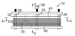
도 1은 조립 동안 라우드스피커 하우징의 측면도를 보여주는, 제 1 실시예에 따른 라우드스피커의 개략도.
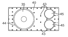
도 2는 도 1의 화살표(2)의 방향으로 도 1의 라우드스피커의 전면 플레이트의 평면도.
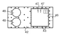
도 3은 도 1의 화살표(3)의 방향으로 도 1의 라우드스피커의 후면 플레이트의 평면도.
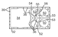
도 4는 도 1의 선(4-4) 상의 뷰와 동등한, 도 1의 라우드스피커의 시트들 중 하나의 평면도.
도 5는 도 1의 라우드스피커의 변경인 라우드스피커를 형성하기 위한 하나의 시트의 평면도.
도 6은 도 5의 라우드스피커의 전면 플레이트의 평면도.
도 7은 도 5의 라우드스피커의 후면 플레이트의 평면도.
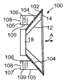
도 8은 제 1 실시예의 음향 구동기의 단면도.
도 9는 도 8의 선(9-9)상의 뷰의 도면.
도 10은 대체물을 보여주는 도 9의 뷰에 대응하는 뷰의 도면.
도 11은 도 8의 음향 구동기에 대한 제 1 변경의 단면도.
도 12는 도 8의 음향 구동기에 대한 제 2 변경의 단면도.
도 13은 플레이들로 형성되는 일 실시예에서 도 8의 음향 구동기의 일부의 상세한 단면도.
도 14는 도 13의 구조에서 사용될 수 있는 플레이트의 평면도.
도 15a는 일 대안적인 라우드스피커를 통한 단면도.
도 15b는 도 15a의 화살표(B)의 방향의 측면도.
도 15c는 선(C-C)상의 뷰에 대응하는 도 15a의 라우드스피커의 일 구성 요소의 평면도.
도 16a는 라우드스피커 하우징의 적층된 벽을 형성하는 내부 시트의 평면도.
도 16b는 도 16a의 내부 시트의 내부 표면의 평면도.
도 16c는 도 16a의 적층된 벽의 외부 시트의 외부 표면의 평면도.
도 17a는 사운드-억제 모듈의 측면도.
도 17b는 선(D-D)상의 뷰에 대응하는, 도 17a의 모듈에서 고리형 플레이트의 평면도.
도 17c는 도 17a의 모듈의 원형 단부 플레이트의 평면도.
도 18은 헤드폰의 측면도.1 is a schematic view of a loudspeaker according to a first embodiment, showing a side view of a loudspeaker housing during assembly;
Fig. 2 is a plan view of the front plate of the loudspeaker of Fig. 1 in the direction of arrow 2 in Fig.
Figure 3 is a plan view of the back plate of the loudspeaker of Figure 1 in the direction of arrow (3) in Figure 1;
4 is a plan view of one of the sheets of the loudspeaker of FIG. 1, equivalent to a view on line 4-4 of FIG. 1;
5 is a plan view of one sheet for forming a loudspeaker which is a variation of the loudspeaker of FIG.
6 is a plan view of the front plate of the loudspeaker of Fig.
7 is a plan view of the back plate of the loudspeaker of Fig.
8 is a sectional view of the acoustic driver of the first embodiment;
9 is a view of a view on line 9-9 of Fig. 8; Fig.
Figure 10 is a view of a view corresponding to the view of Figure 9 showing a replacement.
11 is a sectional view of a first modification to the acoustical driver of Fig. 8;
12 is a cross-sectional view of a second modification to the acoustical driver of Fig. 8;
Fig. 13 is a detailed cross-sectional view of a portion of the acoustic driver of Fig. 8 in one embodiment formed with the play. Fig.
Figure 14 is a plan view of a plate that may be used in the structure of Figure 13;
15a is a cross-sectional view through an alternative loudspeaker.
Fig. 15B is a side view in the direction of the arrow B in Fig. 15A. Fig.
15C is a plan view of a component of the loudspeaker of FIG. 15A corresponding to a view on line CC; FIG.
16A is a plan view of an inner sheet forming a laminated wall of a loudspeaker housing;
Figure 16b is a plan view of the inner surface of the inner sheet of Figure 16a.
Figure 16c is a plan view of the outer surface of the outer sheet of the laminated wall of Figure 16a.
17A is a side view of a sound-suppression module;
17B is a plan view of the annular plate in the module of Fig. 17A, corresponding to a view on line DD; Fig.
Figure 17c is a plan view of the circular end plate of the module of Figure 17a.
18 is a side view of a headphone;
여기서 도 1을 참조하면, 이는 라우드스피커를 제작하는 방식을 개략적으로 도시한다. 이러한 제 1 실시예에 따라, 다수의 층들(32)을 포함하는 라우드스피커(10)가 제공된다. 각각의 층(32)은 실질적으로 평탄하고, 시트 또는 얇은 층으로서 기술될 수 있다. 이는 임의의 알맞은 고체 재료, 예를 들면, 금속, 나무, 또는 나무-기반 재료 예컨대 중간 밀도 합판(MDF), 합판, 또는 플라스틱 또는 페이퍼일 수 있다. 일 예에서, 각각의 층(32)은 MDF이다. 다른 예에서, 각각의 층(32)은 플라스틱, 예를 들면, 엔지니어링 플라스틱, 예컨대 아크릴로니트릴 부타디엔 스티렌(ABS), 폴리아미드(PA), 또는 폴리에테르 에테르 케톤(PEEK)이다.Referring now to Figure 1, which schematically illustrates the manner in which a loudspeaker is made. According to this first embodiment, there is provided a
도 4에서 도시되는 바와 같이, 라우드스피커 구동기(35)가 장착될 수 있는 캐비티를 규정하기 위해 각각의 층(32)에 개구(34)가 제공된다. 홀들(36)은 또한 볼트들(38)을 수용하기 위해 각각의 층(32)에 제공된다. (볼트들(38)은, 비례적이지 않게, 도 1에서 개략적으로 도시되고, 단지 세 개의 볼트들이 도시된다.)As shown in FIG. 4, an
라우드스피커(10)는 전면 플레이트(40) 및 후면 플레이트(42)를 갖는다. 전면 플레이트(40) 및 후면 플레이트(42)는 층들(32)보다 단단하고, 이러한 실시예에서, 더 두껍고, 더 강한 재료이다. 예를 들면, 그들은 20 ㎜ 두께의 알루미늄 시트들일 수 있다. 층들(32)과 유사하게, 전면 및 후면 플레이트들(40, 42)은 볼트들(38)을 위한 홀들(43)을 갖는다. 이와 같이, 라우드스피커(10)는 전면 플레이트(40)와 후면 플레이트(42) 사이에 층들(32)의 스택을 형성하고, 볼트들(38)을 삽입하고, 너트(39)를 각각의 볼트(38)에 부속시키고, 라우드스피커(10)의 적층된 벽들이 압축되도록 모든 볼트들(38)을 조임으로써 조립된다.The
조립 동안, 볼트들(38)이 조여지기 때문에, 측벽을 두드리는 경우, 톤은 둔탁한 소리부터 훨씬 큰 피치 음까지 변경될 것이기 때문에, 결과의 노이즈의 톤은 적절한 압축력이 달성될 때에 관하여 명확한 표시를 제공한다. 요구되는 압축력의 양은 층들(32)의 재료, 개구들(34)에 의해 규정된 하우징의 깊이(종단 플레이트들(40, 42) 사이의) 및 결과의 캐비티 측벽들의 두께에 의존한다. 압축력은 단지 볼트들(38)의 종래의 죔에 의해서만 달성되는 것보다 상당히 크다.Because the
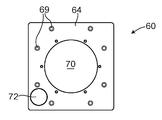
도 2에 도시된 바와 같이, 전면 플레이트(40)는 라우드스피커 구동기(35) 뒤에 장착되어 있는 구멍(44)를 규정한다. 전면 플레이트(40)는 두 개의 원형 포트들(45)을 또한 규정한다.As shown in FIG. 2, the
여기서 도 3을 참조하면, 후면 플레이트(42)는 라우드스피커 구동기(35)에 대한 전기 접속들(47)이 제공된 커버 플레이트(46)로 밀봉된 라우드스피커 구동기(35) 뒤에 정사각형 액세스 포트를 구비한다. 후면 플레이트(42)는 또한 전면 플레이트(40)를 통해 원형 포트들(45)에 맞추어 조정되는 두 개의 원형 포트들(48)을 규정한다. 3, the
여기서 도 4를 참조하면, 각각의 층(32)은 개구(34)(도시된 바와 같이 왼쪽으로)뿐만 아니라, 원형 포트들(45, 48)과 맞추어 조정하는 두 개의 원형 개구들(50)(도시된 바와 같이 오른쪽으로)을 규정한다. 각각의 층(32) 내에서 개구(34)는 두 개의 연속하는 원형 구멍들(52, 53)을 통해 개구들(50)과 통신한다. 개구(34)는 좁은 슬롯(54)을 통해 원형 구멍(52)와 통신하고, 슬롯(54)은 원형 구멍(52)와 접선적으로 맞추어 조정되고; 원형 구멍(52)는 좁은 슬롯(55)을 통해 원형 구멍(53)와 통신하고, 슬롯(55)은 원형 구멍(52) 및 원형 구멍(53) 모두와 접선적으로 맞추어 조정되고; 원형 구멍(53)는 좁은 슬롯(56)을 통해 원형 개구(50)와 통신하고, 좁은 슬롯(56)은 원형 구멍(53) 및 원형 개구(50)와 접선적으로 맞추어 조정된다. Referring now to FIG. 4, each
조립된 라우드스피커(10)에서, 원형 개구들(50)은 이와 같이 라우드스피커 구동기(35) 뒤에 개구들(34)에 의해 규정된 캐비티와 통신하는 출구 포트들을 제공한다. 그러나, 공기가 개구들(34)에 의해 규정된 캐비티와 원형 개구들(50) 중 어느 하나 사이에 흐르는 경우, 이는 원형 구멍(52)에 의해 규정된 원통형 챔버 내, 원형 구멍(53)에 의해 규정된 원통형 챔버 내, 및 원형 개구들(50)에 의해 규정된 원통형 챔버 내에 와류들이 셋 업될 것이고; 연속하는 와류들은 반대 방향들이다. 이는 가청의 음파들의 송신을 억제하는 효과를 갖는다.In the assembled
결과적으로, 사용중에, 음파들은 라우드스피커 구동기(35)의 전면으로부터 방출되지만, 라우드스피커(10)에 의해 라우드스피커 구동기(35)의 후면으로부터 발생하는 음파들이 방출되지 않는다. 이는 더 명확하고 더 정확한 사운드 재생을 제공한다. 따라서, 슬릿들(54), 구멍들(52), 슬롯(55), 구멍들(53), 슬롯들(56) 및 개구들(50)은 함께 와류 챔버들을 포함하는 두 개의 사운드-억제 덕트들을 규정한다.As a result, during use, sound waves are emitted from the front of the
라우드스피커(10)가 다수의 방식들로 변경될 수 있다는 것이 이해될 것이다. 특히, 포트들(45, 48)은 원형 개구들(50)에 대해 상이한 크기일 수 있다. 예를 들면, 포트들(45, 48)은 원형 개구들(50)보다 작은 직경일 수 있다. 이는 포트의 각각의 단부에 원주의 가장자리를 생성하기 때문에, 이는 원형 개구들(50)에 의해 규정된 원통형 포트 내에 와류들의 효과를 증가시킨다. 다른 변경에서, 전면 플레이트(40)에 포트들(45)이 존재하지만, 후면 포트(42)에 포트들(48)이 존재하지 않거나; 또는 대안적으로 후면 플레이트(42)에 포트들(48)이 존재하지만, 전면 플레이트(40)에 포트들(45)이 존재하지 않는다. It will be appreciated that the
다른 대안적인 장치에서, 스택의 하나의 부분에서 층들은 좁은 슬롯(54)을 통해 개구(34)와 통신하는 원형 구멍들(52)을 규정하고, 또한 원형 개구들(50)을 규정하지만, 원형 구멍들(52)은 원형 개구들(50)과 통신하지 않고; 스택의 다른 부분에서, 층들은 접선적으로 맞추어 조정된 슬롯을 통해 원형 개구들(50)과 통신하는 원형 구멍들(52)을 규정하지만, 원형 구멍들(52)은 개구(34)와 통신하지 않는다. 스택의 이들 두 개의 부분들은 개구(34) 및 원형 개구들(50)을 규정하고, 원형 구멍들(52)의 중심에 맞추어 조정된 작은 원형 구멍을 규정하는 층에 의해 분리된다. 이와 같이, 개구들(34)에 의해 규정된 캐비티와 개구들(50)에 의해 규정된 포트 사이의 임의의 공기 흐름은 스택의 제 1 부분에서 원형 구멍들(52) 내 와류 경로를 따를 것이고, 작은 원형 구멍을 통해 중심에서 유출하고, 이후 스택의 제 2 부분에서 원형 구멍들(52)을 통해 경로를 따르고, 원형 개구들(50)에 의해 규정된 포트들에서 와류를 형성하도록 빠져나온다. In another alternative arrangement, the layers in one portion of the stack define the
상기에 기술되는 라우드스피커(10)는 직사각형이고, 왼쪽 부분은 라우드스피커 구동기(35)를 수용하기 위한 캐비티를 제공하고, 오른쪽 부분은 와류 챔버들 및 출구 포트들을 규정한다. 유사한 라우드스피커는 사각형을 가질 수 있다는 것이 이해될 것이다.The
여기서 도 5 내지 도 7을 참조하면, 라우드스피커(60)는 전면 플레이트(64)(도 6에 도시됨)와 후면 플레이트(66)(도 7에 도시됨) 사이에 조립되는 층들(62)의 스택(도 5에 도시됨)을 구성하는 도 1에 도시된 것과 실질적으로 동일한 방식으로 형성된다. 볼트들(38)을 위해 층들(62)에서 홀들(68)이 존재하고(도 1에서와 같이); 전면 플레이트(64) 및 후면 플레이트(66) 모두에서 대응하는 홀들(69)이 존재한다. 단지 여덟 개의 홀들(68, 69)이 도시되었지만, 실제로 더 많은 이러한 홀들(68, 69), 및 이러한 더 많은 볼트들(38)이 존재할 수 있다.Referring now to Figures 5-7, the
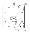
전면 플레이트(64)는 라우드스피커 구동기(35)(도 1에 도시되는) 뒤에 장착되는 중심 원형 구멍(70)를 규정하고, 도시되는 하부 왼쪽 코너에 포트(72)를 규정한다. 후면 플레이트(66)는 포트(72)와 맞추어 조정되는 포트(74)를 규정하고; 또한 라우드스피커 구동기(35)에 대해 전기 접속을 위한 소켓들(75)을 규정한다.The
각각의 층(62)은 라우드스피커 구동기(35)를 수용하기 위한 챔버를 규정하기 위해 중심 원형 구멍(76)를 규정하고; 각각의 층(62)은 포트들(72, 74)과 맞추어 조정되는 원형 개구(77)를 규정한다. 각각의 층(62) 내에 중심 원형 구멍(76)는 층(62)(도시되는)의 상부 두 개의 코너들에 인접한 두 개의 연속하는 원형 구멍들(78)을 통해 원형 개구(77)와 통신한다. 중심 원형 구멍(76)는 좁은 슬롯(80)을 통해 원형 구멍(78)와 통신하고, 슬롯(80)은 원형 구멍(78)와 접선적으로 맞추어 조정되고; 원형 구멍(78)는 좁은 슬롯(81)을 통해 원형 구멍(79)와 통신하고, 슬롯(81)은 원형 구멍들(78, 79) 모두와 접선적으로 맞추어 조정되고; 원형 구멍(79)는 좁은 슬롯(82)을 통해 원형 개구(77)와 통신하고, 좁은 슬롯(82)은 원형 구멍(79)와 원형 개구(77) 모두와 접선적으로 맞추어 조정된다.Each
조립될 때, 라우드스피커(60)는 결과적으로 상기에 기술된 라우드스피커(10)와 실질적으로 동일한 방식으로 동작한다. 원형 개구들(77)은 라우드스피커 구동기(35) 뒤에 개구들(76)에 의해 규정된 캐비티와 통신하는 출구 포트들을 제공한다. 그러나, 공기가 캐비티와 상기 출구 포트 사이에 흐르는 경우, 이는 원형 구멍들(78)에 의해 규정된 원통형 챔버 내, 원형 구멍들(79)에 의해 규정된 원통형 챔버 내, 및 원형 개구들(77)에 의해 규정된 원통형 챔버 내에 와류들을 셋 업할 것이고; 연속하는 와류들은 반대 방향들이다. 이는 가청의 음파들의 송신을 억제하는 효과를 갖는다. 따라서, 슬롯들(80, 81, 82), 구멍들(78, 79), 및 개구(77)는 함께 사운드-억제 덕트를 구성한다. When assembled, the
결과로서, 사용중에, 음파들은 라우드스피커 구동기(35)의 전면으로부터 방출되지만, 라우드스피커 구동기(35)의 후면으로부터 발생하는 음파들이 라우드스피커(60)에 의해 방출되지 않는다. 이는 더 명확하고 더 정확한 사운드 재생을 제공한다. 라우드스피커(60)는 최소 볼륨의 라우드스피커들을 제작할 때 더 적절한 더 소형의 설계를 제공한다. 일 예에서, 치수들은 420 ㎜ × 420 ㎜이고, 180 ㎜ 두께이고; 다른 예에서, 치수들은 250 ㎜ × 250 ㎜이고, 280 ㎜ 두께이다.As a result, in use, the sound waves are emitted from the front of the
본 발명에 따라 제작된 라우드스피커들이 넓은 범위의 상이한 적용들을 갖고, 예를 들면, 그들은 전문가용 오디오, 가정용 오디오, 휴대용 오디오, 헤드폰들, 랩탑들, 이동 전화들을 포함하여 넓은 범위의 상이한 분야들에서 적용을 위해 매우 작은 것으로부터 매우 큰 것까지, 임의의 형태, 크기, 또는 주파수 범위의 라우드스피커들에 대해 사용될 수 있다는 것이 예상된다. 이점들이 제공되는 다른 라우드스피커 필드들은 다음을 포함할 수 있다: 자동차-단단한 형상들이 임의의 비용 불이익 없이, 카 오디오 품질을 개선하기 위해, 특정한 또는 제한된 공간들 내에 맞도록 제작될 수 있다. 이들 디바이스들은 또한 더 얇고, 동시에 사운드 품질을 개선하고, 무게 및 비용을 감소시킬 수 있다. 항공기 - 이는 품질에서 및 감소된 무게 모두에서 항공기 사운드 시스템들을 개선한다. 산업 및 공공 공간- 큰 고전력 라우드스피커들은 감소된 제작 비용으로 사운드 품질 및 수명에서 개선될 수 있다. 랩탑들, 텔레비전 및 휴대용 엔터테인먼트 디바이스들 - 증가된 사운드 품질 및 감소된 무게를 갖는 저 비용 제품. 보트들-물 및 소금으로부터의 문제들은 재료들의 적절한 선택에 의해 감소될 수 있다. 화재 및 도난 경보기들 및 대피 스피커들-내화성 및 내열성 재료는 내화성 및 부정 조작 방지 라우드스피커를 생산하기 위해 사용될 수 있다.The loudspeakers manufactured in accordance with the present invention have a wide range of different applications, for example they can be used in a wide range of different fields, including professional audio, home audio, portable audio, headphones, laptops, It is expected that it can be used for loudspeakers of any shape, size, or frequency range, from very small to very large for application. Other loudspeaker fields for which advantages may be provided include: automotive-rigid features can be tailored to fit within specific or limited spaces, to improve car audio quality, without any cost penalty. These devices can also be thinner, at the same time improving sound quality, and reducing weight and cost. Aircraft - this improves aircraft sound systems both in quality and in reduced weight. Industrial and public spaces - Large high power loudspeakers can be improved in sound quality and lifetime with reduced production costs. Laptops, televisions and portable entertainment devices - low cost products with increased sound quality and reduced weight. Problems from boats - water and salt can be reduced by proper selection of materials. Fire and burglar alarms and evacuation loudspeakers - Refractory and heat resistant materials can be used to produce fireproof and tamper-proof loudspeakers.
다른 변동들 및 변경들은 당업자에게 명백할 것이다. 이러한 변동들 및 변경들은 이미 알려지고 여기에 기술된 특징들 대신에 또는 그에 더하여 사용될 수 있는 동등한 및 다른 특징들을 포함할 수 있다. 개별적인 실시예들의 내용에 기술되는 특징들은 단일 실시예에서 조합하여 제공될 수 있다. 반대로, 단일 실시예의 내용에 기술되는 특징들은 또한 개별적으로 또는 임의의 적절한 서브 조합으로 제공될 수 있다. Other variations and modifications will be apparent to those skilled in the art. Such variations and modifications may include equivalent and other features that may be used in lieu of or in addition to features already known and described herein. The features described in the context of individual embodiments may be provided in combination in a single embodiment. Conversely, features described in the context of a single embodiment may also be provided individually or in any suitable subcombination.
하나의 이러한 변경은 전면 플레이트(40, 64)의 또는 후면 플레이트(42, 66)의 내부 표면들, 즉, 층들(32, 62)에 향하는 이들 표면들에 관한 것이다. 층(32, 62)과 접촉하는 내부 표면들의 이들 부분들은 층들(32, 62)이 압축하에 있다는 것을 보장하기 위해 단단해야 한다. 구멍(52, 53; 78, 79) 또는 슬롯(54, 55, 56; 80, 81, 82)에 맞추어 조정되는 내부 표면들의 이들 부분들은 그렇게 단단해야 하지 않아서, 이들 부분들은 인접하는 층(32, 62)의 형상을 플레이트의 두께의 일 부분과 매칭하여 규격화될 수 있다. 예를 들면, 플레이트들(40, 42, 64, 66)은 20 ㎜ 두께이지만, 이들 부분들은 5 ㎜ 또는 10 ㎜ 두께까지 규격화될 수 있다. 이는 라우드스피커(10, 60)의 전체 무게를 감소시킨다.One such variation relates to the inner surfaces of the
라우드스피커들(10, 60)은 프레임 내에 장착된 코일과 같은 전기 액추에이터와 함께 판지 원뿔과 같은 움직일 수 있는 라우드스피커 요소를 포함하는 알려진 형태일 수 있는 구동기(35)를 통합한다. 프레임은 종래에, 그의 움직임이 방해되지 않도록 움직일 수 있는 라우드스피커 요소 뒤에 큰 구멍들을 규정하는, 일반적으로 원뿔 형상의 케이지형 개방 프레임워크로 형성된다. 본 발명의 일 대안적인 양태에서, 사운드-억제 덕트는 구동기의 프레임 내에 통합될 수 있다. 이는, 라우드스피커들(10, 60)에서와 같이 하우징 내에 사운드-억제 덕트의 제공을 대신하거나 또는 그에 추가할 수 있다.The
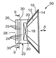
그래서, 여기서 도 8을 참조하면, 음향 구동기(90)는 원뿔(12)이 절단된 원뿔형 프레임(16)에 부착되는 그의 더 넓은 단부에서 플렉시블 주변 플랜지(14)를 갖는 경량의 원뿔(12)을 포함한다. 원뿔(12)의 더 좁은 단부는 프레임(16)의 더 좁은 단부에 갖는 고리형 자석(18)의 자기장 내에 코일(도시되지 않음)을 지녀서, 코일에서 교호하는 전류는 원뿔(12)이 화살표(A)로 표시된 바와 같이 앞뒤로 이동하게 한다. 이들 특징들은 프레임(16)의 설계를 제외하고 종래의 기술이다.8, the
종래의 음향 구동기에서, 절단된 원뿔형 프레임은 다수의 큰 구멍들을 규정하는 케이지형 구조이고, 그래서 원뿔(12)은 두 방향들로 자유롭게 이동하는 것이 자유롭다. 도 8의 음향 구동기(90)에서, 절단된 원뿔형 프레임(16)은, 고리형 자석(18)의 에지 주위에 균등하게 이격된 단지 네 개의 작은 구멍들(20)을 규정하는, 연속적인 절단된 원뿔형 표면이고, 각각의 구멍(20)는 음향 구동기(10)의 직경의 약 20분의 1이다(이들 구멍들(20) 중 단지 두 개가 도 8에 도시된다).In a conventional acoustic driver, the truncated conical frame is a cage-like structure defining a number of large holes, so that the
이들 구멍들(20)은 고리형 자석(18)과 동심원이고 그를 둘러싸는 절단된 원뿔형 프레임(16)의 후면에 부착된 원통형 사운드-억제 챔버(22)와 통신하다. 원통형 사운드-억제 챔버(22)는 이 예에서, 세 개의 배플판들(25)에 의해 네 개의 연속하는 원통형 챔버들(24)로 세분되고, 중심 출구 구멍(28)를 갖는 종단 플레이트(26)를 갖는다.These
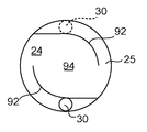
여기서 도 9를 참조하면, 각각의 배플판(25)은 하나의 에지 근처에 원형 구멍(30)(배플판(25)의 직경의 약 10%와 20% 사이의 직경의)를 규정하고, 연속하는 배플판들(25)의 구멍들(30)은 반대측들상에, 서로 직경 방향으로 반대로 있다(도 9에 파선들로 도시된 바와 같이). 여기서, 원뿔(12)의 움직임에 의해 원통형 사운드-억제 챔버(22)를 통한 임의의 공기 흐름은 작은 구멍들(30)을 통해 및 이후 훨씬 더 큰 원통형 챔버들(24)로 반복적으로 흐를 공기를 요구한다. 이는 음파들을 억제하는 효과를 갖는다. 이러한 예에서, 출구 구멍(28)는 구멍들(30)의 각각보다 크고, 종단 플레이트(26)의 중심에 있고; 변경에서, 출구 구멍(28)는 마지막 원통형 챔버(24)로 통하는 구멍(30)에 직경 방향으로 반대이다.9, each
각각의 원통형 챔버(24)는 원통형 챔버(24)의 반대측들로부터 밖으로 돌출하는 두 개의 부분적으로 아치형 배플들(92)(도 8에 도시되지 않음)로 세분되고, 아치형 부분들은 원통형 챔버(24)의 벽과 동심원에 있어서, 아치형 부분들은 함께 원통형 챔버(24)내 동심원에 있는 원통형 공간(94)을 규정한다. 입구 구멍(30) 및 출구 구멍(30)(파선들로 표시됨)는 각각의 부분적으로 아치형 배플들(92)에 의해 원통형 공간(94)으로부터 분리된다.Each
여기서, 사용시, 입구 구멍(30)로부터 출구 구멍(30)로의 공기 흐름은 배플들(92)의 아치형 부분들과 원통형 챔버(24)의 동심원 벽 사이에 규정된 곡선형 경로들을 통해 흘러야 하고, 또한 원통형 공간(94)을 통해 흘러야 한다. 입구 구멍(30)로부터 원통형 공간(94)으로의 공기 흐름은 시계 방향으로(도시된 바와 같이) 흘러가야 하고, 반면에 출구 구멍(30) 쪽으로의 원통형 공간(94) 밖으로의 공기 흐름은 시계 반대 방향으로 흘러가야 한다. 원통형 공간(94) 내 공기 흐름은 와류를 형성하기 쉽고, 유입 속도가 높을수록 와류를 형성할 더 높은 경향성을 갖는다; 그러나, 와류는 유출을 억제한다. 그래서, 배플들(92)은 또한 사운드 송신을 억제한다.Here, in use, the air flow from the inlet opening 30 to the
여기서 도 10을 참조하면, 원통형 챔버(24) 내 장치에 대한 변경에서, 상기에 기술되는 원통형 챔버(24)의 벽과 동심원을 이루는 부분, 및 벽에 연결하기 위한 더 큰 반경의 곡선 부분(97)을 갖는 그들의 길이 전체가 곡선을 이루는 두 개의 아치형 배플들(96)이 존재할 수 있다 .Referring now to FIG. 10, in a variation on the device in the
여기서 도 11을 참조하면, 이는 음향 구동기(90)에 대한 변경인 음향 구동기(100)를 도시하고, 동일한 특징들은 동일한 참조 번호들로 나타내진다. 음향 구동기(100)는 원뿔(12)이 절단된 원뿔형 프레임(102)에 부착되는 그의 더 넓은 단부에 플렉시블 주변 플랜지(14)를 갖는 경량의 단단한 원뿔(12)을 포함한다. 원뿔(12)의 더 좁은 단부는 프레임(102)의 더 좁은 단부에 전달된 고리형 자석(18)의 자기장 내에 코일(도시되지 않음)을 지녀서, 코일에서 교호하는 전류는 원뿔(12)이 화살표(A)로 표시된 바와 같이 앞뒤로 이동하게 한다. 상기 언급된 바와 같이, 이들 특징들은 프레임(102)의 구조를 제외하고 종래의 것이다.Referring now to FIG. 11, which illustrates an
도 11의 음향 구동기(100)에서, 절단된 원뿔형 프레임(102)은 반대측들상에 단지 두 개의 작은 구멍들(104)을 규정하는 연속하는 절단된 원뿔형 표면이고, 각각의 구멍(104)는 음향 구동기(100)의 직경의 약 20분의 1이다. 이들 구멍들(104)은 절단된 원뿔형 프레임(102)의 후면에 부착된 두 개의 원통형 사운드-억제 챔버들(105)과 통신한다. 각각의 원통형 사운드-억제 챔버(105)는, 연속하는 배플판들(106)에 의해 다수의 연속하는 원통형 챔버들로 세분되고, 중심 출구 구멍(108)를 갖는 종단 플레이트(107)를 갖기 때문에, 상기에 기술된 원통형 사운드-억제 챔버(22)의 구조와 동등한 구조를 갖는다. 각각의 배플판(106)은 구멍(109)를 규정하고, 구멍들은 연속하는 배플판들(106)에 엇갈리게 배열된다. 연속하는 원통형 챔버들의 각각 내에 도 9 또는 도 10에 도시된 배플들(92 또는 96)이 존재한다. 이러한 원통형 사운드-억제 챔버(105)는 따라서 원뿔(12)의 후면으로부터 사운드 송신을 억제하는 원통형 사운드-억제 챔버(22)와 실질적으로 동일한 방식으로 동작한다.In the
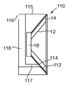
여기서 도 12를 참조하면, 이는 음향 구동기(90)에 대한 대안적인 변경인 음향 구동기(110)를 도시하고, 유사한 특징들은 동일한 참조 번호들로 나타내진다. 음향 구동기(110)는 원뿔(12)이 절단된 원뿔형 프레임(112)에 부착되는 그의 더 넓은 단부에 플렉시블 주변 플랜지(14)를 갖는 경량의 단단한 원뿔(12)을 포함한다. 원뿔(12)의 더 좁은 단부는 프레임(112)의 더 좁은 단부에 지닌 고리형 자석(18)의 자기장 내에 코일(도시되지 않음)을 지녀서, 코일에서 교호하는 전류가 원뿔(12)이 앞뒤로 이동하게 한다. 상기 언급된 바와 같이, 이들 특징들은 (프레임(112)의 구조를 제외하고) 종래의 기술이다.Referring now to FIG. 12, which illustrates an
절단된 원뿔형 프레임(112)은 하나의 측면에서 단일의 작은 구멍(114)를 규정하는 연속하는 절단된 원뿔형 표면이다. 구멍(114)는 음향 구동기(110)의 직경의 10분의 1과 20분의 1 사이이다. 음향 구동기(110)는 후면의 상부에 출구 구멍(116)를 포함하는 하우징(115) 내에 장착된다(도시된 바와 같이). 파이프(117)는 하우징(115) 내 구멍(114)와 사운드-억제 챔버(118) 사이에 통신하고, 사운드-억제 챔버(118)는 출구 구멍(116)와 통신한다. 사운드-억제 챔버(118)의 상세한 내부 구조는 도시되지 않지만, 이는 사운드 송신을 억제하기 위한 와류 챔버들을 포함하고, 예를 들면, 이는 상기에 기술되는 와류 흐름을 야기하기 위해 아치형 배플들(92 또는 96)과 결합하는, 사운드-억제 챔버들(22)에 관하여 기술되는 다수의 배플판들을 포함할 수 있다. The truncated
따라서, 각각의 경우에, 원통형 사운드-억제 챔버(22)의, 또는 배플들(92 또는 96)을 갖는 원통형 사운드-억제 챔버들(105)의 효과는 음파들이 출구 구멍(28, 108, 또는 116)를 통해 빠져나오는 것을 억제하는 것이다. 그럼에도 불구하고 원뿔(12)의 후면과 주변들 사이에 공기 흐름에 대한 제한이 없어서, 원뿔(12)의 움직임들은 압력 변동들에 의해 억제되지 않는다. Thus, in each case, the effect of the cylindrical sound-
음향 구동기들(90, 100, 110)은, 완전히 밀봉된 하우징에 장착되거나 종래의 포트를 갖는 하우징에 장착된 음향 구동기와 비교될 때, 더 명확하고 더 정확한 사운드를 생성하는 것이 발견되었다. 이는, 밀봉된 하우징에 의해, 원뿔(12) 뒤의 공기가 압축되고, 이는 원뿔(12)의 움직임을 억제하기 때문이다; 반면에 종래의 포트에 의해, 사운드는 포트로부터 빠져나오고 음향 구동기의 전면으로부터의 사운드와 간섭할 수 있다.It has been found that the
음향 구동기들(90, 100, 110)은, 하우징이 주변과 통신을 위한 포트를 제공하는 한, 종래의 라우드스피커 하우징 내에 장착될 수 있고; 사실상 임의의 이러한 하우징 없이 사용될 수 있다. 음향 구동기들(90, 100)은 또한 구동기(35)를 대신하여 상기에 기술된 라우드스피커들(10, 60)의 하우징과 같은 하우징에 사용될 수 있다. 이러한 경우, 원뿔(12)의 후면으로부터의 사운드는 사운드-억제 챔버(22)(또는 105)에 의해 먼저 억제되고; 이후 라우드스피커(10)에서 구멍들(52, 53) 및 개구들(50)에 의해 규정된 것들과 같이 하우징의 외부에 이어지는 덕트에서 와류 챔버들에 의해 또한 억제된다.The
음향 구동기들(90, 100, 110)은 종래의 재료들로 구성될 수 있다. 예를 들면, 프레임(16)은 캐스트 알루미늄의 얇은 벽으로 구성될 수 있고, 반면에 원통형 사운드-억제 챔버(22)는 함께 용접된 금속 시트들로 구성될 수 있다. 원통형 사운드-억제 챔버(22)의 벽들 및 배플들(25)은 상당한 진동을 겪지 않도록 충분히 단단해야 한다는 것이 이해될 것이다. 상기 제한을 조건으로 하면, 원통형 사운드-억제 챔버(22)의 외부 형상이 사운드 송신에 영향을 미치지 않기 때문에, 벽 두께들은 중요한 파라미터가 아니다.The
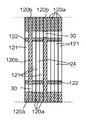
여기서 도 13을 참조하면, 일 대안으로서, 원통형 사운드-억제 챔버(22)(또는 원통형 사운드-억제 챔버(105))는 플레이트들(120a, 120b)의 스택으로 구성될 수 있고, 플레이트들(120a)은 원통형 챔버들(24)을 규정하기 위해 맞추어 조정된 원형 구멍들(121)을 규정하고, 플레이트들(120b)은 구멍들(30)을 규정하고, 그래서 배플들(25)에 대응한다. 플레이트들(120)은 적층된 통합 구조로 함께 고정된다. 예를 들면, 플레이트들은 함께 접합될 수 있거나, 또는 볼트들을 사용하여 함께 고정될 수 있다.Referring now to FIG. 13, in one alternative, a cylindrical sound-suppression chamber 22 (or cylindrical sound-suppression chamber 105) may be comprised of a stack of
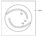
이러한 경우에, 원통형 챔버들(24)은 도 5의 배플들(96)과 동등한 아치형 배플들을 갖는다. 이와 같이, 원통형 챔버(24)의 부분을 규정하기 위해 원형 구멍(121)를 규정하는 각각의 플레이트(120a)는 돌출하는 스트립들(122)과 통합된다. 여기서 도 14를 참조하면, 원형 구멍(121)를 규정하는 플레이트(120a)의 평면도가 도시된다.; 플레이트(120a)는 또한 돌출하는 곡선형 스트립들(122)을 규정해서, 플레이트들(120a)이 함께 적층될 때, 곡선형 스트립들(122)은 상기에 기술된 바와 같이 아치형 배플들(96)을 규정한다. 이러한 예에서, 외부 형상이 대신 원형과 같은 상이한 형상이라는 것이 이해될지라도, 플레이트(120a)는 그의 외부 형상에 관하여 정사각형이다.In this case, the
각각의 플레이트(120)는 실질적으로 평탄하고, 시트 또는 얇은 층으로서 기술될 수 있다. 이는 임의의 알맞은 고체 재료, 예를 들면, 금속, 목재, 또는 중간 밀도 합판(MDF)과 같은 목재 기반 재료, 합판, 또는 플라스틱 또는 페이퍼일 수 있다. 일 예에서, 각각의 플레이트(80)은 MDF이다. 다른 예에서, 각각의 플레이트(120)는 플라스틱, 예를 들면, 엔지니어링 플라스틱, 예컨대 아크릴로니트릴 부타디엔 스티렌(ABS), 폴리아미드(PA), 또는 폴리에테르 에테르 케톤(PEEK)이다.Each plate 120 is substantially planar and can be described as a sheet or a thin layer. It may be any suitable solid material, for example, a wood-based material such as metal, wood, or medium density plywood (MDF), plywood, or plastic or paper. In one example, each
플레이트들(120)은 플레이트들(120)보다 더 견고한 전면 플레이트와 후면 플레이트 사이에 적층될 수 있고, 더 단단한 재료일 수 있다. 예를 들면, 그들은 알루미늄의 20 ㎜ 두께 시트들일 수 있다. 플레이트들(120) 및 전면 플레이트 및 후면 플레이트는 또한 볼트들을 위해 맞추어 조정된 홀들이 제공될 수 있다. 이와 같이, 원통형 사운드-억제 챔버(22)는 전면 플레이트와 후면 플레이트 사이에 플레이트들(120)의 스택을 형성하고, 볼트들을 삽입하고, 너트를 각각의 볼트에 부속시키고, 원통형 사운드-억제 챔버(22)의 적층된 벽들이 압축되도록 모든 볼트들을 조임으로써 조립될 수 있다.The plates 120 may be stacked between the front plate and the back plate that are more rigid than the plates 120 and may be a more rigid material. For example, they may be 20 mm thick sheets of aluminum. The plates 120 and the front and rear plates may also be provided with holes adjusted for the bolts. As such, the cylindrical sound-
조립 동안, 볼트들이 조여질 때, 측벽상을 톡톡 치는 경우, 결과의 노이즈의 톤은, 톤이 둔탁한 두드림 소리로부터 더 높은 피치 음까지 변경하기 때문에, 적절한 압축력이 도달되었을 때, 명확한 표시를 제공한다. 요구되는 압축력의 양은 플레이트들(120)의 재료, 구조(종단 플레이트들 사이)의 깊이, 및 개구들(121)에 의해 규정된 결과의 캐비티의 측벽들의 두께에 의존한다. 바람직한 압축력은 볼트들의 종래의 죔에 의해서만 달성되는 것보다 상당히 크다. 그러나, 이러한 높은 압축력이 이러한 환경에서 적용되는 것이 필수적이지는 않다. During assembly, when tapping on the side walls when the bolts are tightened, the tone of the resulting noise provides a clear indication when the appropriate compressive force is reached, since the tone changes from a blunt sound to a higher pitch sound . The amount of compressive force required depends on the material of the plates 120, the depth of the structure (between the end plates), and the thickness of the resulting sidewalls of the cavity defined by the
상기 기술된 바와 같이, 사운드-억제 와류 챔버들을 포함하는 덕트가 라우드스피커들(10, 60)에서와 같이 적층된 구조의 하우징에 포함될 수 있다. 또한, 사운드-억제 와류 챔버들을 포함하는 덕트는 음향 구동기들(90, 100, 110)에서와 같이 라우드스피커 원뿔(12)을 지원하는 프레임과 결합될 수 있다. 사운드-억제 와류 챔버들을 포함하는 덕트가 라우드스피커에 통합될 수 있는 다수의 다른 방식들이 존재한다. 예를 들면, 포트가 제공된 종래의 박스형 라우드스피커 하우징의 경우에, 원통형 사운드-억제 챔버(22 또는 105)는 포트에 장착될 수 있고, 그래서 임의의 공기 흐름은 사일런싱 챔버(22, 105)를 통과해야 한다. 상기에 기술된 바와 같이, 원통형 사운드-억제 챔버(22, 105)는 직렬의 다수의 와류 챔버들을 규정한다. 사실상, 이러한 라우드스피커 하우징이 복수의 포트들이 제공되는 경우, 각각의 포트는 이러한 사운드-억제 챔버(22 또는 105)가 제공될 것이다.As described above, ducts including sound-suppressing vortex chambers may be included in the housing of a stacked structure, such as in
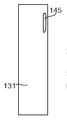
여기서 도 15a 내지 도 15c를 참조하면, 다른 변동들에서 라우드스피커(130)는 포트들이 제공될 수 있고, 각각의 포트는 하나 이상의 그의 벽들에서 각각의 와류 챔버를 포함한다. 예를 들면, 박스형 하우징은 플레이트들 사이에 규정된 와류 챔버들을 갖고, 함께 결합된 두 개의 플레이트들로 구성된 벽들의 적어도 부분들을 포함할 수 있다. 라우드스피커(130)는 MDF 재료의 시트들로 구성된 직사각형 하우징을 포함하고; 두 개의 측벽들(131), 기저벽(132), 및 상부 벽(133)은 직사각형 인클로저를 형성하고 홀들(135)을 통해 삽입된 볼트들(도시되지 않음)에 의해 전면 플레이트(134)와 후면 플레이트(도시되지 않음) 사이에 고정된다. 전면 플레이트(134)는 음향 구동기들(도시되지 않음)을 지원하기 위한 두 개의 원형 구멍들(136, 137)을 규정한다. Referring now to FIGS. 15A-15C, in other variations, the
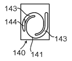
하부 코너들은 정사각형 섹션 바들(138)에 의해 보강된다. 각각의 측벽(131)의 상부는 측벽(131)상에 접착되고 하우징의 상부 모서리로 연장하는 내부 플레이트(140)를 포함한다. 측벽(131)을 마주보는 내부 플레이트(140)의 표면에 형성된 홈부(141)가 존재하고, 이러한 홈부(141)는 일반적으로 원형 캐비티(142) 및 직경으로 반대 위치들에서 캐비티(142)에 연결된 두 개의 아치형 채널들(143)을 규정하고, 두 개의 채널들(143)은 도 15c에 도시된 바와 같이 일반적으로 반 시계 방향으로 연장한다. 하나의 채널(143)은 내부 플레이트(140)의 두께를 통해 슬롯 형상 포트(144)를 통해 하우징의 내부와 통신한다. 다른 채널(143)은 측벽(131)을 통해 슬롯 형상 포트(145)를 통해 통신한다.The lower corners are reinforced by square section bars 138. The top of each
따라서, 하우징의 각각의 측면상에 슬롯 형상 포트(144), 홈부(141), 및 슬롯 형상 포트(145)를 통해 하우징의 내부와 외부 사이의 공기 흐름 경로가 존재한다는 것이 이해될 것이다. 각각의 흐름 경로는 임의의 공기의 흐름을 통해 금지할 와류를 생성하기 쉬워지도록 정렬되는 아치형 채널들(143) 및 원형 캐비티(142)를 포함한다. 따라서, 각각은 사운드-억제 덕트의 역할을 한다. 따라서, 라우드스피커(130)는 동시에 동작하는 두 개의 사운드-억제 덕트들을 통합한다. Thus, it will be appreciated that on each side of the housing there is an air flow path between the interior and exterior of the housing through the slot-shaped
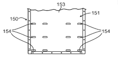
여기서 도 16a 내지 도 16c를 참조하면, 일 대안으로, 라우드스피커 하우징(150)은 다수의 이러한 사운드-억제 와류들을 가질 수 있다. 라우드스피커 하우징(150)은 두 개의 시트들, 함께 접합된, 내부 시트(152) 및 외부 시트(153)로 구성되는, 적층된 구성의 벽(151)을 포함한다. 두 개의 시트들은 예를 들면, MDF 또는 합판이거나, 플라스틱일 수 있다. 도 16c에 도시된 외부 시트(153)는 슬롯 형상 포트들(154)의 어레이를 규정한다. 도 16b에 도시된 내부 시트(152)는 포트들(154)과 맞추어 조정되지 않은 슬롯 형상 포트들(155)의 어레이를 규정한다. 도 16a에 도시된 바와 같이, 외부 시트(153)를 마주보는 내부 시트(152)의 표면에 형성된 다수의 홈부들(156)이 존재한다. 각각의 홈부(156)는, 그것이 일반적으로 원형 캐비티(157), 및 직경으로 반대 위치들에서 캐비티(157)에 연결된 두 개의 나선형 채널들(158)을 규정하기 때문에, 상기에 기술된 홈부들(141)의 형상과 유사한 형상을 갖는다. 각각의 홈부(156)에 관련하여, 하나의 채널(158)의 단부는 포트(155)와 통신하고, 다른 채널(158)의 단부는 외부 시트(153)의 포트(154)와 통신한다. Referring now to Figures 16a-c, in one alternative, the
따라서, 동작시, 슬롯 형상 포트들(145), 홈부들(156), 및 벽(151)을 따라 정렬되는 슬롯 형상 포트들(154)을 통해 하우징의 내부와 외부 사이에 다수의 공기 흐름 경로들이 존재한다. 모든 이들 공기 흐름 경로들은 평행하다. 각각의 이러한 흐름 경로는, 임의의 공기 흐름이 공기의 흐름을 통해 억제할 와류를 생성하기 쉬울 아치형 채널들(158) 및 원형 캐비티(157)를 포함한다. 따라서, 각각의 이러한 흐름 경로는 사운드-억제 덕트의 역할을 한다.Thus, in operation, a plurality of air flow paths between the interior and exterior of the housing through the slot shaped
병렬의 이러한 사운드-억제 덕트들의 어레이는 하우징(150)의 하나보다 많은 벽에 제공될 수 있다는 것이 또한 이해될 것이다. 예를 들면, 이러한 사운드-억제 덕트들은 하우징(150)의 뒷벽 및 두 개의 측벽들에 제공될 수 있다. 벽(151)에서 사운드-억제 덕트들이 규칙적인 어레이로 있는 것으로 기술되지만, 그들은 대신 임의의 적절한 방식으로 정렬될 수 있다는 것이 또한 이해될 것이다.It will also be appreciated that an array of such sound-suppressing ducts in parallel may be provided on more than one wall of the
홈부들(141, 156)이 기술된 바와 같이 내부 시트(140 또는 152)의 외부면에 형성될 수 있지만, 대안적으로 외부 시트(131 또는 153)의 내부면에 형성될 수 있다는 것이 또한 이해될 것이다. 대안적으로, 매칭하는 홈부들은 내부 시트(140 또는 152) 및 외부 시트(131 또는 153) 모두의 반대면들 상에 형성된다. It will also be appreciated that the
하우징(150)을 이용하는 라우드스피커는 종래의 구동기를 포함할 수 있거나, 대안적으로 사운드-억제 챔버(22 또는 105)를 포함하는 구동기(90) 또는 구동기(100)를 포함할 수 있고, 그래서 원뿔(12)의 후면으로부터 오는 임의의 사운드는 사운드-억제 챔버(22 또는 105)를 통과할 뿐만 아니라 홈부들(156)에 의해 제공된 사운드-억제 덕트들을 통과해야 한다는 것이 이해될 것이다. 유사하게, 구동기(90 또는 100)는 하우징(130) 내에 장착되거나, 또는 라우드스피커(10 또는 60)에서 구동기(35)를 대신하여 사용될 수 있다.The loudspeaker utilizing the
라우드스피커(130) 및 라우드스피커 하우징(150)에서, 사운드-억제 덕트는 벽(131 또는 151)를 통해 구조의 외부로 연장한다. 라우드스피커(10)에서, 사운드-억제 덕트들은 구조의 벽에서 포트(45)와 통신하는 개구(50)와 통신한다. 사운드-억제 덕트들이 상기 외부 포트와 통신하는 사운드-억제 덕트들을 정렬함으로써 출구 포트(예를 들면, 뒷벽 또는 측벽에서)을 갖는 종래의 라우드스피커 하우징에 제공될 수 있다는 것이 이해될 것이다. 이는, 예를 들면, 라우드스피커 하우징(130)과 같지만, 벽들을 통한 사운드-억제 덕트들 없이, 대신에 예를 들면, 후면 또는 측벽에 적어도 하나의 출구 포트를 갖는 박스형 라우드스피커 하우징에 적용가능할 것이다. In the
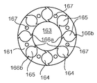
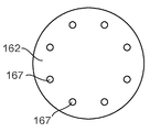
예를 들면, 도 17a 내지 도 17c를 참조하면, 사운드-억제 모듈(160)이 도시된다. 사운드-억제 모듈(160)은 원통 형상이고, 고리형 플레이트들 및 원형 후면 플레이트(162)(도 17c를 참조)의 스택으로 구성되고; 이러한 예에서, 각각의 플레이트(161, 162)는 외부 직경 100 ㎜이고, 각각의 고리형 플레이트(161)는 직경 50 ㎜의 중심 원형 구멍(163)을 규정한다(도 17b를 참조). 원형 후면 플레이트(162)는, 예를 들면, 1 ㎜와 4 ㎜ 사이의 두께인 강철일 수 있고, 반면에 고리형 플레이트들(161)은 엔지니어링 플라스틱과 같은 덜 단단한 재료일 수 있다. 일 예에서, 그들은 두께 10 ㎜이고, 열가소성 수지인, 폴리옥시메틸렌(예를 들면, DelrinTM)이다. 각각의 고리형 플레이트(161)는 여덟 개의 사운드-억제 덕트들(164)을 규정하고, 각각의 덕트(164)는 원형 홈부(164)에 접선 방향인 노치들(166a, 166b)에 의해 플레이트(161)의 내부 및 외부 에지들에 연결된 원형 홈부(165)에 의해 규정된다. 사운드-억제 덕트들(164), 즉 원형 홈부들(165), 및 노치들(166a, 166b)은 고리형 플레이트(161)의 두께의 어느 정도까지 연장하는 균일한 깊이이다. 각각의 고리형 플레이트(161)는 또한 볼트들(168)을 고정하기 위한 여덟 개의 홀들(167)(도 17b를 참조)을 또한 규정하고, 이들 홀들(168)은 고리형 플레이트(161)를 통해 및 후면 플레이트(162)를 통해 오른쪽으로 연장한다.For example, referring to Figs. 17A-17C, a sound-
사운드-억제 모듈(160)은 후면 플레이트(162) 및 고리형 플레이트(161)를 벽상에 고정하는 볼트들(168), 및 벽을 통한 포트에 맞추어 조정된 중심 원형 구멍들(163)을 갖고 라우드스피커 하우징의 벽(도시되지 않음)에 고정된다. 사운드-억제 모듈(60)은 보통 벽의 내부에 고정되고, 그래서, 이는 하우징 내에 있고 그래서 보이지 않는다. 따라서, 모듈(60)은 모두가 공기 흐름을 병렬로 정렬되는, 56 개의 사운드-억제 덕트들(164)을 규정한다. 노치들(166a, 166b)의 방향은, 임의의 공기 흐름이 발생하는 경우, 와류가 각각의 원형 홈부(165) 내에 형성되고, 그래서 사운드-억제 모듈(160)은 사운드 전파를 억제하는 것을 보장한다.The sound-
사운드-억제 덕트들(164)의 수가 함께 적층되는 고리형 플레이트들(161)의 수를 변경함으로써 변경될 수 있다는 것이 이해될 것이다. 각각의 고리형 플레이트(161)가 상이한 수의 사운드-억제 덕트들(164)을 규정하는 것이 또한 이해될 것이다. 또한, 플레이트들(161, 162)은 상이한 직경 또는 사실상 상이한 외부 또는 내부 형상이다. 다른 변경에서, 사운드-억제 덕트들(164)은 함께 고정되는 고리형 플레이트들상에 매칭하는 홈부들로 규정된다(인접한 플레이트들상의 홈부들은 평면에서 보여질 때 미러 이미지들이다).It will be appreciated that the number of sound-suppressing
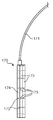
사운드-억제 모듈(160)은 상기 기술되는 라우드스피커 하우징의 벽에 고정될 수 있지만, 대안적으로 이러한 사운드-억제 모듈은 그 자체가 사운드-생성 디바이스를 위한 하우징을 규정할 수 있다. 이는, 예를 들면, 하우징 자체가 원통형일 수 있는 경우 적절하다. 예를 들면, 여기서 도 19을 참조하면, 이는 한 쌍의 헤드폰들을 형성하기 위해, 곡선형 지지대(171)를 통해 제 2 헤드폰(도시되지 않음)에 접속된 헤드폰(170)을 도시한다. 헤드폰(170)은, 각각이 상기에 기술된 사운드-억제 덕트들(164)과 실질적으로 동일한 형상의 사운드-억제 덕트들을 규정하는 두 개의 고리형 플레이트들(172) 사이에 고정되고, 노치들(173)을 통해 헤드폰(170)의 외부와 통하는 얇은 구동기(도시되지 않음)를 포함한다. 헤드폰(170)은 또한 고리형 플레이트들(172)의 중심 홀의 직경에 매칭하도록 원형 중심 홈부를 규정하고, 인접한 고리형 플레이트(172)의 홈부들 및 노치들(173)에 매칭하도록 미러 이미지 홈부들 및 노치들(173)을 규정하는원형 출구 플레이트(174)를 포함한다. 예로서, 고리형 플레이트(172) 및 출구 플레이트(174)는 알루미늄일 수 있고, 그들은 볼트들에 의해 함께 유지될 수 있다(도시되지 않음).The sound-
따라서, 사용중, 헤드폰(170)의 얇은 구동기의 앞뒤 영역들에서 압력 변동들은, 공기가 다수의 사운드-억제 덕트들을 통해 흐르기 때문에 억제되지만, 원형 챔버들 및 노치들(173)은 임의의 공기 흐름이 사운드 전파를 억제하는 와류를 생성할 것임을 보장한다.Thus, during use, the pressure variations in the front and rear regions of the thin driver of the
다른 변동들 및 변경들은 당업자에게 명백할 것이다. 이러한 변동들 및 변경들은 이미 알려지고 여기에 기술된 특징들 대신에 또는 그에 추가하여 사용될 수 있는 동등물 및 다른 특징들을 포함할 수 있다. 개별적인 실시예들의 내용에 기술되는 특징들은 단일 실시예에서 결합하여 제공될 수 있다. 반대로, 단일 실시예의 내용에 기술되는 특징들은 또한 개별적으로 또는 임의의 적절한 서브-결합으로 제공될 수 있다. Other variations and modifications will be apparent to those skilled in the art. These variations and modifications may include equivalents and other features that are known or may be used instead of or in addition to those described herein. The features described in the context of individual embodiments may be provided in combination in a single embodiment. Conversely, features described in the context of a single embodiment may also be provided individually or in any suitable sub-combination.
용어 "포함하는"은 다른 요소들 또는 단계들을 배제하지 않고, 단수는 복수를 배제 하지 않고, 단일 특징은 청구항들에서 인용된 수 개의 특징들의 기능들을 이용할 수 있고, 청구항들의 참조 부호들은 청구항들의 범위를 제한하는 것으로 해석되지 않아야 한다는 것이 주의되어야 한다. 도면들은 반드시 비례적이지 않고, 일반적인 대신에 강조는 본 발명의 원리들을 예시하는 것에 두는 것이 또한 주의되어야 한다.The term "comprising" does not exclude other elements or steps, the singular does not exclude a plurality, and a single feature may utilize the features of the several features recited in the claims, It should not be construed as limiting. It should also be noted that the figures are not necessarily to scale, emphasis instead being placed upon illustrating the principles of the present invention.
Claims (15)
상기 덕트를 통해 전파하는 음파들을 흡수해서 음파들을 억제하기 위한 적어도 하나의 와류 챔버를 통합하는, 사운드-억제 덕트.A sound-suppressing duct integrated in a sound device for use with a loudspeaker element that is suitable for use in a loudspeaker housing or movable,
And incorporating at least one vortex chamber for absorbing sound waves propagating through the duct to suppress sound waves.
적어도 두 개의 와류 챔버들을 직렬로 통합하는, 사운드-억제 덕트.The method according to claim 1,
A sound-suppressing duct incorporating at least two vortex chambers in series.
직렬인 상기 와류 챔버들은 연속하는 와류들이 반대 방향들이도록 정렬되는, 사운드-억제 덕트.3. The method of claim 2,
Wherein said vortex chambers in series are arranged such that successive vortices are in opposite directions.
병렬로 정렬된 제 1 항에 따른 다수의 사운드-억제 덕트들을 규정하는, 사운드-억제 모듈.A sound-suppression module comprising:
A sound-suppression module, comprising: a plurality of sound-suppressing ducts according to claim 1 arranged in parallel.
상기 음향 디바이스는 상기 인클로저를 규정하고, 상기 인클로저는 상기 움직일 수 있는 라우드스피커 요소의 위치를 정하기 위한 구멍 및 상기 인클로저의 외부와 통하는 포트를 갖고, 상기 음향 디바이스는 상기 포트로부터 음파들을 억제하기 위해 제 1 항에 따른 적어도 하나의 사운드-억제 덕트를 포함하는, 음향 디바이스.1. A sound device for use with a movable loudspeaker element,
The acoustic device defining the enclosure, the enclosure having a hole for positioning the movable loudspeaker element and a port communicating with the exterior of the enclosure, the acoustic device having a port for suppressing sound waves from the port A sound device comprising at least one sound-suppressing duct according to claim 1.
상기 사운드-억제 덕트 또는 각각의 사운드-억제 덕트는 적어도 두 개의 챔버들을 직렬로 통합하는, 음향 디바이스.6. The method of claim 5,
The sound-suppressing duct or each sound-suppressing duct incorporates at least two chambers in series.
직렬인 상기 와류 챔버들은 연속하는 와류들이 반대 방향들이도록 정렬되는, 음향 디바이스.The method according to claim 6,
Wherein said vortex chambers in series are arranged such that the continuous vortices are in opposite directions.
임의의 공기 흐름을 위해 병렬로 정렬된 복수의 사운드-억제 덕트들을 포함하는, 음향 디바이스.6. The method of claim 5,
And a plurality of sound-suppressing ducts arranged in parallel for any air flow.
적층된 구조인, 음향 디바이스.9. The method according to any one of claims 5 to 8,
Wherein the acoustic device is a laminated structure.
압축력 하에서 함께 유지되는 복수의 계층들을 포함하는, 음향 디바이스.10. The method of claim 9,
And a plurality of layers held together under compressive force.
움직일 수 있는 라우드스피커 요소를 위한 하우징인, 음향 디바이스.11. The method according to any one of claims 1 to 10,
A housing for a moveable loudspeaker element, the acoustic device.
음향 구동기를 위한 프레임인, 음향 디바이스.11. The method according to any one of claims 5 to 10,
A frame for a sound driver, the sound device.
제 13항에 따른 구동기를 통합하는, 라우드스피커.15. The method of claim 14,
13. A loudspeaker incorporating a driver according to claim 13.
Applications Claiming Priority (7)
| Application Number | Priority Date | Filing Date | Title |
|---|---|---|---|
| GB1305279.0 | 2013-03-22 | ||
| GB201305279A GB201305279D0 (en) | 2013-03-22 | 2013-03-22 | A loudspeaker |
| GB1308543.6 | 2013-05-13 | ||
| GB201308543A GB201308543D0 (en) | 2013-05-13 | 2013-05-13 | An accoustic driver |
| GB1313610.6 | 2013-07-30 | ||
| GBGB1313610.6A GB201313610D0 (en) | 2013-07-30 | 2013-07-30 | An acoustic device |
| PCT/GB2014/050800 WO2014147378A1 (en) | 2013-03-22 | 2014-03-14 | An acoustic device |
Publications (1)
| Publication Number | Publication Date |
|---|---|
| KR20150135427A true KR20150135427A (en) | 2015-12-02 |
Family
ID=50342351
Family Applications (1)
| Application Number | Title | Priority Date | Filing Date |
|---|---|---|---|
| KR1020157030421A KR20150135427A (en) | 2013-03-22 | 2014-03-14 | An acoustic device |
Country Status (11)
| Country | Link |
|---|---|
| US (1) | US9716940B2 (en) |
| EP (1) | EP2976892B1 (en) |
| JP (1) | JP6368769B2 (en) |
| KR (1) | KR20150135427A (en) |
| CN (1) | CN105144743B (en) |
| BR (1) | BR112015024214A2 (en) |
| GB (1) | GB2513986B (en) |
| HK (1) | HK1204187A1 (en) |
| MY (1) | MY170371A (en) |
| SG (1) | SG11201507803WA (en) |
| WO (1) | WO2014147378A1 (en) |
Families Citing this family (12)
| Publication number | Priority date | Publication date | Assignee | Title |
|---|---|---|---|---|
| GB2533298B (en) * | 2014-12-15 | 2017-06-07 | Jaguar Land Rover Ltd | Acoustic baffle |
| WO2016113561A1 (en) * | 2015-01-14 | 2016-07-21 | Flare Audio Technologies Limited | A panel for sound suppression |
| EP3469808A4 (en) * | 2016-01-05 | 2020-03-25 | Novel Acoustics Ltd | Headphone or earphone device |
| US10602247B2 (en) * | 2017-08-21 | 2020-03-24 | Ssi New Material (Zhenjiang) Co., Ltd. | Loudspeaker with metallic organic framework material |
| CN107376154A (en) * | 2017-08-29 | 2017-11-24 | 中国计量大学 | Electroacoustic transduction fire extinguisher |
| US10715908B2 (en) * | 2017-12-29 | 2020-07-14 | Harman International Industries, Incorporated | Adjustable acoustic interface loudspeaker |
| US10777184B2 (en) | 2018-09-28 | 2020-09-15 | The Boeing Company | Correction of a control signal in an active noise control headrest |
| US10672377B2 (en) * | 2018-09-28 | 2020-06-02 | The Boeing Company | Feedback-based correction of a control signal in an active noise control system |
| US10636408B2 (en) | 2018-09-28 | 2020-04-28 | The Boeing Company | Headrest-integrated active noise control |
| WO2020208342A1 (en) | 2019-04-09 | 2020-10-15 | Flare Audio Technologies Limited | Acoustic devices |
| US11102570B2 (en) | 2019-06-11 | 2021-08-24 | Bose Corporation | Auto-configurable bass loudspeaker |
| US11153680B2 (en) | 2020-02-13 | 2021-10-19 | Bose Corporation | Stackable loudspeakers |
Family Cites Families (38)
| Publication number | Priority date | Publication date | Assignee | Title |
|---|---|---|---|---|
| NL49661C (en) | 1936-09-02 | |||
| US3687220A (en) | 1970-07-06 | 1972-08-29 | Admiral Corp | Multiple speaker enclosure with single tuning |
| US4168761A (en) * | 1976-09-03 | 1979-09-25 | George Pappanikolaou | Symmetrical air friction enclosure for speakers |
| FR2452224A1 (en) * | 1979-03-22 | 1980-10-17 | Leroux Jean Louis | Loudspeaker low frequency enclosure - radiates speaker front wave through exponential or hyperbolic horn and rear wave into helmholtz resonator |
| JPS6120490A (en) | 1984-07-06 | 1986-01-29 | Matsushita Electric Ind Co Ltd | Speaker device |
| JP2622846B2 (en) | 1987-12-14 | 1997-06-25 | パイオニア株式会社 | Bass reflex speaker system |
| US5012890A (en) | 1988-03-23 | 1991-05-07 | Yamaha Corporation | Acoustic apparatus |
| EP0336303A3 (en) | 1988-04-04 | 1991-05-15 | Yamaha Corporation | Acoustic apparatus |
| JPH01264098A (en) * | 1988-04-14 | 1989-10-20 | Yuji Kamijo | Fluid type silencer for speaker |
| US5109422A (en) | 1988-09-28 | 1992-04-28 | Yamaha Corporation | Acoustic apparatus |
| JPH03192999A (en) * | 1989-12-22 | 1991-08-22 | Matsushita Electric Ind Co Ltd | Speaker device |
| JPH0549081A (en) | 1991-08-09 | 1993-02-26 | Pioneer Electron Corp | Speaker system |
| EP0589515B1 (en) | 1992-09-23 | 1999-01-27 | Koninklijke Philips Electronics N.V. | Loudspeaker system comprising a plurality of tubes |
| US5373564A (en) | 1992-10-02 | 1994-12-13 | Spear; Robert J. | Transmission line for planar waves |
| JPH06253383A (en) * | 1993-02-24 | 1994-09-09 | Matsushita Electric Ind Co Ltd | Speaker device |
| US6002781A (en) | 1993-02-24 | 1999-12-14 | Matsushita Electric Industrial Co., Ltd. | Speaker system |
| US5821471A (en) * | 1995-11-30 | 1998-10-13 | Mcculler; Mark A. | Acoustic system |
| JP3911754B2 (en) * | 1997-02-21 | 2007-05-09 | 松下電器産業株式会社 | Speaker device |
| JPH11252672A (en) * | 1998-03-02 | 1999-09-17 | Haruyuki Kato | Speaker system |
| JP2000078681A (en) | 1998-08-27 | 2000-03-14 | Sony Corp | Speaker device |
| IT1315850B1 (en) | 2000-02-28 | 2003-03-26 | Domenico Fiorentino | RESONANCE-FREE SOUND DIFFUSER. |
| US6973994B2 (en) * | 2002-11-04 | 2005-12-13 | Mackin Ian J | Apparatus for increasing the quality of sound from an acoustic source |
| US7005020B2 (en) | 2003-07-31 | 2006-02-28 | Mccain Kyle | Process for fabricating of a speaker enclosure having any preselected external, shape containing internal cavities shaped with preselected enhancements for each preselected driver mounted within said external shaped enclosure |
| US7463744B2 (en) | 2003-10-31 | 2008-12-09 | Bose Corporation | Porting |
| US20050133298A1 (en) * | 2003-12-22 | 2005-06-23 | Yasuei Hasegawa | Speaker box for use in back-load horn |
| US7450733B2 (en) * | 2004-01-23 | 2008-11-11 | Creative Technology Ltd. | Speaker with externally mounted acoustic extension |
| DE112006001232B4 (en) * | 2005-05-17 | 2010-06-10 | Murata Manufacturing Co., Ltd., Nagaokakyo | Speaker box and speaker device |
| WO2008033579A2 (en) | 2006-09-12 | 2008-03-20 | Portable Sound Laboratories, Inc. | Speaker system for portable multimedia player |
| DE102006058009B3 (en) * | 2006-12-08 | 2008-02-14 | D & B Audiotechnik Ag | Loudspeaker system for disseminating sound has front and rear loudspeakers in housings, rear housing being band-pass housing |
| US20080169150A1 (en) | 2007-01-12 | 2008-07-17 | Tsung-Cheng Kuo | Reflection-type sound box |
| FR2941122B1 (en) | 2009-01-13 | 2016-07-15 | Canon Kk | ACOUSTIC SPEAKER COMPRISING ONE OR MORE ACOUSTIC ABSORPTION MEANS |
| FR2955731B1 (en) | 2010-01-22 | 2012-08-24 | Canon Kk | ACOUSTIC ENCLOSURE COMPRISING AT LEAST ONE ACOUSTICAL MITIGATION MEMBRANE |
| GB201002439D0 (en) * | 2010-02-12 | 2010-03-31 | Sound Wing Technologies Ltd | Loudspeaker |
| CN102209285A (en) | 2010-03-31 | 2011-10-05 | 鸿富锦精密工业(深圳)有限公司 | Loudspeaker box |
| JP2011223312A (en) * | 2010-04-09 | 2011-11-04 | Sony Corp | Speaker device and sound output method |
| EP2416544B1 (en) * | 2010-08-06 | 2015-04-29 | BlackBerry Limited | Electromagnetic Shielding and an Acoustic Chamber for a Microphone in a Mobile Electronic Device |
| US20120247866A1 (en) | 2011-03-31 | 2012-10-04 | Lage Antonio M | Acoustic Noise Reducing |
| US8887861B2 (en) * | 2012-08-31 | 2014-11-18 | Stephen David Regier | Manipulated vortex waveguide loudspeaker alignment |
-
2014
- 2014-03-14 WO PCT/GB2014/050800 patent/WO2014147378A1/en active Application Filing
- 2014-03-14 KR KR1020157030421A patent/KR20150135427A/en not_active Application Discontinuation
- 2014-03-14 BR BR112015024214A patent/BR112015024214A2/en not_active Application Discontinuation
- 2014-03-14 GB GB1404578.5A patent/GB2513986B/en active Active
- 2014-03-14 MY MYPI2015703286A patent/MY170371A/en unknown
- 2014-03-14 US US14/778,005 patent/US9716940B2/en active Active
- 2014-03-14 SG SG11201507803WA patent/SG11201507803WA/en unknown
- 2014-03-14 JP JP2016503717A patent/JP6368769B2/en active Active
- 2014-03-14 EP EP14711586.9A patent/EP2976892B1/en active Active
- 2014-03-14 CN CN201480017268.4A patent/CN105144743B/en active Active
-
2015
- 2015-05-12 HK HK15104474.0A patent/HK1204187A1/en unknown
Also Published As
| Publication number | Publication date |
|---|---|
| BR112015024214A2 (en) | 2017-09-26 |
| CN105144743A (en) | 2015-12-09 |
| WO2014147378A1 (en) | 2014-09-25 |
| JP6368769B2 (en) | 2018-08-01 |
| US20160286303A1 (en) | 2016-09-29 |
| EP2976892B1 (en) | 2022-05-04 |
| JP2016517224A (en) | 2016-06-09 |
| US9716940B2 (en) | 2017-07-25 |
| SG11201507803WA (en) | 2015-10-29 |
| GB2513986B (en) | 2021-02-17 |
| HK1204187A1 (en) | 2015-11-06 |
| GB201404578D0 (en) | 2014-04-30 |
| GB2513986A (en) | 2014-11-12 |
| MY170371A (en) | 2019-07-24 |
| EP2976892A1 (en) | 2016-01-27 |
| CN105144743B (en) | 2019-03-29 |
Similar Documents
| Publication | Publication Date | Title |
|---|---|---|
| KR20150135427A (en) | An acoustic device | |
| US5388162A (en) | Sound innovation speaker system | |
| JP5405598B2 (en) | Speaker | |
| DK179713B1 (en) | Omni-directional ported speaker | |
| US8116512B2 (en) | Planar speaker driver | |
| JP2009198902A (en) | Sound absorbing structure, sound absorbing structure group, acoustic chamber, method of adjusting sound absorbing structure and noise reduction method | |
| JP5528569B2 (en) | Flat speaker | |
| DK2811756T3 (en) | Speaker | |
| JP5618420B2 (en) | Electroacoustic transducer | |
| US8774437B2 (en) | Speaker box and speaker device | |
| KR101901906B1 (en) | Horn speaker | |
| JP2009145740A (en) | Sound absorber, sound absorber group and acoustic room | |
| JPH11252672A (en) | Speaker system | |
| US11445303B2 (en) | Omnidirectional loudspeaker and compression driver therefor | |
| JP2009204836A (en) | Sound absorption structure, sound absorption structure group, sound box, method of adjusting sound structure and noise reduction method | |
| US9398356B2 (en) | Housing, a support, an assembly, and a method of manufacture | |
| EP3407617B1 (en) | Horn speaker | |
| JP7360230B1 (en) | speaker device | |
| US7315627B1 (en) | Sound-damping laminate for loudspeaker structure | |
| JP4630400B2 (en) | Phase reversal speaker system | |
| KR101202389B1 (en) | horn speaker | |
| US20090238391A1 (en) | Vibration absorbing member and audio apparatus using the same | |
| CN113966621A (en) | Low profile speaker | |
| JP2005333608A (en) | Plane speaker | |
| JP2008278229A (en) | Backload horn |
Legal Events
| Date | Code | Title | Description |
|---|---|---|---|
| N231 | Notification of change of applicant | ||
| E902 | Notification of reason for refusal | ||
| E601 | Decision to refuse application |