KR20150128332A - Method and Device for Interference Measurement in a Wireless System - Google Patents
Method and Device for Interference Measurement in a Wireless System Download PDFInfo
- Publication number
- KR20150128332A KR20150128332A KR1020140055567A KR20140055567A KR20150128332A KR 20150128332 A KR20150128332 A KR 20150128332A KR 1020140055567 A KR1020140055567 A KR 1020140055567A KR 20140055567 A KR20140055567 A KR 20140055567A KR 20150128332 A KR20150128332 A KR 20150128332A
- Authority
- KR
- South Korea
- Prior art keywords
- interference
- imr
- information
- base station
- terminal
- Prior art date
Links
Images


Classifications
-
- H—ELECTRICITY
- H04—ELECTRIC COMMUNICATION TECHNIQUE
- H04J—MULTIPLEX COMMUNICATION
- H04J11/00—Orthogonal multiplex systems, e.g. using WALSH codes
- H04J11/0023—Interference mitigation or co-ordination
- H04J11/0026—Interference mitigation or co-ordination of multi-user interference
-
- H—ELECTRICITY
- H04—ELECTRIC COMMUNICATION TECHNIQUE
- H04B—TRANSMISSION
- H04B7/00—Radio transmission systems, i.e. using radiation field
- H04B7/02—Diversity systems; Multi-antenna system, i.e. transmission or reception using multiple antennas
- H04B7/04—Diversity systems; Multi-antenna system, i.e. transmission or reception using multiple antennas using two or more spaced independent antennas
- H04B7/06—Diversity systems; Multi-antenna system, i.e. transmission or reception using multiple antennas using two or more spaced independent antennas at the transmitting station
- H04B7/0613—Diversity systems; Multi-antenna system, i.e. transmission or reception using multiple antennas using two or more spaced independent antennas at the transmitting station using simultaneous transmission
- H04B7/0615—Diversity systems; Multi-antenna system, i.e. transmission or reception using multiple antennas using two or more spaced independent antennas at the transmitting station using simultaneous transmission of weighted versions of same signal
- H04B7/0619—Diversity systems; Multi-antenna system, i.e. transmission or reception using multiple antennas using two or more spaced independent antennas at the transmitting station using simultaneous transmission of weighted versions of same signal using feedback from receiving side
- H04B7/0621—Feedback content
-
- H—ELECTRICITY
- H04—ELECTRIC COMMUNICATION TECHNIQUE
- H04B—TRANSMISSION
- H04B7/00—Radio transmission systems, i.e. using radiation field
- H04B7/02—Diversity systems; Multi-antenna system, i.e. transmission or reception using multiple antennas
- H04B7/04—Diversity systems; Multi-antenna system, i.e. transmission or reception using multiple antennas using two or more spaced independent antennas
- H04B7/0413—MIMO systems
- H04B7/0417—Feedback systems
-
- H—ELECTRICITY
- H04—ELECTRIC COMMUNICATION TECHNIQUE
- H04B—TRANSMISSION
- H04B7/00—Radio transmission systems, i.e. using radiation field
- H04B7/02—Diversity systems; Multi-antenna system, i.e. transmission or reception using multiple antennas
- H04B7/04—Diversity systems; Multi-antenna system, i.e. transmission or reception using multiple antennas using two or more spaced independent antennas
- H04B7/0413—MIMO systems
- H04B7/0452—Multi-user MIMO systems
-
- H—ELECTRICITY
- H04—ELECTRIC COMMUNICATION TECHNIQUE
- H04B—TRANSMISSION
- H04B7/00—Radio transmission systems, i.e. using radiation field
- H04B7/02—Diversity systems; Multi-antenna system, i.e. transmission or reception using multiple antennas
- H04B7/04—Diversity systems; Multi-antenna system, i.e. transmission or reception using multiple antennas using two or more spaced independent antennas
- H04B7/06—Diversity systems; Multi-antenna system, i.e. transmission or reception using multiple antennas using two or more spaced independent antennas at the transmitting station
- H04B7/0613—Diversity systems; Multi-antenna system, i.e. transmission or reception using multiple antennas using two or more spaced independent antennas at the transmitting station using simultaneous transmission
- H04B7/0615—Diversity systems; Multi-antenna system, i.e. transmission or reception using multiple antennas using two or more spaced independent antennas at the transmitting station using simultaneous transmission of weighted versions of same signal
- H04B7/0619—Diversity systems; Multi-antenna system, i.e. transmission or reception using multiple antennas using two or more spaced independent antennas at the transmitting station using simultaneous transmission of weighted versions of same signal using feedback from receiving side
-
- H—ELECTRICITY
- H04—ELECTRIC COMMUNICATION TECHNIQUE
- H04W—WIRELESS COMMUNICATION NETWORKS
- H04W24/00—Supervisory, monitoring or testing arrangements
- H04W24/08—Testing, supervising or monitoring using real traffic
-
- H—ELECTRICITY
- H04—ELECTRIC COMMUNICATION TECHNIQUE
- H04B—TRANSMISSION
- H04B17/00—Monitoring; Testing
- H04B17/30—Monitoring; Testing of propagation channels
- H04B17/309—Measuring or estimating channel quality parameters
- H04B17/345—Interference values
-
- H—ELECTRICITY
- H04—ELECTRIC COMMUNICATION TECHNIQUE
- H04J—MULTIPLEX COMMUNICATION
- H04J2211/00—Orthogonal indexing scheme relating to orthogonal multiplex systems
- H04J2211/003—Orthogonal indexing scheme relating to orthogonal multiplex systems within particular systems or standards
- H04J2211/005—Long term evolution [LTE]
Abstract
Description
본 발명에서는 복수개의 기지국(Evolved Node B : eNB) 송신안테나를 이용하여 MIMO 전송을 수행하는 이동통신 시스템에서 단말이 채널 상태 정보를 생성하기 위해서 간섭을 측정하는 방법 및 장치를 제공한다.
The present invention provides a method and apparatus for measuring interference in order for a UE to generate channel state information in a mobile communication system that performs MIMO transmission using a plurality of Evolved Node B (eNB) transmission antennas.
이동통신 시스템은 초기의 음성 위주의 서비스를 제공하던 것에서 벗어나 데이터 서비스 및 멀티미디어 서비스 제공을 위해 고속, 고품질의 무선 패킷 데이터 통신 시스템으로 발전하고 있다. 최근 3GPP(3rd Generation Partnership Project)의 HSDPA(High Speed Downlink Packet Access), HSUPA(High Speed Uplink Packet Access), LTE (Long Term Evolution), LTE-A (Long Term Evolution - Advanced), 3GPP2의 HRPD(High Rate Packet Data), 그리고 IEEE(Institute of Electrical and Electronics Engineers)의 802.16 등 다양한 이동 통신 표준이 고속, 고품질의 무선 패킷 데이터 전송 서비스를 지원하기 위해 개발되었다. 특히 LTE 시스템은 고속 무선 패킷 데이터 전송을 효율적으로 지원하기 위하여 개발된 시스템으로 다양한 무선접속 기술을 활용하여 무선시스템 용량을 최대화한다. LTE-A 시스템은 LTE 시스템의 진보된 무선시스템으로 LTE와 비교하여 향상된 데이터 전송능력을 가지고 있다.The mobile communication system has evolved into a high-speed and high-quality wireless packet data communication system for providing data service and multimedia service apart from providing initial voice-oriented service. In recent years, HSDPA (High Speed Downlink Packet Access), HSUPA (Long Term Evolution), LTE (Long Term Evolution - Advanced), and 3GPP2 (High Generation Partnership Project) Rate Packet Data) and IEEE (Institute of Electrical and Electronics Engineers) 802.16 have been developed to support high-speed, high-quality wireless packet data transmission service. In particular, LTE system is developed to efficiently support high - speed wireless packet data transmission and maximizes wireless system capacity by utilizing various wireless connection technologies. The LTE-A system is an advanced wireless system in LTE systems and has improved data transmission capabilities compared to LTE.
상기 LTE는 일반적으로 3GPP 표준단체의 릴리즈(Release) 8 또는 9에 해당하는 기지국(Evolved Node B : eNB) 및 단말 장비를 의미하며 LTE-A는 3GPP 표준단체의 Release 10에 해당하는 기지국 및 단말 장비를 의미한다. 3GPP 표준단체에서는 LTE-A 시스템의 표준화 이후에도 이를 기반으로 하며 향상된 성능을 갖는 후속 Release에 대한 표준화를 진행하고 있다. 상기에서 기지국은, 본 발명에서는 혼동의 여지가 없는 경우 eNB와 혼용하여 사용하도록 할 것이다.HSDPA, HSUPA, HRPD, LTE/LTE-A 등의 현존하는 3세대 및 4세대 무선 패킷 데이터 통신 시스템(Wireless Packet Data Communication System)은 전송 효율을 개선하기 위해 적응 변조 및 부호(Adaptive Modulation and Coding, 이하 AMC) 방법과 채널 감응 스케줄링 방법(Channel-Sensitive Scheduling Method) 등의 기술을 이용한다. 상기의 AMC 방법을 활용하면 송신기는 채널 상태에 따라 전송하는 데이터의 양을 조절할 수 있다. 즉 채널 상태가 좋지 않으면 전송하는 데이터의 양을 줄여서 수신 오류 확률을 원하는 수준에 맞추고, 채널 상태가 좋으면 전송하는 데이터의 양을 늘려서 수신 오류 확률은 원하는 수준에 맞추면서도 많은 정보를 효과적으로 전송할 수 있다. 상기의 채널 감응 스케줄링 자원 관리 방법을 활용하면 송신기는 여러 사용자 중에서 채널 상태가 우수한 사용자를 선택적으로 서비스하기 때문에 한 사용자에게 채널을 할당하고 서비스해주는 것에 비해 시스템 용량이 증가한다. 이와 같은 용량 증가를 소위 다중 사용자 다이버시티(Multi-user Diversity) 이득이라 한다. 요컨대 상기의 AMC 방법과 채널 감응 스케줄링 방법은 수신기로부터 부분적인 채널 상태 정보를 피드백(feedback) 받아서 가장 효율적이라고 판단되는 시점에 적절한 변조 및 부호 기법을 적용하는 방법이다.The LTE refers to an Evolved Node B (eNB) and a terminal equipment generally corresponding to Release 8 or 9 of the 3GPP standards body. The LTE-A refers to a base station and a terminal equipment corresponding to Release 10 of 3GPP standards body . The 3GPP standards body is based on the standardization of the LTE-A system and is proceeding with the standardization of the subsequent release with improved performance. In the present invention, the base station will be used in combination with the eNB when there is no room for confusion in the present invention. The existing third- and fourth-generation wireless packet data communication systems such as HSDPA, HSUPA, HRPD and LTE / LTE- Packet Data Communication System uses techniques such as Adaptive Modulation and Coding (AMC) and Channel-Sensitive Scheduling Method to improve transmission efficiency. With the AMC method, the transmitter can adjust the amount of data to be transmitted according to the channel state. In other words, if the channel state is not good, the amount of data to be transmitted is reduced so that the probability of receiving error is adjusted to a desired level. If the channel state is good, the amount of data to be transmitted is increased so that the probability of receiving error can be effectively transmitted. Using the above-described channel-responsive scheduling resource management method, the transmitter selectively services a user having a good channel state among a plurality of users, thereby increasing the system capacity as compared to providing a channel to a user and providing a service. This increase in capacity is called a so-called multi-user diversity gain. In other words, the AMC method and the channel-responsive scheduling method are based on feedback of partial channel state information from a receiver and apply a proper modulation and coding scheme to a time point determined to be the most efficient.
상기와 같은 AMC 방법은 MIMO 전송방식과 함께 사용될 경우 전송되는 신호의 공간적 레이어(spatial layer)의 개수 또는 랭크(rank)를 결정하는 기능도 포함할 수 있다. 이 경우 AMC 방법은 최적의 데이터 비율(data rate)를 결정하는데 단순히 부호화율(Modulation rate)과 변조(coding)방식만을 생각하지 않고 MIMO 전송방식을 이용하여 몇 개의 layer로 전송할지도 고려하게 된다.The AMC method may also include a function of determining the number or rank of spatial layers of a signal to be transmitted when used with the MIMO transmission scheme. In this case, the AMC method considers only how many layers are to be transmitted using the MIMO transmission scheme without considering only the modulation rate and the modulation scheme in determining the optimum data rate.
최근 2세대와 3세대 이동 통신 시스템에서 사용되던 다중 접속 방식인 CDMA (Code Division Multiple Access)을 차세대 시스템에서 OFDMA(Orthogonal Frequency Division Multiple Access)으로 전환하려는 연구가 활발히 진행되고 있다. 3GPP와 3GPP2는 OFDMA를 사용하는 진화 시스템에 관한 표준화를 진행하기 시작하였다. CDMA 방식에 비해 OFDMA 방식에서 용량 증대를 기대할 수 있는 것으로 알려져 있다. OFDMA 방식에서 용량 증대를 낳는 여러 가지 원인 중의 하나가 주파수 축 상에서의 스케줄링(Frequency Domain Scheduling)을 수행할 수 있다는 것이다. 채널이 시간에 따라 변하는 특성에 따라 채널 감응 스케줄링 방법을 통해 용량 이득을 얻었듯이 채널이 주파수에 따라 다른 특성을 활용하면 더 많은 용량 이득을 얻을 수 있다.Recently, studies have been actively conducted to convert Code Division Multiple Access (CDMA), which is a multiple access scheme used in second and third generation mobile communication systems, into OFDMA (Orthogonal Frequency Division Multiple Access) in the next generation system. 3GPP and 3GPP2 have begun to standardize on evolutionary systems using OFDMA. It is known that the capacity increase can be expected in the OFDMA system as compared with the CDMA system. One of the various causes of capacity increase in the OFDMA scheme is that frequency domain scheduling can be performed on the frequency axis. As the channel gains the capacity gain by the channel adaptive scheduling method according to the time varying characteristics, the channel gain the capacity gain by using different characteristics according to the frequency.
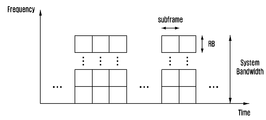
도 1은 LTE/LTE-A 시스템에서 시간 및 주파수 자원을 나타내는 도면이다. 1 is a diagram illustrating time and frequency resources in an LTE / LTE-A system.
도 1을 참조하면, 기지국(Evolved Node B : eNB)이 단말(User Equipment: UE)에게 전송하는 무선자원은 주파수축 상에서는 RB(resource block) 단위로 나누어지며 시간축 상에서는 서브 프레임(subframe) 단위로 나누어진다. Referring to FIG. 1, a radio resource transmitted from an evolved Node B (eNB) to a user equipment (UE) is divided into RBs (resource blocks) on the frequency axis and subframes Loses.
상기 RB는 LTE/LTE-A 시스템에서 일반적으로 12개의 부반송파(subcarrier)로 이루어지며 180kHz의 대역을 차지한다. 반면 서브 프레임(subframe)은 LTE/LTE-A 시스템에서 일반적으로 14개의 OFDM 심볼(symbol)구간으로 이루어지며 1 msec의 시간구간을 차지한다. LTE/LTE-A 시스템은 스케줄링을 수행함에 있어서 시간 축에서는 서브 프레임(subframe) 단위로 자원을 할당할 수 있으며 주파수축에서는 RB 단위로 자원을 할당할 수 있다.
The RB is generally composed of 12 subcarriers in the LTE / LTE-A system and occupies a band of 180 kHz. On the other hand, in a LTE / LTE-A system, a subframe generally consists of 14 OFDM symbols and occupies a time interval of 1 msec. In scheduling, the LTE / LTE-A system can allocate resources on a time axis in units of subframes and allocate resources in units of RBs on a frequency axis.
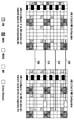
도 2는 LTE/LTE-A 시스템에서 하향링크로 스케줄링 할 수 있는 최소 단위인 1 subframe 및 1 RB의 무선자원을 나타내는 도면이다.2 is a diagram illustrating radio resources of 1 subframe and 1 RB, which are the minimum units that can be downlink-scheduled in the LTE / LTE-A system.
상기 도 2에 도시된 무선자원은 시간축 상에서 한 개의 서브 프레임(subframe)으로 이루어지며 주파수축 상에서 한 개의 RB로 이루어진다. 이와 같은 무선자원은 주파수 영역에서 12개의 부반송파로 이루어지며 시간영역에서 14개의 OFDM 심볼로 이루어져서 총 168개의 고유 주파수 및 시간 위치 갖도록 한다. LTE/LTE-A에서는 상기 도 2의 각각의 고유 주파수 및 시간 위치를 RE (resource element)라 한다.The radio resources shown in FIG. 2 are composed of one subframe on the time axis and one RB on the frequency axis. The radio resource is composed of 12 subcarriers in the frequency domain and 14 OFDM symbols in the time domain, thereby providing a total of 168 unique frequency and time positions. In LTE / LTE-A, the respective natural frequencies and time positions in FIG. 2 are referred to as RE (resource elements).
상기 도 2에 도시된 무선자원에는 다음과 같은 복수개의 서로 다른 종류의 신호가 전송될 수 있다.A plurality of different types of signals may be transmitted to the radio resource shown in FIG.
1. CRS (Cell Specific Reference Signal, 셀 특정 기준 신호): 한 개의 cell에 속한 모든 단말을 위하여 전송되는 기준신호One. CRS (Cell Specific Reference Signal): A reference signal transmitted for all terminals belonging to one cell
2. DMRS (Demodulation Reference Signal, 복조 기준 신호): 특정 단말을 위하여 전송되는 기준신호이며 PDSCH(Physical Downlink Shared Channel)에 실린 정보를 복원하기 위한 채널추정을 수행하는데 이용됨. 한 개의 DMRS port는 이와 연결된 PDSCH layer와 동일한 precoding이 적용되어 전송된다. PDSCH의 특정 layer를 수신하고자 하는 단말은 해당 layer와 연결된 DMRS port를 수신하여 채널 추정을 수행한 후 이를 이용하여 해당 layer에 실린 정보를 복원함.2. DMRS (Demodulation Reference Signal): This is a reference signal transmitted for a specific UE and is used to perform channel estimation to recover information contained in a PDSCH (Physical Downlink Shared Channel). One DMRS port is transmitted with the same precoding as the PDSCH layer connected thereto. A terminal desiring to receive a specific layer of the PDSCH receives the DMRS port connected to the layer, performs channel estimation, and restores information on the layer using the channel estimation.
3. PDSCH (Physical Downlink Shared Channel, 물리 하향 공용 채널): 하향링크로 전송되는 데이터 채널로 기지국이 단말에게 트래픽을 전송하기 위하여 이용하며 상기 도 2의 데이터 영역(data region)에서 기준 신호(Reference Signal)가 전송되지 않는 RE를 이용하여 전송됨3. PDSCH (Physical Downlink Shared Channel): A data channel transmitted in the downlink and used by a base station to transmit traffic to a mobile station. In the data region of FIG. 2, a reference signal Sent using a non-transmitted RE
4. CSI-RS (Channel Status Information Reference Signal, 채널 상태 정보 기준 신호): 한 개의 cell에 속한 단말들을 위하여 전송되는 기준신호이며, 채널상태를 측정하는데 이용됨. 한 개의 cell에는 복수개의 CSI-RS가 전송될 수 있음.4. CSI-RS (Channel Status Information Reference Signal): A reference signal transmitted for terminals belonging to one cell and used for measuring the channel status. A plurality of CSI-RSs can be transmitted to one cell.
5. ZP-CSI-RS (Zero Power CSI-RS): CSI-RS가 전송되는 위치에서 실제 신호가 전송되지 않는 것.5. ZP-CSI-RS: The actual signal is not transmitted at the position where the CSI-RS is transmitted.
6. IMR (Interference Measurement Resource): CSI-RS가 전송되는 위치에 해당하며 상기 도 2에서 A, B, C, D, E, F, G, H, I, J 중 하나 또는 복수를 IMR로 설정할 수 있음. 단말은 IMR로 설정된 RE들에서 수신되는 모든 신호를 간섭이라고 가정하고 간섭측정을 수행함.6. IMR (Interference Measurement Resource): It corresponds to the location where CSI-RS is transmitted, and one or more of A, B, C, D, E, F, G, H, . The UE assumes that all signals received in the REs set in the IMR are interference and perform interference measurement.
7.
기타 제어채널 (PHICH (Physical Hybrid-ARQ Indicator Channel), PCFICH(Physical Control Format Indicator Channel), PDCCH( Physical Downlink Control Channel)): 단말이 PDSCH를 수신하는데 필요한 제어정보를 제공하거나 상향링크의 데이터 송신에 대한 HARQ(Hybrid automatic repeat request)를 운용하기 위한 ACK/NACK 전송
7. Other Control Channels (PHICH, Physical Control Format Indicator Channel (PCFICH), Physical Downlink Control Channel (PDCCH)): Provides the control information necessary for the terminal to receive the PDSCH or uplink data ACK / NACK transmission for hybrid automatic repeat request (HARQ) transmission
상기 신호 외에 LTE-A 시스템에서는 서로 다른 기지국이 전송하는 CSI-RS가 해당 셀의 단말들에게 간섭 없이 수신될 수 있도록 zero power CSI-RS을 설정할 수 있다. 상기 zero power CSI-RS(muting)는 CSI-RS가 전송될 수 있는 위치에서 적용될 수 있으며 일반적으로 단말은 해당 무선 자원을 건너뛰어 트래픽 신호(traffic signal)를 수신한다. LTE-A 시스템에서 zero power CSI-RS(muting)는 또 다른 용어로 muting이라고 불리기도 한다. zero power CSI-RS(muting)의 특성상 CSI-RS의 위치에 적용되며 전송전력이 송신되지 않기 때문이다.In the LTE-A system in addition to the above-mentioned signal, zero power CSI-RS can be set so that CSI-RS transmitted by different base stations can be received without interference to the terminals of the corresponding cell. The zero power CSI-RS (muting) can be applied at a position where the CSI-RS can be transmitted. Generally, the UE receives a traffic signal by skipping the radio resource. In LTE-A systems, zero power CSI-RS (muting) is also referred to as muting in another term. zero power CSI-RS (muting) is applied to the location of the CSI-RS and the transmission power is not transmitted.
상기 도 2에서 CSI-RS는 CSI-RS를 전송하는 안테나들 수에 따라 A, B, C, D, E, E, F, G, H, I, J로 표시된 RE를 이용하여 전송될 수 있다. 또한 zero power CSI-RS(muting)도 A, B, C, D, E, E, F, G, H, I, J로 표시된 RE에 적용될 수 있다. 특히 CSI-RS는 전송하는 안테나포트 수에 따라서 2개, 4개, 8개의 RE로 전송될 수 있다. 안테나포트수가 2개일 경우 상기 도 2에서 특정 패턴(pattern)의 절반에 CSI-RS가 전송되며 안테나포트수가 4개일 경우 특정 패턴의 전체에 CSI-RS가 전송되고 안테나포트수가 8개일 경우 두 개의 패턴을 이용하여 CSI-RS가 전송된다. 반면 zero power CSI-RS(muting)의 경우 언제나 한 개의 패턴 단위로 전송이 이루어진다. 즉, zero power CSI-RS(muting)는 복수개의 패턴에 적용될 수는 있지만 CSI-RS와 위치가 겹치지 않는 경우에는 한 개의 패턴의 일부에만 적용되어 전송될 수는 없다. 단, CSI-RS의 위치와 zero power CSI-RS(muting)의 위치가 겹칠 경우에 한해서 한 개의 패턴의 일부에만 적용될 수 있다.2, the CSI-RS can be transmitted using REs denoted by A, B, C, D, E, E, F, G, H, I and J according to the number of antennas transmitting CSI- . The zero power CSI-RS (muting) can also be applied to REs labeled A, B, C, D, E, E, F, G, H, I, In particular, the CSI-RS can be transmitted in 2, 4, or 8 REs depending on the number of antenna ports to transmit. In the case where the number of antenna ports is two, the CSI-RS is transmitted in half of the specific pattern in FIG. 2. When the number of antenna ports is four, the CSI-RS is transmitted to all the specific patterns. The CSI-RS is transmitted. On the other hand, in the case of zero power CSI-RS (muting), transmission is always performed in one pattern unit. That is, the zero power CSI-RS (muting) can be applied to a plurality of patterns, but when the position does not overlap with the CSI-RS, it can not be applied to only a part of one pattern. However, it can be applied only to a part of one pattern only when the positions of the CSI-RS and the zero power CSI-RS (muting) are overlapped.
또한 상기 도 2의 A, B, C, D, E, F, G, H, I, J는 각각 IMR로 설정될 수도 있다. 특정 단말에게 IMR을 설정할 경우 해당 단말은 설정된 IMR에 속한 RE들에서 수신되는 신호를 간섭 신호(Interference Signal)라고 가정한다. IMR의 용도는 기지국이 단말로 하여금 간섭의 세기를 측정할 수 있도록 하는데 있다. 즉, 단말은 자신에게 설정된 IMR에 속한 RE들에서 수신되는 신호의 세기를 측정하여 간섭의 세기를 측정하는 것이다.2, A, B, C, D, E, F, G, H, I, and J may be set to IMR, respectively. When an IMR is set for a specific UE, the UE assumes that a signal received from the REs belonging to the set IMR is an interference signal. The purpose of the IMR is to allow the base station to measure the strength of the interference. That is, the UE measures the strength of a signal received from the REs belonging to the IMR set in the UE, and measures the strength of the interference.
도 3은 IMR의 동작원리를 설명하기 위하여 두 개의 기지국에서 전송되는 최소 단위의 무선자원을 나타내는 도면이다.도 3을 참조하면, 기지국 A는 cell A내에 위치하는 단말에 대하여 전송하는 무선자원의 RE에 IMR C를 설정한다. 또한 기지국 B는 cell B내에 위치하는 단말에 대하여 전송하는 무선자원의 RE에 IMR J를 설정한다. 3 is a diagram illustrating a minimum unit of radio resources transmitted from two base stations in order to explain the operation principle of the IMR. Referring to FIG. 3, a base station A transmits RE IMR C < / RTI > Further, the base station B sets IMR J to the RE of the radio resource to be transmitted to the terminal located in the cell B.
cell A내에 위치하는 단말들은 기지국 A에서 전송하는 PDSCH를 수신하게 되는데 이를 위하여 기지국 A로 채널 상태 정보를 통보해야 한다. 단말은 상기 채널상태 정보를 생성하기 위해서는 채널의 ( :잡음의 세기 :간섭의 세기 :신호 에너지) 를 측정할 수 있어야 한다. 상기 IMR은 단말이 간섭 및 잡음 세기를 측정할 수 있도록 하는데 그 목적이 있다. the UEs located in the cell A receive the PDSCH transmitted from the base station A and the channel state information must be notified to the base station A. [ In order to generate the channel state information, the UE must be able to measure the (: noise power: interference power: signal energy) of the channel. The IMR is intended to enable a terminal to measure interference and noise intensity.
상기 도 3에서는 기지국 A와 기지국 B가 동시에 전송할 경우 서로에게 간섭을 발생시킨다. 즉, 기지국 B에서 전송되는 신호는 기지국 A로부터 신호를 수신하고 있는 단말에게 간섭으로 작용한다. 또한 기지국 A에서 전송되는 신호는 기지국 B로부터 신호를 수신하고 있는 단말에게 간섭으로 작용한다.In FIG. 3, when the base station A and the base station B transmit at the same time, they generate interference with each other. That is, the signal transmitted from the base station B acts as an interference to the terminal receiving the signal from the base station A. Also, the signal transmitted from the base station A acts as interference to the terminal receiving the signal from the base station B.
상기 도 3에서 기지국 A는 cell A내에 위치한 단말이 기지국 B가 발생하는 간섭을 측정하도록 IMR C를 해당 단말에게 설정한다. 또한 기지국 A는 IMR C의 위치에서 신호를 전송하지 않는다. 결과적으로 단말이 IMR C에서 수신하는 신호는 기지국 B에서 전송한 신호이다. (300, 310) 즉, 단말은 IMR C에서 기지국 B에서 전송한 신호만을 수신하게 되며 이 신호에 대한 수신세기를 측정하여 기지국 B에서 발생하는 간섭의 세기를 판단할 수 있게 된다. 마찬가지로 기지국 B는 cell B내에 위치한 단말이 기지국 A가 발생하는 간섭을 측정하도록 IMR J를 해당 단말에게 설정한다. 또한 기지국 B는 IMR J의 위치에서 신호를 전송하지 않는다. 결과적으로 단말이 IMR J에서 수신하는 신호는 기지국 A에서 전송한 신호이다. (320, 330)In FIG. 3, the base station A sets the IMR C to the corresponding terminal so that the terminal located in the cell A measures the interference generated by the base station B. Also, base station A does not transmit signals at the location of IMR C. As a result, the signal received by the terminal in the IMR C is the signal transmitted from the base station B. That is, the UE receives only the signal transmitted from the base station B in the IMR C, and measures the reception strength of the signal to determine the strength of the interference generated in the base station B. Similarly, the base station B sets the IMR J to the corresponding terminal so that the terminal located in the cell B measures the interference generated by the base station A. Also, base station B does not transmit signals at the location of IMR J. As a result, the signal received by the terminal at the IMR J is the signal transmitted from the base station A. (320, 330)
상기 도 3과 같이 IMR을 이용할 경우 다른 기지국 또는 전송지점에서 발생되는 간섭의 세기를 효과적으로 측정할 수 있다. 즉 복수의 셀이 공존하는 다중 셀 이동통신 시스템(Multi Cell Wireless System) 또는 분산 안테나 시스템(Distributed antenna system)에서 상기 IMR을 활용하여 인접 셀에서 발생되는 간섭의 세기 또는 인접 전송지점에서 발생되는 간섭의 세기를 효과적으로 측정할 수 있다. 반면 이와 같은 IMR이 효과적으로 측정할 수 없는 간섭은 MU-MIMO(Multi User - Multiple Input Multiple Output) 간섭의 세기이다. As shown in FIG. 3, when the IMR is used, it is possible to effectively measure the strength of interference generated at other base stations or transmission points. That is, in a multi-cell mobile communication system or a distributed antenna system in which a plurality of cells coexist, the strength of interference generated in a neighboring cell or the interference generated in a neighboring transmission point The strength can be measured effectively. On the other hand, interference that can not be effectively measured by such an IMR is the strength of MU-MIMO (Multi User-Multiple Input Multiple Output) interference.
LTE 시스템에서는 복수의 송수신 안테나를 활용하여 MIMO (Multiple Input Multiple Output) 전송을 지원한다. MIMO 전송은 복수개의 송수신 안테나에서 발생되는 순간적인 채널에 맞추어 공간적으로 정보를 다중화하여 전송하는 것이다. MIMO 전송은 한 개의 시간 및 주파수 자원에 복수의 데이터 스트림(data stream)를 공간적으로 다중화하여 보낼 수 있기 때문에 데이터 전송률을 기존의 non-MIMO 전송과 비교하여 몇 배 증가시킬 수 있다. LTE Release 11에서는 최대 8개의 송신안테나와 최대 8개의 수신안테나 사이에서 이루어지는 MIMO 전송을 지원한다. 이와 같은 경우 최대 8개의 data stream을 공간적으로 다중화하여 보낼 수 있게 되며 최대 데이터 전송률을 non-MIMO와 비교하여 8배로 높일 수 있다.The LTE system supports multiple input multiple output (MIMO) transmission using multiple transmit and receive antennas. In the MIMO transmission, information is multiplexed spatially in accordance with an instantaneous channel generated in a plurality of transmission / reception antennas. Since the MIMO transmission can spatially multiplex and transmit a plurality of data streams to one time and frequency resource, the data transmission rate can be increased several times as compared with the existing non-MIMO transmission. LTE Release 11 supports MIMO transmission between up to 8 transmit antennas and up to 8 receive antennas. In this case, up to 8 data streams can be spatially multiplexed and transmitted, and the maximum data rate can be increased by 8 times compared with non-MIMO.
일반적으로 MIMO 전송은 한 개의 단말에게 공간적으로 다중화된 복수개의 data stream을 전송하는 SU-MIMO(Single User - Multiple Input Multiple Output)전송과 복수의 단말에게 동시에 공간적으로 다중화된 복수개의 data stream을 전송하는 MU-MIMO(Multi User - Multiple Input Multiple Output )전송으로 구분된다. SU-MIMO의 동작에서는 공간적으로 다중화된 복수개의 data stream이 한 개의 단말에게 전송되지만 MU-MIMO의 동작에서는 공간적으로 다중화된 복수개의 data stream이 복수의 단말에게 전송된다. MU-MIMO의 동작에서 기지국은 복수의 data stream을 전송하며 각 단말은 기지국이 전송한 복수의 data stream 중 하나 이상의 data stream을 수신하게 된다. 이와 같은 MU-MIMO의 동작은 기지국의 송신안테나가 단말의 수신안테나보다 많을 경우 특히 유용하다. SU-MIMO 전송의 경우 공간적으로 다중화할 수 있는 data stream의 최대 개수가 min(NTx(기지국의 송신안테나 수), NRx(단말의 수신 안테나 수))에 의하여 제한된다. 반면 MU-MIMO의 경우 공간적으로 다중화할 수 있는 data stream의 최대 개수가 min(NTx, NMS(단말의 개수)*NRx)에 의하여 제한된다. 상기 도 3에서 IMR이 다른 eNB 또는 전송지점에서 발생되는 간섭의 세기를 효과적으로 측정할 수 있는 반면 효과적으로 측정할 수 없는 것은 동일한 eNB 또는 전송 지점 내에서 발생하는 MU-MIMO 간섭의 세기이다.In general, a MIMO transmission transmits a single user-multiple input multiple output (SU-MIMO) transmission, which transmits a plurality of data streams spatially multiplexed to one terminal, and a plurality of data streams simultaneously spatially multiplexed to a plurality of terminals And MU-MIMO (Multi User-Multiple Input Multiple Output) transmission. In the operation of SU-MIMO, a plurality of spatially multiplexed data streams are transmitted to one terminal, but in the operation of MU-MIMO, a plurality of spatially multiplexed data streams are transmitted to a plurality of terminals. In the MU-MIMO operation, the base station transmits a plurality of data streams, and each terminal receives one or more data streams of a plurality of data streams transmitted by the base station. The operation of the MU-MIMO is particularly useful when the transmission antenna of the base station is larger than the reception antenna of the terminal. In the case of SU-MIMO transmission, the maximum number of data streams that can be multiplexed spatially is limited by min (NTx (number of transmit antennas of the base station) and NRx (number of receive antennas of the terminal)). On the other hand, in the case of MU-MIMO, the maximum number of data streams that can be multiplexed spatially is limited by min (NTx, NMS (number of terminals) * NRx). In FIG. 3, the IMR can effectively measure the strength of interference generated at another eNB or transmission point, while it can not effectively measure the strength of MU-MIMO interference occurring in the same eNB or transmission point.
일반적으로 다중셀 이동통신 시스템에서 단말이 수신하는 신호는 다음과 같은 수학식으로 표현할 수 있다.Generally, a signal received by a UE in a multi-cell mobile communication system can be expressed by the following equation.
<수학식1>&Quot; (1) "

상기 수학식에서 ![]()
![]()
![]()
![]()
![]()
![]()
![]()
![]()
![]()
![]()
![]()
![]()
<수학식2>&Quot; (2) "

상기 수학식 2에서 0번째 eNB가 0번째 단말에게 전송한 신호 성분은 


MU-MIMO interference를 IMR을 이용하여 측정할 수 없는 이유는 MU-MIMO interference를 발생시키는 eNB에서 IMR에 신호를 전송하지 않기 때문이다. 즉, 상기 도 3에서 IMR의 구동 원리상 eNB A는 MU-MIMO의 동작으로 복수개의 단말에게 신호를 전송하는 경우에 IMR C에 신호를 전송하지 않는다. 이 경우 eNB A의 하향링크에 대한 채널 상태 정보를 결정하는 단말은 IMR C에서 eNB B가 발생시키는 간섭은 효과적으로 측정할 수 있지만 eNB A에서 발생되는 MU-MIMO interference는 측정할 수 없게 된다.MU-MIMO interference can not be measured using IMR because the eNB that generates MU-MIMO interference does not transmit the signal to the IMR. That is, in the operation principle of the IMR in FIG. 3, the eNB A does not transmit a signal to the IMR C when a signal is transmitted to a plurality of terminals by the operation of the MU-MIMO. In this case, the UE determining the channel status information for the downlink of the eNB A can effectively measure the interference generated by the eNB B in IMR C, but can not measure the MU-MIMO interference generated in the eNB A.
단말이 채널상태 정보를 결정함에 있어서 MU-MIMO interference를 정확하게 측정하지 못 하는 상황에 기지국이 MU-MIMO 전송을 해당 단말을 포함한 복수의 단말에게 송신할 때 최적화되지 못한 시스템 성능을 얻게 된다. 최적화되지 못한 시스템 성능을 얻는 이유는 기지국이 효과적으로 링크 적응 (link adaptation)을 수행하지 못하기 때문이다. 상기 link adaptation이라 함은 단말의 채널상태에 맞는 data rate를 할당하는 것을 의미하는데 LTE와 같은 이동통신 시스템에서는 이를 단말이 전송한 채널상태 정보를 근거로 수행한다. 문제는 단말이 MU-MIMO interference를 측정하지 못함에 따라 기지국에 통보하는 채널상태 정보가 MU-MIMO의 동작으로 전송하는 경우에 적합하지 않게 되며 따라서 효과적인 link adaptation이 이루어지기 힘들다는 점이다.In a situation where the UE can not accurately measure the MU-MIMO interference in determining the channel state information, when the base station transmits the MU-MIMO transmission to a plurality of UEs including the UE, the system performance is not optimized. The reason for getting unoptimized system performance is that the base station can not effectively perform link adaptation. The link adaptation refers to allocating a data rate according to the channel state of the UE. In a mobile communication system such as LTE, the link adaptation is performed based on channel state information transmitted from the UE. The problem is that when the UE fails to measure MU-MIMO interference, channel state information notified to the base station is not suitable for transmission in the MU-MIMO operation, and thus it is difficult to effectively perform link adaptation.
상기와 같이 채널상태 정보에 MU-MIMO interference의 영향을 반영하지 못하여 성능 저하가 특히 심하게 발생하는 경우는 Massive MIMO 또는 Full Dimension MIMO (FD-MIMO)와 같이 다수의 단말에게 동시에 MU-MIMO 전송을 수행하는 이동통신 시스템에서다.If the performance degradation occurs particularly because the influence of MU-MIMO interference is not reflected in the channel state information, MU-MIMO transmission is simultaneously performed to a plurality of UEs such as Massive MIMO or Full-Dimension MIMO (FD-MIMO) In the mobile communication system.
Massive MIMO 또는 Full Dimension MIMO는 기지국에서의 송신안테나 개수가 수십에서 수백 개에 달한다. 또한 시스템 성능 향상을 위하여 다중화할 수 있는 data stream의 개수를 종래 LTE 시스템과 비교하여 대폭 증가시켜야 한다. 이와 같은 목적으로 FD-MIMO를 지원하는 이동통신 시스템은 MU-MIMO 전송을 활용하여 동시에 다수의 단말에게 동시전송을 수행할 수 있어야 한다.
Massive MIMO or Full-Dimension MIMO has tens to hundreds of transmit antennas at the base station. In order to improve the system performance, the number of data streams that can be multiplexed must be significantly increased compared with the conventional LTE system. For this purpose, a mobile communication system supporting FD-MIMO should be capable of simultaneously transmitting to multiple terminals simultaneously using MU-MIMO transmission.
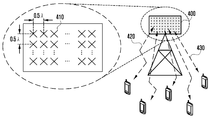
도 4는 FD-MIMO 전송을 지원하는 기지국을 나타내는 도면이다.4 is a diagram illustrating a base station supporting FD-MIMO transmission.
도 4를 참조하면, 기지국은 다수의 송신안테나의 집합(400)로 구성될 수 있으며, 각 송신안테나(410)를 통하여 복수의 단말에게 신호를 동시에 송신할 수 있다(420, 430).Referring to FIG. 4, a base station may include a plurality of sets of transmit
상기 도 4에서 다수의 송신안테나는 한 예로 2차원적인 평면 구조를 갖는 안테나 패널 (2-D antenna array panel)로 구성될 수 있으며 각 안테나는 410과 같이 다른 안테나들과 파장의 길이의 함수에 해당하는 거리를 가지며 배치된다. 상기 다수의 안테나 집합에 해당하는 400을 이용하여 기지국은 복수의 단말에게 high order MU-MIMO (고차원 다중사용자 MIMO)를 이용하여 송신한다. High order MU-MIMO 전송이라 함은 다수의 기지국 송신안테나를 이용하여 다수의 단말에게 공간적으로 분리된 송신빔을 할당하여 데이터를 송신하는 것이다. High order MU-MIMO는 동일한 시간 및 주파수 자원을 이용하여 이루어지기 때문에 시스템의 성능을 대폭 개선시킬 수 있는 장점이 있다.
In FIG. 4, the plurality of transmit antennas may be a 2-D antenna array panel having a two-dimensional plane structure, and each antenna may correspond to a function of the length of the wavelength with other antennas, As shown in FIG. The base station transmits high order MU-MIMO (high dimensional multi-user MIMO) to a plurality of terminals using the 400 corresponding to the plurality of antenna sets. High order MU-MIMO transmission refers to transmission of data by allocating a spatially separated transmission beam to a plurality of terminals using a plurality of base station transmission antennas. Since the high order MU-MIMO is performed using the same time and frequency resources, there is an advantage that the performance of the system can be greatly improved.
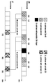
도 5는 종래 기술에 따라 eNB가 전송하는 하향링크와 이를 수신한 단말이 다시 채널상태 정보를 전송하는 상향링크를 시간영역에서 나타내는 도면이다.5 is a diagram illustrating a downlink transmitted by an eNB according to a conventional technique and an uplink through which a terminal receiving the uplink transmits channel state information again in a time domain.
도 5를 참조하면, eNB가 전송하는 하향링크는 IMR를 전송하는 subframe(500, 520, 550)과 CSI-RS를 전송하는 subframe(510, 530, 560)과 aperiodic CSI trigger를 전송하는 subframe(540)을 포함할 수 있으며, UE가 전송하는 상향링크는 periodic CSI를 전송하는 subframe(570, 580)과 aperiodic CSI를 전송하는 subframe(590)을 포함할 수 있다.5, the downlink transmitted by the eNB includes
도 5에서 eNB는 서브프레임(subframe) 500, 520, 550에서 IMR이 주기적으로 위치하도록 설정한다. 즉, eNB는 단말에게 해당 subframe의 특정 IMR 위치에서 간섭을 측정하도록 상위 시그널링(Signaling)을 이용하여 통보하는 것이다. 이를 통보 받은 단말은 해당 IMR에서 간섭을 측정하여 채널 상태 정보를 생성한다. 또한 eNB는 subframe 510, 530, 560에서 CSI-RS를 전송하며 이를 단말에게 상위 시그널링을 이용하여 통보한다. 이를 통보 받은 단말은 해당 subframe에서 CSI-RS를 수신하여 채널 상태 정보를 생성한다. 일반적으로 채널상태 정보를 생성하기 위해서는 
LTE Release 11에서 비주기적 피드백 지시자는 상향링크 DCI format 0 또는 DCI format 4에 포함되며 한 비트 또는 두 비트로 정의된다. 피드백 지시자가 한 비트인 경우에 이 비주기적 피드백 지시자가 ON으로 설정되면 단말은 'serving cell c'에 대한 채널 정보를 PUSCH 비주기적 피드백으로 기지국에 전달한다. 여기서 serving cell c의 의미는 carrier aggregation(CA) 상황에서 DCI가 전송되는 하향링크 component carrier(CC)를 의미한다. 반면에 비주기적 피드백 지시자가 두 비트인 경우에 단말은 하기 표 1-1과 1-2에서 정의된 방법으로 비주기적 피드백을 수행한다.
In LTE Release 11, the aperiodic feedback indicator is included in the
표 1-1 전송 모드 (Transmission Mode) 10 에서의 두 비트 비주기적 피드백 지시자(CSI Request Field)에 대한 비주기적 피드백 수행 방법Table 1-1 Methods of Non-Periodic Feedback on CSI Request Field with Two-Bit Non-Periodic Feedback Indicator in Transmission Mode 10

표 1-2 전송 모드 (Transmission Mode) 1-9 에서의 두 비트 비주기적 피드백 지시자(CSI Request Field)에 대한 비주기적 피드백 수행 방법Table 1-2 Transmission Mode (Transmission Mode) How to Perform Nonperiodic Feedback on Two Bit Non-Periodic Feedback Indicator (CSI Request Field) in 1-9

표 1-1 과 1-2 에서 'serving cell c'의 의미는 비주기적 피드백 지시자가 한 비트인 경우와 달리 상향링크 스케줄링(Uplink Scheduling)을 위한 DCI에 포함되는 CIF (carrier indication field)가 지시하는 상향링크 CC에 링크된 하향링크 CC를 의미한다. 즉 단말이 '01'로 설정된 비주기적 피드백 지시자를 수신하면 단말은 CIF가 지시하는 상향링크 CC에서 이와 링크된 하향링크 CC의 피드백 정보를 전송할 수 있다. 반면에 단말이 '10' 또는 '11'로 설정된 비주기적 피드백 지시자를 수신하면 단말은 CIF가 지시하는 상향링크 CC에 대하여 상위로 설정된 하향링크 CC에 대한 피드백 정보를 전송하게 된다.The meaning of 'serving cell c' in Tables 1-1 and 1-2 is that the CIF (carrier indication field) included in the DCI for uplink scheduling is different from the case where the non-periodic feedback indicator is one bit Means a downlink CC linked to an uplink CC. That is, when the UE receives the aperiodic feedback indicator set to '01', the UE can transmit the feedback information of the DL CC linked thereto in the UL CC indicated by the CIF. On the other hand, if the UE receives the aperiodic feedback indicator set to '10' or '11', the UE transmits feedback information on the uplink CC set up to the uplink CC indicated by the CIF.
상기 도 5에서 단말이 570, 580에서 기지국에 보고하는 채널상태 정보는 periodic 채널상태 정보에 해당된다. 단말은 570, 580의 채널상태 정보를 생성하는데 있어서 CSI-RS와 IMR에서 신호에너지와 잡음 및 간섭의 세기를 각각 측정한다. 마찬가지로 590의 aperiodic 채널상태 정보를 생성하는 경우에도 CSI-RS와 IMR에서 신호에너지와 잡음 및 간섭의 세기를 각각 측정한다. 종래 기술을 적용할 경우 periodic 채널상태 정보와 aperiodic 채널상태 정보에서 MU-MIMO interference를 측정하지 못함에 따라 FD-MIMO 시스템과 같이 high order MU-MIMO를 운용하는 경우 시스템 성능 저하를 초래할 수 있다.In FIG. 5, the channel state information reported from the UE to the BS in
MU-MIMO interference는 eNB에서 어떤 복수 단말의 조합에게 MU-MIMO 전송을 수행하느냐 여부에 따라 그 크기 및 특성이 달라질 수 있다.
MU-MIMO interference may vary in size and characteristics depending on whether MU-MIMO transmission is performed on a combination of a plurality of terminals in the eNB.
도 6은 subframe 별로 기지국에서 MU-MIMO 전송을 수행하는 것을 나타내는 도면이다.6 is a diagram illustrating an MU-MIMO transmission performed by a base station for each subframe.
상기 도 6을 참조하면, eNB가 수행하는 MU-MIMO 전송은 k subframe에서 ![]()
![]()
![]()
![]()
![]()
![]()
도 6에서 eNB는 subframe별로 다른 단말의 조합에 대하여 MU-MIMO 전송을 수행하고 있음을 알 수 있다. 한 예로 subframe 0에서 eNB i는 ![]()
![]()
![]()
In FIG. 6, it can be seen that the eNB performs MU-MIMO transmission for different combinations of terminals for each subframe. For example, in ![]()
![]()
![]()
도 7은 eNB이 subframe에서 복수의 단말에게 MU-MIMO 전송을 수행했을 때 한 개의 단말이 받는 MU-MIMO 간섭을 나타내는 도면이다.7 is a diagram illustrating MU-MIMO interference received by one UE when an eNB performs MU-MIMO transmission to a plurality of UEs in a subframe.
도 7을 참조하면, 단말 A,B,C,D는 eNB가 전송한 PDSCH신호가 precoding을 거친 후 무선 채널을 통과한 결과를 수신한다. (700, 701, 702, 703) Referring to FIG. 7, terminals A, B, C, and D receive a result of precoding through a PDSCH signal transmitted by an eNB and passing through a wireless channel. (700, 701, 702, 703)
단말 A는 700과 같이 eNB가 전송한 신호를 수신한다. 상기 도 7에서 ![]()
![]()
![]()
![]()
![]()
![]()
![]()
![]()
FD-MIMO와 같이 high order MU-MIMO가 적용되는 경우 고려해야 할 또 한가지 사항은 동시에 스케쥴링(scheduling)되는 단말의 개수이다. 즉, eNB가 MU-MIMO 전송을 수행할 때 그 대상이 되는 단말은 매 subframe마다 다른 조합의 단말들일 수 있을 뿐만 아니라 그 개수도 다를 수 있다. 즉, 상기 도 6에서 subframe 600에서 eNB가 MU-MIMO 신호를 전송하는 단말의 수는 subframe 610에서 eNB가 MU-MIMO 신호를 전송하는 단말의 수와 다를 수 있다.When high order MU-MIMO such as FD-MIMO is applied, another thing to consider is the number of UEs that are scheduled at the same time. That is, when the eNB performs MU-MIMO transmission, the target terminal may be a different combination terminal for each subframe, and the number of terminals may be different. That is, the number of UEs to which the eNB transmits an MU-MIMO signal in the
일반적으로 eNB는 제한된 송신전력을 이용하여 하향링크 전송을 수행한다. 즉, eNB의 최대송신전력이 ![]()
![]()
In general, an eNB performs downlink transmission using limited transmission power. That is, the maximum transmission power of the eNB ![]()
![]()
도 8은 eNB가 MU-MIMO의 동작으로 신호를 송신할 때 각 단말에게 할당하는 송신전력과 단말이 채널상태 정보를 생성하기 위하여 측정하는 CSI-RS의 송신전력을 나타내는 도면이다. 8 is a diagram showing transmission power allocated to each UE when the eNB transmits a signal in the MU-MIMO operation and transmission power of the CSI-RS measured by the UE to generate channel status information.
도 8에서 단말에게 송신되는 PDSCH는 MU-MIMO의 동작을 이용하여 전송된다. 때문에 eNB의 송신전력이 복수개의 단말들 사이에 배분되어야 한다. 반면 단말이 채널상태정보를 생성하기 위하여 측정하는 CSI-RS는 eNB의 송신전력을 다른 단말과 나눌 필요가 없다. 상기 도 8에서 단말이 PDSCH에 할당된 송신전력이 CSI-RS에 할당된 송신전력의 1/4이라는 것을 모르는 상태에서 채널상태정보를 생성하는 경우 부정확한 채널상태정보를 기지국에 보고하게 되며 결과적으로 MU-MIMO 전송의 성능을 하락시키게 된다.The PDSCH transmitted to the UE in FIG. 8 is transmitted using the operation of the MU-MIMO. Therefore, the transmission power of the eNB must be distributed among a plurality of terminals. On the other hand, the CSI-RS that the UE measures to generate channel state information does not need to divide the transmission power of the eNB with other UEs. In FIG. 8, when the UE generates channel state information in a state where it does not know that the transmission power allocated to the PDSCH is 1/4 of the transmission power allocated to the CSI-RS, the UE reports incorrect channel state information to the base station. The performance of the MU-MIMO transmission is degraded.
상기 도 4와 같은 FD-MIMO 시스템의 성능이 최적화되기 위해서는 단말이 eNB에 보고하는 채널상태 정보가 다른 eNB가 발생하는 MU-MIMO 간섭(interference)뿐만 아니라 자신을 위한 PDSCH를 송신하는 eNB에서 발생되는 MU-MIMO 간섭도 고려해야 한다. 이를 위해서는 단말이 채널상태 정보를 생성하는 과정에서 MU-MIMO 간섭을 정확하게 측정하는 방법이 필요하다. 또한 단말은 채널상태 정보를 생성하는 과정에서 eNB가 전송하는 전력 중 자신에게 할당된 전송전력이 얼마인지를 사전에 파악하고 있어야 한다.In order to optimize the performance of the FD-MIMO system as shown in FIG. 4, the channel state information reported by the UE to the eNB is generated not only by the MU-MIMO interference generated by another eNB, but also by the eNB transmitting the PDSCH for itself MU-MIMO interference must also be considered. For this, a method for accurately measuring MU-MIMO interference in the process of generating channel state information is required. In addition, the UE must know in advance how much of the power transmitted by the eNB is allocated to the UE in the process of generating channel state information.
본 명세서의 실시 예는 상술한 문제점을 해결하기 위하여 제안된 것으로 이와 같은 이동 통신 시스템에서 단말이 단말의 서빙 기지국이 다중 사용자 장치에게 전송한 신호로 인해 발생한 간섭을 측정하여 이를 채널상태 정보에 반영하는 방법 및 장치를 제공하고자 한다.Embodiments of the present invention have been proposed in order to solve the above-described problems. In the mobile communication system, a UE measures interference generated due to a signal transmitted from a serving base station of a UE to a multi-user device, Method, and apparatus.
상술한 과제를 달성하기 위하여, 본 명세서의 일 실시 예에 따르는 이동통신시스템에서 기지국이 단말의 채널 상태 정보 보고 시 에 간섭을 측정하게 하는 방법 은, 단말의 서빙 기지국이 다중 사용자 장치에게 전송한 신호로 인해 발생한 간섭을 측정하기 위한 정보를 설정하는 단계; 상기 설정한 정보를 단말에 전달하는 단계; 및 상기 정보를 기반으로 측정된 간섭을 이용하여 생성된 채널상태 정보를 단말로부터 수신하는 단계 를 포함하는 것을 특징으로 한다.According to an aspect of the present invention, there is provided a method of measuring interference in a mobile communication system in reporting a channel state information of a mobile station in a mobile communication system, the method comprising: The method comprising: setting information for measuring an interference caused by the interference; Transmitting the set information to a terminal; And receiving channel state information generated using the interference measured based on the information, from the terminal.
본 명세서의 다른 실시 예에 따른 이동통신시스템에서 단말의 채널 상태 정보 보고 시에 간섭을 측정하는 방법은, 단말의 서빙 기지국이 다중 사용자 장치에게 전송한 신호로 인해 발생한 간섭을 측정하기 위한 정보를 기지국으로부터 수신하는 단계; 상기 정보를 기반으로 간섭을 측정하는 단계; 상기 측정된 간섭을 이용하여 채널상태 정보를 생성하는 단계; 및 상기 생성한 채널상태 정보를 기지국으로 전달하는 단계를 포함하는 것을 특징으로 한다.A method for measuring interference at the time of reporting channel state information of a mobile station in a mobile communication system according to another embodiment of the present invention includes the steps of measuring interference generated due to a signal transmitted from a serving base station ; Measuring interference based on the information; Generating channel state information using the measured interference; And transmitting the generated channel state information to a base station.
본 명세서의 다른 실시 예에 따른 이동통신시스템에서 단말의 채널 상태 정보 보고 시에 간섭을 측정하게 하는 기지국은 단말과 신호를 송수신하는 송수신부; 및 단말의 서빙 기지국이 다중 사용자 장치에게 전송한 신호로 인해 발생한 간섭을 측정하기 위한 정보를 설정하고, 상기 설정한 정보를 단말에 전달하고, 상기 정보를 기반으로 측정된 간섭을 이용하여 생성된 채널상태 정보를 단말로부터 수신하는 것을 제어하는 제어부를 포함하는 것을 특징으로 한다.In a mobile communication system according to another embodiment of the present invention, a base station for measuring interference in reporting channel state information of a terminal includes a transmitting and receiving unit transmitting and receiving signals to and from a terminal; And setting information for measuring interference caused by a signal transmitted from the serving base station of the mobile subscriber station to the multi user equipment, transmitting the set information to the mobile subscriber station, generating a channel using the interference measured based on the information, And a control unit for controlling reception of the status information from the terminal.
본 명세서의 다른 실시 예에 따른 이동통신시스템에서 채널 상태 정보 보고 시에 간섭을 측정하는 단말은, 기지국과 신호를 송수신하는 송수신부; 및 단말의 서빙 기지국이 다중 사용자 장치에게 전송한 신호로 인해 발생한 간섭을 측정하기 위한 정보를 기지국으로부터 수신하고, 상기 정보를 기반으로 간섭을 측정하고, 상기 측정된 간섭을 이용하여 채널상태 정보를 생성하고, 상기 생성한 채널상태 정보를 기지국으로 전달하는 것을 제어하는 제어부를 포함하는 것을 특징으로 한다.
In a mobile communication system according to another embodiment of the present invention, a terminal for measuring interference at the time of channel state information reporting includes a transmitter / receiver for transmitting / receiving signals to / from a base station; And receiving information for measuring interference caused by a signal transmitted from the serving base station of the mobile station to the multi-user device from a base station, measuring interference based on the information, and generating channel state information using the measured interference And transmitting the generated channel state information to the base station.
본 명세서의 실시 예에 따르면 이동 통신 시스템에서 단말이 다중 사용자 기반의 멀티 입출력 시스템(MU-MIMO)에서 단말이 다른 eNB가 발생하는 MU-MIMO 간섭뿐만 아니라 자신을 위한 PDSCH를 송신하는 eNB에서 발생되는 MU-MIMO의 간섭도 고려하여 이를 채널 상태 정보에 반영할 수 있게 된다. 이러한 단말의 반영 기술에 따라 단말의 채널 상태에 맞는 data rate를 할당(link adaptation)하게 되어 최적화된 시스템 성능을 얻을 수 있다.According to the embodiment of the present invention, in a mobile communication system, in a multi-user multi-input / multi-output system (MU-MIMO), a UE generates not only MU-MIMO interference generated by another eNB but also an eNB The interference of the MU-MIMO can be considered and reflected in the channel state information. According to the reflection technique of such a terminal, a data rate matching a channel state of the terminal is allocated (link adaptation), and optimized system performance can be obtained.
도 1은 LTE/LTE-A 시스템에서 시간 및 주파수 자원을 나타내는 도면이다.
도 2는 LTE/LTE-A 시스템에서 하향링크로 스케줄링 할 수 있는 최소 단위인 1 subframe 및 1 RB의 무선자원을 나타내는 도면이다.
도 3은 IMR의 동작원리를 설명하기 위하여 두 개의 기지국에서 전송되는 최소 단위의 무선자원을 나타내는 도면이다.
도 4는 FD-MIMO 전송을 지원하는 기지국을 나타내는 도면이다.
도 5는 종래 기술에 따라 eNB가 전송하는 하향링크와 이를 수신한 단말이 다시 채널상태 정보를 전송하는 상향링크를 시간영역에서 나타내는 도면이다.
도 6은 subframe 별로 기지국에서 MU-MIMO 전송을 수행하는 것을 나타내는 도면이다.
도 7은 eNB이 subframe에서 복수의 단말에게 MU-MIMO 전송을 수행했을 때 한 개의 단말이 받는 MU-MIMO 간섭을 나타내는 도면이다.
도 8은 eNB가 MU-MIMO의 동작으로 신호를 송신할 때 각 단말에게 할당하는 송신전력과 단말이 채널 상태 정보를 생성하기 위하여 측정하는 CSI-RS의 송신전력을 나타내는 도면이다.
도 9는 본 발명의 실시 예에 따라 기지국이 단말에게 단말의 서빙 기지국이 다중 사용자 장치에게 전송한 신호로 인해 발생한 간섭을 측정하게 하기 위하여 하나의 CSI-Process에 해당하는 IMR을 할당하는 방법을 나타내는 도면이다.
도 10은 본 발명의 또 다른 실시 예에 따라 기지국이 단말에게 단말의 서빙 기지국이 다중 사용자 장치에게 전송한 신호로 인해 발생한 간섭을 측정하게 하기 위하여 하나의 CSI-Process에 해당하는 IMR을 할당하는 방법을 나타내는 도면이다.
도 11은 본 발명의 또 다른 실시 예에 따라 기지국이 단말에게 단말의 서빙 기지국이 다중 사용자 장치에게 전송한 신호로 인해 발생한 간섭을 측정하게 하기 위하여 하나의 CSI-Process에 해당하는 IMR을 할당하는 방법을 나타내는 도면이다.
도 12는 본 발명의 또 다른 실시 예에 따라 채널 상태 정보 보고를 하는 방법과 그 예시를 나타내는 도면이다.
도 13은 본 발명의 또 다른 실시 예에 따라 기지국이 단말에게 단말의 서빙 기지국이 다중 사용자 장치에게 전송한 신호로 인해 발생한 간섭을 측정하게 하기 위하여 하나의 CSI-Process에 해당하는 IMR을 할당하는 방법을 나타내는 도면이다.
도 14은 본 발명의 또 다른 실시 예에 따라 기지국이 단말에게 단말의 서빙 기지국이 다중 사용자 장치에게 전송한 신호로 인해 발생한 간섭을 측정하게 하기 위하여 하나의 CSI-Process에 해당하는 IMR을 할당하는 방법을 나타내는 도면이다.
도 15는 본 발명의 또 다른 실시 예에 따라 기지국이 단말에게 단말의 서빙 기지국이 다중 사용자 장치에게 전송한 신호로 인해 발생한 간섭을 측정하게 하기 위하여 하나의 CSI-Process에 해당하는 IMR을 할당하는 방법을 나타내는 도면이다.
도 16은 본 발명의 또 다른 실시 예에 따라 기지국이 단말에게 단말의 서빙 기지국이 다중 사용자 장치에게 전송한 신호로 인해 발생한 간섭을 측정하게 하기 위하여 하나의 CSI-Process에 해당하는 IMR을 할당하는 방법을 나타내는 도면이다.
도 17은 본 발명에 따라 단말에게 MU-CSI report를 지시하는 기지국의 동작을 설명한 도면이다.
도 18은 본 발명에 따라 기지국에게 MU-CSI report 하는 단말의 동작을 설명한 도면이다.
도 19는 본 발명에 따라 기지국 내부 구조를 도시하는 블록도이다.
도 20은 본 발명에 따라 단말의 내부 구조를 도시하는 블록도이다.1 is a diagram illustrating time and frequency resources in an LTE / LTE-A system.
2 is a diagram illustrating radio resources of 1 subframe and 1 RB, which are the minimum units that can be downlink-scheduled in the LTE / LTE-A system.
3 is a diagram illustrating a minimum unit of radio resources transmitted from two base stations in order to explain the operation principle of the IMR.
4 is a diagram illustrating a base station supporting FD-MIMO transmission.
5 is a diagram illustrating a downlink transmitted by an eNB according to a conventional technique and an uplink through which a terminal receiving the uplink transmits channel state information again in a time domain.
6 is a diagram illustrating an MU-MIMO transmission performed by a base station for each subframe.
7 is a diagram illustrating MU-MIMO interference received by one UE when an eNB performs MU-MIMO transmission to a plurality of UEs in a subframe.
8 is a diagram showing transmission power allocated to each UE when the eNB transmits a signal in the MU-MIMO operation and transmission power of the CSI-RS measured by the UE to generate channel status information.
9 illustrates a method of allocating an IMR corresponding to one CSI-Process in order to measure interference generated due to a signal transmitted from a serving base station of a UE to a multi-user device by a base station according to an embodiment of the present invention FIG.
10 is a diagram illustrating a method of allocating an IMR corresponding to one CSI-Process in order to allow a base station to measure an interference caused by a signal transmitted from a serving base station of a UE to a multi-user device according to another embodiment of the present invention Fig.
11 is a diagram illustrating a method of allocating an IMR corresponding to one CSI-Process in order to measure an interference caused by a signal transmitted from a serving base station of a UE to a multi-user device, to a UE according to another embodiment of the present invention Fig.
12 is a diagram illustrating a method of reporting channel state information according to another embodiment of the present invention and an example thereof.
13 is a diagram illustrating a method of allocating an IMR corresponding to one CSI-Process in order to measure interference caused by a signal transmitted from a serving base station of a UE to a multi-user device, to a UE according to another embodiment of the present invention Fig.
14 is a diagram illustrating a method of allocating an IMR corresponding to one CSI-Process in order to measure interference generated due to a signal transmitted from a serving base station of a UE to a multi-user device, to a UE according to another embodiment of the present invention Fig.
15 is a diagram illustrating a method of allocating an IMR corresponding to one CSI-Process in order to allow a BS to measure an interference caused by a signal transmitted from a serving BS of a UE to a multi-user device according to another embodiment of the present invention Fig.
16 is a diagram illustrating a method of allocating an IMR corresponding to one CSI-Process in order to measure interference generated due to a signal transmitted from a serving base station of a UE to a multi-user device, to a UE according to another embodiment of the present invention Fig.
17 is a view for explaining an operation of a base station indicating a MU-CSI report to a terminal according to the present invention.
18 is a diagram illustrating an operation of a terminal reporting an MU-CSI to a base station according to the present invention.
19 is a block diagram showing the internal structure of a base station according to the present invention.
20 is a block diagram showing an internal structure of a terminal according to the present invention.
이하 본 발명의 실시 예를 첨부한 도면과 함께 상세히 설명한다. 또한 본 발명을 설명함에 있어서 관련된 공지 기능 혹은 구성에 대한 구체적인 설명이 본 발명의 요지를 불필요하게 흐릴 수 있다고 판단된 경우 그 상세한 설명은 생략한다. 이는 불필요한 설명을 생략함으로써 본 발명의 요지를 흐리지 않고 더욱 명확히 전달하기 위함이다. 그리고 후술되는 용어들은 본 발명에서의 기능을 고려하여 정의된 용어들로서 이는 사용자, 운용자의 의도 또는 관례 등에 따라 달라질 수 있다. 그러므로 그 정의는 본 명세서 전반에 걸친 내용을 토대로 내려져야 할 것이다.Hereinafter, embodiments of the present invention will be described in detail with reference to the accompanying drawings. In the following description, a detailed description of known functions and configurations incorporated herein will be omitted when it may make the subject matter of the present invention rather unclear. This is for the sake of clarity of the present invention without omitting the unnecessary explanation. The following terms are defined in consideration of the functions of the present invention, and these may be changed according to the intention of the user, the operator, or the like. Therefore, the definition should be based on the contents throughout this specification.
마찬가지 이유로 첨부 도면에 있어서 일부 구성요소는 과장되거나 생략되거나 개략적으로 도시되었다. 또한, 각 구성요소의 크기는 실제 크기를 전적으로 반영하는 것이 아니다. 각 도면에서 동일한 또는 대응하는 구성요소에는 동일한 참조 번호를 부여하였다.For the same reason, some of the components in the drawings are exaggerated, omitted, or schematically illustrated. Also, the size of each component does not entirely reflect the actual size. In the drawings, the same or corresponding components are denoted by the same reference numerals.
본 발명의 이점 및 특징, 그리고 그것들을 달성하는 방법은 첨부되는 도면과 함께 상세하게 후술되어 있는 실시 예들을 참조하면 명확해질 것이다. 그러나 본 발명은 이하에서 개시되는 실시 예들에 한정되는 것이 아니라 서로 다른 다양한 형태로 구현될 수 있으며, 단지 본 실시 예들은 본 발명의 개시가 완전하도록 하고, 본 발명이 속하는 기술분야에서 통상의 지식을 가진 자에게 발명의 범주를 완전하게 알려주기 위해 제공되는 것이며, 본 발명은 청구항의 범주에 의해 정의될 뿐이다. 명세서 전체에 걸쳐 동일 참조 부호는 동일 구성 요소를 지칭한다.BRIEF DESCRIPTION OF THE DRAWINGS The advantages and features of the present invention and the manner of achieving them will become apparent with reference to the embodiments described in detail below with reference to the accompanying drawings. The present invention may, however, be embodied in many different forms and should not be construed as being limited to the embodiments set forth herein. Rather, these embodiments are provided so that this disclosure will be thorough and complete, and will fully convey the concept of the invention to those skilled in the art. Is provided to fully convey the scope of the invention to those skilled in the art, and the invention is only defined by the scope of the claims. Like reference numerals refer to like elements throughout the specification.
또한, 본 발명의 실시 예들을 구체적으로 설명함에 있어서, OFDM 기반의 무선통신 시스템, 특히 3GPP EUTRA 표준을 주된 대상으로 할 것이지만, 본 발명의 주요한 요지는 유사한 기술적 배경 및 채널형태를 가지는 여타의 통신 시스템에도 본 발명의 범위를 크게 벗어나지 아니하는 범위에서 약간의 변형으로 적용 가능하며, 이는 본 발명의 기술분야에서 숙련된 기술적 지식을 가진 자의 판단으로 가능할 것이다.
While the embodiments of the present invention will be described in detail, the OFDM-based wireless communication system, particularly the 3GPP EUTRA standard, will be the main object of the present invention, but the main point of the present invention is to provide a communication system It will be understood by those skilled in the art that various changes in form and details may be made therein without departing from the spirit and scope of the invention as defined by the appended claims.
<MU-MIMO 간섭측정 방법>≪ MU-MIMO interference measurement method >
본 발명에서는 단말이 MU-MIMO 전송을 위한 채널상태 정보를 생성할 때 MU-MIMO 간섭을 측정하기 위한 수단으로 새로운 간섭측정 방법을 제안한다. 상기 MU-MIMO 간섭은 단말의 서빙 기지국이 다중 사용자 장치에게 전송한 신호로 인해 발생한 간섭을 의미한다. LTE Release 11 에서 CoMP(Coordinated Multi- Point transmission and reception)가 가능한 시스템은 복수의 TP(Transmisson Point)들의 송수신을 제어하는 중앙 집중형 제어기를 통해서 단말에 CSI-Process를 설정한다. 이러한 CSI-process들을 이용하여 협력 통신을 통해 단말은 하향링크 데이터를 받는 기지국들과의 무선 채널에 대한 CQI(Channel Quality Indicator), PMI(Precoding Matrix Indicator), RI(Rank Indicator)등의 무선 채널 상태 리포트를 4개까지 지원한다. 단말은 기지국이 설정한 각 CSI-Process에 따라 기지국과 약속된 방법으로 지정된 CSI-RS에 해당하는 채널에 대하여 기지국에 채널 상태 정보(CSI)를 송신한다. 이 때, 단말은 하나의 CSI-Process당 하나의 CSI-RS와 IMR을 할당하여, 신호를 수신하는 채널과 간섭 신호의 세기에 대한 정보를 파악할 수 있으며, 이러한 CSI-RS 와 IMR은 하나의 단말에 3개까지 설정 가능하다. In the present invention, a new interference measurement method is proposed as a means for measuring MU-MIMO interference when a UE generates channel state information for MU-MIMO transmission. The MU-MIMO interference refers to an interference caused by a signal transmitted from a serving base station of a UE to a multi-user device. In LTE Release 11, a Coordinated Multi- Point transmission and reception (CoMP) system configures the CSI-process in a terminal through a centralized controller that controls the transmission and reception of multiple TPs (Transmission Points). Through the cooperative communication using the CSI-processes, the UE receives a radio channel status (CQI) such as a CQI (Channel Quality Indicator), a Precision Matrix Indicator (PMI), and a Rank Indicator Supports up to 4 reports. The terminal transmits channel state information (CSI) to the base station for a channel corresponding to the designated CSI-RS in a promised manner to the base station according to each CSI-Process set by the base station. In this case, the UE allocates one CSI-RS and one IMR per CSI-Process, and can obtain information on the channel for receiving the signal and the strength of the interference signal. The CSI- Up to three can be set.
본 발명에서 제안하는 기지국이 단말에게 단말의 서빙 기지국이 다중 사용자 장치에게 전송한 신호로 인해 발생한 간섭(MU-MIMO 간섭)을 측정하여 채널 상태를 피드백 하게 하기 위하여 설정한 정보 중에 하나인 하나의 CSI-Process에 해당하는 IMR을 할당하는 방법은 다음과 같다. The base station proposed in the present invention measures the interference (MU-MIMO interference) caused by the signal transmitted from the serving base station of the mobile station to the multi-user device and measures one CSI - How to allocate the IMR corresponding to the process is as follows.
·CSI-Process별 IMR 정의 방법 1: 하나의 IMR에 해당하는 시간 및 주파수 자원을 단말의 간섭을 측정하기 위하여 정의.• Method of defining IMR according to CSI-process 1: Define time and frequency resources corresponding to one IMR to measure interference of UE.
·CSI-Process별 IMR 정의 방법 2: 복수개의 IMR에 해당하는 시간 및 주파수 자원을 단말의 간섭을 측정하기 위하여 정의.Method 2: Define the time and frequency resources corresponding to multiple IMRs to measure the interference of the terminal.
본 발명에서 제안하는 하나의 IMR에 해당하는 시간 및 주파수 자원을 단말에 간섭을 측정하기 위하여 정의하는 방법(CSI-Process별 IMR 정의 방법 1)은 기지국이 기존 LTE Release 11에서와 마찬가지로 단말에 하나의 CSI-Process에 하나의 IMR을 정의하여 MU-MIMO 간섭을 측정하는 방법이다. 본 발명에서 제안하는 각각의 CSI-Process 별로 IMR을 하나씩 정의할 때 MU-MIMO 간섭을 측정하는 방법은 다음과 같다. 본 발명에서 제안하는 단말의 간섭을 측정하기 위하여 정의된 하나의 IMR을 이용하여 측정하는 간섭은 상기 단말 이외의 단말로 전달되어 상기 단말의 간섭에 해당하는 신호를 추가 또는 상기 단말의 수신해야 할 신호를 제거하는 방법으로 생성될 수 있다. The method of defining the time and frequency resources corresponding to one IMR proposed by the present invention to measure interference in the UE (
·하나의 IMR을 이용한 간섭 측정 방법 1: 다른 단말의 간섭에 해당하는 신호를 추가하여 간섭을 측정.Method of measuring interference using one IMR Method 1: Measuring interference by adding a signal corresponding to the interference of another terminal.
·하나의 IMR을 이용한 간섭 측정 방법 2: 단말 스스로가 수신해야 할 신호를 제거하여 간섭을 측정.Method of measuring interference using one IMR Method 2: The interference is measured by removing the signal that the terminal itself should receive.
·하나의 IMR을 이용한 간섭 측정 방법 3: 하나의 IMR을 이용한 간섭 측정 방법 1과 2를 혼용하여 간섭을 측정.Interference measurement method using one IMR Method 3: Interference measurement method using one
도 9는 본 발명의 실시 예에 따라 기지국이 단말에게 단말의 서빙 기지국이 다중 사용자 장치에게 전송한 신호로 인해 발생한 간섭을 측정하게 하기 위하여 하나의 CSI-Process에 해당하는 IMR을 할당하는 방법을 나타내는 도면이다.9 illustrates a method of allocating an IMR corresponding to one CSI-Process in order to measure interference generated due to a signal transmitted from a serving base station of a UE to a multi-user device by a base station according to an embodiment of the present invention FIG.
도 9를 참조하면, 본 발명에서 제안하는 다른 단말로 전달되어 단말의 간섭에 해당하는 신호를 추가하여 간섭을 측정하는 방법(하나의 IMR을 이용한 간섭 측정 방법 1)에 의해 eNB가 MU-MIMO 간섭측정을 위하여 단말들에게 PDSCH를 전송하고자 하는 단말들에 대한 신호를 IMR에 송신할 수 있다. Referring to FIG. 9, an eNB receives an MU-MIMO interference (interference measurement) by a method (
도 9에서 eNB는 IMR A (900)에 신호를 전송하지 않는다. eNB에서 IMR A에 신호를 송신하지 않았기 때문에 단말이 IMR A에서 수신할 수 있는 신호는 다른 eNB에서 송신한 신호뿐이다. 즉, IMR A를 이용하여 단말은 인접 eNB에서 발생한 간섭만을 측정할 수 있다. 이 때, eNB가 특정 집합 ![]()

![]()
상기 
![]()
![]()
![]()
![]()
![]()
![]()
![]()
![]()
다른 단말로 전달되어 단말의 간섭에 해당하는 신호를 추가하여 간섭을 측정하는 방법(하나의 IMR을 이용한 간섭 측정 방법 1)에서의 단말은 상기와 같이 인접 eNB에서 발생한 간섭만을 측정하고 있는 상태에서 MU-MIMO 간섭을 측정하기 위하여 모의 간섭 (emulated interference)를 생성하여 MU-MIMO 간섭을 측정 후 채널상태 정보를 생성한다. 이를 위하여 eNB와 단말은 해당 단말이 속한 단말의 집합에 대한 프리코더(precoder)의 집합을 알고 있다고 가정한다. 예를 들어 상기에서 언급한 바와 같이 M번째 단말에게 MU-MIMO 전송이 이루어졌을 때의 간섭인 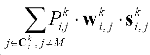
![]()

![]()
![]()
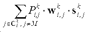
![]()
![]()
![]()
도 10은 본 발명의 또 다른 실시 예에 따라 기지국이 단말에게 단말의 서빙 기지국이 다중 사용자 장치에게 전송한 신호로 인해 발생한 간섭을 측정하게 하기 위하여 하나의 CSI-Process에 해당하는 IMR을 할당하는 방법을 나타내는 도면이다.10 is a diagram illustrating a method of allocating an IMR corresponding to one CSI-Process in order to allow a base station to measure an interference caused by a signal transmitted from a serving base station of a UE to a multi-user device according to another embodiment of the present invention Fig.
도 10을 참조하면, 본 발명에서 제안하는 단말 스스로가 수신해야 할 신호를 제거하여 간섭을 측정 하는 방법(하나의 IMR을 이용한 간섭 측정 방법 2)에 의해 eNB가 MU-MIMO 간섭측정을 위하여 단말들에게 PDSCH를 전송하고자 하는 단말들에 대한 신호를 IMR에 송신할 수 있다. Referring to FIG. 10, a method for measuring interference by removing a signal to be received by the terminal itself (an
도 10에서 eNB는 IMR A (1000)에 ![]()
![]()
하나의 IMR을 이용한 간섭 측정 방법 1과 마찬가지로 eNB가 특정 집합 ![]()

![]()
이 때, 단말은 IMR A에서 
상기에서 설명한 바와 같이 단말은 IMR A에서 수신한 신호에서 자신을 위한 신호를 제거해야만 정확한 MU-MIMO 간섭을 측정할 수 있다. 이를 위해서 단말은 자신의 신호를 먼저 판단하고 이를 IMR A에서 제거해야만 한다. 한 예로 M 번째 단말의 경우 다음의 수학식과 같이 수신신호를 처리하여 채널상태 정보를 생성해야 한다. As described above, the UE can accurately measure the MU-MIMO interference only by removing the signal for itself from the signal received in the IMR A. To do this, the terminal must first determine its signal and remove it from IMR A. For example, in the case of the M-th UE, channel state information should be generated by processing a received signal according to the following equation.
<수학식3>&Quot; (3) "
MU-MIMO 간섭신호: 
이를 위해서는 M 번째 단말은 ![]()
![]()
![]()
![]()
![]()
![]()
![]()
![]()
![]()
![]()
![]()
![]()
![]()
![]()
![]()
![]()
![]()
![]()
![]()
![]()
![]()
![]()
![]()
![]()
상기 ![]()
![]()
![]()
![]()
![]()
![]()
![]()
![]()
![]()
![]()
![]()
![]()
상기에서 언급한 바와 같이 ![]()
![]()
![]()
![]()
![]()
![]()
![]()
![]()
![]()
![]()
![]()
![]()
상기 ![]()
![]()
![]()
![]()
![]()
![]()
![]()
![]()
![]()
![]()
![]()
![]()
![]()
![]()
![]()
![]()
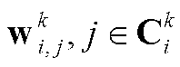
도 11은 본 발명의 또 다른 실시 예에 따라 기지국이 단말에게 단말의 서빙 기지국이 다중 사용자 장치에게 전송한 신호로 인해 발생한 간섭을 측정하게 하기 위하여 하나의 CSI-Process에 해당하는 IMR을 할당하는 방법을 나타내는 도면이다.11 is a diagram illustrating a method of allocating an IMR corresponding to one CSI-Process in order to measure an interference caused by a signal transmitted from a serving base station of a UE to a multi-user device, to a UE according to another embodiment of the present invention Fig.
도 11을 참조하면, 본 발명에서 제안하는 하나의 IMR을 이용한 간섭 측정 방법 1과 2를 혼용하여 간섭을 측정하는 방법(하나의 IMR을 이용한 간섭 측정 방법 3)에 의해 eNB가 MU-MIMO 간섭측정을 위하여 단말들에게 PDSCH를 전송하고자 하는 단말들에 대한 신호를 IMR에 송신할 수 있다. Referring to FIG. 11, it can be seen that the eNB can measure the MU-MIMO interference by measuring the interference using the one IMR-based
도 11에서 eNB는 IMR A (1100)에 M번째 단말이 받아야 할 신호와 함께 ![]()
![]()
하나의 IMR을 이용한 간섭 측정 방법 1, 2와 마찬가지로 eNB가 특정 집합 ![]()

![]()
이 때, 단말은 IMR A에서 
상기에서 설명한 바와 같이 단말은 IMR A에서 수신한 신호에서 자신을 위한 신호를 제거해야만 정확한 MU-MIMO 간섭을 측정할 수 있다. 이를 위해서 단말은 자신의 신호를 먼저 판단하고 이를 IMR A에서 제거해야만 한다. 한 예로 M 번째 단말의 경우 다음의 수학식과 같이 수신신호를 처리하여 채널상태 정보를 생성해야 한다.As described above, the UE can accurately measure the MU-MIMO interference only by removing the signal for itself from the signal received in the IMR A. To do this, the terminal must first determine its signal and remove it from IMR A. For example, in the case of the M-th UE, channel state information should be generated by processing a received signal according to the following equation.
<수학식4>&Quot; (4) "
MU-MIMO 간섭신호: 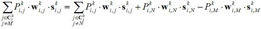
이를 위해서 하나의 IMR을 이용한 간섭 측정 방법 1, 2와 마찬가지로 M 번째 단말은 ![]()
![]()
![]()
![]()
![]()
![]()
![]()
![]()
![]()
![]()
![]()
![]()
![]()
![]()
![]()
![]()
![]()
![]()
![]()
![]()
![]()
![]()
![]()
![]()
![]()
![]()
또한, 하나의 IMR을 이용한 간섭 측정 방법 2와 마찬가지로 기지국이 자신에게 할당한 송신전력(![]()
![]()
![]()
![]()
![]()
![]()
![]()
![]()
![]()
![]()
![]()
![]()
본 발명에서 제안하는 CSI-Process별 IMR 정의 방법 2는 eNB가 기존 LTE Release 11에서와 달리 단말에 하나의 CSI-Process에 복수개의 IMR을 정의하여 MU-MIMO 간섭을 측정하는 방법이다. 다시 말해, 기존에는 하나의 CSI-RS와 하나의 IMR 자원을 이용하여 채널 상태를 보고하였던 반면에, 새로운 CSI-Process 에서는 하나의 CSI-Process는 기존과 달리 하나의 CSI-RS와 복수개의 IMR 자원을 통해 정의되며, CSI-RS와 복수개의 IMR 자원을 조합하여 다양한 채널 상황에 대하여 채널 상태를 보고하는 것이 가능하다.
The
도 12는 본 발명의 또 다른 실시 예에 따라 채널 상태 정보 보고를 하는 방법과 그 예시를 나타내는 도면이다. 12 is a diagram illustrating a method of reporting channel state information according to another embodiment of the present invention and an example thereof.
도 12를 참조하면, 하나의 CSI-Process에 하나의 CSI-RS와 복수개의 IMR을 포함할 수 있으며, CSI-Process마다 CSI-RS와 IMR의 조합을 달리하여 채널 상태 정보 보고를 할 수 있다..Referring to FIG. 12, one CSI-process may include one CSI-RS and a plurality of IMRs, and channel state information may be reported by using a combination of CSI-RS and IMR for each CSI-process. .
1200은 하나의 CSI-RS와 복수개의 IMR을 포함하는 CSI-Process를 예시한 것이다. 1200의 CSI-Process는 하나의 CSI-RS와 세 개의 IMR(1201, 1202, 1203)으로 구성되어 있다. 본 예시에서는 세 개의 IMR로 구성되어 있지만, 실제 사용에서 IMR의 개수는 세 개가 아닌 두 개 이상의 어떤 수로 설정하는 경우를 모두 포함한다. 1204의 report example 1은 1200의 CSI-Process가 정의되어 있다고 가정할 때, 이러한 CSI-Process를 이용하여 CSI-RS를 신호로 가정하고, IMR1(1205)의 파워를 간섭으로 가정하여 채널 상태를 보고하는 경우를 나타낸 것이다. 1206의 report example 2는 1200의 CSI-Process가 정의되어 있다고 가정할 때, 이러한 CSI-Process를 이용하여 CSI-RS를 신호로 가정하고, IMR2(1207)와 IMR3(1208)의 파워를 간섭으로 가정하여 채널 상태를 보고하는 경우를 나타낸 것이다. 마찬가지로, 1309의 report example 3은 1200의 CSI-Process가 정의되어 있다고 가정할 때, 이러한 CSI-Process를 이용하여 CSI-RS를 신호로 가정하고, 모든 IMR1,2,3(1210, 1211, 1212)의 파워를 간섭으로 가정하여 채널 상태를 보고하는 경우를 나타낸 것이다. 1200 is an example of a CSI-Process including one CSI-RS and a plurality of IMRs. The 1200 CSI-Process consists of one CSI-RS and three
이와 같이 하나의 CSI-Process에 복수개의 IMR을 설정하게 할 경우 다양한 경우의 수를 고려하여 채널 상태를 보고하도록 할 수 있다. 본 예시의 경우는 다양한 조합에 대한 경우의 수 중 하나의 IMR, 두 개의 IMR, 세 개의 IMR을 사용하여 채널 상태 정보 보고를 할 경우에 대하여 대표적인 경우를 도시한 것이며, 본 발명에서는 도시된 예시들 뿐만 아니라 하나의 CSI-RS와 복수 개의 IMR을 사용하여 채널 상태를 보고하는 모든 경우의 수를 포함한다.
When a plurality of IMRs are set in one CSI-process, the channel status can be reported considering the number of various cases. In the present example, a representative case is described in which channel state information is reported using one IMR, two IMRs, and three IMRs in the case of various combinations. In the present invention, As well as the number of all cases in which channel status is reported using one CSI-RS and multiple IMRs.
도 13은 본 발명의 또 다른 실시 예에 따라 기지국이 단말에게 단말의 서빙 기지국이 다중 사용자 장치에게 전송한 신호로 인해 발생한 간섭을 측정하게 하기 위하여 하나의 CSI-Process에 해당하는 IMR을 할당하는 방법을 나타내는 도면이다.13 is a diagram illustrating a method of allocating an IMR corresponding to one CSI-Process in order to measure interference caused by a signal transmitted from a serving base station of a UE to a multi-user device, to a UE according to another embodiment of the present invention Fig.
도 13을 참조하면, 본 발명에서 제안하는 복수개의 IMR에 해당하는 시간 및 주파수 자원을 단말에 간섭을 측정하기 위하여 정의하는 방법(CSI-Process별 IMR 정의 방법 2)에 의해 eNB가 MU-MIMO 간섭측정을 위하여 단말들에게 PDSCH를 전송하고자 하는 단말들에 대한 신호를 복수의 IMR에 송신할 수 있다. Referring to FIG. 13, by a method (
도 13에서 eNB는 하나의 CSI-Process에 복수 개의 IMR을 이용하여 간섭을 측정한다. eNB가 특정 집합 ![]()
![]()
![]()
![]()
![]()
![]()
![]()
![]()
![]()
![]()
상기 도 13과 같이 본 발명에서 제안하는 각각의 CSI-Process별 IMR 정의 방법 2를 이용하여 MU-MIMO 간섭을 측정하는 방법은 다음과 같다. 본 발명에서 제안하는 단말의 간섭을 측정하기 위하여 정의된 복수 개의 IMR을 이용하여 간섭을 측정하는 방법은 복수의 IMR에서 적어도 하나의 IMR을 선택하는 것을 포함할 수 있다.As shown in FIG. 13, a method for measuring MU-MIMO interference using the
·복수 개의 IMR을 이용한 간섭 측정 방법 1: 복수 개의 IMR 중 하나의 IMR을 선택하여 간섭을 측정 후 채널 정보를 생성Method of measuring interference using a plurality of IMRs 1: Select one IMR among a plurality of IMRs to measure interference and generate channel information
·복수 개의 IMR을 이용한 간섭 측정 방법 2: 복수 개의 IMR 중 복수 개의 IMR을 선택하여 간섭을 측정 후 채널 정보를 생성
Method of measuring interference using a plurality of IMRs 2: Selecting a plurality of IMRs among a plurality of IMRs to measure interference and generate channel information
도 14은 본 발명의 또 다른 실시 예에 따라 기지국이 단말에게 단말의 서빙 기지국이 다중 사용자 장치에게 전송한 신호로 인해 발생한 간섭을 측정하게 하기 위하여 하나의 CSI-Process에 해당하는 IMR을 할당하는 방법을 나타내는 도면이다.14 is a diagram illustrating a method of allocating an IMR corresponding to one CSI-Process in order to measure interference generated due to a signal transmitted from a serving base station of a UE to a multi-user device, to a UE according to another embodiment of the present invention Fig.
도 14를 참조하면, 본 발명에서 제안하는 복수 개의 IMR 중 하나의 IMR을 선택하여 간섭을 측정 하는 방법(복수 개의 IMR을 이용한 간섭 측정 방법 1)에 의해 eNB가 MU-MIMO 간섭측정을 위하여 단말들에게 PDSCH를 전송하고자 하는 단말들에 대한 신호를 IMR에 송신할 수 있다.. Referring to FIG. 14, an eNB selects an IMR among a plurality of IMRs proposed by the present invention to measure interference (
도 14에서 eNB는 하나의 CSI-Process에 복수 개의 IMR을 이용하여 간섭을 측정한다. 상기의 예시에서 eNB는 MU-MIMO 전송시의 간섭을 측정하기 위하여 도 14에 위치한 각각의 IMR (1400, 1410, 1420)에 주파수 및 시간 자원을 분리해서 단말들을 집합 ![]()
![]()
![]()
![]()
![]()
![]()
![]()
![]()


![]()
![]()
![]()
![]()
![]()
![]()
![]()
![]()
복수 개의 IMR 중 복수 개의 IMR을 선택하여 간섭을 측정하는 방법(복수 개의 IMR을 이용한 간섭 측정 방법 2)을 이용하여 복수 개의 IMR 중 복수 개의 IMR을 선택하여 간섭을 측정 후 채널 정보를 생성하는 경우 다음과 같은 방법을 이용하여 복수 개의 IMR을 선택하고 간섭을 측정할 수 있다.When a plurality of IMRs are selected from a plurality of IMRs by using a method of measuring interference (plurality of IMR-based interference measurement method 2) by selecting a plurality of IMRs among a plurality of IMRs and generating channel information after measuring interference, To select a plurality of IMRs and measure the interference.
·복수 개의 IMR 중 복수 개의 IMR을 이용한 간섭 측정 방법 1: 복수 개의 IMR의 간섭을 포함하여 간섭을 측정Method for measuring interference using a plurality of IMRs among a plurality of IMRs 1: Measurement of interference including interference of a plurality of IMRs
·복수 개의 IMR 중 복수 개의 IMR을 이용한 간섭 측정 방법 2: 복수 개의 IMR의 간섭을 제거하여 간섭을 측정Method of measuring interference using a plurality of IMRs among a plurality of IMRs Method 2: Measuring interference by removing interference of a plurality of IMRs
·복수 개의 IMR 중 복수 개의 IMR을 이용한 간섭 측정 방법 3: 복수 개의 IMR의 간섭을 각각 포함 혹은 제거하여 간섭을 측정
Method of measuring interference using a plurality of IMRs among a plurality of IMRs 3: Measurement of interference by including or removing interference of a plurality of IMRs
도 15는 본 발명의 또 다른 실시 예에 따라 기지국이 단말에게 단말의 서빙 기지국이 다중 사용자 장치에게 전송한 신호로 인해 발생한 간섭을 측정하게 하기 위하여 하나의 CSI-Process에 해당하는 IMR을 할당하는 방법을 나타내는 도면이다.15 is a diagram illustrating a method of allocating an IMR corresponding to one CSI-Process in order to allow a BS to measure an interference caused by a signal transmitted from a serving BS of a UE to a multi-user device according to another embodiment of the present invention Fig.
도 15를 참조하면 본 발명에서 제안하는 복수 개의 IMR 중 복수 개의 IMR의 간섭을 포함하여 간섭을 측정하는 방법(복수 개의 IMR 중 복수 개의 IMR을 이용한 간섭 측정 방법 1)에 의해 eNB가 MU-MIMO 간섭측정을 위하여 단말들에게 PDSCH를 전송하고자 하는 단말들에 대한 신호를 IMR에 송신할 수 있다. Referring to FIG. 15, a method of measuring interference including interference of a plurality of IMRs among a plurality of IMRs proposed in the present invention (
도 15에서 eNB는 하나의 CSI-Process에 복수 개의 IMR을 이용하여 간섭을 측정한다. 상기의 예시에서 eNB는 MU-MIMO 전송시의 간섭을 측정하기 위하여 도 15에 위치한 각각의 IMR (1500, 1510, 1520)에 주파수 및 시간 자원을 분리해서 단말들을 집합 ![]()
![]()
![]()
![]()
![]()
![]()
![]()
![]()
![]()
![]()
![]()
![]()
![]()
![]()
<수학식5>Equation (5)
MU-MIMO 간섭신호: 
단말 2와 3의 경우에도 마찬가지로 각각 IMR A와 IMR C, IMR A와 IMR B의 간섭을 함께 고려하여 각각 단말 1, 3과 단말 1, 2에 해당하는 간섭인 

Similarly, in the case of
도 16은 본 발명의 또 다른 실시 예에 따라 기지국이 단말에게 단말의 서빙 기지국이 다중 사용자 장치에게 전송한 신호로 인해 발생한 간섭을 측정하게 하기 위하여 하나의 CSI-Process에 해당하는 IMR을 할당하는 방법을 나타내는 도면이다.16 is a diagram illustrating a method of allocating an IMR corresponding to one CSI-Process in order to measure interference generated due to a signal transmitted from a serving base station of a UE to a multi-user device, to a UE according to another embodiment of the present invention Fig.
도 16을 참조하면, 본 발명에서 제안하는 복수 개의 IMR의 간섭을 제거하거나 제거와 포함을 동시에 하여 간섭을 측정하는 방법(복수 개의 IMR 중 복수 개의 IMR을 이용한 간섭 측정 방법 2와 3)에 의해 eNB가 MU-MIMO 간섭측정을 위하여 단말들에게 PDSCH를 전송하고자 하는 단말들에 대한 신호를 IMR에 송신할 수 있다. Referring to FIG. 16, a method (
도 16에서 eNB는 하나의 CSI-Process에 복수 개의 IMR을 이용하여 간섭을 측정한다. 상기의 예시에서 eNB는 MU-MIMO 전송시의 간섭을 측정하기 위하여 도 16에 위치한 각각의 IMR (1600, 1610, 1620)에 주파수 및 시간 자원을 분리해서 단말들을 집합 ![]()
![]()
![]()
![]()
![]()
![]()
![]()
![]()
![]()
![]()
![]()
![]()
![]()
![]()
<수학식6>&Quot; (6) "
MU-MIMO 간섭신호: 
단말 2의 경우에도 마찬가지로 IMR A(1600)에서 IMR C(1620)의 간섭을 제거하여 고려하여 각각 단말 1, 3 에 해당하는 간섭을 고려하여 를 계산하고 이를 바탕으로 하여 채널 정보를 생성하도록 한다. 그러나, 이 경우 IMR A(1600)에서 IMR B(1610)와 IMR C(1620)의 간섭을 제거하여 계산하는 것 만으로는 모든 경우에 따라 해당 간섭을 생성할 수 없으며, 따라서 복수 개의 IMR을 이용한 간섭 측정 방법 3을 이용하여 복수 개의 IMR을 각각 간섭을 포함하고 제거하는 것이 포함된 방법이 필요하다. 이와 같은 방식으로 IMR B(1610)와 IMR C(1620)의 간섭을 고려하여 채널 상태 정보를 생성할 경우 아래 수학식 7과 같다.Similarly, in the case of the
<수학식7>&Quot; (7) "
MU-MIMO 간섭신호: 
이러한 복수 개의 IMR을 이용한 간섭 측정 방법 2와 3을 이용하여 MU-MIMO 동작에 필요한 채널 정보를 얻는 방법의 경우 하나의 CSI-process에 포함되는 IMR이 많으면 많을수록 더 많은 경우의 다중 사용자 환경에 대하여 채널 정보를 얻을 수 있기 때문에 채널 정보의 정확성 면에서 유리할 수 있다. 하지만, IMR을 많이 설정하는 것은 설정에 따르는 오버헤드(overhead)가 따르며 또한 IMR 자원을 할당하여야 하기 때문에 시간 및 주파수 자원 활용 측면에서도 효율적이지 못하다. 또한, LTE Rel. 11 단말의 경우 한 단말에 설정 가능한 IMR의 수를 3개까지로 제한하기 때문에 표준 측면에서도 제약이 있다. 따라서, 이러한 시간 및 주파수 자원의 제약과 설정 overhead의 효율성을 보완하기 위하여 대표적인 간섭을 IMR로 송신하여 선택하고, 상기에서 설명한 하나의 IMR을 이용한 간섭 측정 방법 1, 2, 3과 마찬가지로 MU-MIMO 동작에 필요한 채널 정보를 생성함에 있어 해당 단말의 신호 성분을 간섭에서 제외하거나 IMR에 포함되지 않는 경우에 해당하는 단말의 신호 성분을 간섭으로 만들어 포함하거나 혹은 IMR에 포함되었으나 co-scheduling되지 않는 단말의 간섭 성분을 간섭에서 제거하여 사용하는 경우가 함께 적용될 수 있다. In the method of obtaining the channel information necessary for the MU-MIMO operation by using the
상기에서 설명한 바와 같이 CSI-Process별 IMR 정의 방법 1을 이용하여 간섭을 측정하기 해서는 간섭에 해당하는

![]()
![]()
![]()
![]()
![]()
![]()
![]()
![]()
![]()
![]()
![]()
![]()
![]()
![]()
![]()
![]()
![]()

![]()
![]()
![]()
![]()
![]()
![]()
![]()
![]()
![]()
![]()
![]()
![]()
![]()
![]()
![]()
![]()
![]()
CSI-Process별 IMR 정의 방법 2를 이용하여 간섭을 측정하기 위해서는 해당 간섭 측정에 어떤 하나의 혹은 복수의 IMR을 선택할 것인지 그리고 복수의 IMR을 선택할 경우 해당 간섭을 추가로 포함할 것인지 혹은 해당 간섭을 기존 간섭에 제거하여 포함할 것인지에 대한 정보가 필요하다. 그리고 CSI-Process별 IMR 정의 방법 2에 해당하는 방법에 CSI-Process별 IMR 정의 방법 1의 방법을 추가적으로 사용할 경우에는 앞서 언급했던 바와 같이 간섭에 해당하는 

단말은 상기에서 언급한 신호 및 간섭 PMI 및 IMR 정보를 다음과 같은 방법을 사용하여 획득할 수 있다.The UE can acquire the above-mentioned signal and the interference PMI and IMR information using the following method.
·PMI 및 IMR 관련 정보 획득 방법 1: 표준에 사전에 정의· PMI and IMR related information acquisition method 1: Predefined in the standard
·PMI 및 IMR 관련 정보 획득 방법 2: RRC signaling을 통해 사전에 정의· PMI and IMR related information acquisition method 2: Predefined through RRC signaling
·PMI 및 IMR 관련 정보 획득 방법 3: RRC signaling을 통해 aperiodic CSI trigger table에 해당 정보를 mapping하고, 해당 정보를 기반으로 하여 aperiodic CSI trigger를 통해 해당 정보 전달· PMI and IMR related information acquisition method 3: Mapping the information to the aperiodic CSI trigger table through RRC signaling, and based on the information, the information is transmitted through the aperiodic CSI trigger
·PMI 및 IMR 관련 정보 획득 방법 4: Dynamic signaling을 통해 전달· PMI and IMR related information acquisition method 4: Dynamic signaling
표 2-1과 표 2-2는 표준에 사전에 정의하여 PMI 및 IMR 관련 정보를 획득하는 방법(PMI 및 IMR 관련 정보 획득 방법 1)을 설명하기 위하여 간섭 PMI 및 IMR을 구성하기 위한 규칙을 예시한 것이다. Table 2-1 and Table 2-2 show the rules for constructing the interfering PMI and IMR to explain how to obtain PMI and IMR related information (PMI and IMR related information acquisition method 1) by defining in advance in the standard It is.
<표 2-1> 간섭 precoder ![]()
![]()

<표 2-2> 간섭 precoder ![]()
![]()

<표 2-3> 하나의 간섭 IMR 에 대한 규칙의 예시<Table 2-3> Example of rules for one interference IMR
<표 2-4> 복수의 간섭 IMR 에 대한 규칙의 예시<Table 2-4> Examples of Rules for Multiple Interference IMRs

단말은 자신이 eNB에 보고한 PMI 값에 따라 eNB가 precoding을 적용하였다고 가정하고 이를 자신이 최근에 CSI-RS를 수신하여 채널 추정(channel estimation)을 통하여 얻은 채널 추정치와 결합하여 ![]()
![]()
![]()
![]()
![]()
![]()
![]()
![]()
![]()
![]()
![]()
![]()
![]()
![]()
![]()
![]()
PMI 및 IMR 관련 정보 획득 방법 2는 상기에서 언급한 규칙들을 RRC signalling을 통하여 전달하는 방법이다. 기본적인 규칙들은 표준에 사전에 정의하여 놓은 PMI 및 IMR 관련 정보 획득 방법 1과 유사할 수도 있고 다를 수도 있다. 유사한 경우 상기의 표 2-1~4에서 언급 된 규칙들을 Rel. 11의 PMI 제한(restriction) 설정과 유사한 필드를 각 PMI 별로 설정하여 공동 스케쥴링(co-scheduling) 가능한 PMI를 설정하도록 할 수 있으며, 각각의 PMI에 간섭을 포함하거나 제거해야 할 IMR을 설정하는 필드를 사용함으로써 간섭을 포함하거나 제거해야 할 IMR에 대하여 설정할 수 있다. 또한, 상기에서 언급한 바와 다르게 직접적으로 알릴 수도 있다. PMI and IMR related
예를 들어 ![]()
![]()
PMI 및 IMR 관련 정보 획득 방법 3은 RRC signaling을 통해 aperiodic CSI trigger table에 해당 정보를 mapping하고, 해당 정보를 기반으로 하여 aperiodic CSI trigger를 통해 해당 정보를 전달하는 방법이다. 표 3-1과 3-2는 PMI 및 IMR 관련 정보 획득 방법 3을 이용하여 간섭 PMI 및 IMR을 지정하기 위한 비주기적 채널 상태 피드백 지시자를 예시한 것이다.
PMI and IMR related
<표 3-1> 두 비트 비주기적 피드백 지시자(CSI Request Field)를 통한 간섭 PMI(interfering PMI) 지정 및 비주기적 피드백(aperiodic feedback) 수행 방법Table 3-1 Interfering PMI (Interfering PMI) Specification and Performing Aperiodic Feedback Through CSI Request Fields with Two Bits

<표 3-2> 두 비트 비주기적 피드백 지시자(CSI Request Field)를 통한 IMR 지정 및 비주기적 피드백(aperiodic feedback) 수행 방법<Table 3-2> IMR designation and aperiodic feedback through two bit non-periodic feedback indicator (CSI Request Field)

표 3-1은 PMI 및 IMR 관련 정보 획득 방법 3을 이용하여 기지국이 원하는 간섭으로 판단할 PMI와 함께 MU-CSI report를 단말에게 지시하는 방법이다. 필드 '00' 은 비주기적 채널 상태 정보 보고가 필요 없을 때를 의미하는 것이며, '01'은 단말이 기존의 비주기적 채널 상태 정보 보고를 지시했던 것과 동일하게 간섭 PMI에 대한 추가적인 고려 없이 CSI-RS와 IMR을 이용하여 기존의 방법으로 채널 상태를 보고 할 것을 지시하는 것을 의미한다. 필드 '10'과 '11'의 경우는 RRC를 이용하여 간섭(interfering) PMI set 1과 2를 설정하고, 비주기적 피드백 지시자(CSI Request Field)를 통하여 해당 PMI 들을 간섭 PMI로 설정하고, 간섭 PMI 들에 대한 간섭을 도출하여 IMR 과 함께 간섭으로 고려하는 것을 의미한다. 해당 표 3-1은 간섭 PMI 들에 대해서만 언급하고 있지만, 'interfereing and not co-scheduled PMI set'과 같이 언급하고, RRC에 해당 set 들에 대하여 간섭에 포함할 PMI와 간섭에서 제거 될 PMI를 구분하여 설정 후 이용하는 것도 가능하다.Table 3-1 is a method for instructing the UE with the MU-CSI report together with the PMI to be determined as a desired interference by the base station using the PMI and IMR related
상기 표 3-2 에서와 같이 기지국은 비주기적 채널 상태 정보 보고(aperiodic channel status information reporting)를 위하여 해당 IMR 집합과 함께 MU-MIMO 동작을 위한 비주기적 채널 상태 정보 보고를 지시할 수 있다. 상기의 SU-PMI 와 MU-PMI 간의 offset 지시 방법들과 마찬가지로 각각의 표에서의 필드 '00'은 비주기적 채널 상태 정보 보고가 필요 없을 때를 의미하는 것이며, '01' 모든 IMR을 한꺼번에 고려하여 채널 상태를 보고하는 것을 나타낸다. 필드 '10'과 '11'의 경우는 RRC를 이용하여 간섭(interfering) IMR set 1과 2를 설정하고, 비주기적 피드백 지시자(CSI Request Field)를 통하여 해당 IMR 들을 간섭 IMR로 설정하고, 해당 간섭 IMR 들의 간섭을 고려하여 채널 상태 정보를 생성하는 것을 의미한다. 해당 표 3-2는 간섭 IMR 들에 대해서만 언급하고 있지만, 'interfereing and not co-scheduled or signalling IMR set'과 같이 언급하고, RRC에 해당 set 들에 대하여 간섭에 포함할 IMR 집합과 간섭에서 제거 될 IMR 집합을 구분하여 설정 후 이용하는 것도 가능하다. As shown in Table 3-2, the BS may instruct the aperiodic channel status information reporting for the MU-MIMO operation together with the corresponding IMR set for aperiodic channel status information reporting. Like the offset indication methods between the SU-PMI and the MU-PMI, the field '00' in each table means that no reporting of the aperiodic channel state information is required, and all IMRs of '01' Indicates that the channel status is reported. In the case of the fields '10' and '11', the interfering IMR sets 1 and 2 are set using the RRC, the corresponding IMRs are set as the interference IMR through the CSI request field, Which means that channel state information is generated in consideration of interference of IMRs. In Table 3-2, we refer to interfering IMRs as 'interfereing and not co-scheduled or signaling IMR set'. We refer to the RRC as a set of IMRs to be included in the interference and IMR It is also possible to set and use the sets separately.
상기 표 3-1과 3-2의 예시는 2비트 정보를 이용한 비주기적 피드백 지시자만을 예시하고 있지만, 응용에 따라 1비트 혹은 3비트 이상의 피드백 지시자에도 유사하게 적용 가능하며, 많은 비트를 이용할 경우 기존의 CA(Carrier Aggregation)나 CoMP(Coordinated Multi- Point transmission and reception) 동작을 위한 비주기적 피드백 지시자(CSI Request Field)와 간섭 PMI 및 IMR 정보를 함께 전달하는 비주기적 피드백 지시자가 결합된 형태로도 이용 가능하다.Although the examples of Tables 3-1 and 3-2 illustrate only the aperiodic feedback indicator using 2-bit information, it can be similarly applied to 1-bit or 3-bit feedback indicators depending on the application. Periodic feedback indicator (CSI Request Field) for CA (Carrier Aggregation) or Coordinated Multipoint transmission and reception (CoMP) operation and an aperiodic feedback indicator for communicating the interference PMI and IMR information together It is possible.
PMI 및 IMR 관련 정보 획득 방법 4는 기지국이 직접적으로 단말에게 알려주는 방식이다. 이 경우 새로운 DCI 필드가 추가되어야 하며, 이러한 정보를 받은 단말은 이를 이용하여 해당 정보를 파악할 수 있다. 예를 들어 ![]()
![]()
또한 상기의 예시들에서 각각의 IMR과 PMI를 통한 간섭은 1:1로 동일한 비율로 혹은 다음의 수학식8와 같이 일정한 비율을 적용하여 합치는 것이다.Also, in the above examples, interference between each IMR and PMI is equal to 1: 1 at the same rate or by applying a certain ratio as shown in Equation (8).
<수학식8>&Quot; (8) "

상기 수학식 8에서 ![]()
![]()
![]()
![]()
![]()
![]()
![]()
![]()
도 17은 본 발명에 따라 단말에게 MU-CSI report를 지시하는 기지국의 동작을 설명한 도면이다.17 is a view for explaining an operation of a base station indicating a MU-CSI report to a terminal according to the present invention.
도 17을 참조하면, 기지국은 단말이 MU-CSI report가 필요한 상황을 파악(1700)하여 MU-CSI report를 위한 간섭 PMI 및 IMR 관련 정보를 설정 및 전달(1710)하고, 이를 이용하여 단말로부터 MU-CSI report를 수신(1720)할 수 있다.Referring to FIG. 17, the BS detects (1700) a situation in which the MS needs to report an MU-CSI and sets and transmits the interference PMI and IMR related information for the MU-CSI report (1710) The CSI report can be received (1720).
도 17의 과정 1700에서 기지국은 단말이 그 동안 기지국에 보고한 주기적, 비주기적 채널 상태 정보 보고, 다른 단말의 채널 상태 정보 보고, 현재 기지국의 로딩(loading) 등 다양한 요소를 고려하여 단말에게 MU-CSI report를 위한 비주기적 채널 상태 정보 보고가 이루어져야 할 필요가 있는 지를 파악한다. 과정 1710에서 과정 1700에서 파악한 결과를 토대로 사용을 설정할지를 결정하고 상기에서 설명한 RRC, L1 signalling 등을 통해 필요 정보를 단말에 전달한다. 과정 1720에서 이러한 정보를 받은 단말에게 비주기적 채널 상태 정보 보고를 지시함으로써 해당 MU-CSI report를 수신한다.In
도 18은 본 발명에 따라 기지국에게 MU-CSI report 하는 단말의 동작을 설명한 도면이다.18 is a diagram illustrating an operation of a terminal reporting an MU-CSI to a base station according to the present invention.
도 18을 참조하면, 단말이 기지국으로부터 MU-CSI report를 위한 간섭 PMI 및 IMR 관련 정보를 수신하고(1800), 이를 이용하여 단말로부터 MU-CSI를 보고(1810)할 수 있다.Referring to FIG. 18, the UE can receive (1800) the interference PMI and IMR related information for the MU-CSI report from the base station, and report (1810) the MU-CSI from the UE using the interference PMI and IMR related information.
도 18의 과정 1800에서 단말은 기지국으로부터 MU-CSI report를 위한 간섭 PMI 및 IMR 관련 정보를 전달 받는다. 과정 1810에서 단말이 기지국으로부터 MU-MIMO 동작을 위한 비주기적 채널 상태 보고 수행 지시를 수신 하면 단말은 기지국이 전달한 간섭 PMI 및 IMR 관련 정보를 바탕으로 채널 상태 정보를 만들고 이를 이용하여 채널 상태 보고를 수행하게 된다. In
도 19는 본 발명에 따라 기지국 내부 구조를 도시하는 블록도이다.
19 is a block diagram showing the internal structure of a base station according to the present invention.
도 19에서 기지국 제어기 2200은 기지국에 할당 된 단말들의 주기적, 비주기적 채널 상태 정보 보고 및 트래픽(traffic), 이동 상태 등을 고려하여 단말에게 MU-CSI를 위해 적합한 간섭 PMI 및 IMR 정보를 장치 1910을 통해 설정한다. 이 후 기지국 제어기는 채널 상태 정보 보고를 장치 1910을 이용하여 통보한다. 기지국은 단말이 측정하여 보고하는 채널상태 정보를 장치 1920을 이용하여 수신한다. 수신한 채널상태 정보는 장치 1900의 기지국 제어기에서 적합한 채널상태 정보인지 판단된 후 기지국의 하향링크에 대한 무선자원 관리에 활용된다.In FIG. 19, the BSC 2200 notifies the UE of interference PMI and IMR information suitable for MU-CSI to the
도 20은 본 발명에 따라 단말의 내부 구조를 도시하는 블록도이다.20 is a block diagram showing an internal structure of a terminal according to the present invention.
도 20를 참조하면, 단말 장치는 단말 제어기(2000), 송신기(2010) 및 수신기(2020)를 포함할 수 있다.Referring to FIG. 20, a terminal device may include a
도 20에서 단말 제어기 2000은 장치 2020을 이용하여 기지국으로부터 MU-CSI 보고를 간섭 PMI 및 IMR 관련 정보를 수신한다. 이후 단말은 장치 2020에서 하향링크에 대한 신호를 수신하고 이와 기지국으로부터 받은 간섭 PMI 및 IMR 정보를 이용하여 단말 제어기에서 채널상태 정보(CSI report)를 생성한다. 생성된 채널상태 정보는 장치 2010을 이용하여 기지국으로 통보된다.In FIG. 20, the
한편, 본 명세서와 도면에는 본 발명의 바람직한 실시 예에 대하여 개시하였으며, 비록 특정 용어들이 사용되었으나, 이는 단지 본 발명의 기술 내용을 쉽게 설명하고 발명의 이해를 돕기 위한 일반적인 의미에서 사용된 것이지, 본 발명의 범위를 한정하고자 하는 것은 아니다. 여기에 개시된 실시 예 외에도 본 발명의 기술적 사상에 바탕을 둔 다른 변형 예들이 실시 가능하다는 것은 본 발명이 속하는 기술 분야에서 통상의 지식을 가진 자에게 자명한 것이다.
While the present invention has been particularly shown and described with reference to exemplary embodiments thereof, it is to be understood that the invention is not limited to the disclosed embodiments, but, on the contrary, And is not intended to limit the scope of the invention. It is to be understood by those skilled in the art that other modifications based on the technical idea of the present invention are possible in addition to the embodiments disclosed herein.
Claims (20)
단말의 서빙 기지국이 다중 사용자 장치에게 전송한 신호로 인해 발생한 간섭을 측정하기 위한 정보를 설정하는 단계;
상기 설정한 정보를 단말에 전달하는 단계; 및
상기 정보를 기반으로 측정된 간섭을 이용하여 생성된 채널상태 정보를 단말로부터 수신하는 단계를 포함하는 것을 특징으로 하는 기지국이 단말의 채널 상태 정보 보고 시에 간섭을 측정하게 하는 방법.A method for measuring interference in a mobile communication system when a base station reports channel state information of a mobile station,
Setting information for measuring interference caused by a signal transmitted from a serving base station of a mobile subscriber station to a multi user device;
Transmitting the set information to a terminal; And
And receiving channel state information generated using interference measured based on the information, from the terminal. The method of claim 1, wherein the base station measures interference when reporting channel state information of the terminal.
상기 단말의 서빙 기지국이 다중 사용자 장치에게 전송한 신호로 인해 발생한 간섭은,
상기 단말에 대해 한 개의 IMR(Interference Measurement Resource)이 설정된 경우, 상기 단말 이외의 단말로 전달되어 상기 단말의 간섭에 해당하는 신호를 추가 또는 상기 단말의 수신해야 할 신호를 제거하는 방법으로 생성되는 것을 특징으로 하는 기지국이 단말의 채널 상태 정보 보고 시에 간섭을 측정하게 하는 방법.The method according to claim 1,
The interference caused by the signal transmitted from the serving BS to the multi-
When an IMR (Interference Measurement Resource) is set for the UE, the signal is transmitted to a UE other than the UE, and a signal corresponding to interference of the UE is added or a signal to be received by the UE is removed Wherein the base station measures the interference when reporting channel state information of the terminal.
상기 단말의 서빙 기지국이 다중 사용자 장치에게 전송한 신호로 인해 발생한 간섭을 측정하기 위한 정보는,
상기 단말에 대해 복수의 IMR이 설정된 경우, 적어도 하나의 IMR을 선택하는 정보를 포함하는 것을 특징으로 하는 기지국이 단말의 채널 상태 정보 보고 시에 간섭을 측정하게 하는 방법..The method according to claim 1,
The information for measuring the interference caused by the signal transmitted from the serving base station to the multi-
And selecting at least one IMR when a plurality of IMRs are set for the MS. The method of claim 1, wherein the BS measures interference at the time of reporting channel state information of the MS.
상기 설정한 정보를 전달하는 단계는,
RRC(Radio Resource Control) signaling을 통하여 전달하는 것을 특징으로 하는 기지국이 단말의 채널 상태 정보 보고 시에 간섭을 측정하게 하는 방법.The method according to claim 1,
Wherein the step of transmitting the set information comprises:
(RRC) signaling. The method of claim 1, wherein the base station measures interference when reporting channel state information of the UE.
상기 설정한 정보를 전달하는 단계는,
비주기적 피드백 지시자를 통하여 전달하는 것을 특징으로 하는 기지국이 단말에게 채널 상태 정보 보고를 지시하는 방법.The method according to claim 1,
Wherein the step of transmitting the set information comprises:
Wherein the base station reports the channel state information to the UE.
단말의 서빙 기지국이 다중 사용자 장치에게 전송한 신호로 인해 발생한 간섭을 측정하기 위한 정보를 기지국으로부터 수신하는 단계;
상기 정보를 기반으로 간섭을 측정하는 단계;
상기 측정된 간섭을 이용하여 채널상태 정보를 생성하는 단계; 및
상기 생성한 채널상태 정보를 기지국으로 전달하는 단계를 포함하는 것을 특징으로 하는 단말의 채널 상태 정보 보고 시에 간섭을 측정하는 방법.A method for measuring interference in reporting a channel state information of a terminal in a mobile communication system,
Receiving from a base station information for measuring an interference caused by a signal transmitted from a serving base station of a mobile subscriber station to a multi-user subscriber station;
Measuring interference based on the information;
Generating channel state information using the measured interference; And
And transmitting the generated channel state information to the base station.
상기 단말의 서빙 기지국이 다중 사용자 장치에게 전송한 신호로 인해 발생한 간섭은,
상기 단말에 대해 한 개의 IMR(Interference Measurement Resource)이 설정된 경우, 상기 단말 이외의 단말로 전달되어 상기 단말의 간섭에 해당하는 신호를 추가 또는 상기 단말의 신호를 제거하는 방법으로 생성되는 것을 특징으로 하는 단말의 채널 상태 정보 보고 시에 간섭을 측정하는 방법.The method according to claim 6,
The interference caused by the signal transmitted from the serving BS to the multi-
When an IMR (Interference Measurement Resource) is set for the MS, the MS transmits the signal to the MS other than the MS, and adds a signal corresponding to the interference of the MS or removes the signal of the MS. A method for measuring interference when reporting channel state information of a terminal.
상기 단말의 서빙 기지국이 다중 사용자 장치에게 전송한 신호로 인해 발생한 간섭을 측정하기 위한 정보는,
상기 단말에 대해 복수의 IMR이 설정된 경우, 적어도 하나의 IMR을 선택하는 정보를 포함하는 것을 특징으로 하는 단말의 채널 상태 정보 보고 시에 간섭을 측정하는 방법.The method according to claim 6,
The information for measuring the interference caused by the signal transmitted from the serving base station to the multi-
And selecting at least one IMR when a plurality of IMRs are set for the UE.
상기 설정한 정보를 수신하는 단계는,
RRC(Radio Resource Control) signaling을 통하여 수신하는 것을 특징으로 하는 단말의 채널 상태 정보 보고 시에 간섭을 측정하는 방법.The method according to claim 6,
Wherein the step of receiving the set information comprises:
(RRC) signaling. The method of claim 1, wherein the at least one of the plurality of antennas comprises a plurality of antennas.
상기 설정한 정보를 수신하는 단계는,
비주기적 피드백 지시자를 통하여 수신하는 것을 특징으로 하는 단말의 채널 상태 정보 보고 시에 간섭을 측정하는 방법.The method according to claim 6,
Wherein the step of receiving the set information comprises:
Wherein the interference is received through an aperiodic feedback indicator.
단말과 신호를 송수신하는 송수신부; 및
단말의 서빙 기지국이 다중 사용자 장치에게 전송한 신호로 인해 발생한 간섭을 측정하기 위한 정보를 설정하고, 상기 설정한 정보를 단말에 전달하고, 상기 정보를 기반으로 측정된 간섭을 이용하여 생성된 채널상태 정보를 단말로부터 수신하는 것을 제어하는 제어부를 포함하는 것을 특징으로 하는 기지국.1. A base station for measuring interference in reporting a channel state information of a terminal in a mobile communication system,
A transmitting and receiving unit for transmitting and receiving signals to and from the terminal; And
The method comprising: setting information for measuring interference caused by a signal transmitted from a serving base station of a mobile station to a multi-user device, transmitting the set information to the mobile station, And a control unit for controlling reception of information from the terminal.
상기 단말의 서빙 기지국이 다중 사용자 장치에게 전송한 신호로 인해 발생한 간섭은,
상기 단말에 대해 한 개의 IMR(Interference Measurement Resource)이 설정된 경우, 상기 단말 이외의 단말로 전달되어 상기 단말의 간섭에 해당하는 신호를 추가 또는 상기 단말의 수신해야 할 신호를 제거하는 방법으로 생성되는 것을 특징으로 하는 기지국.12. The method of claim 11,
The interference caused by the signal transmitted from the serving BS to the multi-
When an IMR (Interference Measurement Resource) is set for the UE, the signal is transmitted to a UE other than the UE, and a signal corresponding to interference of the UE is added or a signal to be received by the UE is removed Characterized in that the base station.
상기 단말의 서빙 기지국이 다중 사용자 장치에게 전송한 신호로 인해 발생한 간섭을 측정하기 위한 정보는,
상기 단말에 대해 복수의 IMR이 설정된 경우, 적어도 하나의 IMR을 선택하는 정보를 포함하는 것을 특징으로 하는 기지국.12. The method of claim 11,
The information for measuring the interference caused by the signal transmitted from the serving base station to the multi-
And selecting at least one IMR when a plurality of IMRs are set for the terminal.
상기 설정한 정보를 전달하는 것은,
RRC(Radio Resource Control) signaling을 통하여 전달하는 것을 특징으로 하는 기지국.12. The method of claim 11,
To transmit the set information,
RRC (Radio Resource Control) signaling.
상기 설정한 정보를 전달하는 것은,
비주기적 피드백 지시자를 통하여 전달하는 것을 특징으로 하는 기지국.12. The method of claim 11,
To transmit the set information,
And transmits the signal through an aperiodic feedback indicator.
기지국과 신호를 송수신하는 송수신부; 및
단말의 서빙 기지국이 다중 사용자 장치에게 전송한 신호로 인해 발생한 간섭을 측정하기 위한 정보를 기지국으로부터 수신하고, 상기 정보를 기반으로 간섭을 측정하고, 상기 측정된 간섭을 이용하여 채널상태 정보를 생성하고, 상기 생성한 채널상태 정보를 기지국으로 전달하는 것을 제어하는 제어부를 포함하는 것을 특징으로 하는 단말.1. A terminal for measuring interference at the time of reporting channel state information in a mobile communication system,
A transmission / reception unit for transmitting / receiving signals to / from a base station; And
The method includes receiving information for measuring interference caused by a signal transmitted from a serving base station of a mobile station to a multi-user device from a base station, measuring interference based on the information, generating channel state information using the measured interference, And a controller for controlling transmission of the generated channel state information to a base station.
상기 단말의 서빙 기지국이 다중 사용자 장치에게 전송한 신호로 인해 발생한 간섭은,
상기 단말에 대해 한 개의 IMR(Interference Measurement Resource)이 설정된 경우, 상기 단말 이외의 단말로 전달되어 상기 단말의 간섭에 해당하는 신호를 추가 또는 상기 단말의 신호를 제거하는 방법으로 생성되는 것을 특징으로 하는 단말.17. The method of claim 16,
The interference caused by the signal transmitted from the serving BS to the multi-
When an IMR (Interference Measurement Resource) is set for the MS, the MS transmits the signal to the MS other than the MS, and adds a signal corresponding to the interference of the MS or removes the signal of the MS. Terminal.
상기 단말의 서빙 기지국이 다중 사용자 장치에게 전송한 신호로 인해 발생한 간섭을 측정하기 위한 정보는,
상기 단말에 대해 복수의 IMR이 설정된 경우, 적어도 하나의 IMR을 선택하는 정보를 포함하는 것을 특징으로 하는 단말.17. The method of claim 16,
The information for measuring the interference caused by the signal transmitted from the serving base station to the multi-
And information for selecting at least one IMR when a plurality of IMRs are set for the terminal.
상기 설정한 정보를 수신하는 것은,
RRC(Radio Resource Control) signaling을 통하여 수신하는 것을 특징으로 하는 단말.17. The method of claim 16,
The receiving of the set information,
(RRC) signaling.
상기 설정한 정보를 수신하는 것은,
비주기적 피드백 지시자를 통하여 수신하는 것을 특징으로 하는 단말.17. The method of claim 16,
The receiving of the set information,
And receives the information through an aperiodic feedback indicator.
Priority Applications (5)
| Application Number | Priority Date | Filing Date | Title |
|---|---|---|---|
| KR1020140055567A KR102323003B1 (en) | 2014-05-09 | 2014-05-09 | Method and Device for Interference Measurement in a Wireless System |
| EP15788653.2A EP3140937B1 (en) | 2014-05-09 | 2015-05-08 | Interference measurement method and apparatus for use in mobile communication system |
| CN201580024360.8A CN106464406B (en) | 2014-05-09 | 2015-05-08 | Interference measurement method and apparatus for use in mobile communication system |
| PCT/KR2015/004612 WO2015170919A1 (en) | 2014-05-09 | 2015-05-08 | Interference measurement method and apparatus for use in mobile communication system |
| US14/709,027 US10454554B2 (en) | 2014-05-09 | 2015-05-11 | Interference measurement method and apparatus for use in mobile communication system |
Applications Claiming Priority (1)
| Application Number | Priority Date | Filing Date | Title |
|---|---|---|---|
| KR1020140055567A KR102323003B1 (en) | 2014-05-09 | 2014-05-09 | Method and Device for Interference Measurement in a Wireless System |
Publications (2)
| Publication Number | Publication Date |
|---|---|
| KR20150128332A true KR20150128332A (en) | 2015-11-18 |
| KR102323003B1 KR102323003B1 (en) | 2021-11-08 |
Family
ID=54369036
Family Applications (1)
| Application Number | Title | Priority Date | Filing Date |
|---|---|---|---|
| KR1020140055567A KR102323003B1 (en) | 2014-05-09 | 2014-05-09 | Method and Device for Interference Measurement in a Wireless System |
Country Status (5)
| Country | Link |
|---|---|
| US (1) | US10454554B2 (en) |
| EP (1) | EP3140937B1 (en) |
| KR (1) | KR102323003B1 (en) |
| CN (1) | CN106464406B (en) |
| WO (1) | WO2015170919A1 (en) |
Families Citing this family (22)
| Publication number | Priority date | Publication date | Assignee | Title |
|---|---|---|---|---|
| JP5830478B2 (en) * | 2013-02-06 | 2015-12-09 | 株式会社Nttドコモ | Wireless base station, user terminal, and wireless communication method |
| US10396930B2 (en) * | 2014-11-04 | 2019-08-27 | Lg Electronics Inc. | NOMA scheme data receiving method and user equipment |
| KR102381442B1 (en) * | 2015-01-23 | 2022-04-01 | 삼성전자주식회사 | Scheme for blind detecting transmission mode for interference cancellation |
| US20160233938A1 (en) * | 2015-02-06 | 2016-08-11 | Nokia Solutions And Networks Oy | Multiple Restrictions For CSI Reporting |
| CN108605238A (en) * | 2016-02-04 | 2018-09-28 | 株式会社Ntt都科摩 | Base station, user apparatus, power ratio application process and channel state information sending method |
| CN107888246B (en) | 2016-09-29 | 2023-04-28 | 华为技术有限公司 | Codebook-based channel state information feedback method and codebook-based channel state information feedback equipment |
| US10505697B2 (en) | 2016-11-03 | 2019-12-10 | At&T Intellectual Property I, L.P. | Facilitating a mobile device specific physical downlink shared channel resource element mapping indicator |
| CN108023632B (en) | 2016-11-04 | 2022-06-28 | 华为技术有限公司 | Data processing method and transmitting device |
| KR102320439B1 (en) * | 2017-03-08 | 2021-11-03 | 삼성전자 주식회사 | Control and data information resource mapping method and apparatus in wirelss cellular communication system |
| KR102496052B1 (en) * | 2017-03-23 | 2023-02-07 | 삼성전자 주식회사 | Method, apparatus, and system for ue for measurement configuration of different reference signals and cell measurement report mechanism |
| EP3602850B1 (en) * | 2017-03-24 | 2023-05-03 | Apple Inc. | Method for interference measurement in new radio (nr) communication systems |
| US10091777B1 (en) | 2017-03-31 | 2018-10-02 | At&T Intellectual Property I, L.P. | Facilitating physical downlink shared channel resource element mapping indicator |
| CN109151970B (en) | 2017-06-16 | 2023-10-20 | 华为技术有限公司 | Method for determining transmission power, processing chip and communication equipment |
| CN108811066B (en) * | 2017-06-16 | 2019-05-10 | 华为技术有限公司 | A kind of transmission power determining method, processing chip and communication equipment |
| ES2936126T3 (en) * | 2017-09-01 | 2023-03-14 | Beijing Xiaomi Mobile Software Co Ltd | Method for determining CQI, base station and user equipment information |
| CN109586819A (en) * | 2017-09-29 | 2019-04-05 | 电信科学技术研究院 | A kind of interference detecting method, user terminal and network side equipment |
| CN109714733B (en) * | 2017-10-26 | 2022-04-01 | 中国电信股份有限公司 | Internet of things communication fault detection and recovery method and Internet of things system |
| KR102038144B1 (en) * | 2017-11-29 | 2019-10-29 | 한국전자통신연구원 | Method for mitigation of multiple access interference in mobile communication system and apparatus for the same |
| CA3030799C (en) * | 2017-12-07 | 2021-06-01 | Lg Electronics Inc. | Method of transmitting uplink phase tracking reference signal by user equipment in wireless communication system and apparatus supporting same |
| CN108924067B (en) * | 2018-07-03 | 2020-09-22 | 西北工业大学 | Time division method for training sequence and data symbol in interference alignment network |
| CN111025932B (en) * | 2020-01-02 | 2021-01-01 | 重庆特斯联智慧科技股份有限公司 | Multi-house scene sharing method and system based on edge calculation |
| CN114710194B (en) * | 2022-03-25 | 2023-05-09 | 成都飞机工业(集团)有限责任公司 | Aviation ground-air voice communication comparison method and system |
Citations (2)
| Publication number | Priority date | Publication date | Assignee | Title |
|---|---|---|---|---|
| KR20130141382A (en) * | 2012-06-15 | 2013-12-26 | 엘지전자 주식회사 | Method and user equipment for transmitting channel state information, and method and base station for receiving channels state information |
| KR20140039905A (en) * | 2012-09-25 | 2014-04-02 | 삼성전자주식회사 | Method and apparatus for interference measurement in distrubuted antenna system |
Family Cites Families (17)
| Publication number | Priority date | Publication date | Assignee | Title |
|---|---|---|---|---|
| US8358979B2 (en) * | 2009-02-04 | 2013-01-22 | Telefonaktiebolaget Lm Ericsson (Publ) | Method and apparatus for measuring interference in a telecommunications system |
| WO2011122833A2 (en) * | 2010-03-29 | 2011-10-06 | Lg Electronics Inc. | Method and apparatus for measurement for inter-cell interference coordination in radio communication system |
| KR101767997B1 (en) * | 2011-06-24 | 2017-08-14 | 삼성전자 주식회사 | Method and apparatus for measuring downlink interference in distriburted antenna system based on ofdm mobile communication system |
| KR20140060303A (en) * | 2011-08-12 | 2014-05-19 | 인터디지탈 패튼 홀딩스, 인크 | Interference measurement in wireless networks |
| EP2764642B1 (en) * | 2011-10-05 | 2018-01-10 | Huawei Technologies Co., Ltd. | System and method for coordinated transmission in digital communications |
| US9301181B2 (en) * | 2012-03-23 | 2016-03-29 | Samsung Electronics Co., Ltd. | Method and apparatus for measuring interference in wireless communication system |
| US9723506B2 (en) * | 2012-04-13 | 2017-08-01 | Lg Electronics Inc. | Method and apparatus for reporting channel state information in wireless communication system |
| WO2014003458A1 (en) * | 2012-06-28 | 2014-01-03 | Lg Electronics Inc. | Method for feeding back channel state information in wireless communication system and apparatus therefor |
| EP2869478A4 (en) * | 2012-07-02 | 2016-02-24 | Lg Electronics Inc | Method and device for reporting channel state information in wireless communication system |
| US9137810B2 (en) * | 2012-09-07 | 2015-09-15 | Kt Corporation | Transmitting configuration information of interference measurement resource, and measuring interference |
| KR102061700B1 (en) * | 2012-11-02 | 2020-01-02 | 삼성전자주식회사 | Method and apparatus for interference aware detection in wireless communication system |
| US9301175B2 (en) * | 2012-11-02 | 2016-03-29 | Samsung Electronics Co., Ltd. | Configuration of interference measurement resources for enhanced downlink measurements and MU-MIMO |
| US10020859B2 (en) * | 2013-01-17 | 2018-07-10 | Nec Corporation | Channel feedback for vertical and full-dimensional beamforming |
| US20140198750A1 (en) * | 2013-01-17 | 2014-07-17 | Nec Laboratories America, Inc. | Multi-User (MU) Multiple-Input and Multiple-Output (MIMO) Enhancement |
| US9042255B2 (en) * | 2013-01-18 | 2015-05-26 | Nokia Solutions And Networks Oy | Methods and apparatus for device scheduling |
| KR102020342B1 (en) * | 2013-02-28 | 2019-09-10 | 삼성전자 주식회사 | Method and apparatus for measuring downlink interference in new carrier type based on ofdm mobile communication system |
| US9887818B2 (en) * | 2013-07-26 | 2018-02-06 | Lg Electronics Inc. | Method and apparatus for transreceiving channel state information in wireless communication system |
-
2014
- 2014-05-09 KR KR1020140055567A patent/KR102323003B1/en active IP Right Grant
-
2015
- 2015-05-08 EP EP15788653.2A patent/EP3140937B1/en active Active
- 2015-05-08 CN CN201580024360.8A patent/CN106464406B/en active Active
- 2015-05-08 WO PCT/KR2015/004612 patent/WO2015170919A1/en active Application Filing
- 2015-05-11 US US14/709,027 patent/US10454554B2/en active Active
Patent Citations (2)
| Publication number | Priority date | Publication date | Assignee | Title |
|---|---|---|---|---|
| KR20130141382A (en) * | 2012-06-15 | 2013-12-26 | 엘지전자 주식회사 | Method and user equipment for transmitting channel state information, and method and base station for receiving channels state information |
| KR20140039905A (en) * | 2012-09-25 | 2014-04-02 | 삼성전자주식회사 | Method and apparatus for interference measurement in distrubuted antenna system |
Non-Patent Citations (1)
| Title |
|---|
| 3GPP R1-133472* * |
Also Published As
| Publication number | Publication date |
|---|---|
| KR102323003B1 (en) | 2021-11-08 |
| EP3140937A1 (en) | 2017-03-15 |
| EP3140937A4 (en) | 2018-01-10 |
| WO2015170919A1 (en) | 2015-11-12 |
| US10454554B2 (en) | 2019-10-22 |
| CN106464406A (en) | 2017-02-22 |
| CN106464406B (en) | 2019-12-17 |
| US20150327095A1 (en) | 2015-11-12 |
| EP3140937B1 (en) | 2020-07-29 |
Similar Documents
| Publication | Publication Date | Title |
|---|---|---|
| KR102323003B1 (en) | Method and Device for Interference Measurement in a Wireless System | |
| US11044065B2 (en) | Method and apparatus for transmitting and receiving feedback information in mobile communication system using multiple antennas | |
| US20200389219A1 (en) | Mechanisms for Reduced Density CSI-RS | |
| KR102549318B1 (en) | Method and apparatus for csi-rs resource repetition in wireless communication system | |
| CN112910618B (en) | Resource allocation apparatus and method in a large-scale antenna system | |
| KR101504446B1 (en) | Method and device for determining channel quality indication information | |
| CN106105052B (en) | Apparatus and method for reporting channel state information in wireless communication system | |
| KR102525602B1 (en) | Method and apparatus for transmitting and receiving channel state information in a wireless communication system using multiple antennas | |
| CN107276642B (en) | CSI reporting for a set of CSI-RS resources | |
| EP2853040B1 (en) | Reference signal measurement method and apparatus for use in wireless communication system including plural base stations with distributed antennas | |
| US9590749B2 (en) | Terminal and method for calculating channel quality indication information | |
| US20190053207A1 (en) | Method of transmitting and receiving downlink signal in wireless communication system and apparatus therefor | |
| KR102122814B1 (en) | method and apparatus for measurement of MU-MIMO interference in a cellular system | |
| KR20150070925A (en) | Method and apparatus for communication in full dimension mimo mobile communication system | |
| US10097251B2 (en) | Wireless communication system, method for transmitting information of user equipment, method for receiving information of base station, and user equipment and base station thereof | |
| WO2013022266A2 (en) | Method and apparatus for transmitting and receiving channel state information | |
| WO2013173765A1 (en) | Calculating and reporting channel characteristics | |
| KR20150123105A (en) | Method and Device for Aperiodic CSI Report in Wireless System |
Legal Events
| Date | Code | Title | Description |
|---|---|---|---|
| A201 | Request for examination | ||
| E902 | Notification of reason for refusal | ||
| E701 | Decision to grant or registration of patent right | ||
| GRNT | Written decision to grant |