KR20150111153A - Appratus and method for scheduling in a multi input multi output system - Google Patents
Appratus and method for scheduling in a multi input multi output system Download PDFInfo
- Publication number
- KR20150111153A KR20150111153A KR1020140034686A KR20140034686A KR20150111153A KR 20150111153 A KR20150111153 A KR 20150111153A KR 1020140034686 A KR1020140034686 A KR 1020140034686A KR 20140034686 A KR20140034686 A KR 20140034686A KR 20150111153 A KR20150111153 A KR 20150111153A
- Authority
- KR
- South Korea
- Prior art keywords
- preferred
- base station
- information
- reception
- terminal
- Prior art date
Links
Images


Classifications
-
- H—ELECTRICITY
- H04—ELECTRIC COMMUNICATION TECHNIQUE
- H04B—TRANSMISSION
- H04B7/00—Radio transmission systems, i.e. using radiation field
- H04B7/02—Diversity systems; Multi-antenna system, i.e. transmission or reception using multiple antennas
- H04B7/04—Diversity systems; Multi-antenna system, i.e. transmission or reception using multiple antennas using two or more spaced independent antennas
- H04B7/0413—MIMO systems
- H04B7/0417—Feedback systems
-
- H—ELECTRICITY
- H04—ELECTRIC COMMUNICATION TECHNIQUE
- H04B—TRANSMISSION
- H04B7/00—Radio transmission systems, i.e. using radiation field
- H04B7/02—Diversity systems; Multi-antenna system, i.e. transmission or reception using multiple antennas
- H04B7/04—Diversity systems; Multi-antenna system, i.e. transmission or reception using multiple antennas using two or more spaced independent antennas
- H04B7/0413—MIMO systems
- H04B7/0452—Multi-user MIMO systems
-
- H—ELECTRICITY
- H04—ELECTRIC COMMUNICATION TECHNIQUE
- H04B—TRANSMISSION
- H04B7/00—Radio transmission systems, i.e. using radiation field
- H04B7/02—Diversity systems; Multi-antenna system, i.e. transmission or reception using multiple antennas
- H04B7/04—Diversity systems; Multi-antenna system, i.e. transmission or reception using multiple antennas using two or more spaced independent antennas
- H04B7/06—Diversity systems; Multi-antenna system, i.e. transmission or reception using multiple antennas using two or more spaced independent antennas at the transmitting station
- H04B7/0613—Diversity systems; Multi-antenna system, i.e. transmission or reception using multiple antennas using two or more spaced independent antennas at the transmitting station using simultaneous transmission
- H04B7/0615—Diversity systems; Multi-antenna system, i.e. transmission or reception using multiple antennas using two or more spaced independent antennas at the transmitting station using simultaneous transmission of weighted versions of same signal
- H04B7/0619—Diversity systems; Multi-antenna system, i.e. transmission or reception using multiple antennas using two or more spaced independent antennas at the transmitting station using simultaneous transmission of weighted versions of same signal using feedback from receiving side
- H04B7/0636—Feedback format
- H04B7/0639—Using selective indices, e.g. of a codebook, e.g. pre-distortion matrix index [PMI] or for beam selection
-
- H—ELECTRICITY
- H04—ELECTRIC COMMUNICATION TECHNIQUE
- H04B—TRANSMISSION
- H04B17/00—Monitoring; Testing
- H04B17/30—Monitoring; Testing of propagation channels
- H04B17/309—Measuring or estimating channel quality parameters
- H04B17/336—Signal-to-interference ratio [SIR] or carrier-to-interference ratio [CIR]
-
- H—ELECTRICITY
- H04—ELECTRIC COMMUNICATION TECHNIQUE
- H04B—TRANSMISSION
- H04B7/00—Radio transmission systems, i.e. using radiation field
- H04B7/02—Diversity systems; Multi-antenna system, i.e. transmission or reception using multiple antennas
- H04B7/04—Diversity systems; Multi-antenna system, i.e. transmission or reception using multiple antennas using two or more spaced independent antennas
- H04B7/0408—Diversity systems; Multi-antenna system, i.e. transmission or reception using multiple antennas using two or more spaced independent antennas using two or more beams, i.e. beam diversity
-
- H—ELECTRICITY
- H04—ELECTRIC COMMUNICATION TECHNIQUE
- H04B—TRANSMISSION
- H04B7/00—Radio transmission systems, i.e. using radiation field
- H04B7/02—Diversity systems; Multi-antenna system, i.e. transmission or reception using multiple antennas
- H04B7/04—Diversity systems; Multi-antenna system, i.e. transmission or reception using multiple antennas using two or more spaced independent antennas
- H04B7/06—Diversity systems; Multi-antenna system, i.e. transmission or reception using multiple antennas using two or more spaced independent antennas at the transmitting station
- H04B7/0602—Diversity systems; Multi-antenna system, i.e. transmission or reception using multiple antennas using two or more spaced independent antennas at the transmitting station using antenna switching
- H04B7/0608—Antenna selection according to transmission parameters
- H04B7/061—Antenna selection according to transmission parameters using feedback from receiving side
-
- H—ELECTRICITY
- H04—ELECTRIC COMMUNICATION TECHNIQUE
- H04B—TRANSMISSION
- H04B7/00—Radio transmission systems, i.e. using radiation field
- H04B7/02—Diversity systems; Multi-antenna system, i.e. transmission or reception using multiple antennas
- H04B7/04—Diversity systems; Multi-antenna system, i.e. transmission or reception using multiple antennas using two or more spaced independent antennas
- H04B7/06—Diversity systems; Multi-antenna system, i.e. transmission or reception using multiple antennas using two or more spaced independent antennas at the transmitting station
- H04B7/0686—Hybrid systems, i.e. switching and simultaneous transmission
- H04B7/0695—Hybrid systems, i.e. switching and simultaneous transmission using beam selection
-
- H—ELECTRICITY
- H04—ELECTRIC COMMUNICATION TECHNIQUE
- H04B—TRANSMISSION
- H04B7/00—Radio transmission systems, i.e. using radiation field
- H04B7/02—Diversity systems; Multi-antenna system, i.e. transmission or reception using multiple antennas
- H04B7/04—Diversity systems; Multi-antenna system, i.e. transmission or reception using multiple antennas using two or more spaced independent antennas
- H04B7/08—Diversity systems; Multi-antenna system, i.e. transmission or reception using multiple antennas using two or more spaced independent antennas at the receiving station
- H04B7/0868—Hybrid systems, i.e. switching and combining
- H04B7/088—Hybrid systems, i.e. switching and combining using beam selection
-
- H—ELECTRICITY
- H04—ELECTRIC COMMUNICATION TECHNIQUE
- H04L—TRANSMISSION OF DIGITAL INFORMATION, e.g. TELEGRAPHIC COMMUNICATION
- H04L1/00—Arrangements for detecting or preventing errors in the information received
-
- H—ELECTRICITY
- H04—ELECTRIC COMMUNICATION TECHNIQUE
- H04L—TRANSMISSION OF DIGITAL INFORMATION, e.g. TELEGRAPHIC COMMUNICATION
- H04L25/00—Baseband systems
- H04L25/02—Details ; arrangements for supplying electrical power along data transmission lines
- H04L25/03—Shaping networks in transmitter or receiver, e.g. adaptive shaping networks
- H04L25/03891—Spatial equalizers
- H04L25/03898—Spatial equalizers codebook-based design
-
- H—ELECTRICITY
- H04—ELECTRIC COMMUNICATION TECHNIQUE
- H04W—WIRELESS COMMUNICATION NETWORKS
- H04W72/00—Local resource management
- H04W72/50—Allocation or scheduling criteria for wireless resources
- H04W72/54—Allocation or scheduling criteria for wireless resources based on quality criteria
- H04W72/541—Allocation or scheduling criteria for wireless resources based on quality criteria using the level of interference
-
- H—ELECTRICITY
- H04—ELECTRIC COMMUNICATION TECHNIQUE
- H04B—TRANSMISSION
- H04B7/00—Radio transmission systems, i.e. using radiation field
- H04B7/02—Diversity systems; Multi-antenna system, i.e. transmission or reception using multiple antennas
- H04B7/04—Diversity systems; Multi-antenna system, i.e. transmission or reception using multiple antennas using two or more spaced independent antennas
- H04B7/06—Diversity systems; Multi-antenna system, i.e. transmission or reception using multiple antennas using two or more spaced independent antennas at the transmitting station
- H04B7/0613—Diversity systems; Multi-antenna system, i.e. transmission or reception using multiple antennas using two or more spaced independent antennas at the transmitting station using simultaneous transmission
- H04B7/0615—Diversity systems; Multi-antenna system, i.e. transmission or reception using multiple antennas using two or more spaced independent antennas at the transmitting station using simultaneous transmission of weighted versions of same signal
- H04B7/0619—Diversity systems; Multi-antenna system, i.e. transmission or reception using multiple antennas using two or more spaced independent antennas at the transmitting station using simultaneous transmission of weighted versions of same signal using feedback from receiving side
- H04B7/0621—Feedback content
- H04B7/063—Parameters other than those covered in groups H04B7/0623 - H04B7/0634, e.g. channel matrix rank or transmit mode selection
-
- H—ELECTRICITY
- H04—ELECTRIC COMMUNICATION TECHNIQUE
- H04W—WIRELESS COMMUNICATION NETWORKS
- H04W72/00—Local resource management
- H04W72/12—Wireless traffic scheduling
Landscapes
- Engineering & Computer Science (AREA)
- Computer Networks & Wireless Communication (AREA)
- Signal Processing (AREA)
- Physics & Mathematics (AREA)
- Quality & Reliability (AREA)
- Mathematical Physics (AREA)
- Electromagnetism (AREA)
- Power Engineering (AREA)
- Mobile Radio Communication Systems (AREA)
Abstract
Description
본 발명은 다중 사용자 다중입력 및 다중 출력(Multi-User Multi-Input Multi-Output; MU-MIMO) 및 단일 사용자 다중입력 및 다중 출력(Single-User Multi-Input Multi-Output; SU-MIMO)을 지원하는 무선통신 시스템에서 단말의 통신을 위한 스케줄링에 관한 것이다.
The present invention supports multi-user multi-input multi-output (MU-MIMO) and single-user multi-input multi-output (SU-MIMO) To a scheduling for communication of a terminal in a wireless communication system.
일반적으로 디지털 빔포밍을 지원하는 MU-MIMO 및 SU-MIMO 시스템에서, 단말은 기지국과의 효율적인 통신을 위해 기지국과의 채널 상태를 기반으로 CQI(Channel Quality Index) 및 PMI(Precoding Matrix Index)를 계산한 후 계산된 CQI 및 PMI를 기지국에 피드백하고, 기지국은 다수의 단말로부터 피드백받은 CQI 및 PMI를 기반으로 단말들을 스케줄링한다. In an MU-MIMO system and a SU-MIMO system that support digital beamforming in general, a UE calculates a Channel Quality Index (CQI) and a Precoding Matrix Index (PMI) based on a channel state with a base station And the calculated CQI and PMI are fed back to the base station, and the base station schedules the terminals based on the CQI and the PMI feedback from the plurality of mobile stations.
한편, 최근에는 아날로그 빔포밍과 디지털 빔포밍을 동시에 지원하는 하이브리드 빔포밍 시스템이 주목받고 있다. 하이브리드 빔포밍 시스템에서는 아날로그 빔의 조합에 따라 유효 채널이 상이할 수 있다. 따라서 단말이 빔 조합별로 PMI를 피드백하거나, 빔 조합별 PMI를 계산한 후, 최적의 PMI를 선택하여 기지국에 전송해야 하는 상황이 발생될 수 있다. 이러한 방식은 피드백 오버헤드를 증가시키고, 스케줄링 자원 할당을 지연시킴으로써 상향링크의 성능 열화를 유발할 수 있다. 따라서, 아날로그 빔포밍과 디지털 빔포밍을 동시에 지원하는 하이브리드 빔포밍 시스템을 위한 단말의 피드백 및 스케줄링 기법이 제시될 필요성이 있다.
Recently, a hybrid beam forming system that supports both analog beam forming and digital beam forming has been attracting attention. In a hybrid beamforming system, effective channels may be different depending on combinations of analog beams. Therefore, the UE may feed back the PMI for each beam combination, calculate the PMI for each beam combination, and then select an optimal PMI to transmit to the base station. This scheme increases the feedback overhead and delays the scheduling resource allocation, thereby causing performance deterioration of the uplink. Accordingly, there is a need to provide feedback and scheduling techniques of a terminal for a hybrid beamforming system that supports both analog beamforming and digital beamforming.
따라서, 본 발명의 일 실시 예는 빔포밍을 지원하는 MIMO 시스템에서 단말과 기지국에서 다수의 안테나에 의해 형성 가능한 다수의 빔을 다수의 빔 그룹으로 구분하고, 단말이 빔 그룹 기반의 피드백 정보를 생성하여 전송하는 방법 및 장치를 제공함에 있다.Therefore, in one embodiment of the present invention, in a MIMO system supporting beamforming, a plurality of beams that can be formed by a plurality of antennas in a terminal and a base station are divided into a plurality of beam groups, and the terminal generates feedback information based on beam groups And a method and an apparatus for transmitting data.
본 발명의 다른 실시 예는 빔포밍을 지원하는 MIMO 시스템에서 단말이 MU-MIMO(Multi-User MIMO)를 지원하기 위해, 단말과 기지국 사이의 다수의 빔에 대한 채널 정보를 기반으로 최적의 송신 안테나 및 빔과 수신 안테나 및 빔을 선택하고, 선택된 최적의 수신 안테나 및 빔에 대한 간섭 정보를 생성하여 전송하는 방법 및 장치를 제공함에 있다.According to another embodiment of the present invention, in order to support MU-MIMO (Multi-User MIMO) in a MIMO system supporting beamforming, an optimal transmission antenna based on channel information of a plurality of beams between a terminal and a base station And a method and apparatus for selecting a beam, a reception antenna and a beam, and generating and transmitting interference information on the selected optimal reception antenna and beam.
본 발명의 또 다른 실시 예는 빔포밍을 지원하는 MIMO 시스템에서 단말이 최적의 송신 안테나 및 빔에 대응하는 빔 그룹 이외의 다른 송신 빔 그룹에서 최적의 수신 안테나 및 빔에 미치는 간섭 생성하고, 생성된 간섭 정보를 전송하는 방법 및 장치를 제공함에 있다.In another embodiment of the present invention, in a MIMO system supporting beamforming, an interference generated by a terminal on an optimum receive antenna and a beam in a transmission beam group other than a beam group corresponding to an optimal transmission antenna and a beam is generated, And a method and an apparatus for transmitting interference information.
본 발명의 또 다른 실시 예는 빔포밍을 지원하는 MIMO 시스템에서 단말이 SU-MIMO(Single-User MIMO)를 지원하기 위해 단말과 기지국 사이의 다수의 빔에 대한 채널 정보를 기반으로 최적의 송신 안테나 및 빔 최적의 수신 안테나 및 빔을 선택하고, 최적의 송신 안테나 및 빔에 대응하는 빔 그룹이 아닌 다른 빔 그룹 내에서 추가 송신 안테나 및 빔 및 수신 안테나 및 빔을 선택하는 방법 및 장치를 제공함에 있다.According to another embodiment of the present invention, in order to support Single-User MIMO (SU-MIMO) in a MIMO system supporting beamforming, an optimal transmission antenna based on channel information of a plurality of beams And a method and an apparatus for selecting a beam-optimum receiving antenna and a beam, and selecting an additional transmitting antenna, a beam and a receiving antenna, and a beam in another beam group other than the beam group corresponding to the optimal transmitting antenna and beam .
본 발명의 또 다른 실시 예는 빔포밍을 지원하는 MIMO 시스템에서 기지국이 단말들로부터 피드백된 정보를 기반으로 아날로그 빔포밍을 이용하는 경우에 대한 유효 채널 품질 정보와 하이브리드 빔포밍을 이용하는 경우에 대한 유효 채널 품질 정보를 계산 및 비교하여 빔포밍 방식과 스케줄링 단말을 선택하는 방법 및 장치를 제공함에 있다.
According to another embodiment of the present invention, in the MIMO system supporting beamforming, the effective channel quality information for the case where the base station uses the analog beamforming based on the information fed back from the terminals and the effective channel quality information for the case using the hybrid beamforming, And a method and apparatus for selecting a beam forming system and a scheduling terminal by calculating and comparing quality information.
본 발명의 실시 예에 따르면, 다중입력 다중출력을 지원하는 무선통신 시스템에서 단말의 방법은, 기지국의 다수의 송신 빔과 단말의 다수의 수신 빔 사이의 채널을 기반으로 송신 빔과 수신 빔으로 구성된 적어도 하나의 선호 빔 셋을 결정하는 과정과, 상기 선호 빔 셋에 대한 정보를 상기 기지국으로 전송하는 과정과, 상기 선호 빔 셋에 포함된 선호 수신 빔을 기반으로 상기 기지국의 적어도 하나의 송신 빔이 상기 단말에 미치는 간섭을 나타내는 정보를 생성하는 과정과, 상기 생성된 간섭 정보를 상기 기지국으로 전송하는 과정을 포함할 수 있다.According to an embodiment of the present invention, a method of a terminal in a multi-input multiple output (OFDM) supporting wireless communication system includes a transmission beam and a reception beam based on a channel between a plurality of transmission beams of a base station and a plurality of reception beams of the terminal The method includes determining at least one preferred beam set, transmitting information about the preferred beam set to the base station, determining at least one preferred beam set of the base station based on the preferred reception beam included in the preferred beam set, Generating information indicating interference to the terminal, and transmitting the generated interference information to the base station.
본 발명의 실시 예에 따르면, 다중입력 다중출력을 지원하는 무선통신 시스템에서 기지국의 방법은, 단말로부터 기지국의 다수의 송신 빔과 단말의 다수의 수신 빔 사이의 채널을 기반으로 선택된 적어도 하나의 선호 빔 셋에 대한 정보를 수신하는 과정과, 상기 단말로부터 상기 기지국의 적어도 하나의 송신 빔이 상기 단말에 미치는 간섭을 나타내는 정보를 수신하는 과정과, 상기 수신된 간섭 정보와 상기 선호 빔 셋 정보를 기반으로 상기 단말에 대한 스케줄링을 수행하는 과정을 포함할 수 있다.In accordance with an embodiment of the present invention, a method of a base station in a wireless communication system supporting multiple-input multiple-output (MIMO) includes the steps of: selecting at least one preference, based on a channel between a plurality of transmission beams of a base station and a plurality of reception beams of the terminal, The method comprising the steps of: receiving information on a beam set; receiving information indicative of interference of at least one transmission beam of the base station from the terminal to the terminal; and transmitting the received interference information and the preferred beam set information to a base And performing scheduling for the MS.
본 발명의 실시 예에 따르면, 다중입력 다중출력을 지원하는 무선통신 시스템에서 단말의 장치는, 기지국과 신호를 송수신하는 통신부와, 상기 기지국의 다수의 송신 빔과 단말의 다수의 수신 빔 사이의 채널을 기반으로 송신 빔과 수신 빔으로 구성된 적어도 하나의 선호 빔 셋을 결정하고, 상기 선호 빔 셋에 대한 정보를 상기 기지국으로 전송하고, 상기 선호 빔 셋에 포함된 선호 수신 빔을 기반으로 상기 기지국의 적어도 하나의 송신 빔이 상기 단말에 미치는 간섭을 나타내는 정보를 생성하고, 상기 생성된 간섭 정보를 상기 기지국으로 전송하기 위한 기능을 제어하는 제어부를 포함할 수 있다.According to an embodiment of the present invention, in a wireless communication system supporting multiple input multiple output, an apparatus of a terminal includes a communication unit for transmitting and receiving signals to and from a base station, a channel between a plurality of transmission beams of the base station and a plurality of reception beams of the terminal, And transmits the information on the preferred beam set to the base station. The base station transmits the preferred beam set to the base station based on the preferred reception beam included in the preferred beam set, And a controller for generating information indicating interference caused by at least one transmission beam on the terminal and controlling a function for transmitting the generated interference information to the base station.
본 발명의 실시 예에 따르면, 다중입력 다중출력을 지원하는 무선통신 시스템에서 기지국의 장치는, 단말과 신호를 송수신하는 통신부와, 단말로부터 기지국의 다수의 송신 빔과 단말의 다수의 수신 빔 사이의 채널을 기반으로 선택된 적어도 하나의 선호 빔 셋에 대한 정보를 수신하고, 상기 단말로부터 상기 기지국의 적어도 하나의 송신 빔이 상기 단말에 미치는 간섭을 나타내는 정보를 수신하고, 상기 수신된 간섭 정보와 상기 선호 빔 셋 정보를 기반으로 상기 단말에 대한 스케줄링을 수행하기 위한 기능을 제어하는 제어부를 포함할 수 있다.
According to an embodiment of the present invention, in a wireless communication system supporting multiple input multiple output, an apparatus of a base station includes a communication unit for transmitting and receiving signals to and from a terminal, a communication unit for transmitting signals between a plurality of transmission beams of the base station and a plurality of reception beams of the terminal, Receiving information on at least one preferred beam set selected based on a channel and receiving from the terminal information indicating interference of at least one transmission beam of the base station to the terminal, And a controller for controlling a function for performing scheduling for the UE based on the beam set information.
본 발명은 기지국과 단말의 협상을 통해 다수의 안테나에 의해 형성 가능한 다수의 빔을 다수의 빔 그룹으로 구분하고, 빔 그룹 기반의 피드백 정보를 생성 및 송수신함으로써, 단말의 연산 복잡도 및 피드백 정보량을 감소시킬 수 있으며, 기지국은 제한된 정보를 이용하여 효율적으로 MU-MIMO의 스케줄링을 수행할 수 있는 효과가 있다.
The present invention divides a plurality of beams that can be formed by a plurality of antennas into a plurality of beam groups through negotiation between a base station and a terminal, and generates and transmits feedback information based on beam groups, thereby reducing the computational complexity of the terminal and the amount of feedback information And the base station can efficiently perform MU-MIMO scheduling using limited information.
도 1은 본 발명의 실시 예에 따른 하이브리드 빔포밍을 지원하는 MIMO 시스템을 도시하는 도면,
도 2는 본 발명의 실시 예에 따른 하이브리드 빔포밍을 지원하는 MIMO 시스템에서 스케줄링을 위한 시그널링을 도시하는 도면,
도 3은 본 발명의 실시 예에 따라 MU-MIMO를 지원하는 기지국의 최적 송신 안테나 및 빔과 두 단말의 최적 수신 안테나 및 빔을 예를 들어 도시하는 도면,
도 4는 본 발명의 실시 예에 따른 기지국의 송신 안테나 및 빔과 단말의 수신 안테나 및 빔 사이의 신호대 간섭 잡음 비를 도시하는 도면,
도 5는 본 발명의 실시 예에 따른 기지국의 송신 안테나 및 빔과 단말의 수신 안테나 및 빔 사이의 신호 수신 세기를 기반으로 생성한 빔 비트맵을 도시하는 도면,
도 6은 본 발명의 실시 예에 따른 단말의 최적 수신 안테나 및 빔에 대한 기지국의 송신 안테나 및 빔의 간섭을 나타내는 빔 비트맵을 도시하는 도면,
도 7은 본 발명의 실시 예에 따른 SU-MIMO를 지원하는 기지국과 단일 단말의 안테나별 최적 빔을 도시하는 도면,
도 8은 본 발명의 실시 예에 따른 기지국과 단말의 최적 송수신 안테나 및 빔을 제외한 나머지 송수신 안테나에 대한 PMI 및 빔별 신호대 간섭 잡음 비를 도시하는 도면,
도 9는 본 발명의 실시 예에 따른 단말에서 스케줄링을 위한 절차를 도시하는 도면,
도 10은 본 발명의 실시 예에 따른 기지국에서 스케줄링 절차를 도시하는 도면,
도 11은 본 발명의 실시 예에 따른 단말의 블럭 구성을 도시하는 도면, 및
도 12는 본 발명의 실시 예에 따른 기지국의 블럭 구성을 도시하는 도면.1 is a diagram illustrating a MIMO system supporting hybrid beamforming according to an embodiment of the present invention;
2 is a diagram illustrating signaling for scheduling in a MIMO system supporting hybrid beamforming according to an embodiment of the present invention;
3 is a diagram illustrating an example of an optimal transmission antenna and a beam of a base station supporting MU-MIMO and an optimal reception antenna and a beam of two terminals according to an embodiment of the present invention,
FIG. 4 is a diagram illustrating a signal-to-interference noise ratio between a transmission antenna of a base station and a beam and a reception antenna and a beam of a terminal according to an embodiment of the present invention;
5 is a diagram illustrating a beam bit map generated based on a signal reception intensity between a transmission antenna and a beam of a base station and a reception antenna and a beam of a base station according to an embodiment of the present invention;
FIG. 6 is a diagram illustrating a beam bit map indicating interference of a transmission antenna and a beam of a base station with respect to an optimal reception antenna and a beam of a terminal according to an embodiment of the present invention;
FIG. 7 is a diagram illustrating an optimal beam for each antenna of a base station supporting SU-MIMO and a single terminal according to an embodiment of the present invention;
8 is a diagram illustrating PMI and beam-to-interference ratio noise ratios for the remaining transmission and reception antennas except for the optimal transmission and reception antennas and beams of the Node B and the UE according to an embodiment of the present invention;
9 is a diagram illustrating a procedure for scheduling in a UE according to an embodiment of the present invention.
10 is a diagram illustrating a scheduling procedure in a base station according to an embodiment of the present invention;
11 is a diagram showing a block configuration of a terminal according to an embodiment of the present invention, and Fig.
12 is a block diagram of a base station according to an embodiment of the present invention;
이하 본 발명의 바람직한 실시 예를 첨부된 도면을 참조하여 설명한다. 그리고, 본 발명을 설명함에 있어서, 관련된 공지기능 혹은 구성에 대한 구체적인 설명이 본 발명의 요지를 불필요하게 흐릴 수 있다고 판단된 경우 그 상세한 설명은 생략할 것이다. 또한, 후술되는 용어들은 본 발명에서의 기능을 고려하여 정의된 용어들로서 이는 사용자, 운용자의 의도 또는 관례 등에 따라 달라질 수 있다. 그러므로 그 정의는 본 명세서 전반에 걸친 내용을 토대로 내려져야 할 것이다.
Hereinafter, preferred embodiments of the present invention will be described with reference to the accompanying drawings. In the following description of the present invention, a detailed description of known functions and configurations incorporated herein will be omitted when it may make the subject matter of the present invention rather unclear. In addition, the terms described below are defined in consideration of the functions of the present invention, and this may vary depending on the intention of the user, the operator, or the like. Therefore, the definition should be based on the contents throughout this specification.
이하 설명에서는 빔포밍을 지원하는 MIMO 시스템에서 단말과 기지국에서 다수의 안테나에 의해 형성 가능한 다수의 빔을 다수의 빔 그룹으로 구분하고, 단말이 빔 그룹 기반의 피드백 정보를 생성하여 전송하는 방법 및 장치에 대해 상세히 설명하기로 한다. 여기서, 빔포밍을 지원하는 MIMO 시스템은 아날로그 빔포밍을 지원하는 MIMO 시스템과, 아날로그 빔포밍과 디지털 빔포밍을 모두 지원하는 하이브리드 빔포밍 지원 MIMO 시스템을 포함하는 의미이다. 예컨대, 이하 설명되는 실시 예들은 하이브리드 빔포밍을 지원하는 MIMO 시스템을 예로 들어 설명하나, 아날로그 빔포밍을 지원하는 MIMO 시스템에도 동일한 방식으로 적용될 수 있다.
A method and apparatus for dividing a plurality of beams that can be formed by a plurality of antennas in a terminal and a base station into a plurality of beam groups in a MIMO system supporting beamforming and generating and transmitting feedback information based on beam groups, Will be described in detail. Here, the MIMO system supporting beamforming includes a MIMO system supporting analog beamforming and a hybrid beamforming MIMO system supporting both analog beamforming and digital beamforming. For example, the embodiments described below will be described with reference to a MIMO system supporting hybrid beamforming, but may be applied to a MIMO system supporting analog beamforming in the same manner.
도 1은 본 발명의 실시 예에 따른 하이브리드 빔포밍을 지원하는 MIMO 시스템을 도시하고 있다.1 illustrates a MIMO system supporting hybrid beamforming according to an embodiment of the present invention.
도 1에 도시된 바와 같이, 본 발명의 실시 예에서는 송신기(100)가 다수 개의 RF 체인 각각에 대응하는 다수 개의 송신 안테나(101, 103)를 구비하고, 각각의 송신 안테나(101, 103)가 다수의 송신 아날로그 빔(101-1 내지 101-n, 103-1 내지 103-n)을 형성한다. 또한, 본 발명의 실시 예에서는 수신기(110)가 다수 개의 RF 체인 각각에 대응하는 다수 개의 수신 안테나(111, 113)를 구비하고, 각각의 수신 안테나(111, 113)가 다수의 수신 아날로그 빔(111-1 내지 111-n, 113-1 내지 113-n)을 형성한다. 여기서, 안테나는 특정 방향으로의 빔 형성이 가능한 빔 안테나 및/혹은 배열 안테나를 포함하는 의미이다. 여기서, 송신기(100)는 기지국 혹은 단말일 수 있다. 또한, 수신기(110)는 기지국 혹은 단말일 수 있다. 1, in the embodiment of the present invention, the
송신기(100)와 수신기(110)는 미리 설정된 주기 혹은 특정 이벤트 발생 시점에 미리 설정된 규칙에 따른 협상을 통해, 다수의 송신 아날로그 빔(101-1 내지 101-n, 103-1 내지 103-n) 및 다수의 수신 아날로그 빔(111-1 내지 111-n, 113-1 내지 113-n)을 다수의 빔 그룹으로 구분할 수 있다. 여기서, 각각의 빔 그룹은 채널 특성을 기반으로 적어도 하나의 아날로그 빔들이 포함되도록 구성될 수 있다. 예를 들어, 수신기(110)는 신호 수신 세기가 유사한 수신 빔들이 하나의 그룹에 포함되도록 그루핑(grouping)을 수행할 수 있다. 또 다른 예로, 송신기(100) 및/혹은 수신기(110)는 채널의 상관 관계(Correlation)이 비슷하거나, 혹은 직교(Orthogonal)한 빔들이 하나의 그룹에 포함되도록 그루핑을 수행할 수 있다. The
수신기(110)는 송신기(100)와 수신기(110)에 구비된 다수의 안테나에 의해 형성 가능한 다수의 빔에 대해, 빔 그룹 기반의 피드백 정보를 생성하여 송신기(100)로 전송할 수 있다. 이때, 송신기(100)는 빔 그룹 기반의 피드백 정보에 대한 단위 정보를 브로드캐스팅할 수 있고, 수신기(110)는 송신기(100)로부터 수신된 단위 정보를 기반으로 피드백 정보를 생성 및 전송할 수 있다. 예를 들어, 송신기(100)는 하나의 빔 그룹에 포함된 적어도 하나의 빔들에 대한 피드백 정보를 수신하기를 원하는지, 혹은 다수의 빔 그룹 각각에 대한 피드백 정보를 수신하기를 원하는지 나타내는 정보를 브로드캐스팅할 수 있다. 여기서, 수신기(100)가 빔 그룹 기반의 피드백 정보를 생성 및 전송함으로써, 피드백 정보를 생성하기 위한 연상량을 감소시키면서 피드백 정보의 양을 감소시켜 시스템 전체의 오버헤드를 감소시킬 수 있다.The
송신기(100)는 수신기(110)로부터 수신되는 빔 그룹 기반의 피드백 정보를 이용하여 스케줄링할 수신기(110)를 선택할 수 있다. 또한, 송신기(100)는 수신되는 빔 그룹 기반의 피드백 정보를 기반으로, 수신기(110)와의 통신을 위해 아날로그 빔포밍 방식만을 이용할 것인지 혹은 하이브리드 빔포밍 방식을 이용할 것인지 여부를 결정할 수 있다. 예컨대, 송신기(100)는 피드백된 정보를 기반으로 아날로그 빔포밍만을 이용하는 경우에 대한 유효 채널 품질 정보와 하이브리드 빔포밍을 이용하는 경우에 대한 유효 채널 품질 정보를 계산하고, 계산된 유효 채널 품질 정보들을 비교하여 빔포밍 방식과 스케줄링할 수신기(110)를 결정할 수 있다.
The
이하 실시 예들에서는 설명의 편의를 위해, 다수의 빔이 각 안테나를 기준으로 빔 그룹을 형성한 경우를 예로 들어 설명하기로 한다. 예컨대, 송신기(100)에서 제 1 송신 안테나(101)에 의해 형성되는 송신 빔들(101-1 내지 101-n)이 제 1 빔 그룹을 형성하고, 제 2 송신 안테나(103)에 의해 형성되는 송신 빔들(103-1 내지 103-n)이 제 2 그룹을 형성하고, 수신기(110)에서 제 1 수신 안테나(111)에 의해 형성되는 수신 빔들(111-1 내지 111-n)이 제 3 그룹을 형성하고, 제 2 수신 안테나(113)에 의해 형성되는 수신 빔들(113-1 내지 113-n)이 제 4 그룹을 형성하는 경우를 가정하여 설명하기로 한다. 그러나, 이하 설명되는 실시 예들은 다수의 빔이 다른 방식으로 빔 그룹을 형성하는 경우에도 동일하게 적용될 수 있다. 또한, 이하 설명되는 실시 예에서는 설명의 편의를 위해 하향링크 전송을 기준으로, 기지국의 송신 안테나 및 빔과 단말의 수신 안테나 및 빔을 예로 들어 설명하나, 상향링크 전송에도 동일한 방식으로 적용될 수 있음은 당연하다. 예를 들어, 기지국의 수신 안테나 및 빔과 단말의 송신 안테나 및 빔에 대해서도 동일하게 적용될 수 있다.
In the following embodiments, for convenience of description, a case where a plurality of beams form a beam group with respect to each antenna will be described as an example. For example, in the
도 2는 본 발명의 실시 예에 따른 하이브리드 빔포밍을 지원하는 MIMO 시스템에서 스케줄링을 위한 시그널링을 도시하고 있다.FIG. 2 illustrates signaling for scheduling in a MIMO system supporting hybrid beamforming according to an embodiment of the present invention.
도 2를 참조하면, 기지국(200)은 200단계에서 서비스 영역 내 다수의 단말들(210-1 내지 210-N)과 빔 그루핑을 위한 협상을 수행한다. 예컨대, 기지국(200)과 다수의 단말들(210-1 내지 210-N)은 미리 설정된 주기 혹은 특정 이벤트 발생 시점에 다수의 빔 각각에 대한 채널 특성을 기반으로 빔 그루핑을 수행할 수 있다. 예를 들어, 기지국(200)과 단말들(210-1 내지 210-N)은 빔 별 수신 신호 세기, 채널 상관 관계, 및 직교성 등과 같은 채널 특성을 기반으로 자신이 지원하는 빔들을 다수의 빔 그룹으로 그루핑하고, 빔 그룹에 대한 정보를 교환할 수 있다. 이때, 기지국(200)과 단말들(210-1 내지 210-N) 각각은 동일한 채널 특성을 이용하여 빔 그루핑을 수행할 수도 있고, 서로 다른 채널 특성을 이용하여 빔 그루핑을 수행할 수도 있을 것이다. 예컨대, 기지국(200)과 제 1 단말(210-1)은 빔 별 채널 상관 관계를 기반으로 빔 그루핑을 수행할 수 있고, 제 2 단말(210-2) 및 제 N 단말(210-N)은 빔 별 신호 수신 세기를 기반으로 빔 그루핑을 수행할 수 있다. 이와 같은 빔 그루핑 방식은 설계 방식에 따라 다양하게 변경될 수 있다.Referring to FIG. 2, in
이후, 기지국(200)은 202단계에서 빔 비트맵에 대한 임계값을 방송한다. 여기서, 빔 비트맵은 단말(210-1 내지 110-N)에서 선택된 최적 수신 안테나 및 빔에 대해 기지국(200)의 송신 안테나 및 빔들이 미치는 간섭을 나타내는 정보로서, 비트맵 형식으로 구성될 수 있다. 또한, 빔 비트맵에 대한 임계값은, 단말(210-1 내지 210-N)에서 빔 비트맵을 생성 혹은 구성하기 위해 이용되는 정보를 의미한다. 기지국(200)은 시스템의 부하, 단말들의 격리(isolation) 분포에 대한 정보, 혹은 스케줄링 정책에 따라 빔 비트맵에 대한 임계값을 결정할 수 있다. 빔 비트맵에 대한 임계값은 고정된 값일 수도 있고, 가변적인 값일 수도 있다. 기지국(200)은 빔 비트맵에 대한 임계값이 변경될 때마다 변경된 임계값을 방송할 수도 있고, 빔 비트맵에 대한 임계값을 변경하는 규칙을 방송하여, 단말에서 변경되는 임계값을 직접 계산하도록 할 수 있다. 추가적으로, 기지국(200)은 상술한 200단계 혹은 202단계에서 빔 비트맵에 대한 단위 정보를 방송할 수 있다. 예를 들어, 기지국(200)은 빔 비트맵에 하나의 빔 그룹에 포함된 적어도 하나의 빔들에 대한 정보가 포함되어야할지, 혹은 다수의 빔 그룹 각각에 대한 정보가 포함되어야 할지 나타내는 정보를 브로드캐스팅할 수 있다. Then, the
각 단말(210-1 내지 210-N)은 204단계에서 다수의 안테나 및 빔별 채널 정보를 기반으로 선호하는 최적의 수신 안테나 및 빔과 송신 안테나 및 빔 셋(혹은 '최적의 빔 셋'이라 칭함)을 선택한다. 각 단말(210-1 내지 210-N)은 미리 설정된 구간(예: 빔 훈련 구간)을 통해 다수의 안테나 및 빔에 대한 채널 정보(예: CQI(Channel Quality Indicator), RSS(Received Signal Strength), SINR(Signal to Interference Noise Ratio) 등)를 획득할 수 있다. In
일 실시 예로, 각 단말(210-1 내지 210-N)은 단일입력 및 단일출력(SISO: Single-Input Single Output)을 기준으로 기지국(200)의 송신 안테나 및 빔들과 단말(210-1 내지 210-N)의 수신 안테나 및 빔들에 대한 채널 정보를 획득하고, 획득된 채널 정보를 기반으로 선호하는 최적의 빔 셋을 선택할 수 있다. 예를 들어, 도 3에 도시된 바와 같이, 기지국(100)이 두 개의 송신 안테나를 구비하고, 각각의 송신 안테나가 5개의 빔을 형성하도록 구성되고, 각 단말(210-1, 210-2)이 두 개의 수신 안테나를 구비하고, 각각의 수신 안테나가 8개의 빔을 형성하도록 구성된 경우, 각 단말(210-1, 210-2)은 도 4에 도시된 바와 같이, 기지국(200) 송신 안테나 및 빔과 단말(210-1,210-2)의 수신 안테나 및 빔에 대한 SINR을 측정할 수 있다. 이때, 제 1 단말(210-1)은 자신의 수신 안테나 #0의 빔 #6을 통해 기지국(200)의 송신 안테나 #0의 빔 #3으로부터 신호를 수신한 경우의 SINR이 24dB로 가장 높은 것을 확인하고, 자신의 수신 안테나 #0의 빔 #6과 기지국(200)의 송신 안테나 #0의 빔 #3을 최적의 빔 셋으로 결정할 수 있다. 또한, 제 2 단말(210-2)은 자신의 수신 안테나 #1의 빔 #3을 통해 기지국(200)의 송신 안테나 #1의 빔 #3으로부터 신호를 수신한 경우의 SINR이 19dB로 가장 높은 것을 확인하고, 자신의 수신 안테나 #1의 빔 #3과 기지국(200)의 송신 안테나 #1의 빔 #3을 최적의 빔 셋으로 결정할 수 있다. In one embodiment, each of the terminals 210-1 to 210-N transmits and receives a transmission antenna and beams of the
다른 실시 예로, 각 단말(210-1 내지 210-N)은 SU-MIMO를 위해, 수신 빔 그룹 별(혹은 수신 안테나별, 혹은 스트림 별)로 선호하는 최적의 빔 셋을 선택할 수 있다. 예를 들어, 도 7에 도시된 바와 같이, 기지국(200)이 두 개의 송신 안테나를 구비하고, 각각의 송신 안테나가 5개의 빔을 형성하도록 구성되고, 단말(210-1)이 두 개의 수신 안테나를 구비하고, 각각의 수신 안테나가 8개의 빔을 형성하도록 구성된 경우, 단말(210-1)은 도 4에 도시된 바와 같이 기지국(200) 송신 안테나 및 빔과 단말(210-1)의 수신 안테나 및 빔에 대한 SINR을 측정할 수 있다. 제 1 단말(210-1)은 자신의 수신 안테나 #0의 빔들 중에서 빔 #6을 통해 기지국(200)의 송신 안테나 #0의 빔 #3으로부터 신호를 수신한 경우의 SINR이 24dB로 가장 높은 것을 확인하고, 자신의 수신 안테나 #0의 빔 #6과, 기지국(200)의 송신 안테나 #0의 빔 #3을 수신 안테나 #0에 대한 최적의 빔 셋으로 결정할 수 있다. 이후, 제 1 단말(210-1)은 선택된 최적의 수신 안테나 및 송신 안테나를 제외한 나머지 수신 안테나 및 송신 안테나를 대상으로 하여, 나머지 수신 안테나별로 선호하는 최적의 빔 셋을 결정할 수 있다. 예를 들어, 도 4를 참조하면, 제 1 단말(210-1)은 수신 안테나 #0에 대한 최적 빔 셋으로 선택된 수신 안테나 #0과 송신 안테나 #0을 제외하고, 나머지 수신 안테나 #1의 빔들과 송신 안테나 #1의 빔들의 SINR을 고려하여, 수신 안테나 #1의 빔 #7과 송신 안테나 #1의 빔 #3을 수신 안테나 #1에 대한 최적의 빔 셋으로 결정할 수 있다.In another embodiment, each of the terminals 210-1 through 210-N may select a preferred optimal set of beams for each of the receive beam groups (or for each receive antenna or stream) for SU-MIMO. For example, as shown in FIG. 7, it is assumed that the
각 단말(210-1 내지 210-N)은 선호하는 최적의 빔 셋을 선택한 후, 206단계에서 선호하는 최적의 빔 셋에 대한 정보를 기지국(200)으로 전송한다. 이때, 각 단말(210-1 내지 210-N)은 최적의 빔 셋에 대한 채널 정보(예: CQI, RSS, SINR 등)를 함께 전송할 수 있다. 예를 들어, 제 1 단말(210-1)은 최적의 빔 셋이 수신 안테나 #0의 빔 #6, 송신 안테나 #0의 빔 #3이고, SINR이 24dB임을 나타내는 정보를 기지국(200)으로 피드백할 수 있다. 다른 예로, 제 2 단말(210-2)은 최적의 빔 셋이 수신 안테나 #1의 빔 #3, 송신 안테나#1의 빔 #3이고, SINR이 19dB임을 나타내는 정보를 기지국(200)으로 피드백할 수 있다.In step 206, each of the terminals 210-1 to 210-N selects a preferred optimal beam set, and transmits information on a preferred optimal beam set to the
각 단말(210-1 내지 210-N)은 208단계에서 선호하는 최적의 빔 셋을 기반으로 빔 비트맵 및/혹은 PMI(Precoding Matrix Index)를 결정한다. 여기서, 각 단말(210-1 내지 210-N)은 MU-MIMO를 지원하기 위해 빔 비트맵을 생성할 수 있다. 다시 말해, 각 단말(210-1 내지 210-N)은 자신이 기지국(200)으로부터 최적 빔 셋을 통해 서비스를 받는 상황에서, 기지국(200)이 특정 송신 안테나 및 빔을 통해 다른 단말로 서비스를 지원하는 경우, 특정 송신 안테나 및 빔에 의해 자신이 받을 수 있는 간섭 량을 나타내는 빔 비트맵을 생성할 수 있다. 각각의 단말(210- 내지 210-N)이 빔 비트맵을 생성하여 보고하는 것은, 기지국(200)에서 단말 간 간섭을 최소화하는 스케줄링을 수행할 수 있도록 하기 위함이다. In
각 단말(210-1 내지 210-N)은 최적 수신 안테나 및 빔과 선택되지 않은 송신 안테나의 빔들 사이의 채널 정보를 기반으로, 빔 비트맵을 생성할 수 있다. 예를 들어, 제 1 단말(210-1)의 최적의 빔 셋이 수신 안테나 #0의 빔 #6, 송신 안테나 #0의 빔 #3인 경우, 도 5에 도시된 바와 같이, 제 1 단말(210-1)은 최적 수신 안테나 #0 및 빔 #6과 선택되지 않은 송신 안테나 #1의 빔들 #1-#5 사이의 신호 수신 세기(RSS, 501)를 계산하고, 도 6에 도시된 바와 같이, 최적 수신 안테나 #0 및 빔 #6에 대한 송신 안테나 #1의 빔들 #1-#5의 신호 간섭 비율(SIR: Signal to Interference Ratio)을 계산하고, 계산된 간섭 비율을 이용하여 빔 비트맵을 생성할 수 있다. 여기서 신호 간섭 비율은 최적 빔 셋의 채널 품질(예: RSS, -46dBm)과 최적 수신 안테나 #0 및 빔 #6에 대한 송신 안테나 #1의 빔들 #1-#5 각각의 채널 품질(예: RSS, -49dBm, -48dBm, -56dBm, -57dBm, -57dBm)의 차이 값(3dB, 2dB, 10dB, 11dB, 11dB)으로 결정될 수 있다. 여기서, "-"는 #0을 인덱스로 하는 빔이 존재하지 않는 것을 의미한다. 또한, 빔 비트맵은 신호 간섭 비율이 빔 비트맵에 대한 임계값보다 크거나 같은지 여부에 따라 결정될 수 있다. 예컨대, 도 6은 빔 비트맵에 대한 임계값이 10dB인 경우에 대한 빔 비트맵을 나타낸 것으로서, 수신 안테나 #0 및 빔 #6에 대한 송신 안테나 #1의 빔 #1의 신호 간섭 비율은 3dB로 임계값 10dB보다 작기 때문에 빔 비트맵의 값이 0으로 설정되고, 수신 안테나 #0 및 빔 #6에 대한 송신 안테나 #1의 빔 #4의 신호 간섭 비율은 11dB로 임계값 10dB보다 크기 때문에 빔 비트맵의 값이 1로 설정될 수 있다. 이때, 기지국(200)은 제 1 단말(210-1)이 수신 안테나 #0 및 빔 #6을 통해 기지국(200)의 송신 안테나 #0의 빔 #3으로부터 신호를 수신하는 상황에서, 빔 비트맵의 값이 1인 송신 안테나 및 빔으로부터의 간섭 량이 크고, 빔 비트맵의 값이 0인 송신 안테나 및 빔으로부터 간섭 량이 적다고 판단하여, 빔 비트맵 값이 0인 송신 안테나 및 빔을 통해 다른 단말로 서비스를 제공하도록 스케줄링을 수행할 수 있다. 또 다른 예로, 제 2 단말(210-2)의 최적의 빔 셋이 수신 안테나 #1의 빔 #3, 송신 안테나 #1의 빔 #3인 경우, 도 5에 도시된 바와 같이, 제 2 단말(210-2)은 최적 수신 안테나 #1 및 빔 #3과 선택되지 않은 송신 안테나 #0의 빔들 #1-#5 사이의 신호 수신 세기(511)를 계산하고, 도 6에 도시된 바와 같이, 최적 수신 안테나 #1 및 빔 #3에 대한 송신 안테나 #0의 빔들 #1-#5의 신호 간섭 비율(SIR)을 계산하고, 계산된 신호 간섭 비율을 이용하여 빔 비트맵을 생성할 수 있다. 여기서 신호 간섭 비율은 최적 빔 셋의 채널 품질(예: RSS, -51dBm)과 최적 수신 안테나 #1 및 빔 #3에 대한 송신 안테나 #0의 빔들 #1-#5 각각의 채널 품질(예: RSS, -55dBm, -65dBm, -66dBm, -64dBm, -78dBm)의 차이 값(4dB, 11dB, 15dB, 13dB, 27dB)으로 결정될 수 있다. 도면에서, "-"는 #0을 인덱스로 하는 빔이 존재하지 않는 것을 의미한다. 또한, 빔 비트맵은 신호 간섭 비율이 빔 비트맵에 대한 임계값보다 크거나 같은지 여부에 따라 결정될 수 있다. 예컨대, 도 6은 빔 비트맵에 대한 임계값이 10dB인 경우에 대한 빔 비트맵을 나타낸 것으로서, 제 2 단말(210-2)의 수신 안테나 #1 및 빔 #3에 대한 송신 안테나 #0의 빔 #1의 신호 간섭 비율은 4dB로 임계값 10dB보다 작기 때문에 빔 비트맵의 값이 0으로 설정되고, 수신 안테나 #1 및 빔 #3에 대한 송신 안테나 #0의 빔 #5의 신호 간섭 비율은 27dB로 임계값 10dB보다 크기 때문에 빔 비트맵의 값이 1로 설정될 수 있다. 이때, 기지국(200)은 제 2 단말(210-2)이 수신 안테나 #1 및 빔 #3을 통해 기지국(200)의 송신 안테나 #1의 빔 #3으로부터 신호를 수신하는 상황에서, 빔 비트맵의 값이 1인 송신 안테나 및 빔으로부터의 간섭 량이 크고, 빔 비트맵의 값이 0인 송신 안테나 및 빔으로부터 간섭 량이 적다고 판단하여, 빔 비트맵 값이 0인 송신 안테나 및 빔을 통해 다른 단말로 서비스를 제공하도록 스케줄링을 수행할 수 있다.Each of the terminals 210-1 through 210-N may generate a beam bitmap based on channel information between the optimal receive antenna and the beam and non-selected transmit antenna beams. For example, when the optimal beam set of the first terminal 210-1 is the
또한, 각 단말(210-1 내지 210-N)은 SU-MIMO를 지원하기 위해, 다수의 스트림에 대한 최적 빔 셋을 계산하고, 스트림 별 최적 빔 셋 각각에 대한 PMI를 결정할 수 있다. 예컨대, 제 1 단말(210-1)은 204단계에서 실시 예로 기재한 바와 같이, 수신 빔 그룹 별(혹은 수신 안테나별, 혹은 스트림 별)로 선호하는 최적의 빔 셋을 선택할 수 있다. 추가적으로, 제 1 단말(210-1)은 스트림 별로 최적 빔 셋을 선택할 경우, 기지국(200) 송신 안테나 및 빔들과 단말(210-1)의 수신 안테나 및 빔들에 대한 채널 정보를 기반으로 최적 빔 셋을 선택한 후, 선택된 최적 빔 셋에 대한 스트림을 제외하고, 나머지 스트림에 대한 최적 빔 셋을 선택할 수 있다. 예를 들어, 제 1 단말(210-1)은 도 4에 도시된 바와 같이 기지국(200) 송신 안테나 및 빔들과 단말(210-1)의 수신 안테나 및 빔들에 대한 SINR을 계산하고, SINR이 가장 높은 수신 안테나 #0의 빔 #6과 송신 안테나 #0의 빔 #3을 최적 빔 셋으로 선택한 후, 수신 안테나 #0과 송신 안테나 #0에 대응되는 제 1 스트림을 제외한, 나머지 스트림 즉, 수신 안테나 #1과 송신 안테나 #1에 대응되는 제 2 스트림에 대해, 최적 빔 셋을 선택할 수 있다. 이때, 제 1 단말(210-1)은 도 8에 도시된 바와 같이, 제 2 스트림에 대해 PMI별 SINR을 계산하고, SINR이 가장 높게 측정된 최적 빔 셋 및 PMI를 선택할 수 있다. 제 1 단말(210-1)은 제 2 스트림에 대해, PMI #4를 이용하면서 수신 안테나 #1의 빔 #3을 통해 송신 안테나 #1의 빔 #2로부터 신호를 수신하는 경우에 SINR이 가장 큰 것을 확인하고, 수신 안테나 #1의 빔 #3과 송신 안테나 #1의 빔 #2를 제 2 스트림의 최적 빔 셋으로 결정하고, PMI를 #4로 결정할 수 있다. 동일한 방식으로, 제 2 단말(210-2)은 도 4에 도시된 바와 같이 기지국(200) 송신 안테나 및 빔들과 단말(210-1)의 수신 안테나 및 빔들에 대한 SINR을 계산하고, SINR이 가장 높은 수신 안테나 #1의 빔 #3과 송신 안테나 #1의 빔 #3을 최적 빔 셋으로 선택한 후, 수신 안테나 #1과 송신 안테나 #1에 대응되는 제 1 스트림을 제외한, 나머지 스트림 즉, 수신 안테나 #0과 송신 안테나 #0에 대응되는 제 2 스트림에 대해, 최적 빔 셋을 선택할 수 있다. 이때, 제 2 단말(210-2)은 도 8에 도시된 바와 같이, 제 2 스트림에 대해 PMI별 SINR을 계산하고, PMI #0을 이용하면서 수신 안테나 #0의 빔 #3을 통해 송신 안테나 #0의 빔 #5로부터 신호를 수신하는 경우에 SINR이 가장 큰 것을 확인하고, 수신 안테나 #0의 빔 #3과 송신 안테나 #0의 빔 #5를 제 2 스트림의 최적 빔 셋으로 결정하고, PMI를 #0으로 결정할 수 있다. In addition, each of the terminals 210-1 to 210-N may calculate an optimal beam set for a plurality of streams and determine a PMI for each stream by optimal to support SU-MIMO. For example, the first terminal 210-1 can select a preferred optimal beam set for each reception beam group (or for each reception antenna or stream) as described in the embodiment in
상술한 바와 같이, 먼저 모든 수신 안테나 및 빔과 송신 안테나 및 빔에 대한 최적 빔 셋을 선택한 후, 최적 빔 셋에 해당하지 않는 수신 안테나와 송신 안테나에 대응하는 나머지 스트림에 대한 최적 빔을 선택하는 것은, 연산 복잡도를 감소시키기 위함이다. 예컨대, SU-MIMO를 위한 채널 품질 계산 복잡도를 ![]()

![]()
각 단말(210-1 내지 210-N)은 빔 비트맵 및/혹은 PMI(Precoding Matrix Index)를 결정한 후, 210단계에서 결정된 빔 비트맵 및/혹은 PMI를 기지국(200)으로 전송한다. 각 단말(210-1 내지 210-N)은 미리 설정된 주기마다 빔 비트맵 및/혹은 PMI를 기지국(200)으로 전송할 수도 있고, 빔 비트맵 및/혹은 PMI의 값이 변경될 때마다 변경된 빔 비트맵 및/혹은 PMI를 기지국(200)으로 전송할 수 있다. 또한, 각 단말(210-1 내지 210-N)은 기지국(200)의 피드백 정보 전송이 요청될 경우, 혹은 특정 이벤트가 발생될 경우에 빔 비트맵 및/혹은 PMI를 기지국(200)으로 전송할 수 있다. Each of the terminals 210-1 to 210-N determines a beam bitmap and / or a PMI (Precision Matrix Index), and then transmits the beam bitmap and / or the PMI determined in step 210 to the
기지국(200)은 212단계에서 단말들(210-1 내지 210-N)로부터 수신된 정보들을 기반으로, 스케줄링을 수행한다. 예를 들어, 기지국(200)은 수신되는 빔 그룹 기반의 피드백 정보를 기반으로, 단말과의 통신을 위해 아날로그 빔포밍 방식만을 이용할 것인지 혹은 하이브리드 빔포밍 방식을 이용할 것인지 여부를 결정할 수 있다. 예컨대, 기지국(200)은 피드백된 정보를 기반으로 아날로그 빔포밍만을 이용하는 경우에 대한 유효 채널 품질 정보와 하이브리드 빔포밍을 이용하는 경우에 대한 유효 채널 품질 정보를 계산하고, 계산된 유효 채널 품질 정보들 각각에 대한 시스템 효율을 계산하고, 계산된 시스템 효율을 비교하여 빔포밍 방식과 스케줄링할 단말을 결정할 수 있다. 추가로, 기지국(200)은 단말의 최적 빔 셋을 고려하여 스케줄링을 수행할 수 있다. 예를 들어, 빔 비트맵을 기반으로 단말(210)로 간섭을 미치는 송신 안테나 및 빔을 결정하고, 상기 단말과 통신 중에 해당 송신 안테나 및 빔을 통해 다른 단말로 신호를 송신하지 않도록 할 수 있으며, 상기 최적 빔 셋을 고려하여 상기 단말과 통신에 이용할 송신 안테나 및 빔을 결정할 수 있다.The
이후, 기지국(200)은 214단계에서 스케줄링 결과를 기반으로 제어 정보 및 데이터 정보를 각 단말로 전송한다. 예를 들어, 하이브리드 빙포밍 방식을 이용하여 제 1 단말(210-1)과 제 2 단말(210-N)을 동시에 서비스하는 것으로 스케줄링될 경우, 제 1 단말(210-1)과 제 2 단말(210-N)로 각 단말에 대응하는 최적 빔 셋을 이용하여 제어 정보 및 데이터 정보를 전송할 수 있다.
In step 214, the
도 9는 본 발명의 실시 예에 따른 단말에서 스케줄링을 위한 절차를 도시하고 있다.FIG. 9 shows a procedure for scheduling in a UE according to an embodiment of the present invention.
도 9를 참조하면, 단말은 901단계에서 기지국과의 빔 협상을 기반으로 빔 그룹을 생성한다. 예컨대, 단말은 미리 설정된 주기 혹은 특정 이벤트 발생 시점에 다수의 빔 각각에 대한 채널 특성을 기반으로 기지국과 협상을 통해 빔 그루핑을 수행할 수 있다. 예를 들어, 단말은 빔 별 수신 신호 세기, 채널 상관 관계, 및 직교성 등과 같은 채널 특성을 기반으로 자신이 지원하는 빔들을 다수의 빔 그룹으로 그루핑하고, 빔 그룹에 대한 정보를 기지국과 교환할 수 있다. 이때, 기지국(200)과 단말들(210-1 내지 210-N) 각각은 동일한 채널 특성을 이용하여 빔 그루핑을 수행할 수도 있고, 서로 다른 채널 특성을 이용하여 빔 그루핑을 수행할 수도 있을 것이다. 빔 그루핑 방식은 설계 방식에 따라 다양하게 변경될 수 있다.Referring to FIG. 9, in
이후, 단말은 903단계에서 기지국으로부터 빔 비트맵에 대한 임계값을 수신한다. 추가적으로, 단말은 빔 비트맵에 대한 단위 정보를 수신할 수 있다. 예를 들어, 단말은 하나의 빔 그룹에 포함된 적어도 하나의 빔들에 대한 정보를 포함하는 빔 비트맵을 생성해야 할지, 혹은 다수의 빔 그룹 각각에 대한 정보를 포함하는 비트맵을 생성해야 할지 판단하기 위한 빔 비트맵의 단위 정보를 수신할 수 있다.In
이후, 단말은 905단계에서 기지국과 단말의 다수의 안테나 및 빔별 채널 정보를 기반으로 선호하는 최적의 수신 안테나 및 빔과 송신 안테나 및 빔 셋(혹은 '최적의 빔 셋'이라 칭함)을 선택한다. 단말은 미리 설정된 구간을 통해 다수의 안테나 및 빔에 대한 채널 정보(예: CQI, RSS, SINR 등)를 획득할 수 있다. Then, in
단말에서 최적의 빔 셋을 선택하는 방식은 하기와 같다.A method of selecting an optimal beam set from a terminal is as follows.
먼저, 도 1에 나타낸 바와 같은 MIMO 시스템에서, 송신기의 RF 체인 수가 Nt RF이고, 수신기의 RF 체인 수가 Nr RF이고, 송신기의 안테나 수(혹은 배열 안테나 수)가 Nt이고, 수신기의 안테나 수가 Nr이고, 송신기에서 안테나별 안테나 구성 요소의 수가 Nt el이고, 수신기에서 안테나별 안테나 구성 요소의 수가 Nr el이고, 송신기의 안테나별 빔포밍 방향의 수가 Nt BF이고, 수신기에서 안테나별 빔포밍 방향의 수가 Nr BR이고, 데이터 스트림의 수가 Ns인 경우를 가정하면, 수신 신호는 하기 수학식 1과 같이 정의할 수 있다. In the MIMO system shown in FIG. 1, the number of RF chains of a transmitter is N t RF , the number of RF chains of a receiver is N r RF , the number of antennas (or the number of array antennas) of a transmitter is N t , N r , the number of antenna elements per antenna in the transmitter is N t el , the number of antenna elements per antenna in the receiver is N r el , the number of beamforming directions per antenna is N t BF , Assuming that the number of star beamforming directions is N r BR and the number of data streams is N s , the received signal can be defined as shown in
![]()
![]()
![]()
![]()
y(k)는 k번째 서브캐리어의 기저대역 수신 심볼 벡터를 의미하고, ![]()


![]()
![]()

![]()
![]()
![]()
![]()
![]()
![]()
![]()
![]()
![]()
![]()
![]()
상술한 바와 같은 MIMO 시스템에서 단말은 x개의 송신 안테나 와 y개의 수신 안테나를 이용하여 s개의 데이터 스트림을 가장 잘 수신할 수 있도록 용량(capacity), SINR, 혹은 RSS를 매트릭으로 이용하여 하기 수학식 2 혹은 수학식 3과 같은 방식으로 최적의 빔 셋을 선택할 수 있다. 여기서, x는 Nt보다 작거나 같고, y는 Nr보다 작거나 같고, s는 Ns보다 작거나 같다.In a MIMO system as described above, a UE uses capacity, SINR, or RSS as a metric so as to best receive s data streams using x transmit antennas and y receive antennas, Alternatively, the optimum beam set can be selected in the same manner as in Equation (3). Where x is less than or equal to N t , y is less than or equal to N r , and s is less than or equal to N s .
하기 수학식 2는 용량을 이용하여 최적 빔 셋을 결정하는 방식을 나타낸다.Equation (2) represents a method of determining an optimal beam set using a capacity.

여기서, ![]()
![]()
하기 수학식 3은 SINR을 이용하여 최적 빔 셋을 결정하는 방식을 나타낸다.Equation (3) represents a method of determining an optimal beam set using SINR.

여기서, ![]()
![]()
단말은 수학식 2 혹은 3을 이용하여 최적 빔 셋을 선택할 수 있고, 최적의 빔 셋을 선택한 후, 907단계에서 선택된 최적의 빔 셋에 포함된 선호 송신 안테나 및 빔에 대한 정보를 기지국으로 피드백한다. 이때, 단말은 최적의 빔 셋에 대한 채널 정보(예: CQI, RSS, SINR 등)를 함께 피드백할 수 있다.The terminal can select the optimum beam set using
이후, 단말은 909단계에서 선택된 최적의 빔 셋을 기반으로 빔 비트맵 및/혹은 PMI를 결정하고, 911단계에서 결정된 빔 비트맵 및/혹은 PMI를 피드백할 수 있다. 즉, 단말은 자신이 기지국으로부터 최적 빔 셋을 통해 서비스를 받는 상황에서, 기지국이 특정 송신 안테나 및 빔을 통해 다른 단말로 서비스를 지원하는 경우, 특정 송신 안테나 및 빔에 의해 자신이 받을 수 있는 간섭 량을 나타내는 빔 비트맵을 생성할 수 있다. 또한, 단말이 빔 비트맵을 보고하는 것은, 기지국에서 단말 간 간섭을 최소화하는 스케줄링을 수행할 수 있도록 하기 위함이다. The UE may then determine the beam bitmap and / or the PMI based on the optimal beam set selected in
단말은 빔 간 채널 상관 관계(beam channel correlation), RSS, SIR, 혹은 용량 열화율 등을 이용하여 빔 비트맵 생성을 위한 매트릭을 계산할 수 있다.A terminal may calculate a metric for beam bitmap generation using beam channel correlation, RSS, SIR, or capacity degradation rate.
하기 수학식 4는 빔 채널 상관 관계를 이용하여 빔 비트맵 생성을 위한 매트릭을 계산하는 방식을 나타낸다.Equation (4) represents a method of calculating a matrix for beam bitmap generation using the beam channel correlation.

여기서, ![]()
![]()
![]()
![]()
![]()
![]()
![]()
![]()
![]()
![]()
![]()
![]()
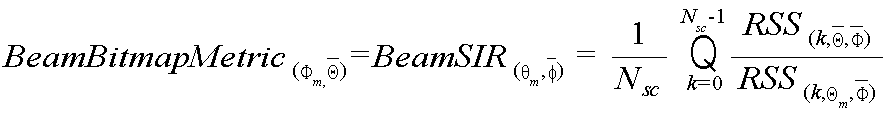
하기 수학식 5는 빔 SIR을 이용하여 빔 비트맵 생성을 위한 매트릭을 계산하는 방식을 나타낸다.Equation (5) represents a method of calculating a matrix for beam bitmap generation using beam SIR.
여기서, ![]()
![]()
![]()
![]()
![]()
![]()
![]()
![]()
![]()
![]()
![]()
![]()
단말은 수학식 4 및 5와 같은 방식으로, 빔 비트맵 생성을 위한 매트릭을 계산한 후, 하기 수학식 6과 같이 빔 비트맵을 생성할 수 있다.The terminal may generate a beam bitmap as shown in Equation (6) after calculating a matrix for beam bitmap generation in the same manner as Equations (4) and (5).


여기서, 
즉, 단말은 최적 수신 안테나 및 빔과 선택되지 않은 송신 안테나의 빔들 사이의 빔 채널 상관관계 혹은 SIR을 기반으로, 빔 비트맵을 생성할 수 있다. 예를 들어, 단말의 최적의 빔 셋이 수신 안테나 #0의 빔 #6, 송신 안테나 #0의 빔 #3인 경우, 도 5에 도시된 바와 같이, 단말은 최적 수신 안테나 #0 및 빔 #6과 선택되지 않은 송신 안테나 #1의 빔들 #1-#5 사이의 신호 수신 세기(RSS)를 계산하고, 도 6에 도시된 바와 같이, 최적 수신 안테나 #0 및 빔 #6에 대한 송신 안테나 #1의 빔들 #1-#5의 신호 간섭 비율(SIR)을 계산한 후, 계산된 간섭 비율을 이용하여 빔 비트맵을 생성할 수 있다. 여기서 신호 간섭 비율은 최적 빔 셋의 채널 품질(예: RSS, -46dBm)과 최적 수신 안테나 #0 및 빔 #6에 대한 송신 안테나 #1의 빔들 #1-#5 각각의 채널 품질(예: RSS, -49dBm, -48dBm, -56dBm, -57dBm, -57dBm)의 차이 값(3dB, 2dB, 10dB, 11dB, 11dB)으로 결정될 수 있다. 여기서, "-"는 #0을 인덱스로 하는 빔이 존재하지 않는 것을 의미한다. 또한, 빔 비트맵은 신호 간섭 비율이 빔 비트맵에 대한 임계값보다 크거나 같은지 여부에 따라 결정될 수 있다. 예컨대, 도 6은 빔 비트맵에 대한 임계값이 10dB인 경우에 대한 빔 비트맵을 나타낸 것으로서, 수신 안테나 #0 및 빔 #6에 대한 송신 안테나 #1의 빔 #1의 신호 간섭 비율은 3dB로 임계값 10dB보다 작기 때문에 빔 비트맵의 값이 0으로 설정되고, 수신 안테나 #0 및 빔 #6에 대한 송신 안테나 #1의 빔 #4의 신호 간섭 비율은 11dB로 임계값 10dB보다 크기 때문에 빔 비트맵의 값이 1로 설정될 수 있다. 이때, 기지국은 단말이 수신 안테나 #0 및 빔 #6을 통해 기지국의 송신 안테나 #0의 빔 #3으로부터 신호를 수신하는 상황에서, 빔 비트맵의 값이 1인 송신 안테나 및 빔으로부터의 간섭 량이 크고, 빔 비트맵의 값이 0인 송신 안테나 및 빔으로부터 간섭 량이 적다고 판단하여, 빔 비트맵 값이 0인 송신 안테나 및 빔을 통해 다른 단말로 서비스를 제공하도록 스케줄링을 수행할 수 있다. That is, the terminal may generate a beam bitmap based on the beam-channel correlation or the SIR between the optimal receive antenna and the beams of the non-selected transmit antenna. For example, when the optimal beam set of the terminal is the
또한, 단말은 SU-MIMO를 지원하기 위해, 다수의 스트림에 대한 최적 빔 셋을 계산하고, 스트림 별 최적 빔 셋 각각에 대한 PMI를 결정할 수 있다. 기지국의 송신 안테나가 NTX, 전송 스트림 수가 Nstream, 단말의 수신 안테나 수가 NRX라고 가정할 때, SU-MIMO를 위해 필요한 PMI 및 선호 송신 안테나 및 빔, 선호 수신 안테나 및 빔 조합의 계산은 하기 수학식 7과 같다.Also, in order to support SU-MIMO, the UE can calculate an optimal beam set for a plurality of streams and determine a PMI for each stream-optimized beam set. Assuming that the transmission antenna of the base station is N TX , the number of transport streams is N stream , and the number of reception antennas of the UE is N RX , calculation of the PMI and the preferred transmission antenna and beam, preferred reception antenna and beam combination required for SU- (7).


여기서, P(p)는 [Nt RF×Nstream]크기를 갖는 P번째 프리코딩 행렬을 의미한다.Here, P (p) denotes a Pth precoding matrix having a size of [ Nt RF x N stream ].
단말은 911단계에서 빔 비트맵 및/혹은 PMI를 피드백한 이후, 913단계에서 기지국으로부터 스케줄링 정보를 수신할 수 있다.The UE may receive the beam bitmap and / or the PMI in
이후, 단말은 본 발명의 실시 예에 따른 절차를 종료한다.
Thereafter, the terminal terminates the procedure according to the embodiment of the present invention.
도 10은 본 발명의 실시 예에 따른 기지국에서 스케줄링 절차를 도시하고 있다.FIG. 10 shows a scheduling procedure in a base station according to an embodiment of the present invention.
도 10을 참조하면, 기지국은 1001단계에서 서비스 영역 내 적어도 하나의 단말과 빔 그루핑을 위한 협상을 수행하여, 빔 그룹을 생성한다. 예컨대, 기지국과 단말은 미리 설정된 주기 혹은 특정 이벤트 발생 시점에 다수의 빔 각각에 대한 채널 특성을 기반으로 빔 그루핑을 수행할 수 있다. 예를 들어, 기지국과 단말은 빔 별 수신 신호 세기, 채널 상관 관계, 및 직교성 등과 같은 채널 특성을 기반으로 자신이 지원하는 빔들을 다수의 빔 그룹으로 그루핑하고, 빔 그룹에 대한 정보를 교환할 수 있다. Referring to FIG. 10, in
이후, 기지국은 1003단계에서 적어도 하나의 단말로 빔 비트맵에 대한 임계값을 방송한다. 여기서, 빔 비트맵은 단말에서 선택된 최적 수신 안테나 및 빔에 대해 기지국의 송신 안테나 및 빔들이 미치는 간섭 정보로서, 비트맵 형식으로 구성될 수 있다. 또한, 빔 비트맵에 대한 임계값은, 단말에서 빔 비트맵을 생성 혹은 구성하기 위해 이용되는 정보로서, 시스템의 부하, 단말들의 격리(isolation) 분포에 대한 정보, 혹은 스케줄링 정책에 따라 결정될 수 있다. 빔 비트맵에 대한 임계값은 고정된 값일 수도 있고, 가변적인 값일 수도 있다. 기지국은 빔 비트맵에 대한 임계값이 변경될 때마다 변경된 임계값을 방송할 수도 있고, 빔 비트맵에 대한 임계값을 변경하는 규칙을 방송하여, 단말에서 변경되는 임계값을 직접 계산하도록 할 수 있다. 추가적으로, 기지국은 빔 비트맵에 대한 단위 정보를 방송할 수 있다. 예를 들어, 기지국은 빔 비트맵에 하나의 빔 그룹에 포함된 적어도 하나의 빔들에 대한 정보가 포함되어야할지, 혹은 다수의 빔 그룹 각각에 대한 정보가 포함되어야 할지 나타내는 정보를 브로드캐스팅할 수 있다.In
이후, 기지국은 1005단계에서 적어도 하나의 단말로부터 선택된 선호 송신 안테나 및 빔에 대한 정보를 수신하고, 1007단계에서 적어도 하나의 단말로부터 비트맵 및/혹은 PMI 정보를 수신한다. 여기서, 선호 송신 안테나 및 빔은 단말에서 선택된 최적 빔 셋에 포함된 기지국의 송신 안테나 및 빔을 의미한다.In
기지국은 1009단계에서 단말로 할당 가능한 스케줄링 자원이 존재하는지 여부를 검사한다. 단말로 할당 가능한 스케줄링 자원이 존재할 시, 기지국은 1011단계로 진행하여 적어도 하나의 단말로부터 수신된 정보를 기반으로 아날로그 빔포밍을 위한 유효 CQI 및 하이브리드 빔포밍을 위한 유효 CQI를 계산한다. 예컨대, 적어도 하나의 단말로부터 빔 비트맵이 수신된 경우, 기지국은 랭크(rank)가 추가될 때마다 하기 수학식 8과 같이 유효 CQI를 계산할 수 있다.In
![]()
![]()
여기서, eCQI(k,r)은 사용자 k의 총 랭크 수 r에 대한 유효 CQI를 의미한다. CQI(k)는 사용자 k에 대한 CQI를 의미하고, BemaBitmapthreshold는 빔 비트맵에 대한 임계값을 의미하고, offset(k,r)은 사용자 k와 랭크 r에 대한 스케줄러의 조절 오프셋 값을 의미한다. Here, eCQI (k, r) denotes a valid CQI for the total rank r of user k. CQI (k) denotes a CQI for a user k, BemaBitmap threshold denotes a threshold value for a beam bitmap, and offset (k, r) denotes an adjustment offset value of a scheduler for a user k and a rank r .
일 예로, 아날로그 빔포밍을 위한 유효 CQI와 하이브리드 빔포밍을 위한 유효 CQI를 계산하는 방식에 대해 설명한다.As an example, a description will be given of a method of calculating a valid CQI for analog beamforming and a valid CQI for hybrid beamforming.
먼저, 할당 가능한 랭크 수가 r개이고 사용자 k의 유효 CQI를 계산할 때, 비트맵이 1인 빔이 선택된 경우에 사용자 k에 대한 아날로그 빔포밍의 유효 CQI는 하기 수학식 9와 같이 계산할 수 있다. 반면, 할당 가능한 랭크 수가 r개이고 사용자 k의 유효 CQI를 계산할 때, 비트맵이 0인 빔이 선택된 경우에 사용자 k에 대한 아날로그 빔포밍의 유효 CQI는 하기 수학식 10과 같이 계산할 수 있다.First, when calculating the effective CQI of the user k and r is the number of assignable ranks, the effective CQI of the analog beamforming for the user k can be calculated by Equation (9) when the beam having the bitmap of 1 is selected. On the other hand, when calculating the effective CQI of the user k and r being the number of assignable ranks, if the beam having the bitmap of 0 is selected, the effective CQI of the analog beamforming for the user k can be calculated as shown in Equation (10).


수학식 9 및 10에서 CQI(k)는 S(k)/(I(k)+n(k))이고, S(k)는 사용자 k에 대한 신호 세기를 의미하며, I(k)는 사용자 k에 대한 간섭 세기를 의미하고, n(k)는 사용자 k의 잡음 전력을 의미한다.In Equations (9) and (10), CQI (k) is the signal strength for user k, I (k) (k) denotes the noise power of the user k, and n (k) denotes the noise power of the user k.
다른 예로, 적어도 하나의 단말로부터 PMI가 수신된 경우, 기지국은 랭크(rank)가 추가될 때마다 하기 수학식 11과 같이 하이브리드 빔포밍을 위한 유효 CQI를 계산할 수 있다.As another example, when a PMI is received from at least one terminal, the base station can calculate a valid CQI for hybrid beamforming as shown in Equation (11) whenever a rank is added.
![]()
![]()

![]()
![]()
Pk는 단말 k가 보고한 PMI를 의미하고, wk는 단말 k의 코드북 기반 다중 사용자 가중치를 의미한다.P k denotes the PMI reported by the terminal k, and w k denotes the codebook-based multi-user weight of the terminal k.
이후, 기지국은 1013단계에서 계산된 각각의 유효 CQI를 이용하여 빔포밍 방식별 효율을 나타내는 sumPF를 계산하고, 1015단계에서 빔포밍 방식별 sumPF를 비교하여 스케줄링 단말을 결정할 수 있다. 예컨대, 기지국은 하기 수학식 12와 같이, 유효 CQI를 이용하여 sumPF를 계산할 수 있다.Then, the base station calculates sumPF representing the efficiency of each beamforming scheme using each effective CQI calculated in

즉, 기지국은 아날로그 빔포밍을 위한 유효 CQI를 이용하여 아날로그 빔포밍에 대한 SumPF를 계산하고, 하이브리드 빔포밍을 위한 유효 CQI를 이용하여 하이브리드 빔포밍에 대한 SumPF를 계산할 수 있다. 기지국은 계산된 두 SumPF의 값을 비교하여 스케줄링을 수행할 수 있다. 예컨대, 하이브리드 빔포밍에 대한 SumPF가 아날로그 빔포밍에 대한 SumPF보다 크거나 같은 경우, 하이브리드 빔포밍 방식으로 사용자 단말에 스케줄링을 수행하고, 하이브리드 빔포밍에 대한 SumPF가 아날로그 빔포밍에 대한 SumPF보다 작을 경우, 아날로그 빔포밍 방식으로 사용자 단말에 대한 스케줄링을 수행할 수 있다.That is, the base station calculates SumPF for analog beamforming using the valid CQI for analog beamforming, and calculates SumPF for hybrid beamforming using the valid CQI for hybrid beamforming. The base station can perform scheduling by comparing the calculated values of two SumPFs. For example, when SumPF for hybrid beamforming is equal to or greater than SumPF for analog beamforming, scheduling is performed to the user terminal using a hybrid beamforming scheme, and when SumPF for hybrid beamforming is smaller than SumPF for analog beamforming , And can perform scheduling for a user terminal using an analog beamforming method.
이후, 기지국은 1017단계에서 결정된 단말로 스케줄링 정보를 전송하고, 본 발명의 실시 예에 따른 절차를 종료한다.
Thereafter, the BS transmits the scheduling information to the UE determined in step 1017 and terminates the procedure according to the embodiment of the present invention.
도 11은 본 발명의 실시 예에 따른 단말의 블럭 구성을 도시하고 있다.FIG. 11 shows a block configuration of a terminal according to an embodiment of the present invention.
도 11을 참조하면, 단말은 빔 별 채널 정보 획득기(1100), 최적 빔 셋 결정기(1110), 빔 매트릭 계산기(1120), 빔 비트맵 생성기(1130), PMI 결정기(1140) 및 피드백 정보 생성기(1150)를 포함하여 구성될 수 있다. 여기서는 본 발명의 실시 예들에서 설명한 단말의 기능에 따라 각 구성 요소들을 구분하여 도시하였으나, 도시된 각 구성요소들은 하나 혹은 하나 이상의 다른 구성 요소로 구현될 수도 있다. 예를 들어, 도 11에 도시된 구성 요소들은 하나의 제어부로 구성될 수 있다.11, the UE includes a beam-by-beam
빔 별 채널 정보 획득기(1100)는 기지국의 안테나에 의해 형성 가능한 다수의 송신 빔들과 단말의 안테나에 의해 형성 가능한 다수의 수신 빔들 사이의 채널 정보를 획득하고, 획득된 빔별 채널 정보를 최적 빔 셋 결정기(1110)와 빔 매트릭 계산기(1120)로 제공한다. The beam-specific
최적 빔 셋 결정기(1110)는 빔 별 채널 정보를 기반으로 선호하는 최적 송신 안테나 및 빔과 수신 안테나 및 빔을 결정한다. 예를 들어, 최적 빔 셋 결정기(1110)는 가장 큰 CQI 값을 갖는 기지국의 송신 안테나 및 빔과 단말의 수신 안테나 및 빔을 선택하고, 선택된 빔 셋을 최적 빔 셋으로 결정한다. 최적 빔 셋 결정기(1110)는 선택된 최적 빔 셋에 대한 정보를 PMI 결정기(1140)와 피드백 정보 생성기(1150)로 제공한다. 또한, 최적 빔 셋 결정기(1110)는 빔 별 채널 정보를 피드백 정보 생성기(1150)와 PMI 결정기(1140)로 제공할 수 있다. 예를 들어, 최적 빔 셋 결정기(1110)는 최적 빔 셋에 대한 CQI를 피드백 정보 생성기(1150)로 제공할 수 있다.The optimal beam set
빔 매트릭 계산기(1120)는 기지국의 송신 안테나 및 빔과 단말의 수신 안테나 및 빔으로 다양한 빔 조합을 생성하고, 생성된 빔 조합들에 대한 빔 매트릭을 계산한다. 여기서, 빔 매트릭은 해당 빔 조합(예: i번째 송신 안테나의 n번째 송신 빔과 j번째 수신 안테나의 m번째 수신 빔)에 대한 용량(capacity), SINR, SIR, 혹은 RSS를 포함하는 의미이다.The beam
빔 비트맵 생성기(1130)는 빔 매트릭 계산기(1120)로부터 빔 조합들에 대한 빔 매트릭 정보를 수신하고, 수신된 정보와 기지국으로부터 방송된 빔 비트맵에 대한 임계값을 기반으로 빔 비트맵을 생성한다. 예컨대, 빔 비트맵 생성기(1130)는 단말이 기지국으로부터 최적 빔 셋을 통해 서비스를 받는 상황에서, 기지국이 특정 송신 안테나 및 빔을 통해 다른 단말로 서비스를 지원하는 경우, 특정 송신 안테나 및 빔에 의해 자신이 받을 수 있는 간섭 량을 나타내는 빔 비트맵을 생성할 수 있다. 빔 비트맵 생성기(1130)는 생성된 빔 비트맵을 피드백 정보 생성기(1150)로 제공한다.The
PMI 결정기(1140)는 최적 빔 셋 결정기(1110)로부터 제공되는 빔 별 채널 정보와 최적 빔 셋 정보를 기반으로 최적 빔 셋에 대한 PMI를 결정할 수 있다.The
피드백 정보 생성기(1150)는 최적 빔 셋 결정기(1110)로부터 제공된 최적 빔 셋과 최적 빔 셋에 대한 CQI 정보를 기지국으로 피드백하기 위한 정보로 가공하여, 기지국으로 피드백하기 위한 기능을 제어 및 처리한다. 또한, 피드백 정보 생성기(1150)는 빔 비트맵 생성기(1130)로부터 제공되는 빔 비트맵 및 PMI 결정기(1140)로부터 제공되는 PMI를 기지국으로 피드백하기 위한 기능을 제어 및 처리한다.The
추가적으로, 도면에는 도시되지 않았으나, 단말은 송수신기를 포함할 수 있다. 송수신기는 다수 개의 안테나를 포함하여 구성됨으로써, 피드백 정보 생성기(1150)로부터 생성된 피드백 정보들을 기지국으로 피드백 처리할 수 있다. 또한, 송수신기는 다수 개의 안테나를 통해 기지국과의 신호를 송수신하는 기능을 수행한다. 여기서, 안테나는 특정 방향으로의 빔 형성이 가능한 빔 안테나 및/혹은 배열 안테나를 포함하는 의미이다.
Additionally, although not shown in the drawings, the terminal may include a transceiver. The transceiver includes a plurality of antennas, thereby feedback processing the feedback information generated from the
도 12는 본 발명의 실시 예에 따른 기지국의 블럭 구성을 도시하고 있다.FIG. 12 shows a block configuration of a base station according to an embodiment of the present invention.
도 12를 참조하면, 기지국은 피드백 정보 획득기(1200), 스케줄러(1210), 유효 CQI 계산기(1220), 빔 비트맵 임계값 결정기(1230), 및 하향링크 제어 및 데이터 할당기(1240)를 포함하여 구성될 수 있다. 여기서는 본 발명의 실시 예들에서 설명한 기지국의 기능에 따라 각 구성 요소들을 구분하여 도시하였으나, 도시된 각 구성요소들은 하나 혹은 하나 이상의 다른 구성 요소로 구현될 수도 있다. 예를 들어, 도 12에 도시된 구성 요소들은 하나의 제어부로 구성될 수 있다.12, the base station includes a
피드백 정보 획득기(1200)는 단말로부터 수신되는 신호들로부터 피드백 정보를 획득할 수 있다. 예를 들어, 피드백 정보 획득기(1200)는 단말로부터 피드백되는 최적 빔 셋에 대한 정보 및 최적 빔 셋에 대한 채널 정보(예: CQI)를 획득할 수 있고, 단말로부터 수신되는 빔 비트맵 및/혹은 PMI 정보를 획득할 수 있다. 피드백 정보 획득기(1220)는 획득된 피드백 정보들을 스케줄러(1210)로 제공한다.The
스케줄러(1210)는 단말의 스케줄링을 위한 전반적인 기능을 제어 및 처리한다. 예를 들어, 스케줄러(1210)는 단말로부터의 피드백 정보를 유효 CQI 계산기(1220)로 제공하고, 유효 CQI 계산기(1220)로부터 아날로그 빔포밍을 위한 유효 CQI 및 하이브리드 빔포밍을 위한 유효 CQI를 획득하고, 아날로그 빔포밍을 위한 유효 CQI와 하이브리드 빔포밍을 위한 유효 CQI 각각에 대한 SumPF를 계산하고, 계산된 각각의 SumPF를 비교하여 단말에 대한 스케줄링을 수행한다. 스케줄러(120)는 상술한 도 2 내지 도 10에서 나타낸 기지국의 전반적인 동작들을 수행하기 위한 기능을 제어 및 처리한다.The
유효 CQI 계산기(1220)는 스케줄러(1210)로부터 피드백 정보를 수신하고, 아날로그 빔포밍을 위한 유효 CQI 및 하이브리드 빔포밍을 위한 유효 CQI를 계산하여 스케줄러(1210)로 제공한다. The
빔 비트맵 임계값 결정기(1230)는 빔 비트맵에 대한 임계값을 결정하낟. 빔 비트맵 임계값 결정기(1230)는 시스템의 부하, 단말들의 격리 분포에 대한 정보, 혹은 스케줄링 정책에 따라 빔 비트맵에 대한 임계값을 결정할 수 있다. 빔 비트맵에 대한 임계값은 고정된 값일 수도 있고, 가변적인 값일 수도 있다. 추가적으로, 빔 비트맵 임계값 결정기(1230)는 빔 비트맵에 대한 단위를 결정할 수 있다. The beam
하향링크 제어 및 데이터 할당기(1240)는 스케줄러(1240)의 스케줄링 결과를 기반으로 각 단말로 자원을 할당하고, 하향링크 제어 정보 및 데이터를 전송하기 위한 기능을 제어 및 처리한다.The downlink control and
추가적으로, 도면에는 도시되지 않았으나, 기지국은 송수신기를 포함할 수 있다. 송수신기는 다수 개의 안테나를 포함하여 구성됨으로써, 단말로부터 피드백되는 정보들을 수신 처리할 수 있다. 또한, 송수신기는 다수 개의 안테나를 통해 단말과의 신호를 송수신하는 기능을 수행한다. 여기서, 안테나는 특정 방향으로의 빔 형성이 가능한 빔 안테나 및/혹은 배열 안테나를 포함하는 의미이다.
Additionally, although not shown in the drawings, the base station may include a transceiver. The transceiver includes a plurality of antennas, thereby receiving and processing information fed back from the terminal. The transceiver also transmits and receives signals to and from the terminal through a plurality of antennas. Here, the antenna means a beam antenna and / or an array antenna capable of forming a beam in a specific direction.
이상과 같이 본 발명은 비록 한정된 실시 예와 도면에 의해 설명되었으나 본 발명은 상술한 실시 예에 한정되는 것은 아니며, 본 발명이 속하는 분야에서 통상의 지식을 가진 자라면 이러한 기재로부터 다양한 수정 및 변형이 가능하다. While the present invention has been particularly shown and described with reference to exemplary embodiments thereof, it is to be clearly understood that the same is by way of illustration and example only and is not to be taken by way of limitation, It is possible.
본 발명의 실시 예에 따른 동작들은 단일의 제어부에 의해 그 동작이 구현될 수 있을 것이다. 이러한 경우 다양한 컴퓨터로 구현되는 동작을 수행하기 위한 프로그램 명령이 컴퓨터 판독 가능 매체에 기록될 수 있다. 상기 컴퓨터 판단 가능 매체는 프로그램 명령, 데이터 파일, 데이터 구조 등을 단독으로 또는 조합하여 포함할 수 있다. 상기 프로그램 명령은 본 발명을 위하여 특별히 설계되고 구성된 것들이거나 당업자에게 공지되어 사용 가능한 것일 수도 있다. 컴퓨터 판독 가능 기록 매체의 예에는 하드 디스크, 플로피 디스크 및 자기 테이프와 같은 자기 매체, CD-ROM이나 DVD와 같은 광기록 매체, 플롭티컬 디스크(floptical disk)와 같은 자기-광 매체 및 롬(ROM), 램(RAM), 플래시 메모리 등과 같은 프로그램 명령을 저장하고 수행하도록 특별히 구성된 하드웨어 장치가 포함된다. 프로그램 명령의 예에는 컴파일러에 의해 만들어지는 것과 같은 기계어 코드뿐만 아니라 인터프리터 등을 사용해서 컴퓨터에 의해서 실행될 수 있는 고급 언어 코드를 포함한다. 본 발명에서 설명된 기지국 또는 릴레이의 전부 또는 일부가 컴퓨터 프로그램으로 구현된 경우 상기 컴퓨터 프로그램을 저장한 컴퓨터 판독 가능 기록 매체도 본 발명에 포함된다. 그러므로 본 발명의 범위는 설명된 실시예에 국한되어 정해져서는 아니되며, 후술하는 특허청구범위뿐만 아니라 이 특허청구범위와 균등한 것들에 의해 정해져야 할 것이다.Operations according to embodiments of the present invention may be implemented by a single controller. In this case, program instructions for performing various computer-implemented operations may be recorded on a computer-readable medium. The computer-determinable medium may include program instructions, data files, data structures, etc., alone or in combination. The program instructions may be those specially designed and constructed for the present invention or may be available to those skilled in the art. Examples of computer-readable media include magnetic media such as hard disks, floppy disks and magnetic tape, optical recording media such as CD-ROMs or DVDs, magneto-optical media such as floppy disks and ROMs, , Random access memory (RAM), flash memory, and the like. Examples of program instructions include machine language code such as those produced by a compiler, as well as high-level language code that can be executed by a computer using an interpreter or the like. When all or a part of the base station or relay described in the present invention is implemented as a computer program, the computer readable recording medium storing the computer program is also included in the present invention. The scope of the present invention should, therefore, be determined not only by the details of the embodiments described, but also by the appended claims and their equivalents.
Claims (24)
기지국의 다수의 송신 빔과 단말의 다수의 수신 빔 사이의 채널을 기반으로 송신 빔과 수신 빔으로 구성된 적어도 하나의 선호 빔 셋을 결정하는 과정과,
상기 선호 빔 셋에 대한 정보를 상기 기지국으로 전송하는 과정과,
상기 선호 빔 셋에 포함된 선호 수신 빔을 기반으로 상기 기지국의 적어도 하나의 송신 빔이 상기 단말에 미치는 간섭을 나타내는 정보를 생성하는 과정과,
상기 생성된 간섭 정보를 상기 기지국으로 전송하는 과정을 포함하는 방법.
A method of a terminal in a wireless communication system supporting multiple input multiple output,
Determining at least one preferred beam set composed of a transmission beam and a reception beam based on a channel between a plurality of transmission beams of a base station and a plurality of reception beams of a terminal,
Transmitting the information on the preferred beam set to the base station;
Generating information indicating interference of at least one transmission beam of the base station to the terminal based on a preferred reception beam included in the preferred beam set;
And transmitting the generated interference information to the base station.
상기 선호 빔 셋에 대한 정보는, 송신 안테나 인덱스와 송신 빔 인덱스로 구성되는 선호 송신 빔 정보와, 수신 안테나 인덱스와 수신 빔 인덱스로 구성되는 선호 수신 빔 정보 중 적어도 하나를 포함하는 방법.
The method according to claim 1,
Wherein the information on the preferred beam set includes at least one of the preferred transmission beam information including a transmission antenna index and a transmission beam index and the preferred reception beam information including a reception antenna index and a reception beam index.
상기 선호 빔 셋에 포함된 선호 수신 빔을 기반으로 상기 기지국의 적어도 하나의 송신 빔이 상기 단말에 미치는 간섭을 나타내는 정보를 생성하는 과정은,
상기 기지국과의 협상을 통해 상기 기지국의 다수의 송신 빔과 단말의 다수의 수신 빔을 다수 개의 그룹으로 구분하는 과정과,
상기 기지국의 송신 빔들로 구성된 빔 그룹 중에서 상기 선호 빔 셋에 포함된 선호 송신 빔이 속한 그룹을 제외한, 나머지 송신 빔 그룹이 상기 선호 빔 셋에 포함된 선호 수신 빔에 미치는 간섭을 나타내는 비트맵을 생성하는 과정을 포함하는 방법.
The method according to claim 1,
Wherein the step of generating information indicating interference of at least one transmission beam of the base station to the terminal based on the preferred reception beam included in the preferred beam set comprises:
Dividing a plurality of transmission beams of the base station and a plurality of reception beams of the terminal into a plurality of groups through negotiation with the base station;
Generating a bitmap indicating interference of the remaining transmission beam groups except the group to which the preferred transmission beam included in the preferred beam set belongs, on the preferred reception beam included in the preferred beam set among the beam groups constituted of the transmission beams of the base station ≪ / RTI >
상기 비트맵을 생성하는 과정은,
상기 선호 수신 빔과 선호 송신 빔 사이의 채널 추정 값과, 상기 선호 수신 빔과 상기 나머지 송신 빔 그룹 내 송신 빔 사이의 채널 추정 값의 차이값을 계산하는 과정과,
상기 차이 값을 상기 기지국으로부터 수신된 임계값과 비교하는 과정과,
상기 임계값보다 크거나 같은 차이 값을 가지는 송신 빔이 상기 선호 수신 빔에 대해 간섭을 미침을 나타내는 비트맵을 생성하는 과정을 포함하며,
상기 채널 추정 값은, 채널 품질 지시 정보, 신호 수신 세기, 신호대 간섭 잡음의 비, 신호대 간섭비 중 적어도 하나를 포함하는 방법.
The method of claim 3,
Wherein the generating the bitmap comprises:
Calculating a difference between a channel estimation value between the preferred reception beam and the preferred transmission beam and a channel estimation value between the preferred reception beam and the remaining transmission beam group;
Comparing the difference with a threshold value received from the base station;
And generating a bitmap indicating that the transmission beam having a difference value equal to or greater than the threshold value is in interference with the preferred reception beam,
Wherein the channel estimate value comprises at least one of channel quality indication information, signal reception strength, signal to interference noise ratio, and signal to interference ratio.
상기 비트맵 전송 시, 상기 선호 빔 셋에 대한 PMI(Precoding Matrix Indicator)를 전송하는 과정을 더 포함하는 방법.
The method of claim 3,
And transmitting a PMI (Precoding Matrix Indicator) for the preferred beam set when transmitting the bitmap.
상기 적어도 하나의 선호 빔 셋을 결정하는 과정은,
상기 기지국의 다수의 송신 빔과 단말의 다수의 수신 빔 사이의 채널을 기반으로 하나의 송신 빔과 하나의 수신 빔으로 구성된 제 1 선호 빔 셋을 결정하는 과정과,
상기 최적 빔 셋이 속한 빔 그룹을 제외한 나머지 빔 그룹을 대상으로 제 2 선호 빔 셋을 결정하는 과정을 포함하는 방법.
The method according to claim 1,
Wherein the determining of the at least one preferred beam set comprises:
Determining a first preferred beam set including one transmission beam and one reception beam based on a channel between a plurality of transmission beams of the base station and a plurality of reception beams of the terminal;
And determining a second preferred beam set for a remaining beam group excluding a beam group to which the optimum beam set belongs.
단말로부터 기지국의 다수의 송신 빔과 단말의 다수의 수신 빔 사이의 채널을 기반으로 선택된 적어도 하나의 선호 빔 셋에 대한 정보를 수신하는 과정과,
상기 단말로부터 상기 기지국의 적어도 하나의 송신 빔이 상기 단말에 미치는 간섭을 나타내는 정보를 수신하는 과정과,
상기 수신된 간섭 정보와 상기 선호 빔 셋 정보를 기반으로 상기 단말에 대한 스케줄링을 수행하는 과정을 포함하는 방법.
A method of a base station in a wireless communication system supporting multiple input multiple output,
Receiving information on at least one preferred beam set selected based on a channel between a plurality of transmission beams of the base station and a plurality of reception beams of the terminal from the terminal,
Receiving information indicating interference caused by at least one transmission beam of the base station from the terminal to the terminal;
And performing scheduling for the UE based on the received interference information and the preferred beam set information.
상기 선호 빔 셋에 대한 정보는, 송신 안테나 인덱스와 송신 빔 인덱스로 구성되는 선호 송신 빔 정보와, 수신 안테나 인덱스와 수신 빔 인덱스로 구성되는 선호 수신 빔 정보 중 적어도 하나를 포함하는 방법.
8. The method of claim 7,
Wherein the information on the preferred beam set includes at least one of the preferred transmission beam information including a transmission antenna index and a transmission beam index and the preferred reception beam information including a reception antenna index and a reception beam index.
상기 단말과의 협상을 통해 상기 기지국의 다수의 송신 빔과 단말의 다수의 수신 빔을 다수 개의 그룹으로 구분하는 과정과,
상기 간섭을 나타내는 정보를 생성하기 위한 임계값을 방송하는 과정을 더 포함하며,
상기 임계값은 시스템 부하, 단말의 격리 분포 정보, 스케줄링 정책 중 적어도 하나를 기반으로 결정되는 방법.
8. The method of claim 7,
Dividing a plurality of transmission beams of the base station and a plurality of reception beams of the terminal into a plurality of groups through negotiation with the terminal;
Further comprising the step of broadcasting a threshold value for generating information indicating the interference,
Wherein the threshold is determined based on at least one of a system load, isolation distribution information of a terminal, and a scheduling policy.
상기 간섭을 나타내는 정보는, 상기 기지국의 송신 빔들로 구성된 빔 그룹 중에서 선호 송신 빔이 속한 그룹을 제외한, 나머지 송신 빔 그룹이 선호 수신 빔에 미치는 간섭을 나타내는 비트맵을 포함하는 방법.
10. The method of claim 9,
Wherein the information indicating the interference includes a bitmap indicating an interference of the remaining transmission beam group on the preferred reception beam excluding a group to which the preferred transmission beam belongs among the beam groups constituted of the transmission beams of the base station.
상기 비트맵 수신 시, 상기 선호 빔 셋에 대한 PMI(Precoding Matrix Indicator)를 수신하는 과정을 더 포함하는 방법.
10. The method of claim 9,
And receiving a PMI (Precoding Matrix Indicator) for the preferred beam set upon receiving the bitmap.
상기 수신된 간섭 정보와 상기 선호 빔 셋 정보를 기반으로 상기 단말에 대한 스케줄링을 수행하는 과정은,
상기 수신된 간섭 정보를 기반으로 아날로그 빔포밍 방식에 대한 제 1 유효 채널 정보와 하이브리드 빔포밍 방식에 대한 제 2 유효 채널 정보를 계산하는 과정과,
상기 계산된 제 1 유효 채널 정보와 제 2 유효 채널 정보 각각에 대한 효율을 계산하는 과정과,
상기 계산된 효율을 기반으로 상기 단말에 대한 스케줄링을 수행하는 과정을 포함하는 방법.
8. The method of claim 7,
Wherein the step of performing scheduling for the UE based on the received interference information and the preferred beam set information comprises:
Calculating first effective channel information for an analog beamforming scheme and second valid channel information for a hybrid beamforming scheme based on the received interference information,
Calculating efficiency for each of the calculated first effective channel information and second calculated channel information;
And performing scheduling for the UE based on the calculated efficiency.
기지국과 신호를 송수신하는 통신부와,
상기 기지국의 다수의 송신 빔과 단말의 다수의 수신 빔 사이의 채널을 기반으로 송신 빔과 수신 빔으로 구성된 적어도 하나의 선호 빔 셋을 결정하고, 상기 선호 빔 셋에 대한 정보를 상기 기지국으로 전송하고, 상기 선호 빔 셋에 포함된 선호 수신 빔을 기반으로 상기 기지국의 적어도 하나의 송신 빔이 상기 단말에 미치는 간섭을 나타내는 정보를 생성하고, 상기 생성된 간섭 정보를 상기 기지국으로 전송하기 위한 기능을 제어하는 제어부를 포함하는 장치.
An apparatus of a terminal in a wireless communication system supporting multiple input multiple output,
A communication unit for transmitting and receiving signals to / from the base station,
Determines at least one preferred beam set composed of a transmission beam and a reception beam based on a channel between a plurality of transmission beams of the base station and a plurality of reception beams of the terminal and transmits information on the preferred beam set to the base station , Generating information indicating interference caused by the at least one transmission beam of the base station based on the preferred reception beam included in the preferred beam set, and controlling the function for transmitting the generated interference information to the base station And a control unit for controlling the control unit.
상기 선호 빔 셋에 대한 정보는, 송신 안테나 인덱스와 송신 빔 인덱스로 구성되는 선호 송신 빔 정보와, 수신 안테나 인덱스와 수신 빔 인덱스로 구성되는 선호 수신 빔 정보 중 적어도 하나를 포함하는 장치.
14. The method of claim 13,
Wherein the information on the preferred beam set includes at least one of the preferred transmission beam information including the transmission antenna index and the transmission beam index, and the preferred reception beam information including the reception antenna index and the reception beam index.
상기 제어부는, 상기 기지국과의 협상을 통해 상기 기지국의 다수의 송신 빔과 단말의 다수의 수신 빔을 다수 개의 그룹으로 구분하고, 상기 기지국의 송신 빔들로 구성된 빔 그룹 중에서 상기 선호 빔 셋에 포함된 선호 송신 빔이 속한 그룹을 제외한, 나머지 송신 빔 그룹이 상기 선호 빔 셋에 포함된 선호 수신 빔에 미치는 간섭을 나타내는 비트맵을 생성하는 장치.
14. The method of claim 13,
Wherein the controller divides a plurality of transmission beams of the base station and a plurality of reception beams of the terminal into a plurality of groups through negotiation with the base station and selects one of the beam groups included in the preferred beam set And generates a bitmap indicating the interference of the remaining transmission beam groups except the group to which the preferred transmission beam belongs, on the preferred reception beam included in the preferred beam set.
상기 제어부는, 상기 선호 수신 빔과 선호 송신 빔 사이의 채널 추정 값과, 상기 선호 수신 빔과 상기 나머지 송신 빔 그룹 내 송신 빔 사이의 채널 추정 값의 차이값을 계산하고, 상기 차이 값을 상기 기지국으로부터 수신된 임계값과 비교하고, 상기 임계값보다 크거나 같은 차이 값을 가지는 송신 빔이 상기 선호 수신 빔에 대해 간섭을 미침을 나타내는 비트맵을 생성하며,
상기 채널 추정 값은, 채널 품질 지시 정보, 신호 수신 세기, 신호대 간섭 잡음의 비, 신호대 간섭비 중 적어도 하나를 포함하는 장치.
16. The method of claim 15,
Wherein the controller calculates a difference between a channel estimation value between the preferred reception beam and the preferred transmission beam and a channel estimation value between the preferred reception beam and the remaining transmission beam group transmission beam, And generates a bitmap indicating that a transmission beam having a difference value equal to or greater than the threshold value is experiencing interference with the preferred reception beam,
Wherein the channel estimate value comprises at least one of channel quality indication information, signal reception strength, signal to interference noise ratio, and signal to interference ratio.
상기 제어부는, 상기 비트맵 전송 시, 상기 선호 빔 셋에 대한 PMI(Precoding Matrix Indicator)를 전송하기 위한 기능을 제어하는 장치.
16. The method of claim 15,
Wherein the control unit controls a function of transmitting a PMI (Precoding Matrix Indicator) for the preferred beam set when transmitting the bitmap.
상기 제어부는, 상기 기지국의 다수의 송신 빔과 단말의 다수의 수신 빔 사이의 채널을 기반으로 하나의 송신 빔과 하나의 수신 빔으로 구성된 제 1 선호 빔 셋을 결정하고, 상기 최적 빔 셋이 속한 빔 그룹을 제외한 나머지 빔 그룹을 대상으로 제 2 선호 빔 셋을 결정하여, 상기 적어도 하나의 선호 빔 셋을 결정하는 장치.
14. The method of claim 13,
Wherein the controller determines a first preferred beam set composed of one transmission beam and one reception beam based on a channel between a plurality of transmission beams of the base station and a plurality of reception beams of the terminal, Determining a second preferred beam set for the remaining beam groups excluding the beam group, and determining the at least one preferred beam set.
단말과 신호를 송수신하는 통신부와,
단말로부터 기지국의 다수의 송신 빔과 단말의 다수의 수신 빔 사이의 채널을 기반으로 선택된 적어도 하나의 선호 빔 셋에 대한 정보를 수신하고, 상기 단말로부터 상기 기지국의 적어도 하나의 송신 빔이 상기 단말에 미치는 간섭을 나타내는 정보를 수신하고, 상기 수신된 간섭 정보와 상기 선호 빔 셋 정보를 기반으로 상기 단말에 대한 스케줄링을 수행하기 위한 기능을 제어하는 제어부를 포함하는 장치.
An apparatus of a base station in a wireless communication system supporting multiple input multiple output,
A communication unit for transmitting and receiving signals to and from the terminal,
The method comprising the steps of: receiving information on at least one preferred beam set selected based on a channel between a plurality of transmission beams of a base station and a plurality of reception beams of a terminal from at least one terminal and transmitting at least one transmission beam of the base station from the terminal to the terminal And a controller for controlling a function of performing scheduling for the UE based on the received interference information and the preferred beam set information.
상기 선호 빔 셋에 대한 정보는, 송신 안테나 인덱스와 송신 빔 인덱스로 구성되는 선호 송신 빔 정보와, 수신 안테나 인덱스와 수신 빔 인덱스로 구성되는 선호 수신 빔 정보 중 적어도 하나를 포함하는 장치.
20. The method of claim 19,
Wherein the information on the preferred beam set includes at least one of the preferred transmission beam information including the transmission antenna index and the transmission beam index, and the preferred reception beam information including the reception antenna index and the reception beam index.
상기 제어부는, 상기 단말과의 협상을 통해 상기 기지국의 다수의 송신 빔과 단말의 다수의 수신 빔을 다수 개의 그룹으로 구분하고, 상기 간섭을 나타내는 정보를 생성하기 위한 임계값을 방송하기 위한 기능을 제어하며,
상기 임계값은 시스템 부하, 단말의 격리 분포 정보, 스케줄링 정책 중 적어도 하나를 기반으로 결정되는 장치.
20. The method of claim 19,
The controller divides a plurality of transmission beams of the base station and a plurality of reception beams of the terminal into a plurality of groups through negotiation with the terminal and broadcasts a threshold value for generating information indicating the interference Control,
Wherein the threshold is determined based on at least one of a system load, isolation distribution information of a terminal, and a scheduling policy.
상기 간섭을 나타내는 정보는, 상기 기지국의 송신 빔들로 구성된 빔 그룹 중에서 선호 송신 빔이 속한 그룹을 제외한, 나머지 송신 빔 그룹이 선호 수신 빔에 미치는 간섭을 나타내는 비트맵을 포함하는 장치.
22. The method of claim 21,
Wherein the information indicating the interference includes a bitmap indicating interference of the remaining transmission beam groups on the preferred reception beam excluding the group to which the preferred transmission beam belongs among the beam groups composed of the transmission beams of the base station.
상기 제어부는, 상기 비트맵 수신 시, 상기 선호 빔 셋에 대한 PMI(Precoding Matrix Indicator)를 수신하기 위한 기능을 제어하는 장치.
22. The method of claim 21,
Wherein the control unit controls a function for receiving a PMI (Precoding Matrix Indicator) for the preferred beam set upon receiving the bitmap.
상기 제어부는, 상기 수신된 간섭 정보를 기반으로 아날로그 빔포밍 방식에 대한 제 1 유효 채널 정보와 하이브리드 빔포밍 방식에 대한 제 2 유효 채널 정보를 계산하고, 상기 계산된 제 1 유효 채널 정보와 제 2 유효 채널 정보 각각에 대한 효율을 계산하고, 상기 계산된 효율을 기반으로 상기 단말에 대한 스케줄링을 수행하는 장치.20. The method of claim 19,
The controller calculates the first effective channel information for the analog beamforming scheme and the second effective channel information for the hybrid beamforming scheme based on the received interference information, Calculating efficiency for each effective channel information, and performing scheduling for the UE based on the calculated efficiency.
Priority Applications (5)
| Application Number | Priority Date | Filing Date | Title |
|---|---|---|---|
| KR1020140034686A KR102177804B1 (en) | 2014-03-25 | 2014-03-25 | Appratus and method for scheduling in a multi input multi output system |
| US14/666,900 US9768850B2 (en) | 2014-03-25 | 2015-03-24 | Method and apparatus for scheduling in a multi-input multi-output system |
| EP15770143.4A EP3123627B1 (en) | 2014-03-25 | 2015-03-25 | Method and apparatus for scheduling in a multi-input multi-output system |
| PCT/KR2015/002923 WO2015147546A1 (en) | 2014-03-25 | 2015-03-25 | Method and apparatus for scheduling in a multi-input multi-output system |
| US15/707,352 US10148335B2 (en) | 2014-03-25 | 2017-09-18 | Method and apparatus for determining optimal beam in a multi-input multi-output system |
Applications Claiming Priority (1)
| Application Number | Priority Date | Filing Date | Title |
|---|---|---|---|
| KR1020140034686A KR102177804B1 (en) | 2014-03-25 | 2014-03-25 | Appratus and method for scheduling in a multi input multi output system |
Publications (2)
| Publication Number | Publication Date |
|---|---|
| KR20150111153A true KR20150111153A (en) | 2015-10-05 |
| KR102177804B1 KR102177804B1 (en) | 2020-11-11 |
Family
ID=54192400
Family Applications (1)
| Application Number | Title | Priority Date | Filing Date |
|---|---|---|---|
| KR1020140034686A KR102177804B1 (en) | 2014-03-25 | 2014-03-25 | Appratus and method for scheduling in a multi input multi output system |
Country Status (4)
| Country | Link |
|---|---|
| US (2) | US9768850B2 (en) |
| EP (1) | EP3123627B1 (en) |
| KR (1) | KR102177804B1 (en) |
| WO (1) | WO2015147546A1 (en) |
Cited By (1)
| Publication number | Priority date | Publication date | Assignee | Title |
|---|---|---|---|---|
| KR20170042948A (en) * | 2015-10-12 | 2017-04-20 | 에스케이텔레콤 주식회사 | Methods and apparatus for wireless communication on hybrid beamforming |
Families Citing this family (71)
| Publication number | Priority date | Publication date | Assignee | Title |
|---|---|---|---|---|
| KR102177553B1 (en) * | 2014-03-27 | 2020-11-11 | 삼성전자주식회사 | Method and apparatus for beamforming to serving multiple user |
| US9698889B2 (en) * | 2014-09-24 | 2017-07-04 | Intel Corporation | Scheduling in a multiple user multiple-input and multiple output communications network |
| US10355761B2 (en) * | 2014-10-07 | 2019-07-16 | Mediatek Inc. | Beam administration methods for cellular/wireless networks |
| US10299250B2 (en) * | 2014-11-07 | 2019-05-21 | Acer Incorporated | Device of reporting control information |
| US10085241B2 (en) | 2014-11-07 | 2018-09-25 | Acer Incorporated | Device of reporting control information |
| US9445282B2 (en) * | 2014-11-17 | 2016-09-13 | Mediatek Inc. | Transceiver architecture for multiple antenna systems |
| US20160191201A1 (en) * | 2014-12-29 | 2016-06-30 | Electronics And Telecommunications Research Institute | Method and apparatus for transmitting channel quality indicator information of beams in communication system |
| JP2018518091A (en) * | 2015-04-21 | 2018-07-05 | テレフオンアクチーボラゲット エルエム エリクソン(パブル) | Method and apparatus for monitoring radio link quality |
| US9985700B2 (en) * | 2015-05-12 | 2018-05-29 | Mediatek Inc. | Channel state feedback enhancement in downlink multiuser superposition transmission |
| US10014924B2 (en) * | 2015-08-01 | 2018-07-03 | Intel IP Corporation | Antenna array weight vector selection techniques for 60 GHz MIMO communications |
| CN106559120B (en) * | 2015-09-25 | 2021-06-15 | 索尼公司 | Electronic device and wireless communication method in wireless communication system |
| JP6679733B2 (en) | 2015-12-31 | 2020-04-15 | 華為技術有限公司Huawei Technologies Co.,Ltd. | Wireless communication methods and systems, and devices |
| CN105721026B (en) * | 2015-12-31 | 2019-12-17 | 华为技术有限公司 | Joint data transmission method and equipment |
| JP6659413B2 (en) * | 2016-03-11 | 2020-03-04 | 株式会社Nttドコモ | base station |
| US10574304B2 (en) | 2016-05-10 | 2020-02-25 | Nokia Solutions And Networks Oy | Method, system and apparatus of beam selection |
| US10904784B2 (en) * | 2016-06-15 | 2021-01-26 | Qualcomm Incorporated | Beam reporting and scheduling in multicarrier beamformed communications |
| EP3261176A3 (en) * | 2016-06-24 | 2018-03-21 | ASUSTek Computer Inc. | Method and apparatus for ue beamforming and beam sweeping in a wireless communication system |
| US10404342B2 (en) * | 2016-06-29 | 2019-09-03 | Futurewei Technologies, Inc. | Multiuser MIMO for large antenna systems with hybrid beamforming |
| US10382115B2 (en) | 2016-06-30 | 2019-08-13 | Futurewei Technologies, Inc. | System and method for hybrid beamforming diversity |
| KR101859821B1 (en) * | 2016-06-30 | 2018-05-18 | 한국과학기술원 | Method and system for digital-analog hybrid beamforming in the millimeter wave downlink channel |
| EP3494648B1 (en) * | 2016-08-05 | 2024-03-20 | Nokia Technologies Oy | 5g beam group discontinuous reception |
| CN116131893A (en) | 2016-08-11 | 2023-05-16 | 中兴通讯股份有限公司 | Feedback method of grouping indication information, receiving method and equipment of feedback information |
| CN107734514B (en) * | 2016-08-11 | 2022-11-08 | 中兴通讯股份有限公司 | Feedback method, acquisition method and device of grouping indication information |
| CN107950069B (en) * | 2016-08-12 | 2022-11-22 | 联发科技(新加坡)私人有限公司 | Method for supporting RRM measurement, user equipment and memory |
| CN107786249A (en) * | 2016-08-18 | 2018-03-09 | 中兴通讯股份有限公司 | United beam manufacturing process, emitter and receiver |
| US10476781B2 (en) | 2016-08-22 | 2019-11-12 | Qualcomm Incorporated | Feedback for independent links |
| US10411777B2 (en) * | 2016-08-24 | 2019-09-10 | Qualcomm Incorporated | Mapping between a control beam and a data channel beam |
| WO2018127335A1 (en) * | 2017-01-05 | 2018-07-12 | Telefonaktiebolaget Lm Ericsson (Publ) | Enhanced transmit point (trp) beam grouping based on ue beams |
| CN108282201B (en) * | 2017-01-05 | 2022-07-15 | 中兴通讯股份有限公司 | User terminal scheduling method and device and communication system |
| CN106851675B (en) * | 2017-02-03 | 2022-01-18 | 宇龙计算机通信科技(深圳)有限公司 | Method for managing beam group, base station and terminal |
| US11239925B2 (en) | 2017-02-15 | 2022-02-01 | Lg Electronics Inc. | Method for performing beam measurement in wireless communication system and device therefor |
| SG11201908586RA (en) | 2017-03-17 | 2019-10-30 | Guangdong Oppo Mobile Telecommunications Corp Ltd | Wireless communication method and device |
| US20210111773A1 (en) * | 2017-03-23 | 2021-04-15 | Ntt Docomo, Inc. | Method for feedback of correlation of beams in wireless communication system and user equipment |
| TWI618374B (en) * | 2017-04-21 | 2018-03-11 | 國立臺灣大學 | Methods of beam-indexed spatial modulation |
| CN108736930B (en) * | 2017-04-21 | 2020-12-15 | 华为技术有限公司 | Method and network device for transmitting data |
| WO2018205144A1 (en) * | 2017-05-09 | 2018-11-15 | Telefonaktiebolaget Lm Ericsson (Publ) | Method and apparatus for transmitting and receiving data |
| CN109644349B (en) * | 2017-05-10 | 2022-08-26 | 华为技术有限公司 | Beam management method, network equipment and terminal |
| EP3469725B1 (en) * | 2017-06-05 | 2021-04-14 | Telefonaktiebolaget LM Ericsson (PUBL) | Beam mangement systems and methods |
| JP6926702B2 (en) * | 2017-06-09 | 2021-08-25 | 富士通株式会社 | Wireless communication device and beam control method |
| WO2018232101A1 (en) * | 2017-06-14 | 2018-12-20 | Interdigital Patent Holdings, Inc. | Methods and system for mimo transmissions in millimeter wave wlans |
| US10645704B2 (en) * | 2017-06-15 | 2020-05-05 | Qualcomm Incorporated | Multi-user multiple-input/multiple-output transmissions in millimeter wave systems |
| WO2018231111A1 (en) * | 2017-06-16 | 2018-12-20 | Telefonaktiebolaget Lm Ericsson (Publ) | Measurement reporting in radio access networks for mu-mimo operation |
| US10674351B2 (en) * | 2017-06-16 | 2020-06-02 | Qualcomm Incorporated | Antenna port compatibility signaling |
| EP3639403A1 (en) * | 2017-06-16 | 2020-04-22 | Intel IP Corporation | Beam management with multi-transmission reception point multi-panel operation |
| US10820323B2 (en) * | 2017-08-04 | 2020-10-27 | Industrial Technology Research Institute | Beam indication method for multibeam wireless communication system and electronic device using the same |
| CN109392123A (en) * | 2017-08-10 | 2019-02-26 | 株式会社Ntt都科摩 | Beam selection method, base station and user equipment |
| EP3701637A1 (en) | 2017-10-25 | 2020-09-02 | Telefonaktiebolaget LM Ericsson (PUBL) | Beam training of a radio transceiver device |
| EP3503062B1 (en) * | 2017-12-22 | 2020-06-10 | Deutsche Telekom AG | Automation control system for controlling a machine function of remote machine |
| EP3503063B1 (en) * | 2017-12-22 | 2020-04-29 | Deutsche Telekom AG | Automation control system for controlling a safety function of remote machine |
| US10863570B2 (en) * | 2018-01-09 | 2020-12-08 | Comcast Cable Communications, Llc | Beam selection in beam failure recovery request retransmission |
| EP3776891A1 (en) | 2018-04-10 | 2021-02-17 | FRAUNHOFER-GESELLSCHAFT zur Förderung der angewandten Forschung e.V. | Communication devices, communication coordinating devices, and communication methods |
| US11166172B2 (en) | 2018-07-16 | 2021-11-02 | Qualcomm Incorporated | Beam identification for multi-TCI transmission |
| JP7206734B2 (en) * | 2018-09-20 | 2023-01-18 | 富士通株式会社 | BASE STATION DEVICE, SELECTION METHOD AND WIRELESS SYSTEM |
| US10855345B2 (en) | 2018-09-28 | 2020-12-01 | At&T Intellectual Property I, L.P. | Generalized beam management framework |
| CN110535596B (en) | 2018-11-02 | 2022-07-12 | 中兴通讯股份有限公司 | Control channel detection method, control channel detection device, information element transmission method, information element transmission device, information element transmission equipment and medium |
| US11121751B2 (en) * | 2018-11-05 | 2021-09-14 | Qualcomm Incorporated | Techniques for multilayer beamforming in wireless communications |
| WO2020173572A1 (en) * | 2019-02-28 | 2020-09-03 | Telefonaktiebolaget Lm Ericsson (Publ) | Beam selection for terminal devices in mu-mimo operation |
| US11159251B2 (en) * | 2019-04-12 | 2021-10-26 | Gemtek Technology Co., Ltd. | Antenna control method and communication system control method |
| TWI728416B (en) * | 2019-04-12 | 2021-05-21 | 正文科技股份有限公司 | Control methods of antenna and communication system |
| CN113767573A (en) * | 2019-04-26 | 2021-12-07 | 艾斯康实验室公司 | Active set management for multiple-input multiple-output communications |
| US11032841B2 (en) | 2019-04-26 | 2021-06-08 | XCOM Labs, Inc. | Downlink active set management for multiple-input multiple-output communications |
| US10756782B1 (en) | 2019-04-26 | 2020-08-25 | XCOM Labs, Inc. | Uplink active set management for multiple-input multiple-output communications |
| EP3977769A4 (en) * | 2019-05-31 | 2023-06-14 | Qualcomm Incorporated | Downlink and uplink beam management enhancements for full duplex |
| US11764888B2 (en) * | 2019-06-07 | 2023-09-19 | Qualcomm Incorporated | Beam characterization |
| JP6723424B1 (en) * | 2019-06-21 | 2020-07-15 | 株式会社横須賀テレコムリサーチパーク | Transmission/reception method and transmission/reception system |
| US11134473B2 (en) * | 2019-08-28 | 2021-09-28 | Qualcomm Incorporated | Antenna element set selection system |
| KR20210075741A (en) * | 2019-12-13 | 2021-06-23 | 삼성전자주식회사 | Electronic device for receiving data from a plurality of transmission node and operating method thereof |
| US11497028B2 (en) * | 2020-06-05 | 2022-11-08 | Meta Platforms Technologies, Llc | Interference mitigation through SINR-based iterative distributed beam selection |
| CN115801069A (en) * | 2021-09-10 | 2023-03-14 | 北京三星通信技术研究有限公司 | Method and apparatus for beam selection |
| EP4184808A1 (en) * | 2021-11-17 | 2023-05-24 | Nokia Technologies Oy | Antenna apparatus |
| US11848730B2 (en) * | 2021-12-16 | 2023-12-19 | Qualcomm Incorporated | Methods for feedback of metrics associated with reduced capability antenna modules in millimeter wave systems |
Citations (2)
| Publication number | Priority date | Publication date | Assignee | Title |
|---|---|---|---|---|
| US20130231059A1 (en) * | 2009-11-06 | 2013-09-05 | Nec Laboratories America, Inc. | Beamforming |
| US20140004897A1 (en) * | 2012-07-02 | 2014-01-02 | Samsung Electronics Co., Ltd. | Apparatus and method for operating resources in communication system |
Family Cites Families (17)
| Publication number | Priority date | Publication date | Assignee | Title |
|---|---|---|---|---|
| KR100735373B1 (en) * | 2006-02-06 | 2007-07-04 | 삼성전자주식회사 | Method and system for transmitting data in a communication system |
| CN101548488B (en) * | 2006-12-07 | 2012-10-24 | 三菱电机株式会社 | Radio communication system, radio terminal station, radio base station, and radio communication method |
| KR100991793B1 (en) * | 2007-12-31 | 2010-11-03 | 엘지전자 주식회사 | Method For Reducing Inter-Cell Interference |
| US8254944B2 (en) * | 2008-01-14 | 2012-08-28 | Futurewei Technologies, Inc. | Method and apparatus for transmitting in multiple antennas and controlling feedback information |
| EP2166808B1 (en) * | 2008-09-19 | 2011-06-01 | Alcatel Lucent | Method for building sets of mobile stations in MIMO systems, corresponding mobile station, base station, operation and maintenance centre and radio communication network |
| WO2010127026A1 (en) * | 2009-04-28 | 2010-11-04 | Futurewei Technologies, Inc. | System and method for coordinating electronic devices in a wireless communications system |
| US8644422B2 (en) | 2010-02-12 | 2014-02-04 | Blackberry Limited | Low overhead PMI and CQI feedback and pairing schemes for MU-MIMO |
| US8630677B2 (en) * | 2011-07-15 | 2014-01-14 | Telefonaktiebolaget Lm Ericsson (Publ) | Distributed beam selection for cellular communication |
| JP5706528B2 (en) * | 2011-08-15 | 2015-04-22 | 株式会社Nttドコモ | Wireless base station, user terminal, wireless communication system, and wireless communication method |
| KR101880990B1 (en) * | 2011-11-16 | 2018-08-24 | 삼성전자주식회사 | Method and apparatus for transmitting and receiving signals in multi-antenna system |
| WO2013100719A1 (en) | 2011-12-28 | 2013-07-04 | Samsung Electronics Co., Ltd. | Beamforming method and apparatus for acquiring transmission beam diversity in a wireless communication system |
| US9008222B2 (en) * | 2012-08-14 | 2015-04-14 | Samsung Electronics Co., Ltd. | Multi-user and single user MIMO for communication systems using hybrid beam forming |
| US20140073337A1 (en) | 2012-09-11 | 2014-03-13 | Electronics And Telecommunications Research Institute | Communication device and communication method using millimeter-wave frequency band |
| US11122444B2 (en) * | 2012-11-09 | 2021-09-14 | Interdigital Patent Holdings, Inc. | Beamforming methods and methods for using beams |
| EP2995111A4 (en) * | 2013-03-29 | 2017-02-22 | Intel IP Corporation | Hybrid beamforming for data transmission |
| KR102043021B1 (en) | 2013-04-15 | 2019-11-12 | 삼성전자주식회사 | A scheduling method and apparatus for beam forming in a mobile communication system |
| JP2017143320A (en) * | 2016-02-08 | 2017-08-17 | 富士通株式会社 | Radio communication device, radio communication system, and beam control method |
-
2014
- 2014-03-25 KR KR1020140034686A patent/KR102177804B1/en active IP Right Grant
-
2015
- 2015-03-24 US US14/666,900 patent/US9768850B2/en active Active
- 2015-03-25 WO PCT/KR2015/002923 patent/WO2015147546A1/en active Application Filing
- 2015-03-25 EP EP15770143.4A patent/EP3123627B1/en active Active
-
2017
- 2017-09-18 US US15/707,352 patent/US10148335B2/en active Active
Patent Citations (3)
| Publication number | Priority date | Publication date | Assignee | Title |
|---|---|---|---|---|
| US20130231059A1 (en) * | 2009-11-06 | 2013-09-05 | Nec Laboratories America, Inc. | Beamforming |
| US20140004897A1 (en) * | 2012-07-02 | 2014-01-02 | Samsung Electronics Co., Ltd. | Apparatus and method for operating resources in communication system |
| KR20140003940A (en) * | 2012-07-02 | 2014-01-10 | 삼성전자주식회사 | Apparatus and method for using resources in a communication system |
Cited By (1)
| Publication number | Priority date | Publication date | Assignee | Title |
|---|---|---|---|---|
| KR20170042948A (en) * | 2015-10-12 | 2017-04-20 | 에스케이텔레콤 주식회사 | Methods and apparatus for wireless communication on hybrid beamforming |
Also Published As
| Publication number | Publication date |
|---|---|
| US20150282122A1 (en) | 2015-10-01 |
| EP3123627A4 (en) | 2017-11-29 |
| EP3123627B1 (en) | 2022-01-12 |
| KR102177804B1 (en) | 2020-11-11 |
| US10148335B2 (en) | 2018-12-04 |
| US20180006703A1 (en) | 2018-01-04 |
| US9768850B2 (en) | 2017-09-19 |
| WO2015147546A1 (en) | 2015-10-01 |
| EP3123627A1 (en) | 2017-02-01 |
Similar Documents
| Publication | Publication Date | Title |
|---|---|---|
| KR102177804B1 (en) | Appratus and method for scheduling in a multi input multi output system | |
| KR101283768B1 (en) | Passive coordination in a closed-loop multiple-input multiple-output wireless communication system | |
| US9635642B2 (en) | Method and apparatus for transmitting/receiving CSI-RS operating in massive MIMO system FDD mode | |
| US8923844B2 (en) | Coordinated beam forming and multi-user MIMO | |
| US8731480B2 (en) | Method for transmitting and receiving data in a cooperative multiple-input multiple-output mobile communication system | |
| US8542640B2 (en) | Inter-cell approach to operating wireless beam-forming and user selection/scheduling in multi-cell environments based on limited signaling between patterns of subsets of cells | |
| KR101520685B1 (en) | A method for avoiding inter-cell interference in a multi-cell environment using multiple codebook | |
| US8625631B2 (en) | Method and apparatus for pilot-reuse in reciprocity-based training schemes for downlink multi-user MIMO | |
| KR101585697B1 (en) | Method and apparatus for pre-scheduling in closed-loop mu-mimo system | |
| KR101060857B1 (en) | Method and apparatus for transmitting data in mimo communication system | |
| US20100033374A1 (en) | System and Method for Synchronized and Coordinated Beam Switching and Scheduling in a Wireless Communications System | |
| US9320042B2 (en) | Wireless communication system with multiple base stations cooperating to transmit data | |
| US20090179797A1 (en) | Method and Apparatus for Transmitting in Multiple Antennas and Controlling Feedback Information | |
| KR20100005650A (en) | A collaborative mimo using a sounding channel in a multi-cell environment | |
| EP2467965B1 (en) | A method for operating a radio station in a mobile network | |
| Giordano et al. | Uplink sounding reference signal coordination to combat pilot contamination in 5G massive MIMO | |
| KR101448639B1 (en) | A method for transmitting a data by collaborating of a plurality of base station in a multi-cell environments and a method for receiving using the same | |
| KR20100032716A (en) | Method for transmitting and identifying transmission power ratio for multiuser mimo | |
| WO2020200471A1 (en) | Channel-matrix reduction for precoding control | |
| US20130016680A1 (en) | Systems and Methods for Multi-User MIMO | |
| KR101428812B1 (en) | Method and apparatus for down link data transmission/reception in wireless communication networks | |
| KR101522423B1 (en) | Method and apparatus for down link data transmission/reception in wireless communication networks | |
| KR20110081753A (en) | Method and apparatus for feedbacking channel quality information in multiple input multiple output system | |
| US20200015245A1 (en) | Ue selection and transmission rank estimation for mu-mimo communication systems |
Legal Events
| Date | Code | Title | Description |
|---|---|---|---|
| A201 | Request for examination | ||
| E902 | Notification of reason for refusal | ||
| E701 | Decision to grant or registration of patent right | ||
| GRNT | Written decision to grant |