KR20150106308A - Medical apparuatus and method of operating the medical apparatus - Google Patents
Medical apparuatus and method of operating the medical apparatus Download PDFInfo
- Publication number
- KR20150106308A KR20150106308A KR1020140091324A KR20140091324A KR20150106308A KR 20150106308 A KR20150106308 A KR 20150106308A KR 1020140091324 A KR1020140091324 A KR 1020140091324A KR 20140091324 A KR20140091324 A KR 20140091324A KR 20150106308 A KR20150106308 A KR 20150106308A
- Authority
- KR
- South Korea
- Prior art keywords
- display device
- locking member
- main body
- magnet
- mode
- Prior art date
Links
Images


Classifications
-
- H—ELECTRICITY
- H01—ELECTRIC ELEMENTS
- H01F—MAGNETS; INDUCTANCES; TRANSFORMERS; SELECTION OF MATERIALS FOR THEIR MAGNETIC PROPERTIES
- H01F7/00—Magnets
- H01F7/06—Electromagnets; Actuators including electromagnets
- H01F7/064—Circuit arrangements for actuating electromagnets
-
- A—HUMAN NECESSITIES
- A61—MEDICAL OR VETERINARY SCIENCE; HYGIENE
- A61B—DIAGNOSIS; SURGERY; IDENTIFICATION
- A61B5/00—Measuring for diagnostic purposes; Identification of persons
-
- A—HUMAN NECESSITIES
- A61—MEDICAL OR VETERINARY SCIENCE; HYGIENE
- A61B—DIAGNOSIS; SURGERY; IDENTIFICATION
- A61B5/00—Measuring for diagnostic purposes; Identification of persons
- A61B5/74—Details of notification to user or communication with user or patient ; user input means
- A61B5/742—Details of notification to user or communication with user or patient ; user input means using visual displays
- A61B5/743—Displaying an image simultaneously with additional graphical information, e.g. symbols, charts, function plots
-
- A—HUMAN NECESSITIES
- A61—MEDICAL OR VETERINARY SCIENCE; HYGIENE
- A61B—DIAGNOSIS; SURGERY; IDENTIFICATION
- A61B5/00—Measuring for diagnostic purposes; Identification of persons
- A61B5/74—Details of notification to user or communication with user or patient ; user input means
- A61B5/7475—User input or interface means, e.g. keyboard, pointing device, joystick
-
- F—MECHANICAL ENGINEERING; LIGHTING; HEATING; WEAPONS; BLASTING
- F16—ENGINEERING ELEMENTS AND UNITS; GENERAL MEASURES FOR PRODUCING AND MAINTAINING EFFECTIVE FUNCTIONING OF MACHINES OR INSTALLATIONS; THERMAL INSULATION IN GENERAL
- F16M—FRAMES, CASINGS OR BEDS OF ENGINES, MACHINES OR APPARATUS, NOT SPECIFIC TO ENGINES, MACHINES OR APPARATUS PROVIDED FOR ELSEWHERE; STANDS; SUPPORTS
- F16M11/00—Stands or trestles as supports for apparatus or articles placed thereon Stands for scientific apparatus such as gravitational force meters
- F16M11/02—Heads
- F16M11/04—Means for attachment of apparatus; Means allowing adjustment of the apparatus relatively to the stand
- F16M11/06—Means for attachment of apparatus; Means allowing adjustment of the apparatus relatively to the stand allowing pivoting
- F16M11/10—Means for attachment of apparatus; Means allowing adjustment of the apparatus relatively to the stand allowing pivoting around a horizontal axis
-
- F—MECHANICAL ENGINEERING; LIGHTING; HEATING; WEAPONS; BLASTING
- F16—ENGINEERING ELEMENTS AND UNITS; GENERAL MEASURES FOR PRODUCING AND MAINTAINING EFFECTIVE FUNCTIONING OF MACHINES OR INSTALLATIONS; THERMAL INSULATION IN GENERAL
- F16M—FRAMES, CASINGS OR BEDS OF ENGINES, MACHINES OR APPARATUS, NOT SPECIFIC TO ENGINES, MACHINES OR APPARATUS PROVIDED FOR ELSEWHERE; STANDS; SUPPORTS
- F16M11/00—Stands or trestles as supports for apparatus or articles placed thereon Stands for scientific apparatus such as gravitational force meters
- F16M11/02—Heads
- F16M11/18—Heads with mechanism for moving the apparatus relatively to the stand
-
- F—MECHANICAL ENGINEERING; LIGHTING; HEATING; WEAPONS; BLASTING
- F16—ENGINEERING ELEMENTS AND UNITS; GENERAL MEASURES FOR PRODUCING AND MAINTAINING EFFECTIVE FUNCTIONING OF MACHINES OR INSTALLATIONS; THERMAL INSULATION IN GENERAL
- F16M—FRAMES, CASINGS OR BEDS OF ENGINES, MACHINES OR APPARATUS, NOT SPECIFIC TO ENGINES, MACHINES OR APPARATUS PROVIDED FOR ELSEWHERE; STANDS; SUPPORTS
- F16M13/00—Other supports for positioning apparatus or articles; Means for steadying hand-held apparatus or articles
- F16M13/02—Other supports for positioning apparatus or articles; Means for steadying hand-held apparatus or articles for supporting on, or attaching to, an object, e.g. tree, gate, window-frame, cycle
Abstract
Description
본 개시는 의료 기기 및 의료 기기의 동작 방법에 관한 것이다.This disclosure relates to medical devices and methods of operation of such devices.
신체에 대한 의료 영상을 획득하기 위한 의료 기기로서, 초음파 장치, MRI(magnetic resonance imaging) 장치, CT(computed tomography) 장치, X선(x-ray) 장치 등이 많이 사용된다. 영상의 해상도 또는 장치 자체의 크기 등의 이유로 이들 장치들은 신체의 일부를 촬영할 수도 있고, 신체의 전체를 촬영할 수도 있다. 또한, 신체의 전체를 촬영할 때 한번에 촬영할 수도 있고, 신체의 일부분을 여러 번 촬영한 후, 촬영된 영상들을 합성하여 신체 전체에 대한 합성 영상을 획득할 수 있다.As a medical device for acquiring a medical image for a body, an ultrasonic device, an MRI (magnetic resonance imaging) device, a CT (computed tomography) device, and an X-ray device are widely used. For reasons such as the resolution of the image or the size of the device itself, these devices may photograph a part of the body or the entire body. In addition, when the entire body is photographed, it can be photographed at once, or after a part of the body is photographed several times, the photographed images can be synthesized to obtain a composite image for the entire body.
이와 같은 의료 기기는 의료 영상을 표시하는 디스플레이 장치와 사용자의 명령을 입력할 수 있는 조작 패널 등을 포함하고, 디스플레이 장치 및 조작 패널을 의료 기기의 본체에 연결되어 있다. Such a medical device includes a display device for displaying a medical image and an operation panel for inputting a user's command, and the display device and the operation panel are connected to the main body of the medical device.
디스플레이 장치는 사용자가 보기 편한 위치에 배치될 수 있도록 움직일 필요성이 대두되고 있다. There is a need to move the display device so that it can be disposed at a position that the user can see.
일 실시예는 회동 가능한 디스플레이 장치를 포함하는 의료 기기 및 그 동작 방법을 제공한다. One embodiment provides a medical device including a rotatable display device and a method of operating the same.
일 유형에 따르는 의료 기기는, 사용자 명령을 입력받는 사용자 입력부를 포함하는 본체; 의료 영상을 표시하고, 상기 본체를 기준으로 회동 가능한 디스플레이 장치; 및 상기 디스플레이 장치가 터치된 상태이면 상기 디스플레이 장치가 회동 가능하도록 하고, 상기 디스플레이 장치가 미터치된 상태이면 상기 디스플레이 장치를 고정시키는 잠금 부재;를 포함한다.A medical device according to one type includes: a main body including a user input portion for receiving a user command; A display device that displays a medical image and is rotatable with respect to the main body; And a lock member for allowing the display device to rotate when the display device is touched, and for locking the display device when the display device is untouched.
그리고, 상기 디스플레이 장치의 터치를 감지하는 센서;를 더 포함할 수 있다.The display device may further include a sensor for sensing a touch of the display device.
또한, 상기 디스플레이 장치는, 상기 본체를 기준으로 상하 또는 좌우로 회동 가능하다.The display device may be vertically or horizontally rotatable with respect to the main body.
그리고, 상기 잠금 부재는, 상기 본체에 배치된 제1 잠금 부재; 및 상기 디스플레이 장치에 배치되며, 상기 제1 잠금 부재와 탈부착되는 제2 잠금 부재;를 더 포함할 수 있다.The locking member may include: a first locking member disposed in the main body; And a second locking member disposed on the display device and detachably attached to the first locking member.
또한, 상기 디스플레이 장치가 터치된 상태이면 상기 제1 잠금 부재와 상기 제2 잠금 부재가 서로 분리되어 상기 디스플레이 장치가 회동 가동하고, 상기 디스플레이 장치가 미터치된 상태이면 상기 제1 잠금 부재는 상기 제2 잠금 부재에 부착되어 상기 디스플레이 장치가 고정될 수 있다.When the display device is touched, the first locking member and the second locking member are separated from each other to rotate the display device, and when the display device is in the untouched state, 2 locking member so that the display device can be fixed.
그리고, 상기 제1 잠금 부재와 상기 제2 잠금 부재는 자기력에 의해 부착될 수 있다.The first lock member and the second lock member can be attached by magnetic force.
또한, 상기 제1 잠금 부재와 상기 제2 잠금 부재 중 어느 하나는 자석을 포함하고, 상기 제1 잠금 부재와 상기 제2 잠금 부재 중 나머지 하나는 자성 물질을 포함할 수 있다.In addition, any one of the first and second locking members may include a magnet, and the other of the first and second locking members may include a magnetic material.
그리고, 상기 제1 잠금 부재와 상기 제2 잠금 부재 중 어느 하나는 영전자석을 포함할 수 있다.One of the first locking member and the second locking member may include a permanent magnet.
또한, 상기 영전자석에 전류를 공급하는 전류 공급부; 및 상기 디스플레이 장치의 터치 여부에 따라 상기 전류 공급부와 상기 영전자석간의 연결을 온 또는 오프시키는 스위칭부;를 더 포함할 수 있다.A current supply unit for supplying a current to the electromotive magnet; And a switching unit for turning on or off the connection between the current supply unit and the electromotive force depending on whether the display device is touched.
그리고, 상기 스위칭부는, 상기 디스플레이 장치가 미터치된 상태이면 상기 전류 공급부와 상기 영전자석간의 연결을 오프시키고, 상기 디스플레이 장치가 터치된 상태이면 상기 전류 공급부와 상기 영전자석간의 연결을 온시킬 수 있다.The switching unit may turn off the connection between the current supply unit and the electromagnet magnet when the display apparatus is in a touched state and may turn on the connection between the current supply unit and the electromagnet magnet when the display apparatus is touched .
또한, 상기 제1 잠금 부재와 상기 제2 잠금 부재는 복원력에 의해 이격 배치될 수 있다.In addition, the first locking member and the second locking member may be spaced apart by a restoring force.
그리고, 상기 제1 잠금 부재의 움직임에 대응하는 상기 복원력을 생성하는 복원 부재;를 더 포함할 수 있다.The restoring member may generate the restoring force corresponding to the movement of the first locking member.
또한, 상기 복원 부재는, 상기 제1 잠금 부재가 움직여 상기 제2 잠금 부재에 부착되면 상기 복원력을 생성하고, 상기 제1 잠금 부재가 상기 제2 잠금 부재로부터 탈착되면 상기 복원력에 의해 상기 제1 잠금 부재를 원래의 위치로 복원될 수 있다.The restoring member may generate the restoring force when the first locking member moves and is attached to the second locking member, and when the first locking member is detached from the second locking member, The member can be restored to its original position.
그리고, 상기 복원력의 방향은 상기 디스플레이 장치의 회동 방향과 수직일 수 있다. The direction of the restoring force may be perpendicular to the turning direction of the display device.
한편, 일 실시예에 따른 본체 및 상기 본체와 힌지 연결된 디스플레이 장치를 포함하는 의료 기기의 동작 방법은, 상기 디스플레이 장치의 터치를 감지하는 단계; 상기 디스플레이 장치가 미터치된 것으로 감지되면 상기 디스플레이 장치가 고정되는 고정 모드로 상기 디스플레이 장치의 모드를 설정하는 단계; 및 상기 디스플레이 장치가 터치된 것으로 감지되면 상기 디스플레이 장치가 회동 가능한 회동 모드로 상기 디스플레이 장치의 모드를 설정하는 단계;를 포함한다.Meanwhile, a method of operating a medical device including a main body according to an embodiment and a display device connected to the main body by a hinge includes: sensing a touch of the display device; Setting a mode of the display device in a fixed mode in which the display device is fixed when the display device is detected as untouched; And setting a mode of the display device in a rotation mode in which the display device is rotatable when the display device is sensed as being touched.
그리고, 상기 고정 모드로 설정하는 단계는, 상기 본체에 배치된 제1 잠금 부재가 상기 디스플레이 장치에 배치된 제2 잠금 부재에 부착되는 단계;를 포함하고, 상기 회동 모드로 설정하는 단계는, 상기 제1 잠금 부재가 상기 제2 잠금 부재로부터 탈착되는 단계;를 포함할 수 있다.The step of setting the fixed mode includes attaching a first locking member disposed on the main body to a second locking member disposed on the display device, And the first locking member is detached from the second locking member.
또한, 상기 제1 잠금 부재와 상기 제2 잠금 부재는 자기력에 의해 부착될 수 있다.Further, the first locking member and the second locking member can be attached by magnetic force.
그리고, 상기 제1 잠금 부재와 상기 제2 잠금 부재 중 어느 하나는 영전자석을 포함하고, 상기 제1 잠금 부재와 상기 제2 잠금 부재 중 나머지 하나는 전도성 물질을 포함할 수 있다.One of the first locking member and the second locking member may include a permanent magnet, and the other of the first locking member and the second locking member may include a conductive material.
또한, 상기 디스플레이 장치가 미터치된 것으로 감지되면 상기 영전자석에 전류가 공급되지 않고, 상기 디스플레이 장치가 터치된 것으로 감지되면 상기 영전자석에 전류가 공급될 수 있다.Also, if the display device is detected as being untouched, current may not be supplied to the electromagnet magnet, and current may be supplied to the electromagnet when the display device is sensed as being touched.
그리고, 상기 고정 모드로 설정하는 단계는, 복원 부재에 상기 제1 잠금 부재의 움직임에 대응하는 복원력이 생성되는 단계;를 포함하고, 상기 회동 모드로 설정하는 단계는, 상기 복원력에 의해 상기 제1 잠금 부재가 원래의 위치로 복원되는 단계;를 더 포함할 수 있다. The step of setting the fixed mode includes generating a restoring force corresponding to the movement of the first locking member on the restoring member, and the step of setting the resting mode comprises: And the locking member is restored to its original position.
디스플레이 장치의 터치로 디스플레이 장치의 모드를 회동 모드로 설정하기 때문에 사용의 편의성을 증가시킨다. The mode of the display device is set to the rotation mode by the touch of the display device, thereby increasing the convenience of use.
또한, 디스플레이 패터의 터치를 종료시키는 사용자의 동작으로 디스플레이 장치를 고정시킬 수 있기 때문에 별도의 추가적인 조작이 필요하지 않다. In addition, since the display device can be fixed by the operation of the user who terminates the touch of the display pattern, no additional operation is required.
도 1a은 일 실시예에 따른 의료 기기로서 초음파 진단 장치를 나타내는 정면도이다.
도 1b는 도 1의 초음파 진단 장치의 측면도이다
도 2a는 디스플레이 장치와 본체간의 사이각을 조절하는 의료 기기의 블럭도이다.
도 2b는 도 1b의 디스플레이 장치의 외관을 도시한 도면이다.
도 2c는 도 2b의 디스플레이 장치 중 하우징을 제거한 도면이다.
도 2d는 도 1a에서 디스플레이 장치를 제거한 본체의 도면이다.
도 2e는 도 2d의 제1 잠금 부재와 지지 부재를 확대한 도면이다.
도 3a는 제1 잠금 부재와 제2 잠금 부재가 부착된 상태를 도시한 도면이다.
도 3b는 제1 잠금 부재와 제2 잠금 부재가 분리된 상태를 도시한 도면이다.
도 4는 일 실시예에 따른 사용자의 터치에 따른 의료 기기의 동작방법을 설명하는 흐름도이다. 1A is a front view showing an ultrasonic diagnostic apparatus as a medical device according to an embodiment.
1B is a side view of the ultrasonic diagnostic apparatus of FIG. 1
2A is a block diagram of a medical device for adjusting the angle between a display device and a main body.
Fig. 2B is a view showing the appearance of the display device of Fig. 1B.
2C is a view of the display device of FIG. 2B with the housing removed.
FIG. 2D is a view of the main body in which the display device is removed in FIG. 1A.
FIG. 2E is an enlarged view of the first locking member and the supporting member of FIG. 2D. FIG.
3A is a view showing a state in which the first locking member and the second locking member are attached.
3B is a view showing a state in which the first locking member and the second locking member are separated.
4 is a flowchart illustrating a method of operating a medical device according to a user's touch according to an exemplary embodiment of the present invention.
이하, 본 발명에 따른 바람직한 실시예를 첨부도면을 참조하여 상세히 설명하기로 하며, 첨부 도면을 참조하여 설명함에 있어, 동일하거나 대응하는 구성 요소는 동일한 도면번호를 부여하고 이에 대한 중복되는 설명은 생략하기로 한다.DETAILED DESCRIPTION OF THE PREFERRED EMBODIMENT Hereinafter, preferred embodiments according to the present invention will be described in detail with reference to the accompanying drawings. Referring to the accompanying drawings, the same or corresponding components are denoted by the same reference numerals, .
본 명세서에서 "대상체"는 사람 또는 동물, 또는 사람 또는 동물의 일부를 포함할 수 있다. 예를 들어, 대상체는 간, 심장, 자궁, 뇌, 유방, 복부 등의 장기, 또는 혈관을 포함할 수 있다. 또한, 본 명세서에서 "사용자"는 의료 전문가로서 의사, 간호사, 임상 병리사, 의료 영상 전문가 등이 될 수 있으며, 의료 장치를 수리하는 기술자가 될 수 있으나, 이에 한정되지 않는다.As used herein, the term "subject" may include a person or animal, or part of a person or an animal. For example, the subject may include a liver, a heart, a uterus, a brain, a breast, an organ such as the abdomen, or a blood vessel. In this specification, the term "user" may be a doctor, a nurse, a clinical pathologist, a medical imaging expert or the like as a medical professional and may be a technician repairing a medical device, but is not limited thereto.
도 1a은 일 실시예에 따른 의료 기기(10)로서 초음파 진단 장치를 나타내는 정면도이고, 도 1b는 도 1의 초음파 진단 장치의 측면도이다. 도 1a 및 도 1b는 의료 기기(10)로서 초음파 진단 장치를 도시하였으나, 이에 한정되지 않는다. 엑스선 촬영 장치 등 다양한 의료 기기에 적용될 수 있음은 물론이다. FIG. 1A is a front view showing an ultrasonic diagnostic apparatus as a medical device 10 according to an embodiment, and FIG. 1B is a side view of the ultrasonic diagnostic apparatus of FIG. 1A and 1B illustrate an ultrasonic diagnostic apparatus as the medical device 10, but the present invention is not limited thereto. The present invention can be applied to various medical apparatuses such as an X-ray imaging apparatus.
도 1a 및 도 1b에 도시된 바와 같이, 의료 기기(10)의 일 예인 초음파 진단 장치는 사용자 명령을 입력받는 사용자 입력부(110)를 포함하는 본체(100), 의료 영상을 표시하고 본체(100)에 장착된 디스플레이 장치(200) 및 피검사체에 초음파를 방사하고 피검사체로부터 초음파 에코를 수신하는 초음파 프로브(미도시)를 포함할 수 있다. 초음파 프로브는 이와 일체로 연결되는 케이블과 커넥터에 의해 본체(100)에 접속되거나 본체(100)와 무선 통신할 수 있다. 본체(100)는 초음파 프로브를 고정시키는 프로브 홀더(120)를 더 포함할 수 있다. 도면에는 도시되어 있지 않지만, 본체(100)는 초음파 프로브로부터 수신된 초음파 데이터를 처리하여 초음파 영상을 생성하는 신호 처리부를 포함할 수 있다. 뿐만 아니라, 본체(100)내에는 초음파 진단 장치의 동작하는데 필요한 회로 소자들이 배치되어 있다. 초음파 프로브가 본체(100)와 물리적으로 분리되는 경우, 일 실시예에 따른 의료 기기는 사용자 입력부(110)을 포함하는 본체(100)과 디스플레이 장치(200)로 한정될 수도 있다. 1A and 1B, an ultrasound diagnostic apparatus, which is an example of the medical instrument 10, includes a
사용자 입력부(110)는, 사용자가 의료 기기(10)를 제어하기 위한 데이터를 입력하는 수단이다. 사용자 입력부(110)는 키 패드, 터치 패널, 트랙볼 등을 포함할 수 있다. 사용자 입력부(110)는 도시된 구성만에 한정되는 것은 아니며, 조그 휠, 조그 스위치 등 다양한 입력 수단을 더 포함할 수 있다.The
디스플레이 장치(200)은 의료 기기(10)에서 처리되는 정보를 표시한다. 예를 들어, 디스플레이 장치(200)는 본체(100)내 신호 처리부(미도시)에서 생성한 초음파 영상을 표시할 수 있으며, 사용자의 입력을 요청하기 위한 GUI를 표시할 수도 있다.The
디스플레이 장치(200)는 액정 디스플레이(liquid crystal display), 박막 트랜지스터 액정 디스플레이(thin film transistor-liquid crystal display), 유기 발광 다이오드(organic light-emitting diode), 플렉서블 디스플레이(flexible display), 3차원 디스플레이(3D display), 전기영동 디스플레이(electrophoretic display)중 적어도 하나를 포함할 수 있다. The
디스플레이 장치(200)은 의료 영상 및 사용자 인터페이스를 표시하는 표시부(210)와 디스플레이 장치(200)의 외관을 형성하는 하우징(220)을 포함할 수 있다. 또한, 디스플레이 장치(200)은 디스플레이 장치(200)과 본체(100)를 연결하는 연결부(미도시)를 더 포함할 수 있다. 연결부에 대해서는 후술하기로 한다. 표시부(210)는 디스플레이 장치(200)의 정면에 배치될 수 있다. The
디스플레이 장치(200)은 본체(100)와 소정 각도 기울어지게 배치될 수 있다. 그리고, 디스플레이 장치(200)과 본체(100)간의 사이각은 조절됨으로써, 사용자의 편의를 도모할 수 있다. 이하에서는 디스플레이 장치(200)과 본체(100)간의 사이각을 조절하는 구조 및 방법에 대해 설명한다. The
도 2a는 디스플레이 장치(200)과 본체(100)간의 사이각을 조절하는 의료 기기의 블럭도이고, 도 2b는 도 1b의 디스플레이 장치의 외관을 도시한 도면이며, 도 2c는 도 2b의 디스플레이 장치 중 하우징을 제거한 도면이고, 도 2d는 도 1a에서 디스플레이 장치를 제거한 본체의 도면이며, 도 2e는 제1 잠금 부재(140)와 지지 부재(150)를 확대한 도면이다. 그리고, 도 3a는 제1 잠금 부재(140)와 제2 잠금 부재(250)가 부착된 상태를 도시한 도면이고, 도 3b는 제1 잠금 부재(140)와 제2 잠금 부재(250)가 분리된 상태를 도시한 도면이다. FIG. 2A is a block diagram of a medical device for adjusting the angle between the
도 2a 내지 도 3b에 도시된 바와 같이, 의료 기기(10)의 디스플레이 장치(200)은 본체(100)와 힌지(230)에 의해 연결되고, 디스플레이 장치(200)은 회동할 수 있다. 디스플레이 장치(200)은 힌지축을 중심으로 회동할 수 있다. 2A to 3B, the
그리고, 의료 기기(10)는 디스플레이 장치(200)에 배치되며 디스플레이 장치(200)의 터치 여부를 감지하는 센서(240) 및 디스플레이 장치(200)의 터치 여부에 따라 디스플레이 장치(200)의 회동 여부를 제어하는 제어부(130)를 더 포함할 수 있다. The medical device 10 includes a
센서(240)는 디스플레이 장치(200)에 대한 사용자의 터치를 감지하는 센서로서, 터치 센서일 수 있다. 터치 센서는 접촉식 정전 용량 방식, 압력식 저항막 방식, 적외선 감지 방식, 표면 초음파 전도 방식, 적분식 장력 측정 방식, 피에조(piezo) 효과 방식 등 다양한 방식으로 구현될 수 있다. 이외에도 사용자의 터치를 감지할 수 있는 촉각 센서, 광 센서 등이 적용될 수도 있다. 상기한 센서(240)는 디스플레이 장치(200)의 후면에 배치될 수 있다. 센서(240)는 디스플레이 장치(200)의 후면 중 상부 영역에 배치될 수 있다. 그리하여, 사용자는 디스플레이 장치(200)의 상부 영역을 파지하면, 센서(240)는 사용자의 터치를 감지할 수 있다. 센서(240)는 디스플레이 장치(200)의 후면 중 상부 영역에 배치되는 것에 한정되지 않는다. 사용자가 디스플레이 장치(200)을 파지하지 하였는지 여부를 감지하는 영역이면 디스플레이 장치(200)의 어느 영역이든 상관없다. 예를 들어, 디스플레이 장치의 표시부내에 있는 터치 센서가 일 실시예에 따른 센서로 활용될 수 있다. The
제어부(130)는 센서(240)의 감지 결과에 따라 디스플레이 장치(200)의 모드를 디스플레이 장치(200)이 회동할 수 있는 모드인 회동 모드로 설정하거나, 디스플레이 장치(200)이 고정되는 고정 모드로 설정할 수 있다. 예를 들어, 디스플레이 장치(200)이 터치된 상태이면 제어부(130)는 디스플레이 장치(200)의 모드를 회동 모드로 설정하고, 디스플레이 장치(200)이 미터치된 상태이면 제어부(130)는 디스플레이 장치(200)의 모드를 고정 모드로 설정할 수 있다. The
디스플레이 장치(200)이 회동 모드로 설정되면, 사용자는 디스플레이 장치(200)을 파지한 상태에서 디스플레이 장치(200)의 회동시킴으로써 디스플레이 장치(200)과 본체(100)간의 사이각(θ)을 조절할 수 있다. 그리고, 디스플레이 장치(200)이 고정 모드로 설정되면, 디스플레이 장치(200)과 본체(100)간의 사이각(θ)이 고정된 상태를 유지할 수 있다. When the
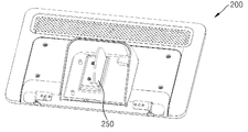
상기와 같이, 디스플레이 장치(200)이 고정 모드 및 회동 모드로 설정되기 위해, 의료 기기(10)는, 본체(100)에 배치된 제1 잠금 부재(140)와 디스플레이 장치(200)에 배치되며 제1 잠금 부재(140)와 탈부착되는 제2 잠금 부재(250)를 더 포함할 수 있다. 제1 잠금 부재(140)는 본체(100) 중 디스플레이 장치(200)과 마주하는 면 예를 들어, 상면에 배치될 수 있다. 그리고, 제2 잠금 부재(250)는 디스플레이 장치(200) 중 본체(100)와 마주하는 면, 예를 들어, 하면에 배치될 수 있다. 그리하여, 제1 잠금 부재(140)가 제2 잠금 부재(250)에 부착됨으로써 의료 기기(10)의 모드는 고정 모드가 되고, 디스플레이 장치(200)과 본체(100)간의 사이각(θ)은 고정된다. 또한, 제2 잠금 부재(250)가 제1 잠금 부채와 분리됨으로써 의료 기기(10)의 모드는 회동 모드가 되고, 사용자의 움직임에 따라 디스플레이 장치(200)과 본체(100)간의 사이각(θ)이 조절될 수 있다. As described above, in order for the
상기한 제1 잠금 부재(140)와 제2 잠금 부재(250)는 자기력에 의해 부착될 수 있다. 예를 들어, 제1 잠금 부재(140)는 자석을 포함하고, 제2 잠금 부재(250)는 자석을 포함할 수 있다. 특히, 제1 잠금 부재(140)는 전류 공급 여부에 따라 자성을 갖는 영전자석일 수 있다. The
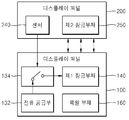
예를 들어, 제어부(130)는 제1 잠금 부재(140)에 전류를 공급하는 전류 공급부(132) 및 센서(240)로부터 수신된 결과에 따라 전류 공급부(132)의 전류를 제1 잠금 부재(140)에 공급하거나 공급하지 않는 스위칭부(134)를 포함할 수 있다. 그리하여, 센서(240)로부터 디스플레이 장치(200)이 터치된다는 결과를 수신하면, 스위칭부(134)는 온되어 전류 공급부(132)는 제1 잠금 부재(140)에 전류를 공급한다. 그리고, 센서(240)로부터 디스플레이 장치(200)이 터치되지 않는다는 결과를 수신하면, 스위칭부(134)는 오프되어 전류 공급부(132)는 제1 잠금 부재(140)에 전류를 공급하지 않는다. For example, the
제1 잠금 부재(140)에 전류가 공급되지 않으면, 제1 잠금 부재(140)는 자성을 갖기 때문에 제1 잠금 부재(140)는 제2 잠금 부재(250)에 부착될 수 있다. 한편, 제1 잠금 부재(140)에 전류가 공급되면, 제1 잠금 부재(140)는 자성을 상실하기 때문에 제1 잠금 부재(140)는 제2 잠금 부재(250)로부터 탈착될 수 있다. The
제1 잠금 부재(140)인 영전자석은 원통형일 수 있고, 제2 잠금 부재(250)는 판형일 수 있다. 그리하여, 영전자석의 단면이 판형의 제2 잠금 부재(250)에 탈부착될 수 있다. 제1 잠금 부재(140)와 제2 잠금 부재(250)는 도면에 도시된 형상 이외에도 다양한 형상이 적용될 수 있음은 물론이다. 그리고, 디스플레이 장치(200)의 회동 범위는 제1 잠금 부재(140)와 제2 잠금 부재(250)의 적어도 일부 영역이 중첩되는 범위일 수 있다. The electromotive magnet as the
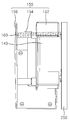
한편, 본체(100)에는 본체(100)에 부착되어 있으면서 제1 잠금 부재(140)를 지지하는 지지 부재(150)가 더 배치될 수 있으며, 지지 부재(150)와 제1 잠금 부재(140) 사이에는 제1 잠금 부재(140)의 움직임에 대응하는 복원력이 생성되는 복원 부재(160)를 더 배치될 수 있다. The
상기한 지지 부재(150)는 내부에 홈이 형성되어 상기한 홈에 제1 잠금 부재(140)가 장착된 브래킷(152), 일단이 브래킷(152)과 접하며 상기한 브래킷(152)이 직선 운동할 수 있도록 가이드하는 샤프트(154), 상기한 샤프트(154)를 본체(100)에 고정시키는 브래킷 하우징(156)을 포함할 수 있다. 복원 부재(160)의 적어도 일부는 샤프트(154) 내에 배치될 수 있다. 상기한 복원 부재(160)는 예를 들어, 스프링을 포함할 수 있다. 그리하여, 자력에 의해 제1 잠금 부재(140)는 제2 잠금 부재(250)가 있는 방향으로 이동하여 제2 잠금 부재(250)에 부착됨으로써 복원 부재(160)에 복원력이 생성될 수 있다. 제1 잠금 부재(140)가 자력을 상실하면, 복원 부재(160)의 복원력에 의해 제1 잠금 부재(140)는 원래의 위치로 복원됨으로써 제1 잠금 부재(140)와 제2 잠금 부재(250)는 이격될 수 있다. 복원력의 방향은 제1 잠금 부재(140)의 이동 방향과 나란하고, 디스플레이 장치(200)의 회동 방향과 수직일 수 있다. 복원력의 방향이 디스플레이 장치(200)의 회동 방향과 수직하게 배치됨으로써 복원력이 디스플레이 장치(200)의 회동에 따른 영향을 최소화할 수 있다. The
일 실시예에서는 지지 부재(150)와 제1 잠금 부재(140) 사이에 복원 부재(160)가 배치된다고 하였다. 복원 부재(160)로 인해 제1 잠금 부재(140)가 제2 잠금 부재(250)로부터 이격되기 때문에 사용자가 디스플레이 장치(200)을 회동시킬 때, 제1 잠금 부재(140)와 제2 잠금 부재(250)의 마찰이 발생하지 않아 사용자는 쉽게 디스플레이 장치(200)을 회동시킬 수 있다. 그러나, 이에 한정되지 않는다. 제1 잠금 부재(140)와 제2 잠금 부재(250)간의 접하는 면에서 마찰력이 거의 발생하지 않는다면, 복원 부재(160) 및 지지 부재(150)는 필요하지 않을 수 있다. In one embodiment, the restoring
일 실시예에서 영전자석이 본체(100)에 배치되고, 전도성 물질이 디스플레이 장치(200)에 배치된다고 하였으나, 이에 한정되지 않는다. 영전자석이 디스플레이 장치(200)에 배치되고, 전도성 물질이 본체(100)에 배치될 수 있다. 이에 따라 지지 부재(150) 및 복원 부재(160)도 디스플레이 장치(200)에 배치될 수 있다. In one embodiment, a permanent magnet is disposed on the
또한, 영전자석이 복원력에 의해 원위치로 복원된다고 하였으나, 이에 한정되지 않는다. 제2 잠금 부재(250)가 복원력에 의해 원위치로 복원될 수 있는 구조로 형성될 수 있음도 물론이다. 그리고, 제어부(130)는 본체(100)에 배치된다고 하였으나, 이에 한정되지 않는다. 제어부(130)는 디스플레이 장치(200)에 배치될 수도 있다. In addition, although the electromotive magnet is restored to the original position by the restoring force, it is not limited thereto. The
도 4는 일 실시예에 따른 사용자의 터치에 따른 의료 기기(10)의 동작방법을 설명하는 흐름도이다. 4 is a flowchart illustrating a method of operating the medical device 10 according to a user's touch according to an embodiment.
도 4를 참조하면, 본체(100) 및 본체(100)와 힌지(230) 연결된 디스플레이 장치(200)을 포함하는 의료 기기(10)에 있어서, 센서(240)는 디스플레이 장치(200)의 터치를 감지한다(S410). 상기한 센서(240)는 디스플레이 장치(200)의 일 영역에 배치되며, 사용자가 파지할 수 있는 영역에 배치될 수 있다. 센서(240)의 감지 결과는 의료기기의 제어부(130)에 인가될 수 있다. 상기한 제어부(130)는 본체(100) 내부에 회로 소자로 형성될 수 있다. 4, the medical device 10 includes a
디스플레이 장치(200)이 미터치된 것으로 감지되면(S410-N), 제어부(130)는 디스플레이 장치(200)의 모드를 디스플레이 장치(200)이 고정되는 고정 모드로 설정할 수 있다(S420). 본체(100)는 제1 잠금 부재(140)가 배치되고, 디스플레이 장치(200)에는 제2 잠금 부재(250)가 배치될 수 있다. 제1 잠금 부재(140)가 제2 잠금 부재(250)에 부착됨으로써 디스플레이 장치(200)의 모드가 고정 모드로 설정될 수 있다. 제1 잠금 부재(140)와 제2 잠금 부재(250)는 자기력에 의해 부착될 수 있다. 예를 들어, 제1 잠금 부재(140)는 전류의 공급 여부에 따라 자성을 띄는 영전자석을 포함할 수 있으며, 제2 잠금 부재(250)는 전도성 물질을 포함할 수 있다. 그리하여, 디스플레이 장치(200)이 미터치된 것으로 감지되면, 영전자석에 전류가 공급되지 않기 때문에 영전자석은 자성을 가져 제2 잠금 부재(250)에 부착될 수 있다. 제1 잠금 부재(140)가 제2 잠금 부재(250)에 부착되기 위해 제1 잠금 부재(140)는 제2 잠금 부재(250) 방향으로 움직일 수 있다. 제1 잠금 부재(140)의 움직임으로 인해, 제1 잠금 부재(140)를 복원 부재(160)는 복원력이 생성될 수 있다. If it is detected that the
그리고, 디스플레이 장치(200)이 터치된 것으로 감지되면(S410-Y), 제어부(130)는 디스플레이 장치(200)의 모드를 디스플레이 장치(200)이 회동 가능한 회동 모드로 설정할 수 있다(S430). 제1 잠금 부재(140)가 제2 잠금 부재(250)로부터 분리됨으로써 디스플레이 장치(200)의 모드가 회동 모드로 설정될 수 있다. 예를 들어, 디스플레이 장치(200)이 터치된 것으로 감지되면, 전류 공급부(132)는 영전자석에 전류를 공급하여 영전자석은 자성을 상실하게 된다. 그리하여 제1 잠금 부재(140)는 제2 잠금 부재(250)에 탈착될 수 있다. 또한, 제1 잠금 부재(140)는 복원 부재(160)의 복원력에 의해 원래의 위치로 복원될 수 있다.If it is detected that the
상기와 같이, 사용자의 터치만으로 디스플레이 장치(200)의 모드를 고정 모드 또는 회동 모드로 설정할 수 있기 때문에 디스플레이 장치(200)을 고정시키거나 디스플레이 장치(200)을 회동시키기 위한 별도의 조작부가 필요하지 않아 사용자에 편의성을 증대시킬 수 있다. As described above, since the mode of the
앞서 기술한 바와 같이, 사이각의 조절로 디스플레이 장치는 상하로 회동할 수 있다. 그러나, 이에 한정되지 않는다. 사이각의 조절로 디스플레이 장치는 본체를 기준으로 좌우 회동할 수도 있다. 이와 같은 경우, 디스플레이 장치의 상하 회동 및 좌우 회동은 힌지의 구조에 따라 결정될 수 있다. As described above, the display device can be rotated up and down by the adjustment of the angle of intersection. However, it is not limited thereto. The display device may be rotated left and right with respect to the main body by adjusting the angle between the two. In such a case, the up-down rotation and the left-right rotation of the display device can be determined according to the structure of the hinge.
전술한 실시예 외의 많은 실시예들이 본 발명의 특허청구범위 내에 존재한다. 본 발명은 다양한 변환을 가할 수 있고 여러 가지 실시예를 가질 수 있는 바, 특정 실시예들을 도면에 예시하고 상세한 설명에 상세하게 설명하고자 한다. 그러나, 이는 본 발명을 특정한 실시 형태에 대해 한정하려는 것이 아니며, 본 발명의 사상 및 기술 범위에 포함되는 모든 변환, 균등물 내지 대체물을 포함하는 것으로 이해되어야 한다.Many embodiments other than the above-described embodiments are within the scope of the claims of the present invention. BRIEF DESCRIPTION OF THE DRAWINGS The present invention is capable of various modifications and various embodiments, and specific embodiments are illustrated in the drawings and described in detail in the detailed description. It is to be understood, however, that the invention is not to be limited to the specific embodiments, but includes all modifications, equivalents, and alternatives falling within the spirit and scope of the invention.
10: 의료 기기 110: 사용자 입력부
130: 제어부 132: 전류 공급부
134: 스위칭부 140: 제1 잠금 부재
150: 지지 부재 160: 복원 부재
200: 디스플레이 장치 210: 표시부
230: 센서 250: 제2 잠금 부재 10: medical instrument 110: user input
130: control unit 132: current supply unit
134: switching part 140: first locking member
150: support member 160: restoring member
200: Display device 210: Display
230: sensor 250: second locking member
Claims (20)
의료 영상을 표시하고, 상기 본체를 기준으로 회동 가능한 디스플레이 장치; 및
상기 디스플레이 장치가 터치된 상태이면 상기 디스플레이 장치가 회동 가능하도록 하고, 상기 디스플레이 장치가 미터치된 상태이면 상기 디스플레이 장치를 고정시키는 잠금 부재;를 포함하는 의료 기기. A main body including a user input portion for receiving a user command;
A display device that displays a medical image and is rotatable with respect to the main body; And
And a locking member for allowing the display device to rotate when the display device is touched and for fixing the display device when the display device is untouched.
상기 디스플레이 장치의 터치를 감지하는 센서;를 더 포함하는 의료 기기. The method according to claim 1,
And a sensor for sensing a touch of the display device.
상기 디스플레이 장치는,
상기 본체를 기준으로 상하 또는 좌우로 회동 가능한 의료 기기. The method according to claim 1,
The display device includes:
Wherein the medical device is vertically or horizontally rotatable relative to the main body.
상기 잠금 부재는,
상기 본체에 배치된 제1 잠금 부재; 및
상기 디스플레이 장치에 배치되며, 상기 제1 잠금 부재와 탈부착되는 제2 잠금 부재;를 더 포함하는 의료 기기. The method according to claim 1,
Wherein,
A first locking member disposed in the main body; And
And a second locking member disposed on the display device and detachably attached to the first locking member.
상기 디스플레이 장치가 터치된 상태이면 상기 제1 잠금 부재와 상기 제2 잠금 부재가 서로 분리되어 상기 디스플레이 장치가 회동 가동하고,
상기 디스플레이 장치가 미터치된 상태이면 상기 제1 잠금 부재는 상기 제2 잠금 부재에 부착되어 상기 디스플레이 장치가 고정되는 의료 기기. 5. The method of claim 4,
When the display device is touched, the first locking member and the second locking member are separated from each other to rotate the display device,
And the first locking member is attached to the second locking member to fix the display device when the display device is untouched.
상기 제1 잠금 부재와 상기 제2 잠금 부재는 자기력에 의해 부착되는 의료 기기. 5. The method of claim 4,
Wherein the first locking member and the second locking member are attached by magnetic force.
상기 제1 잠금 부재와 상기 제2 잠금 부재 중 어느 하나는 자석을 포함하고,
상기 제1 잠금 부재와 상기 제2 잠금 부재 중 나머지 하나는 자성 물질을 포함하는 의료 기기. 6. The method of claim 5,
Wherein either one of the first locking member and the second locking member includes a magnet,
And the other of the first and second locking members comprises a magnetic material.
상기 제1 잠금 부재와 상기 제2 잠금 부재 중 어느 하나는 영전자석을 포함하는 의료 기기. 8. The method of claim 7,
Wherein one of the first locking member and the second locking member includes a permanent magnet.
상기 영전자석에 전류를 공급하는 전류 공급부; 및
상기 디스플레이 장치의 터치 여부에 따라 상기 전류 공급부와 상기 영전자석간의 연결을 온 또는 오프시키는 스위칭부;를 더 포함하는 의료 기기. 9. The method of claim 8,
A current supplying unit for supplying a current to the electromotive magnet; And
And a switching unit for turning on / off the connection between the current supply unit and the electromotive force magnet depending on whether the display device is touched.
상기 스위칭부는,
상기 디스플레이 장치가 미터치된 상태이면 상기 전류 공급부와 상기 영전자석간의 연결을 오프시키고,
상기 디스플레이 장치가 터치된 상태이면 상기 전류 공급부와 상기 영전자석간의 연결을 온시키는 의료 기기. 10. The method of claim 9,
The switching unit includes:
Wherein when the display device is in the untouched state, the connection between the current supply part and the electromotive magnet is turned off,
And turns on the connection between the electric current supplying part and the electromotive magnet when the display device is touched.
상기 제1 잠금 부재와 상기 제2 잠금 부재는 복원력에 의해 이격 배치되는 의료 기기. 5. The method of claim 4,
Wherein the first locking member and the second locking member are spaced apart by a restoring force.
상기 제1 잠금 부재의 움직임에 대응하는 상기 복원력을 생성하는 복원 부재;를 더 포함하는 의료 기기. 12. The method of claim 11,
And a restoring member for generating the restoring force corresponding to the movement of the first locking member.
상기 복원 부재는,
상기 제1 잠금 부재가 움직여 상기 제2 잠금 부재에 부착되면 상기 복원력을 생성하고,
상기 제1 잠금 부재가 상기 제2 잠금 부재로부터 탈착되면 상기 복원력에 의해 상기 제1 잠금 부재를 원래의 위치로 복원되는 의료 기기. 13. The method of claim 12,
The restoration member
Wherein when the first locking member moves and is attached to the second locking member,
And the first locking member is restored to its original position by the restoring force when the first locking member is detached from the second locking member.
상기 복원력의 방향은 상기 디스플레이 장치의 회동 방향과 수직인 의료 기기. 12. The method of claim 11,
And the direction of the restoring force is perpendicular to the turning direction of the display device.
상기 디스플레이 장치의 터치를 감지하는 단계;
상기 디스플레이 장치가 미터치된 것으로 감지되면 상기 디스플레이 장치가 고정되는 고정 모드로 상기 디스플레이 장치의 모드를 설정하는 단계; 및
상기 디스플레이 장치가 터치된 것으로 감지되면 상기 디스플레이 장치가 회동 가능한 회동 모드로 상기 디스플레이 장치의 모드를 설정하는 단계;를 포함하는 의료 기기의 동작 방법. A method of operating a medical device including a main body and a display device hinged to the main body,
Sensing a touch of the display device;
Setting a mode of the display device in a fixed mode in which the display device is fixed when the display device is detected as untouched; And
And setting a mode of the display device in a rotation mode in which the display device is rotatable when the display device is sensed as being touched.
상기 고정 모드로 설정하는 단계는,
상기 본체에 배치된 제1 잠금 부재가 상기 디스플레이 장치에 배치된 제2 잠금 부재에 부착되는 단계;를 포함하고,
상기 회동 모드로 설정하는 단계는,
상기 제1 잠금 부재가 상기 제2 잠금 부재로부터 탈착되는 단계;를 포함하는 의료 기기의 동작 방법. 16. The method of claim 15,
Wherein the setting of the fixed mode comprises:
And attaching a first locking member disposed on the body to a second locking member disposed on the display device,
The step of setting the rotation mode includes:
And the first locking member is detached from the second locking member.
상기 제1 잠금 부재와 상기 제2 잠금 부재는 자기력에 의해 부착되는 의료 기기의 동작 방법. 16. The method of claim 15,
Wherein the first locking member and the second locking member are attached by a magnetic force.
상기 제1 잠금 부재와 상기 제2 잠금 부재 중 어느 하나는 영전자석을 포함하고,
상기 제1 잠금 부재와 상기 제2 잠금 부재 중 나머지 하나는 전도성 물질을 포함하는 의료 기기의 동작 방법. 16. The method of claim 15,
Wherein either one of the first locking member and the second locking member includes a permanent magnet,
Wherein the other of the first and second locking members comprises a conductive material.
상기 디스플레이 장치가 미터치된 것으로 감지되면 상기 영전자석에 전류가 공급되지 않고,
상기 디스플레이 장치가 터치된 것으로 감지되면 상기 영전자석에 전류가 공급되는 의료 기기의 동작 방법. 19. The method of claim 18,
When the display device is detected as being untouched, no current is supplied to the electromotive magnet,
And a current is supplied to the electromotive magnet when the display device is sensed as being touched.
상기 고정 모드로 설정하는 단계는,
복원 부재에 상기 제1 잠금 부재의 움직임에 대응하는 복원력이 생성되는 단계;를 포함하고,
상기 회동 모드로 설정하는 단계는,
상기 복원력에 의해 상기 제1 잠금 부재가 원래의 위치로 복원되는 단계;를 더 포함하는 의료 기기의 동작 방법. 17. The method of claim 16,
Wherein the setting of the fixed mode comprises:
And a restoring force corresponding to the movement of the first locking member is generated in the restoring member,
The step of setting the rotation mode includes:
And restoring the first locking member to its original position by the restoring force.
Applications Claiming Priority (4)
| Application Number | Priority Date | Filing Date | Title |
|---|---|---|---|
| US201461951268P | 2014-03-11 | 2014-03-11 | |
| US61/951,268 | 2014-03-11 | ||
| KR1020140034296 | 2014-03-24 | ||
| KR20140034296 | 2014-03-24 |
Publications (2)
| Publication Number | Publication Date |
|---|---|
| KR20150106308A true KR20150106308A (en) | 2015-09-21 |
| KR102246360B1 KR102246360B1 (en) | 2021-04-29 |
Family
ID=54070609
Family Applications (1)
| Application Number | Title | Priority Date | Filing Date |
|---|---|---|---|
| KR1020140091324A KR102246360B1 (en) | 2014-03-11 | 2014-07-18 | Medical apparuatus and method of operating the medical apparatus |
Country Status (2)
| Country | Link |
|---|---|
| US (1) | US9953754B2 (en) |
| KR (1) | KR102246360B1 (en) |
Citations (1)
| Publication number | Priority date | Publication date | Assignee | Title |
|---|---|---|---|---|
| US20030142080A1 (en) * | 2002-01-30 | 2003-07-31 | Uhl Steve B. | Video image capture system with adjustable control screen |
Family Cites Families (2)
| Publication number | Priority date | Publication date | Assignee | Title |
|---|---|---|---|---|
| KR100968309B1 (en) | 2008-05-30 | 2010-07-08 | (주)메디슨 | Device and method for adjusting display automatically in the ultrasound system |
| US20150036060A1 (en) * | 2013-07-31 | 2015-02-05 | Airgo Design Pte. Ltd. | Passenger Delivery System |
-
2014
- 2014-07-18 KR KR1020140091324A patent/KR102246360B1/en active IP Right Grant
-
2015
- 2015-03-10 US US14/644,018 patent/US9953754B2/en active Active
Patent Citations (1)
| Publication number | Priority date | Publication date | Assignee | Title |
|---|---|---|---|---|
| US20030142080A1 (en) * | 2002-01-30 | 2003-07-31 | Uhl Steve B. | Video image capture system with adjustable control screen |
Also Published As
| Publication number | Publication date |
|---|---|
| KR102246360B1 (en) | 2021-04-29 |
| US9953754B2 (en) | 2018-04-24 |
| US20150264828A1 (en) | 2015-09-17 |
Similar Documents
| Publication | Publication Date | Title |
|---|---|---|
| EP3337419B1 (en) | Reference array holder | |
| EP3318214A1 (en) | Medical imaging device with smartglasses and method for supporting a person using a medical imaging device | |
| CN110741328B (en) | Modular ultrasound system | |
| US20150327841A1 (en) | Tracking in ultrasound for imaging and user interface | |
| US6785578B2 (en) | User input device for controlling medical imaging equipment motion | |
| CN103222881A (en) | Ultrasound diagnosis apparatus having plurality of display units | |
| EP2568306A1 (en) | MRI device comprising an image output unit | |
| KR20130113775A (en) | Acoustic probe and acoustic diagnostic system including the same | |
| JP6176832B2 (en) | Support device and X-ray diagnostic apparatus | |
| CN111432729B (en) | X-ray CT photographing device | |
| US11337661B2 (en) | Medical navigation system with wirelessly connected, touch-sensitive screen | |
| EP3454770A1 (en) | Image marker-based navigation using a tracking frame | |
| CN113520425A (en) | Medical imaging system, interventional system and control method thereof | |
| US6512373B1 (en) | Magnetic resonance tomography device having an operator control and monitoring device with a spatially modifiable apparatus for defining an orientation of a tomographic image | |
| US20150033195A1 (en) | Hardware device, user control apparatus for the same, medical apparatus including the same, and method of operating medical apparatus | |
| KR102246360B1 (en) | Medical apparuatus and method of operating the medical apparatus | |
| WO2011092468A1 (en) | Controller | |
| Menon et al. | Mapping stiffness perception in the brain with an fMRI-compatible particle-jamming haptic interface | |
| JP7141182B2 (en) | Radiation image display device, image display method and control program | |
| KR100925641B1 (en) | Display system for displaying interior of the body | |
| US8576980B2 (en) | Apparatus and method for acquiring sectional images | |
| US10251623B2 (en) | Support apparatus of ultrasound probe, handsfree ultrasound probe including the support apparatus, and method of operating the support apparatus | |
| US6424855B1 (en) | Medical diagnostic imaging apparatus | |
| EP4044007A1 (en) | Medical apparatus and method for operating medical apparatus | |
| US20230165564A1 (en) | Ultrasound probe with integrated controls |
Legal Events
| Date | Code | Title | Description |
|---|---|---|---|
| A201 | Request for examination | ||
| E902 | Notification of reason for refusal | ||
| E701 | Decision to grant or registration of patent right |