KR20150100709A - Tavr ventricular catheter - Google Patents
Tavr ventricular catheter Download PDFInfo
- Publication number
- KR20150100709A KR20150100709A KR1020157017529A KR20157017529A KR20150100709A KR 20150100709 A KR20150100709 A KR 20150100709A KR 1020157017529 A KR1020157017529 A KR 1020157017529A KR 20157017529 A KR20157017529 A KR 20157017529A KR 20150100709 A KR20150100709 A KR 20150100709A
- Authority
- KR
- South Korea
- Prior art keywords
- catheter
- distal ring
- aortic valve
- upper shaft
- shaft portion
- Prior art date
Links
Images


Classifications
-
- A—HUMAN NECESSITIES
- A61—MEDICAL OR VETERINARY SCIENCE; HYGIENE
- A61F—FILTERS IMPLANTABLE INTO BLOOD VESSELS; PROSTHESES; DEVICES PROVIDING PATENCY TO, OR PREVENTING COLLAPSING OF, TUBULAR STRUCTURES OF THE BODY, e.g. STENTS; ORTHOPAEDIC, NURSING OR CONTRACEPTIVE DEVICES; FOMENTATION; TREATMENT OR PROTECTION OF EYES OR EARS; BANDAGES, DRESSINGS OR ABSORBENT PADS; FIRST-AID KITS
- A61F2/00—Filters implantable into blood vessels; Prostheses, i.e. artificial substitutes or replacements for parts of the body; Appliances for connecting them with the body; Devices providing patency to, or preventing collapsing of, tubular structures of the body, e.g. stents
- A61F2/02—Prostheses implantable into the body
- A61F2/24—Heart valves ; Vascular valves, e.g. venous valves; Heart implants, e.g. passive devices for improving the function of the native valve or the heart muscle; Transmyocardial revascularisation [TMR] devices; Valves implantable in the body
- A61F2/2427—Devices for manipulating or deploying heart valves during implantation
-
- A—HUMAN NECESSITIES
- A61—MEDICAL OR VETERINARY SCIENCE; HYGIENE
- A61B—DIAGNOSIS; SURGERY; IDENTIFICATION
- A61B5/00—Measuring for diagnostic purposes; Identification of persons
- A61B5/103—Detecting, measuring or recording devices for testing the shape, pattern, colour, size or movement of the body or parts thereof, for diagnostic purposes
- A61B5/107—Measuring physical dimensions, e.g. size of the entire body or parts thereof
- A61B5/1076—Measuring physical dimensions, e.g. size of the entire body or parts thereof for measuring dimensions inside body cavities, e.g. using catheters
-
- A—HUMAN NECESSITIES
- A61—MEDICAL OR VETERINARY SCIENCE; HYGIENE
- A61F—FILTERS IMPLANTABLE INTO BLOOD VESSELS; PROSTHESES; DEVICES PROVIDING PATENCY TO, OR PREVENTING COLLAPSING OF, TUBULAR STRUCTURES OF THE BODY, e.g. STENTS; ORTHOPAEDIC, NURSING OR CONTRACEPTIVE DEVICES; FOMENTATION; TREATMENT OR PROTECTION OF EYES OR EARS; BANDAGES, DRESSINGS OR ABSORBENT PADS; FIRST-AID KITS
- A61F2/00—Filters implantable into blood vessels; Prostheses, i.e. artificial substitutes or replacements for parts of the body; Appliances for connecting them with the body; Devices providing patency to, or preventing collapsing of, tubular structures of the body, e.g. stents
- A61F2/02—Prostheses implantable into the body
- A61F2/24—Heart valves ; Vascular valves, e.g. venous valves; Heart implants, e.g. passive devices for improving the function of the native valve or the heart muscle; Transmyocardial revascularisation [TMR] devices; Valves implantable in the body
- A61F2/2496—Devices for determining the dimensions of the prosthetic valve to be implanted, e.g. templates, sizers
-
- A—HUMAN NECESSITIES
- A61—MEDICAL OR VETERINARY SCIENCE; HYGIENE
- A61F—FILTERS IMPLANTABLE INTO BLOOD VESSELS; PROSTHESES; DEVICES PROVIDING PATENCY TO, OR PREVENTING COLLAPSING OF, TUBULAR STRUCTURES OF THE BODY, e.g. STENTS; ORTHOPAEDIC, NURSING OR CONTRACEPTIVE DEVICES; FOMENTATION; TREATMENT OR PROTECTION OF EYES OR EARS; BANDAGES, DRESSINGS OR ABSORBENT PADS; FIRST-AID KITS
- A61F2230/00—Geometry of prostheses classified in groups A61F2/00 - A61F2/26 or A61F2/82 or A61F9/00 or A61F11/00 or subgroups thereof
- A61F2230/0063—Three-dimensional shapes
- A61F2230/0091—Three-dimensional shapes helically-coiled or spirally-coiled, i.e. having a 2-D spiral cross-section
-
- A—HUMAN NECESSITIES
- A61—MEDICAL OR VETERINARY SCIENCE; HYGIENE
- A61F—FILTERS IMPLANTABLE INTO BLOOD VESSELS; PROSTHESES; DEVICES PROVIDING PATENCY TO, OR PREVENTING COLLAPSING OF, TUBULAR STRUCTURES OF THE BODY, e.g. STENTS; ORTHOPAEDIC, NURSING OR CONTRACEPTIVE DEVICES; FOMENTATION; TREATMENT OR PROTECTION OF EYES OR EARS; BANDAGES, DRESSINGS OR ABSORBENT PADS; FIRST-AID KITS
- A61F2250/00—Special features of prostheses classified in groups A61F2/00 - A61F2/26 or A61F2/82 or A61F9/00 or A61F11/00 or subgroups thereof
- A61F2250/0058—Additional features; Implant or prostheses properties not otherwise provided for
- A61F2250/0096—Markers and sensors for detecting a position or changes of a position of an implant, e.g. RF sensors, ultrasound markers
- A61F2250/0098—Markers and sensors for detecting a position or changes of a position of an implant, e.g. RF sensors, ultrasound markers radio-opaque, e.g. radio-opaque markers
-
- A—HUMAN NECESSITIES
- A61—MEDICAL OR VETERINARY SCIENCE; HYGIENE
- A61M—DEVICES FOR INTRODUCING MEDIA INTO, OR ONTO, THE BODY; DEVICES FOR TRANSDUCING BODY MEDIA OR FOR TAKING MEDIA FROM THE BODY; DEVICES FOR PRODUCING OR ENDING SLEEP OR STUPOR
- A61M25/00—Catheters; Hollow probes
- A61M25/0021—Catheters; Hollow probes characterised by the form of the tubing
- A61M25/0041—Catheters; Hollow probes characterised by the form of the tubing pre-formed, e.g. specially adapted to fit with the anatomy of body channels
-
- A—HUMAN NECESSITIES
- A61—MEDICAL OR VETERINARY SCIENCE; HYGIENE
- A61M—DEVICES FOR INTRODUCING MEDIA INTO, OR ONTO, THE BODY; DEVICES FOR TRANSDUCING BODY MEDIA OR FOR TAKING MEDIA FROM THE BODY; DEVICES FOR PRODUCING OR ENDING SLEEP OR STUPOR
- A61M25/00—Catheters; Hollow probes
- A61M25/0067—Catheters; Hollow probes characterised by the distal end, e.g. tips
- A61M25/0068—Static characteristics of the catheter tip, e.g. shape, atraumatic tip, curved tip or tip structure
- A61M25/007—Side holes, e.g. their profiles or arrangements; Provisions to keep side holes unblocked
-
- A—HUMAN NECESSITIES
- A61—MEDICAL OR VETERINARY SCIENCE; HYGIENE
- A61M—DEVICES FOR INTRODUCING MEDIA INTO, OR ONTO, THE BODY; DEVICES FOR TRANSDUCING BODY MEDIA OR FOR TAKING MEDIA FROM THE BODY; DEVICES FOR PRODUCING OR ENDING SLEEP OR STUPOR
- A61M25/00—Catheters; Hollow probes
- A61M25/0067—Catheters; Hollow probes characterised by the distal end, e.g. tips
- A61M25/0074—Dynamic characteristics of the catheter tip, e.g. openable, closable, expandable or deformable
-
- A—HUMAN NECESSITIES
- A61—MEDICAL OR VETERINARY SCIENCE; HYGIENE
- A61M—DEVICES FOR INTRODUCING MEDIA INTO, OR ONTO, THE BODY; DEVICES FOR TRANSDUCING BODY MEDIA OR FOR TAKING MEDIA FROM THE BODY; DEVICES FOR PRODUCING OR ENDING SLEEP OR STUPOR
- A61M25/00—Catheters; Hollow probes
- A61M25/01—Introducing, guiding, advancing, emplacing or holding catheters
- A61M25/0105—Steering means as part of the catheter or advancing means; Markers for positioning
- A61M25/0108—Steering means as part of the catheter or advancing means; Markers for positioning using radio-opaque or ultrasound markers
-
- A—HUMAN NECESSITIES
- A61—MEDICAL OR VETERINARY SCIENCE; HYGIENE
- A61M—DEVICES FOR INTRODUCING MEDIA INTO, OR ONTO, THE BODY; DEVICES FOR TRANSDUCING BODY MEDIA OR FOR TAKING MEDIA FROM THE BODY; DEVICES FOR PRODUCING OR ENDING SLEEP OR STUPOR
- A61M25/00—Catheters; Hollow probes
- A61M25/01—Introducing, guiding, advancing, emplacing or holding catheters
- A61M25/09—Guide wires
Abstract
본 발명에 따르면, 경피적 대동맥 판막 치환술 동안 판막을 배치하기 위한 카테터가 가이드와이어가 중공 구조의 바디 내에 있는 상측 개구를 통해 중공 구조의 바디를 통해 통과할 때 가이드와이어에 일치하는 탄성의 중공 구조의 바디로 형성된다. 가이드와이어가 철회될 때에는, 상기 카테터는 펼쳐져서 상기 상측 샤프트 부분에 대해 수직인 원위 링과 상측 개구로부터 하부 방향으로 연장되는 실질적으로 직선의 상측 샤프트 부분을 형성한다. In accordance with the present invention, a catheter for placing a valve during percutaneous aortic valve replacement is configured such that when the guide wire passes through the body of the hollow structure through the upper opening in the body of the hollow structure, . When the guide wire is withdrawn, the catheter is unfolded to form a substantially straight upper shaft portion extending downwardly from the distal ring and the upper opening perpendicular to the upper shaft portion.
Description
본 특허출원은 2012년 12월 5일에 출원되고 발명의 명칭이 "TAVR Ventricular Catheter"인 미국 가특허출원번호 61/733,818호를 기초로 우선권을 주장하고 있으며, 상기 미국 가특허출원은 본 명세서에서 참조문헌으로 인용된다.
This patent application claims priority from U.S. Provisional Patent Application No. 61 / 733,818, filed December 5, 2012, entitled " TAVR Ventricular Catheter ", which is incorporated herein by reference in its entirety Quot; is incorporated herein by reference.
경피적 대동맥 판막 치환술(Transcatheter Aortic Valve Replacement: TAVR)은 대동맥 판막의 협착을 치료하기 위한 방법이다. 협착된 대동맥 판막은 좁아져서 심장으로부터 나오는 혈류를 제한하여 심부전(heart failure) 가능성을 증가시킨다. 경피적 대동맥 판막 치환술(TAVR)은 협착된 대동맥 판막 내에 인조 심장 판막을 이식하기 위한 최소침습접근법(minimally invasive approach)이다. Transcatheter Aortic Valve Replacement (TAVR) is a method for the treatment of aortic valve stenosis. The stenotic aortic valve narrows, limiting blood flow from the heart, increasing the likelihood of heart failure. Percutaneous aortic valve replacement (TAVR) is a minimally invasive approach for transplanting artificial heart valves within the stenotic aortic valve.
TAVR 시술 동안, 심장병 전문의(cardiologist)는 서혜부(groin) 내의 동맥을 통해 튜브(카테터)를 삽입하거나(경대퇴동맥 접근법) 또는 갈비뼈 사이의 작은 절개부를 통해 삽입한다(경심첨부 접근법). 인조 판막은 수축되어 상기 인조 판막이 대동맥 판막에 도달할 때까지 카테터를 통해 공급된다. 풍선(balloon)이 환자의 협착된 대동맥 판막 내에서 인조 판막을 팽창시켜, 기존의 판막을 부러뜨리고(crushing), 카테터는 제거된다. 새로운 판막은 오래된 판막을 대체하여, 체내 전체의 혈류를 증가시킨다. Edwards Lifesciences PVT사에 의해 개발된 TAVR 시술은 US 8,002,825호("Implantable Prosthetic Valve for Treating Aortic Stenosis")에 기술되어 있는데, 이 미국출원도 본 명세서에서 참조문헌으로 인용된다. During the TAVR procedure, a cardiologist inserts a tube (catheter) through the artery in the groin (a femoral artery approach) or inserts through a small incision between the ribs (a median approach). The artificial valve is contracted and fed through the catheter until the artificial valve reaches the aortic valve. A balloon inflates the artificial valve in the patient's stenotic aortic valve, crushing the existing valve, and the catheter is removed. The new valve replaces the old valve, increasing the blood flow throughout the body. The TAVR procedure developed by Edwards Lifesciences PVT is described in US 8,002,825 ("Implantable Prosthetic Valve for Treating Aortic Stenosis ", which is also incorporated herein by reference).
협착된 대동맥 판막 내에 인조 판막을 올바르게 배치하는 것은 TAVR 시술의 성공여부에 있어서 매우 중요한 요인이다. 인조 판막은 부러뜨려진 기존의 협착된 판막 위에 가능한 최대한 정확하게 대동맥 환형(aortic annulus)와 평행하게 배치되어야 한다. 또한, 인조 판막 자체를 올바르게 배치하는 것을 구현하는 데 있어서, 환자의 심장 판막에 대해 심장병 전문의에 의하여 사용되는 영상 장치를 정확하게 배열하는 것도 핵심적인 요인이다. 통상적으로, 심장병 전문의는 대동맥 판막을 촬영하기 위하여 고해상도의 형광투시법(fluoroscopy) 및/또는 영화방사선촬영술(cineradiography)을 사용할 것이다. 이러한 영상에서, 염료(dye)가 대동맥 내에 주입되어, 판막이 영상 스크린 상에서 다소 흐릿한 백색 라인으로서 식별되게 한다. 그 뒤, 심장병 전문의는 영상 장치를 판막에 대해 수직으로 배치하려 할 것이다. 이러한 방법이 가지는 태생적인 부정확성으로 인해, 심장병 전문의는 여러 번의 x-레이 촬영(이와 동일한 횟수의 염료 주입을 포함하여) 을 수행할 필요가 있을 수 있다. 이에 따라, 시술의 소요 시간이 길어지고 환자의 합병증 위험성이 높아진다.
Proper placement of the artificial valve in the stenotic aortic valve is a critical factor in the success of the TAVR procedure. The artificial valve should be placed as parallel to the aortic annulus as possible on the existing stenosed valve that has been broken. Also, in order to properly position the artificial valve itself, it is also a key factor to accurately arrange the imaging device used by the cardiologist for the patient's heart valve. Typically, cardiologists will use high resolution fluoroscopy and / or cinematography to capture the aortic valve. In this image, a dye is injected into the aorta, causing the valve to be identified as a slightly hazy white line on the image screen. After that, the cardiologist will try to position the imaging device perpendicular to the valve. Due to the inherent inaccuracies of this method, the cardiologist may need to perform multiple x-ray exposures (including the same number of dye injections). This increases the time required for the procedure and increases the risk of complications in the patient.
본 발명의 TAVR 심실 카테터는 경대퇴동맥 TAVR 시술 동안 영상 장치의 C-암을 배치하는 데 도움을 준다. 상기 카테터는 강성의 와이어가 릴리스 가능하게 연장되는(releasbly extend) 중공 구조의 탄성 튜브를 포함한다. 와이어가 카테터를 통해 연장될 때, 카테터는 카테터가 대대동맥을 통과할 수 있도록 와이어의 형태에 일치한다(conform). 동맥을 통과하고 나면, 와이어를 제거하여 카테터가 펼쳐질 수 있는데(deployed), 이 지점에서 카테터의 원위 단부(distal end)는 기존의 협착된 판막에 인접하게 배치될 수 있으며 판막 밑에 꼭 맞게 되는(snugly) 일반적인 원형 또는 난형의 링(ring)이 된다. 그러면, 원위 원(distal circle)은 x-레이 C-암을 대동맥 판막 환형(aortic valve annulus)에 대해 수직인 위치로 배치하도록 사용될 수 있다. 적절한 C-암의 각도는 원위 수평 원이 더 이상 원 또는 타원이 아니라 일직선으로 나타날 때 구현된다. 또한, 상기 라인은 판막이 펼쳐지기 전에 판막이 최적으로 배열되기 위한 위치를 식별한다. 이러한 영화방사선촬영술 영상(cine picture)은 실제로 판막이 배치되는 동안 참조를 위해 모니터 스크린 상에 저장될 수 있다. The TAVR ventricular catheter of the present invention assists in positioning the C-arm of the imaging device during the femoral artery TAVR procedure. The catheter includes a resilient tube of hollow structure that releasably extends a rigid wire. As the wire extends through the catheter, the catheter conforms to the shape of the wire so that the catheter can pass through the large aorta. Once through the artery, the wire can be removed and the catheter deployed so that at this point the distal end of the catheter can be placed adjacent to the existing stenotic valve and is snugly ) It becomes a general circular or oval ring. The distal circle can then be used to position the x-ray C-arm in a position perpendicular to the aortic valve annulus. The appropriate C-arm angle is realized when the distal horizontal circle no longer appears as a circle or an ellipse but as a straight line. The line also identifies the location for the valve to be optimally aligned before the valve is unfolded. Such cinematographic cine pictures may be stored on the monitor screen for reference during the actual placement of the valve.
본 발명을 요약하기 위하여, 본 발명의 특정 형태, 이점 및 신규한 특징들이 본 명세서에 기술된다. 이 모든 이점들이 반드시 본 발명의 임의의 한 특정 실시예에 따라서만 구현될 필요는 없다는 사실을 이해해야 한다. 따라서, 본 발명은 본 명세서에서 기술되거나 제안된 것과 같이 그 외의 다른 이점들을 반드시 구현하지 않고도 본 명세서에 기술된 하나의 이점 또는 여러 이점들을 구현하거나 최적화하도록 실시되거나 구현될 수 있다.
To summarize the invention, certain forms, advantages and novel features of the invention are set forth herein. It should be appreciated that not all of these advantages necessarily need to be implemented in accordance with any one specific embodiment of the invention. Thus, the present invention may be embodied or implemented to implement or optimize one or more of the advantages described herein without necessarily implementing other advantages as described or suggested herein.
본 발명은 첨부도면들을 참조하여 읽을 때 보다 더 잘 이해될 수 있다. 도면들의 요소들은 반드시 실측으로 도시된 것은 아니며, 본 발명의 원리를 명확하게 예시하기 위해 확대 강조되어 도시된다. 또한, 유사한 도면부호는 몇몇 도면들에서 이에 상응하는 부분들을 가리킨다.
도 1은 본 발명에 따른 TAVR 심실 카테터의 한 실시예의 전방 투시도이다.
도 2는 도 1에 예시된 대표적인 카테터의 상부 평면도이다.
도 3은 도 1에 예시된 대표적인 카테터의 우측면 평면도이다.
도 4는 도 1에 예시된 대표적인 카테터의 전방 평면도이다.
도 5는 도 1의 카테터를 사용하기 위한 방법의 대표적인 실시예에 따라 좌심실에 삽입되는 가이드와이어를 도시한 도면이다.
도 6은 도 5의 가이드와이어를 따라 환자의 대동맥 안으로 안내되는 카테터를 도시한 도면이다.
도 7은 도 5의 가이드와이어를 따라 환자의 좌심실 안으로 안내되는 카테터를 도시한 도면이다.
도 8은 환자의 좌심실 내에서 펼쳐지는 도 1의 카테터를 도시한 도면이다.
도 9는 철회되어 환자의 대동맥 판막 환형에 대해 꼭 맞게 되는 도 1의 카테터를 도시한 도면이다. The invention may be better understood when read in conjunction with the accompanying drawings. The elements of the figures are not necessarily drawn to scale, but are shown in an enlarged scale to clearly illustrate the principles of the invention. Further, like reference numerals refer to corresponding parts in several figures.
1 is a front perspective view of one embodiment of a TAVR ventricular catheter in accordance with the present invention.
2 is a top plan view of an exemplary catheter illustrated in FIG.
3 is a right side plan view of the exemplary catheter illustrated in Fig.
Figure 4 is a front plan view of an exemplary catheter illustrated in Figure 1;
Figure 5 is a view of a guide wire inserted into a left ventricle according to an exemplary embodiment of a method for using the catheter of Figure 1;
Figure 6 is a view of a catheter that is guided into the patient's aorta along the guide wire of Figure 5;
Figure 7 is a view of a catheter that is guided into the left ventricle of a patient along the guide wire of Figure 5;
Figure 8 is a view of the catheter of Figure 1 deployed in the left ventricle of a patient.
Figure 9 is a view of the catheter of Figure 1, which is retracted to fit into a patient ' s aortic valve annulus.
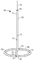
도 1은 본 발명의 대동맥 실시예에 따른 TAVR 심실 카테터(10)의 전방 투시도로서, 카테터(10)는 펼쳐진 형상(deployed configuration)에 있다. 이때, 카테터(10)가 대동맥(도시되지 않음) 내로 삽입될 때, 가이드와이어(16)가 카테터(10)를 통해 완전히 연장된다. 가이드와이어(16)는 카테터(10)보다 더 견고하며 카테터(10)는 가이드와이어(16)가 카테터(10)를 통해 연장될 때 카테터(10)가 가이드와이어(16)의 형태에 일치하도록 부드럽고(soft) 가요성을 지닌다(flexible). 가이드와이어(16)는 카테터(10)를 펼치기 위해 카테터(10)로부터 부분적으로 철회되며, 이는 도 1에 도시된 펼쳐진 형태를 형성한다. 1 is a front perspective view of a TAVR
카테터(10)는 상측 개구(15)와 하측 개구(14)를 가진 중공 구조의 원통형 바디(11)를 포함한다. 카테터(10)는 가이드와이어(16)와 일치하기에 충분히 부드러운 가요성 재료로 일체형으로 형성된다. 한 실시예에서, 카테터(10)는 얇은 벽 압출부(extrusion)를 통해 형성된다. 개구(15 및 14)는 상측 개구(15)를 통해 삽입될 수 있으며 카테터(10)를 통과하여 하측 개구(14)를 통해 삽입될 수 있는 가이드와이어(16)를 수용한다. 가이드와이어(16)가 철회될 때, 상측 샤프트 부분(12)은 일반적으로 일직선이고 상측 개구(15)로부터 외부를 향하는 곡선부(33)(도 3)로 하부 방향으로 연장되는데, 상기 외부를 향하는 곡선부(33)에서 카테터(10)는 하부 방향 및 외부 방향으로 굽어진다. 외부를 향하는 곡선부(33)에 인접한 상부를 향하는 곡선부(34)(도 3)가 상부 방향으로 외부를 향해 연장되어 하측 루프(19)(도 3)를 형성한다. 원위 링(18)이 원형으로 상측 샤프트 부분(12)에 대해 일반적으로 수직으로 연장되어 굽힘부(20)에서 하측 루프(19)와 결합된다(join). The
하측 개구(14)는 카테터(10)의 하측 단부(21)에 배열된다. 복수의 개구(13)가 카테터(10)의 벽을 통해 연장되어 동맥(도시되지 않음)의 영상을 캡쳐(capture)하도록 사용되는 조영제(도시되지 않음)가 유입될 수 있게 한다. The
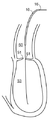
도 2는 도 1의 카테터(10)의 상부 평면도이다. 원위 링(18)은 굽힘부(20)로부터 일반적으로 원형 또는 난형으로(ovally) 연장되며 카테터(10)의 하측 단부(21)에서 종료된다(terminate). 원위 링(18)의 직경은 심실쪽 위에서 환자의 대동맥 환형 링(도시되지 않음)의 직경에 근사하며(approximate), 이는 일반적으로 20 내지 30 mm 범위에 있다. 하측 단부(21)는 굽힘부(20) 가까운 위치에서 종료되지만 굽힘부와 접촉하지는 않는다. 하측 루프(19)는 상측 샤프트 부분(12)으로부터 외부를 향하는 곡선부(33)(도 3), 상부를 향하는 곡선부(34)(도 3) 및 굽힘부(20)를 통해 원위 링(18)으로 연장된다. 도시된 것과 같이 상부로부터 보면, 하측 루프(19)는 원위 링(18)과 상측 샤프트 부분(12) 사이에서 실질적으로 일직선으로 보인다. 2 is a top plan view of the
카테터(10)의 상측 샤프트 부분(12)은, 예시된 실시예에서 상부로부터 카테터(10)를 봤을 때, 원위 링(18) 내의 중앙에 배열된다. 이 형상은, 카테터(10)가 펼쳐질 때 상측 샤프트 부분(12)이 대동맥 판막(도시되지 않음)을 통해 연장되고 원위 링(18)은 대동맥 판막의 소엽(leaflet)(도시되지 않음) 밑에 배열될 수 있게 하는데, 이는 본 명세서의 도 9에 관해 밑에서 더 논의될 것이다. 달리 말하면, 대동맥 판막 내의 개구들이 일반적으로 판막의 중앙에 위치되기 때문에, 상측 샤프트 부분(12)은 일반적으로 원위 링(18)의 중앙에 위치된다. The
도 3은 도 1의 카테터(10)의 측면 평면도이다. 상기 실시예에서, 원위 링(18)은 상측 샤프트 부분(12)에 대해 일반적으로 수직이다. 이보다 중요한 사실에 따르면, 원위 링(18)의 외측 표면은 방사선 불투과성(radiopaque)인데 즉 x-레이 형광투시법(fluoroscopy) 하에서 식별할 수 있다(discernible). 3 is a side plan view of the
하측 루프(19)는 상측 샤프트 부분(12)으로부터 하부 방향으로 외부를 향해 굽어진 외부를 향하는 곡선부(33) 및 외부를 향하는 곡선부(33)로부터 상부 방향으로 외부를 향해 굽어진 상부를 향하는 곡선부(34)로 구성된다. 굽힘부(20)는 상부를 향하는 곡선부(34)를 원위 링(18)에 연결한다. 하측 루프(19)는 원위 링(18)을 포함하는 평면 밑으로 연장된다. 한 실시예에서, 하측 루프(19)는 일반적으로 반원 형태이다. The
카테터(10)의 그 외의 다른 실시예들은 하측 루프(19)를 포함하지 않지만, 대신, 상측 샤프트 부분(12)이 원위 루프(18)의 평면에서 일반적으로 90도 굽어지고 튜브의 직선 부분은 (원위 루프(18)와 동일한 평면에서) 원위 루프(18)를 상측 샤프트 부분(12)에 결합시킨다. 이러한 실시예에서, 카테터(10)는 측면으로부터 봤을 때 뒤집혀진 "T"자 형태로 도시된다. Other embodiments of the
도 4는 도 1의 카테터(10)의 전방 평면도이다. 위에서 논의된 것과 같이, 하측 단부(21)는 굽힘부(20)에 가까운 위치에서 종료된다. 굽힘부(20)는 하측 루프(19)를 원위 링(18)으로 전이시킨다(transition). Figure 4 is a front plan view of the
종래 기술에 알려져 있는 TAVR 심실 카테터(일반적으로 미국 특허번호 8,002,825호에 기술됨)에서, 우선 삽입 와이어(entry wire)가 대퇴동맥 내의 천공부(puncture) 내에 삽입되어 대동맥을 통해 전진된다(advanced). 종래 기술에 알려져 있는 통상적인 가이드 카테터(도시되지 않음)(예컨대, Amplatz 좌심실 카테터)가 삽입 와이어를 따라 전진되고 대동맥 판막을 가로질러(cross) 좌심실 공동(cavity) 내로 삽입되도록 사용된다. 가이드와이어는 철회되고 더 견고한 와이어로 교체되는데, 이 와이어는, 추후에 교체 판막이 설치되기 전에, 협착된 대동맥 판막을 개방시키고 "부러뜨리도록(crush)" 사용되는 풍선용 가이드와이어로서 사용된다. 그 뒤, 종래의 가이드 카테터가 철회된다. In a TAVR ventricular catheter (generally described in U.S. Patent No. 8,002,825) known in the art, an entry wire is first advanced into the femoral artery through a puncture and advanced through the aorta. A conventional guide catheter (not shown) (e.g., an Amplatz left ventricular catheter) known in the art is used to advance along the insertion wire and to cross the aortic valve and into the left ventricular cavity. The guide wire is withdrawn and replaced with a more rigid wire that is used as a guide wire for balloons used to open and "crush" the stenotic aortic valve before the replacement valve is subsequently installed. The conventional guide catheter is then withdrawn.
이제, 도 5-9에 예시된 것과 같이, 본 발명에 따라 카테터(10)를 설치하는 방법이 시작된다. 도 5를 보면, 가이드와이어(16)는 환자의 대동맥(50)을 통해 전진하여 대동맥 판막 환형(aortic valve annulus)(51)을 가로질러 좌심실 공동(53) 안으로 삽입된다. [위에서 논의된 풍선 가이드와이어(balloon guide wire)는 도 5-9에 도시되지 않는데, 이는 카테터(10)를 사용하고 설치하는 방법에 관한 것이기 아니기 때문이라는 것을 유의하라]. 도 6에 도시된 것과 같이, 카테터(10)는 가이드와이어(16)를 따라 전진하여 환자의 대동맥 안으로 삽입된다. 카테터(10)는 가이드와이어(16)의 형태에 일치한다. Now, as illustrated in FIGS. 5-9, a method for installing the
도 7은 카테터(10)가 대동맥 판막 환형(51)을 통과할 때까지 중공 구조의 원통형 바디(11)의 대부분이 대동맥 판막 환형(51)을 통과하여 좌심실 공동(53) 안으로 삽입되도록 가이드와이어(16)를 따라 전진하는 카테터(10)를 도시한다. 그 뒤, 가이드와이어(16)는, 도 8에 예시된 것과 같이, 카테터(10)의 바디(11)가 좌심실 내에서 펼쳐진 상태(deployed state)를 재시작할 수 있도록 카테터(10)로부터 철회된다. 그 뒤, 심장병 전문의는 원위 링(18)이 수축될 때까지 철회되어 도 9에 도시된 것과 같이 대동맥 판막 환형(51)에 대해 꼭 맞게 된다(snugly against). 7 shows a state in which the majority of the
방사선 불투과성 유체(도시되지 않음)가 카테터(10)를 통해 주입되어 개구(13)(도 1)을 통해 좌심실 공동(53) 안으로 살포될 수 있다(perfuse). 그러면, 심장병 전문의는 형광투시법에 의해 방사선 불투과성 원위 링(18)이 협착된 대동맥 판막과 꼭 맞게 접촉되는(snugly contacting) 것을 관측할 수 있다. 이 경우, 협착된 대동맥 판막의 석회화(calcification)가 형광투시법에 의해 카테터(10)의 방사선 불투과성 원위 링(18)에 직접 인접한 것으로 보여질 수 있다. A radiopaque fluid (not shown) may be injected through the
그 뒤, 방사선 불투과성 원위 링(18)은 대동맥 판막 환형(51)과 공평면(coplanar) 위치에 있는 x-레이 C-암(도시되지 않음)에 위치되도록 사용될 수 있다. 적절한 C-암 각도는 방사선 불투과성 원위 링(18)이 더 이상 원 또는 타원으로 나타나지 않고 일직선으로 나타날 때 구현된다. 또한, 상기 라인은 판막이 펼쳐지기 전에 판막이 최적으로 배열되기 위한 위치를 식별한다. 이러한 영화방사선촬영술 영상(cine picture)은 실제로 판막이 배치되는 동안 참조를 위해 모니터 스크린 상에 저장될 수 있다. Thereafter, the radiopaque
C-암이 적절하게 위치되고 난 뒤, 심장병 전문의는 도 11에 도시된 것과 같이 카테터(10)가 가이드와이어(16)의 형태를 재시작하도록 가이드와이어(16)를 전진시킬 수 있다. After the C-arm is properly positioned, the cardiologist can advance the
Claims (22)
가이드와이어가 중공 구조의 바디를 통해 중공 구조의 바디 내에 있는 상측 개구를 통해 통과할 때 가이드와이어에 일치할 수 있는 탄성의 중공 구조의 바디를 포함하고, 상기 탄성의 중공 구조의 바디는 가이드와이어가 중공 구조의 바디로부터 철회될 때 펼쳐진 형태로 펼쳐질 수 있으며, 상기 펼쳐진 형태는:
- 상측 개구로부터 하부 방향으로 연장되는 직선의 상측 샤프트 부분;
- 중공 구조의 바디가 상측 샤프트 부분으로부터 외부 방향으로 굽어지는 외부를 향하는 곡선부;
- 외부를 향하는 곡선부와 상기 외부를 향하는 곡선부에 인접한 중공 구조의 바디의 상부를 향하는 곡선부에 의해 형성된 하측 루프;
- 중공 구조의 바디의 하측 단부에 형성된 원위 링을 포함하며, 상기 원위 링은 굽힘부에 의해 하측 루프에 연결되고, 상기 원위 링은 방사선 불투과성 외측 표면을 포함하며, 상기 원위 링은 상측 샤프트 부분에 대해 수직으로 배열되고;
- 중공 구조의 바디의 하측 단부에 있는 하측 개구를 포함하며, 상기 하측 개구는 중공 구조의 바디를 통과할 때 가이드와이어를 수용하도록 구성되는 것을 특징으로 하는 경피적 대동맥 판막 치환술 동안 판막을 배치하기 위한 카테터. A catheter for placing a valve during percutaneous aortic valve replacement, the catheter comprising:
Wherein the body of the resilient hollow structure includes a guide wire, the guide wire having a resiliently resiliently resilient, resiliently resilient, resiliently resilient, And may be deployed in an unfolded form when withdrawn from the hollow body,
A straight upper shaft portion extending downward from the upper opening;
An outwardly curved portion in which the hollow body is bent outwardly from the upper shaft portion;
A lower loop formed by a curved portion facing outward and a curved portion facing the upper portion of the hollow structure adjacent to the outward facing curved portion;
- a distal ring formed at the lower end of the hollow body, the distal ring being connected to the lower loop by a bend, the distal ring comprising a radiopaque outer surface, the distal ring comprising an upper shaft portion Lt; / RTI >
A lower opening at the lower end of the hollow body, the lower opening configured to receive a guide wire as it passes through the body of the hollow structure; and a catheter for placing a valve during percutaneous aortic valve replacement, .
- 복수의 곡선부를 통해 원위 링에 연결된 직선의 상측 샤프트 부분을 포함하며, 상기 상측 샤프트 부분은 원위 링에 대해 수직으로 배열되고, 상기 원위 링, 상측 샤프트 부분 및 복수의 곡선부는 모두 탄성의 중공 구조의 튜브로 일체형으로 형성되는 것을 특징으로 하는 중공 구조의 바디를 가진 카테터. A distal ring approximating the size and shape of the aortic valve annulus of the patient, said distal ring comprising a plurality of openings and a radiopaque outer surface for dispensing a contrast agent;
An upper shaft portion of a straight line connected to the distal ring through a plurality of curved portions, the upper shaft portion being arranged perpendicular to the distal ring, the distal ring, the upper shaft portion and the plurality of curved portions being all of a resilient hollow structure Wherein the catheter is formed integrally with the tube of the hollow body.
- 가이드와이어를 환자의 대동맥 안으로 전진시켜 환자의 대동맥 판막 환형을 가로질러 환자의 좌심실 공동 안으로 삽입하는 단계;
- 펼쳐지지 않은 카테터를 가이드와이어를 따라 환자의 대동맥 안으로 전진시켜 환자의 대동맥 판막 환형을 가로질러 환자의 좌심실 공동 안으로 삽입하는 단계;
- 펼져지지 않은 카테터가 펼쳐져서 펼쳐진 카테터를 형성할 때까지 가이드와이어를 철회하는 단계를 포함하고, 상기 펼쳐진 카테터는:
환자의 대동맥 판막 환형의 크기와 형태에 근사하는(approximating) 원위 링을 포함하며, 상기 원위 링은 조영제를 살포하기 위해 복수의 개구와 방사선 불투과성 외측 표면을 포함하고;
복수의 곡선부를 통해 원위 링에 연결된 직선의 상측 샤프트 부분을 포함하며, 상기 상측 샤프트 부분은 원위 링에 대해 수직으로 배열되고, 상기 원위 링, 상측 샤프트 부분 및 복수의 곡선부는 모두 탄성의 중공 구조의 튜브로 일체형으로 형성되고;
- 펼쳐진 카테터가 환자의 대동맥 판막 환형과 꼭 맞게 접촉될(snugly contact) 때까지 상기 펼쳐진 카테터를 철회하는 단계;
- 펼쳐진 카테터 안에 방사선 불투과성 유체를 주입하는 단계;
- 원위 링의 영상을 이용하여 C-암을 배치하는 단계를 포함하는 것을 특징으로 하는 x-레이 C-암을 대동맥 판막과 공평면에서 나란하게 정렬되도록 배치하는 방법. A method of placing an x-ray C-arm in alignment with a coplanar with an aortic valve, the method comprising:
- advancing the guide wire into the patient's aorta and inserting it into the patient's left ventricular cavity across the aortic valve annulus of the patient;
Advancing the unfolded catheter along the guide wire into the patient's aorta and inserting it into the patient's left ventricular cavity across the aortic valve annulus of the patient;
Withdrawing the guide wire until the unexpanded catheter is unfolded to form an unfolded catheter, the deployed catheter comprising:
A distal ring approximating the size and shape of the aortic valve annulus of the patient, the distal ring comprising a plurality of openings and a radiopaque outer surface for dispensing a contrast agent;
Wherein the upper shaft portion is arranged perpendicular to the distal ring, and wherein the distal ring, the upper shaft portion, and the plurality of curved portions are all of a resilient hollow structure Formed integrally with the tube;
Withdrawing the deployed catheter until the deployed catheter snugly contacts the patient ' s aortic valve annulus;
Injecting a radiopaque fluid into the deployed catheter;
Placing an x-ray C-arm with the aortic valve in alignment with the aortic valve in a co-plane.
Applications Claiming Priority (3)
| Application Number | Priority Date | Filing Date | Title |
|---|---|---|---|
| US201261733818P | 2012-12-05 | 2012-12-05 | |
| US61/733,818 | 2012-12-05 | ||
| PCT/US2013/073291 WO2014089284A1 (en) | 2012-12-05 | 2013-12-05 | Tavr ventricular catheter |
Publications (1)
| Publication Number | Publication Date |
|---|---|
| KR20150100709A true KR20150100709A (en) | 2015-09-02 |
Family
ID=50826168
Family Applications (1)
| Application Number | Title | Priority Date | Filing Date |
|---|---|---|---|
| KR1020157017529A KR20150100709A (en) | 2012-12-05 | 2013-12-05 | Tavr ventricular catheter |
Country Status (7)
| Country | Link |
|---|---|
| US (3) | US20140155994A1 (en) |
| EP (1) | EP2928536A4 (en) |
| JP (1) | JP2016502445A (en) |
| KR (1) | KR20150100709A (en) |
| CN (1) | CN105007971A (en) |
| CA (1) | CA2893163A1 (en) |
| WO (1) | WO2014089284A1 (en) |
Families Citing this family (12)
| Publication number | Priority date | Publication date | Assignee | Title |
|---|---|---|---|---|
| WO2016065278A1 (en) * | 2014-10-24 | 2016-04-28 | Helmer Gregory | Catheter for tavr procedures |
| CN104815382A (en) * | 2015-04-01 | 2015-08-05 | 吴会勇 | Angiographic catheter for bronchial arteries |
| WO2017120325A1 (en) * | 2016-01-05 | 2017-07-13 | Mcdonald Michael B | Above-the-valve tavr ventricular catheter |
| US10898682B2 (en) * | 2016-02-29 | 2021-01-26 | Michael B. McDonald | Microtube guide |
| US10898322B2 (en) * | 2016-02-29 | 2021-01-26 | Michael B. McDonald | TAVR valve guidewire and guidetube with adjustable distal loop |
| US11083875B2 (en) * | 2016-02-29 | 2021-08-10 | Michael B. McDonald | Hybrid microcatheter guidewire |
| WO2017205355A1 (en) * | 2016-05-23 | 2017-11-30 | Mcdonald Michael B | Microtube guide |
| WO2018045156A2 (en) * | 2016-08-31 | 2018-03-08 | Medtronic Vascular Inc. | Transcatheter guidewire delivery systems, catheter assemblies for guidewire delivery, and methods for percutaneous guidewire delivery across heart valves |
| US20180056045A1 (en) * | 2016-08-31 | 2018-03-01 | Medtronic Vascular, Inc. | Transcatheter guidewire delivery systems, catheter assemblies for guidewire delivery, and methods for percutaneous guidewire delivery across heart valves |
| US10456252B2 (en) * | 2016-08-31 | 2019-10-29 | Medtronic Vascular, Inc. | Transcatheter guidewire delivery systems, catheter assemblies for guidewire delivery, and methods for percutaneous guidewire delivery across heart valves |
| EP4352739A2 (en) * | 2021-06-07 | 2024-04-17 | Dasisimulations, Llc | Systems and methods for optimizing medical interventions using predictive models |
| WO2024013703A2 (en) * | 2022-07-13 | 2024-01-18 | Sv Swissvortex Ag | Spiral guidewires |
Family Cites Families (10)
| Publication number | Priority date | Publication date | Assignee | Title |
|---|---|---|---|---|
| US4169464A (en) * | 1977-12-16 | 1979-10-02 | Cordis Corporation | Catheter for selective catheterization of aortic branches |
| US4694838A (en) * | 1984-01-30 | 1987-09-22 | Mallinckrodt, Inc. | Loop coronary catheter |
| US4738667A (en) * | 1986-11-04 | 1988-04-19 | Galloway Niall T M | Preformed catheter assembly |
| US5163928A (en) * | 1991-01-07 | 1992-11-17 | Franklin Electronic Publishers, Incorporated | Self-centering catheter |
| US6004280A (en) * | 1997-08-05 | 1999-12-21 | Cordis Corporation | Guiding sheath having three-dimensional distal end |
| GB2399017B (en) * | 2003-03-05 | 2005-01-19 | Lars Andrews | Aortic catheter |
| DE102008033137A1 (en) * | 2008-07-15 | 2010-02-04 | Siemens Aktiengesellschaft | Method and device for setting a dynamically adaptable position of an imaging system |
| EP2389218A4 (en) * | 2009-01-20 | 2012-06-13 | Guided Delivery Systems Inc | Diagnostic catheters, guide catheters, visualization devices and chord manipulation devices, and related kits and methods |
| WO2011015218A1 (en) * | 2009-08-06 | 2011-02-10 | Ls Medcap Gmbh | Catheter with two fenestrations |
| US20140005540A1 (en) * | 2011-01-07 | 2014-01-02 | Innovative Cardiovascular Solutions, Inc. | Angiography Catheter |
-
2013
- 2013-12-05 JP JP2015545837A patent/JP2016502445A/en active Pending
- 2013-12-05 CA CA2893163A patent/CA2893163A1/en not_active Abandoned
- 2013-12-05 EP EP13860255.2A patent/EP2928536A4/en not_active Withdrawn
- 2013-12-05 WO PCT/US2013/073291 patent/WO2014089284A1/en active Application Filing
- 2013-12-05 US US14/097,524 patent/US20140155994A1/en not_active Abandoned
- 2013-12-05 KR KR1020157017529A patent/KR20150100709A/en not_active Application Discontinuation
- 2013-12-05 CN CN201380063412.3A patent/CN105007971A/en active Pending
-
2016
- 2016-10-07 US US15/288,525 patent/US10335276B2/en active Active
-
2019
- 2019-12-04 US US16/602,720 patent/US20200214836A1/en not_active Abandoned
Also Published As
| Publication number | Publication date |
|---|---|
| US20140155994A1 (en) | 2014-06-05 |
| WO2014089284A1 (en) | 2014-06-12 |
| US20170020668A1 (en) | 2017-01-26 |
| US20200214836A1 (en) | 2020-07-09 |
| EP2928536A4 (en) | 2016-08-03 |
| EP2928536A1 (en) | 2015-10-14 |
| US10335276B2 (en) | 2019-07-02 |
| CN105007971A (en) | 2015-10-28 |
| JP2016502445A (en) | 2016-01-28 |
| CA2893163A1 (en) | 2014-06-12 |
Similar Documents
| Publication | Publication Date | Title |
|---|---|---|
| KR20150100709A (en) | Tavr ventricular catheter | |
| US11622854B2 (en) | Method for delivery of prosthetic aortic valve | |
| US11938028B2 (en) | Method for implanting a prosthetic heart valve | |
| US9259317B2 (en) | System and method for implanting a heart implant | |
| US11903832B2 (en) | Transcatheter artificial cusp for valve insufficiency | |
| EP2699200B1 (en) | Transcatheter prosthetic heart valve delivery system with flush port | |
| CN101309654B (en) | Transapical heart valve delivery system | |
| US20090030510A1 (en) | Methods and apparatus for percutaneous aortic valve replacement | |
| EP2922501A1 (en) | Device for the deployment of a system of guide wires within a cardiac chamber for implanting a prosthetic heart valve | |
| WO2014080338A1 (en) | Device for the deployment of a system of guide wires within a cardiac chamber for implanting a prosthetic heart valve | |
| US11504233B2 (en) | Valve introducers with adjustable deployment mechanism and implantation depth gauge | |
| US10888297B2 (en) | Above-the-valve TAVR ventricular catheter | |
| WO2017120325A1 (en) | Above-the-valve tavr ventricular catheter |
Legal Events
| Date | Code | Title | Description |
|---|---|---|---|
| WITN | Withdrawal due to no request for examination |