KR20150100531A - Screw fastener - Google Patents
Screw fastener Download PDFInfo
- Publication number
- KR20150100531A KR20150100531A KR1020150025146A KR20150025146A KR20150100531A KR 20150100531 A KR20150100531 A KR 20150100531A KR 1020150025146 A KR1020150025146 A KR 1020150025146A KR 20150025146 A KR20150025146 A KR 20150025146A KR 20150100531 A KR20150100531 A KR 20150100531A
- Authority
- KR
- South Korea
- Prior art keywords
- shaft portion
- screw
- disk
- spring
- axially
- Prior art date
Links
- 230000002093 peripheral effect Effects 0.000 claims description 17
- 239000000463 material Substances 0.000 claims description 13
- 238000000034 method Methods 0.000 claims description 9
- 238000005260 corrosion Methods 0.000 claims description 8
- 230000007797 corrosion Effects 0.000 claims description 8
- 230000036316 preload Effects 0.000 claims description 5
- 239000011248 coating agent Substances 0.000 claims description 2
- 238000000576 coating method Methods 0.000 claims description 2
- 230000008878 coupling Effects 0.000 abstract description 2
- 238000010168 coupling process Methods 0.000 abstract description 2
- 238000005859 coupling reaction Methods 0.000 abstract description 2
- 230000007246 mechanism Effects 0.000 description 3
- 230000008569 process Effects 0.000 description 3
- 229910000831 Steel Inorganic materials 0.000 description 2
- 239000002184 metal Substances 0.000 description 2
- 230000000149 penetrating effect Effects 0.000 description 2
- 239000007787 solid Substances 0.000 description 2
- 229910001220 stainless steel Inorganic materials 0.000 description 2
- 239000010935 stainless steel Substances 0.000 description 2
- 239000010959 steel Substances 0.000 description 2
- 238000000429 assembly Methods 0.000 description 1
- 230000005540 biological transmission Effects 0.000 description 1
- 230000006835 compression Effects 0.000 description 1
- 238000007906 compression Methods 0.000 description 1
- 230000005489 elastic deformation Effects 0.000 description 1
- 238000012423 maintenance Methods 0.000 description 1
- 230000004048 modification Effects 0.000 description 1
- 238000012986 modification Methods 0.000 description 1
- 230000008439 repair process Effects 0.000 description 1
- 230000003252 repetitive effect Effects 0.000 description 1
Images


Classifications
-
- F—MECHANICAL ENGINEERING; LIGHTING; HEATING; WEAPONS; BLASTING
- F16—ENGINEERING ELEMENTS AND UNITS; GENERAL MEASURES FOR PRODUCING AND MAINTAINING EFFECTIVE FUNCTIONING OF MACHINES OR INSTALLATIONS; THERMAL INSULATION IN GENERAL
- F16B—DEVICES FOR FASTENING OR SECURING CONSTRUCTIONAL ELEMENTS OR MACHINE PARTS TOGETHER, e.g. NAILS, BOLTS, CIRCLIPS, CLAMPS, CLIPS OR WEDGES; JOINTS OR JOINTING
- F16B31/00—Screwed connections specially modified in view of tensile load; Break-bolts
- F16B31/02—Screwed connections specially modified in view of tensile load; Break-bolts for indicating the attainment of a particular tensile load or limiting tensile load
-
- F—MECHANICAL ENGINEERING; LIGHTING; HEATING; WEAPONS; BLASTING
- F16—ENGINEERING ELEMENTS AND UNITS; GENERAL MEASURES FOR PRODUCING AND MAINTAINING EFFECTIVE FUNCTIONING OF MACHINES OR INSTALLATIONS; THERMAL INSULATION IN GENERAL
- F16B—DEVICES FOR FASTENING OR SECURING CONSTRUCTIONAL ELEMENTS OR MACHINE PARTS TOGETHER, e.g. NAILS, BOLTS, CIRCLIPS, CLAMPS, CLIPS OR WEDGES; JOINTS OR JOINTING
- F16B31/00—Screwed connections specially modified in view of tensile load; Break-bolts
- F16B31/02—Screwed connections specially modified in view of tensile load; Break-bolts for indicating the attainment of a particular tensile load or limiting tensile load
- F16B31/027—Screwed connections specially modified in view of tensile load; Break-bolts for indicating the attainment of a particular tensile load or limiting tensile load with a bolt head causing the fastening or the unfastening tool to lose the grip when a specified torque is exceeded
-
- B—PERFORMING OPERATIONS; TRANSPORTING
- B25—HAND TOOLS; PORTABLE POWER-DRIVEN TOOLS; MANIPULATORS
- B25B—TOOLS OR BENCH DEVICES NOT OTHERWISE PROVIDED FOR, FOR FASTENING, CONNECTING, DISENGAGING OR HOLDING
- B25B13/00—Spanners; Wrenches
- B25B13/58—Jaw attachments
-
- B—PERFORMING OPERATIONS; TRANSPORTING
- B25—HAND TOOLS; PORTABLE POWER-DRIVEN TOOLS; MANIPULATORS
- B25B—TOOLS OR BENCH DEVICES NOT OTHERWISE PROVIDED FOR, FOR FASTENING, CONNECTING, DISENGAGING OR HOLDING
- B25B23/00—Details of, or accessories for, spanners, wrenches, screwdrivers
- B25B23/14—Arrangement of torque limiters or torque indicators in wrenches or screwdrivers
-
- F—MECHANICAL ENGINEERING; LIGHTING; HEATING; WEAPONS; BLASTING
- F16—ENGINEERING ELEMENTS AND UNITS; GENERAL MEASURES FOR PRODUCING AND MAINTAINING EFFECTIVE FUNCTIONING OF MACHINES OR INSTALLATIONS; THERMAL INSULATION IN GENERAL
- F16B—DEVICES FOR FASTENING OR SECURING CONSTRUCTIONAL ELEMENTS OR MACHINE PARTS TOGETHER, e.g. NAILS, BOLTS, CIRCLIPS, CLAMPS, CLIPS OR WEDGES; JOINTS OR JOINTING
- F16B39/00—Locking of screws, bolts or nuts
- F16B39/02—Locking of screws, bolts or nuts in which the locking takes place after screwing down
- F16B39/028—Locking of screws, bolts or nuts in which the locking takes place after screwing down by means of an auxiliary bolt or threaded element whose action provokes the deformation of the main bolt or nut and thereby its blocking
-
- F—MECHANICAL ENGINEERING; LIGHTING; HEATING; WEAPONS; BLASTING
- F16—ENGINEERING ELEMENTS AND UNITS; GENERAL MEASURES FOR PRODUCING AND MAINTAINING EFFECTIVE FUNCTIONING OF MACHINES OR INSTALLATIONS; THERMAL INSULATION IN GENERAL
- F16B—DEVICES FOR FASTENING OR SECURING CONSTRUCTIONAL ELEMENTS OR MACHINE PARTS TOGETHER, e.g. NAILS, BOLTS, CIRCLIPS, CLAMPS, CLIPS OR WEDGES; JOINTS OR JOINTING
- F16B19/00—Bolts without screw-thread; Pins, including deformable elements; Rivets
- F16B19/02—Bolts or sleeves for positioning of machine parts, e.g. notched taper pins, fitting pins, sleeves, eccentric positioning rings
Abstract
Description
본 발명은 나사 체결구에 관한 것으로서, 보다 구체적으로는 최대 체결 토크를 설정할 수 있는 토크 리미터(torque limiter)의 기능을 갖춘 볼트 또는 너트에 관한 것이다.BACKGROUND OF THE
토크 리미터의 기능을 갖춘 공지의 체결 볼트에 따르면, 체결 공구가 맞물리도록 구성된 공구 맞물림 헤드를 갖는 헤드 부재, 및 수나사가 형성되며 래칫 기구(ratchet mechanism)를 거쳐서 헤드 부재에 결합되는 수나사 부재를 포함한다. 래칫 기구는, 헤드 부재가 체결 해제 방향(unfastening direction)으로 회전할 때의 상대 운동에 대항하여 헤드 부재 및 수나사 부재를 견고하게 결합시킨다. 헤드 부재가 규정 한계값(최대 체결 토크) 미만의 체결 토크로 체결 방향으로 회전하는 경우, 체결 토크는 스프링에 의해 서로를 향해 가압되어 있는 한쌍의 상호 대향 경사면(mutually opposing slopes)을 거쳐서 헤드 부재로부터 수나사 부재로 전달됨으로써, 체결 토크는 상호 대향 경사면 간의 마찰 결합으로 인해 헤드 부재로부터 수나사 부재로 전달되게 된다. 그러나, 헤드 부재가 규정 한계값 초과의 체결 토크로 회전하는 경우에는, 상호 대향 경사면이 서로 미끄러지기 시작함으로써, 수나사 부재가 규정 한계값 초과의 체결 토크로 너트와 나사 결합하는 것이 방지된다(예컨대, 일본 특허 공개 제 2000-27886 호 공보 참조).According to a known fastening bolt having a function of a torque limiter, a head member having a tool engagement head configured to engage with a fastening tool, and a male screw member formed with a male screw and coupled to the head member via a ratchet mechanism . The ratchet mechanism firmly engages the head member and the male screw member against the relative movement when the head member rotates in the unfastening direction. When the head member rotates in the fastening direction with a fastening torque less than the specified limit value (maximum fastening torque), the fastening torque is transmitted from the head member via a pair of mutually opposing slopes which are urged toward each other by a spring By being transmitted to the male screw member, the tightening torque is transmitted from the head member to the male screw member due to frictional engagement between the mutually opposing slopes. However, when the head member rotates at a tightening torque exceeding a prescribed limit value, the mutually opposing slopes start to slide with respect to each other, so that the male screw member is prevented from being screwed to the nut with the tightening torque exceeding the prescribed limit value Japanese Patent Application Laid-Open No. 2000-27886).
토크 리미터의 기능을 갖춘 공지의 체결 너트에 따르면, 체결 공구가 맞물리도록 구성된 공구 맞물림 헤드를 갖는 헤드 부재, 및 암나사가 형성되며, 서로 마찰 결합하는 상호 대향 스러스트면(mutually opposing thrust surfaces)을 거쳐서 헤드 부재와 맞물리는 암나사 부재를 포함한다. 헤드 부재와 암나사 부재 사이에 개재된 스프링 부재가 상호 대향 스러스트면을 서로를 향해 가압함으로써, 상호 대향 스러스트면 간의 마찰 결합으로 인해, 체결 방향으로의 토크가 헤드 부재로부터 암나사 부재로 전달될 수 있으며, 헤드 부재가 규정 한계값 초과의 토크로 회전하는 경우, 스러스트면이 서로 미끄러짐으로써, 암나사 부재가 규정 한계값 초과의 체결 토크에 의해 대응 수나사와 나사 결합하는 것이 방지된다(예컨대, 일본 특허 공개 제 평10-47326 호 공보 참조).According to known fastening nuts having the function of a torque limiter, a head member having a tool engaging head configured to engage with a fastening tool, and a head member having a female screw formed thereon, and mutually opposing thrust surfaces frictionally engaged with each other, And a female screw member engaged with the member. The spring member interposed between the head member and the female screw member presses the mutually opposing thrust surfaces toward each other so that the torque in the engaging direction can be transmitted from the head member to the female screw member due to the frictional engagement between the mutually opposing thrust surfaces, When the head member rotates at a torque exceeding the specified limit value, the thrust surfaces slide to each other, thereby preventing the female screw member from being screwed to the corresponding male screw by the tightening torque exceeding the prescribed limit value 10-47326).
토크 리미터 기능을 갖춘 종래의 볼트 및 너트는 구조적 복잡성으로 인해 크기가 클 수밖에 없었고, 스프링 가압력을 과도하게 증가시키는 일 없이 큰 토크 한계값을 설정할 수 있도록 구성되어 있지 않았다. 그러므로, 크기뿐만 아니라, 조립 및 분해보수의 어려움도 심각한 문제를 초래한다.Conventional bolts and nuts with torque limiters were too large in size due to their structural complexity and were not configured to set large torque limits without excessive increase in spring force. Therefore, not only the size, but also the difficulty of assembling and disassembling and repairing, causes serious problems.
본 발명의 주요 과제는 나사 체결구의 크기나 스프링 부재의 필요 스프링 힘을 과도하게 증가시키는 일 없이 체결 토크에 대한 고 토크 한계값을 설정할 수 있으며, 조립 및 분해보수가 용이한, 토크 리미터 기능을 갖춘 나사 체결구(예컨대 볼트와 너트)를 제공하는 것이다.A main object of the present invention is to provide a torque limiter that can set a high torque limit value for the tightening torque without excessively increasing the size of the screw fastener or the necessary spring force of the spring member, (For example, a bolt and a nut).
본 발명은, 나사 체결구로서, 축방향 단부에서 회전 공구(turning tool)와 맞물리는 공구 맞물림 특징부(tool engaging feature)(14), 축방향 대향 단부에서 개방된 중심 수용 구멍(central receiving bore)(16), 및 중심 수용 구멍의 개방 단부를 둘러싸는 환상 단부면(18)을 구비하는 제 1 부재(10); 중심 수용 구멍(16) 내에 회전 가능하게 수용되는 관형의 제 2 부재(30)로서, 제 2 부재(30)는 외주부에 둘레 홈(34)이 형성된 끼워맞춤 축부(fitting shaft portion)(32)를 제 2 부재(30)의 축방향 단부에 갖고, 제 2 부재(30)의 축방향 대향 단부에 형성된 수나사(40)를 구비하며, 제 2 부재(30)의 축방향 대향 단부에는 체결 나사(42, 72)가 추가로 마련되며, 제 2 부재의 끼워맞춤 축부(32)와 수나사(40) 사이에는 디스크 지지 축부(disk supporting shaft portion)(36)가 형성되는, 제 2 부재(30); 끼워맞춤 축부(32)의 외주부의 둘레 홈(34) 내에 부분적으로 수용되며, 제 1 부재(10)에 맞물리는 보지 부재(retaining member)(22); 제 1 부재(10)에 고정되며, 제 2 부재(30)를 향해 축방향으로 연장되는 봉 부재(28); 디스크 지지 축부(36)의 외주면에 축방향으로 슬라이딩 가능하고 회전 가능하게 끼워맞춤되며, 봉 부재(28)가 축방향으로 관통하는 관통 구멍(50C)을 갖는 복수의 구동 디스크 부재(50); 디스크 지지 축부(36)의 외주면에 축방향으로 슬라이딩 가능하고 회전 불가능하게 구동 디스크 부재(50)와 축방향으로 교호하도록 끼워맞춤되는 복수의 피동 디스크 부재(52); 구동 디스크 부재(50) 및 피동 디스크 부재(52)를 제 1 부재(10)의 환상 단부면(18) 쪽으로 가압하도록 디스크 지지 축부(36)의 외주면에 배치되는 스프링 부재(58); 및 스프링 부재(58)에 프리로드(preload)를 가하도록 제 2 부재(30)의 수나사(40)에 나사식으로(threadably) 맞물리는 스프링 리테이너(spring retainer)(62)를 포함하는 나사 체결구를 제공한다.The present invention relates to a screw fastener comprising a tool engaging feature (14) engaging with a turning tool at an axial end, a central receiving bore (14) at an axially opposite end, (16), and an annular end face (18) surrounding the open end of the central receiving aperture (16); The
따라서, 제 1 부재와 제 2 부재 사이의 구동 디스크 부재 및 피동 디스크 부재에 의해 다중 플레이트 토크 리미터가 형성되고, 제 1 부재 및 제 2 부재는 보지 부재를 거쳐서 서로 탈착 가능하게 부착됨으로써, 토크 리미터의 크기를 증가시키거나 또는 스프링 부재의 가압력을 증가시키는 일 없이 큰 토크 한계값을 설정할 수 있어서, 토크 리미터 기능을 갖춘 나사 체결구의 조립 및 분해보수의 용이성을 향상시킬 수 있다. 보지 부재는 제 1 부재를 반경방향으로 관통하는 나사 형성 구멍 내에 나사 결합되는 보지 나사(retaining screw)로 구성될 수도 있는데, 이 보지 나사는 둘레 홈 내에 슬라이딩 가능하게 수용되는 자유 단부를 갖는다.Therefore, a multiple plate torque limiter is formed by the drive disk member and the driven disk member between the first member and the second member, and the first member and the second member are detachably attached to each other via the holding member, It is possible to set a large torque limit value without increasing the size or increasing the pressing force of the spring member, so that the ease of assembly and disassembly and repair of the screw fastener having the torque limiter function can be improved. The retaining member may be comprised of a retaining screw threaded into a threaded hole penetrating the first member in a radial direction, the retaining screw having a free end slidably received in the circumferential groove.
바람직하게는, 본 나사 체결구에 있어서, 공구 맞물림 특징부는 다각형 헤드를 포함하고, 디스크 지지 축부는 다각형 헤드와 동일한 공구에 맞물릴 수 있도록 다각형 헤드와 등각인 다각형 단면을 갖는 다각형 축부를 포함하며, 피동 디스크 부재는 다각형 축부에 끼워맞춤됨으로써 제 2 부재에 의해 회전 불가능하게 고정된다.Preferably, in the present threaded fastener, the tool engagement feature comprises a polygonal head, and the disc support shaft portion comprises a polygonal shaft portion having a polygonal cross-section that is conformal to the polygonal head so that it can engage with the same tool as the polygonal head, The driven disk member is fixed to the polygonal shaft portion by the second member in a non-rotatable manner.
따라서, 다각형 축부는 피동 디스크 부재를 회전 불가능하게 고정하는 것과 제 2 부재를 직접 회전시키기 위한 공구와 맞물리는 것의 2가지의 목적을 제공한다. 그러므로, 제 2 부재는 제 1 부재의 회전에 사용되는 것과 동일한 공구를 사용하여 회전될 수 있어서, 2개의 개별 공구를 준비할 필요가 없게 할 수 있다.Accordingly, the polygonal shaft portion serves two purposes of fixing the driven disk member in a non-rotatable manner and engaging with a tool for directly rotating the second member. Therefore, the second member can be rotated using the same tool as that used for rotating the first member, thereby making it unnecessary to prepare two separate tools.
바람직하게는, 본 나사 체결구에 있어서, 구동 디스크 부재와 피동 디스크 부재가 박판을 거쳐서 서로 접촉하는 적어도 하나의 표면에 구동 디스크 부재 및 피동 디스크 부재의 재료보다 내부식성이 높은 박판 또는 코팅이 마련된다.Preferably, in the present screw fastener, a thin plate or coating having higher corrosion resistance than the material of the drive disk member and the driven disk member is provided on at least one surface where the drive disk member and the driven disk member are in contact with each other through the thin plate .
본 구성에 따르면, 부식 등에 의한 마찰면의 고착을, 오일 메탈과 같은 고가의 함유재(oil impregnated material)를 사용하는 일 없이 회피할 수 있다.According to this configuration, it is possible to prevent the friction surface from being adhered due to corrosion or the like without using an oil impregnated material such as oil metal.
본 발명의 바람직한 실시예에 따르면, 제 2 부재(30)에 마련된 체결 나사는 제 2 부재(30)의 축방향 대향 단부에 형성된 중심 구멍 내에 형성된 암나사를 포함한다. 선택적으로, 제 2 부재(30)에 마련된 체결 나사는 제 2 부재(30)의 축방향 대향 단부에 형성된 축방향 연장부에 형성된 수나사를 포함할 수도 있다.According to a preferred embodiment of the present invention, the fastening screw provided on the second member (30) includes a female screw formed in the center hole formed in the axially opposite end of the second member (30). Optionally, the fastening screw provided on the
본 발명의 구체적인 바람직한 실시예에 따르면, 끼워맞춤 축부(32)에 인접한 디스크 지지 축부(36)의 일부의 외주부에 디스크 보지 특징부(disk retaining feature)(36C)가 마련되어서, 구동 및 피동 디스크 부재(50, 52)를 끼워맞춤 축부(32) 쪽으로 축방향 이동하지 못하도록 제한한다.According to a specific preferred embodiment of the present invention, a
따라서, 제 2 부재가 조립 과정 중에 제 1 부재에 접합되기 전에 구동 및 피동 디스크 부재가 제 2 부재에 보지됨으로써 조립 과정이 용이하게 될 수도 있다. 제 1 부재의 대향 환상 단부면은 디스크 보지 특징부를 수용하기 위한 적절한 리세스(recess)를 구비함으로써, 제 1 부재의 환상 단부면이 대향 피동 디스크 부재에 바람직한 마찰면을 제공할 수도 있다.Therefore, the assembling process may be facilitated by the driving and driven disk member being held in the second member before the second member is joined to the first member during assembly. The opposite annular end face of the first member has a suitable recess for receiving the disc retaining feature so that the annular end face of the first member may provide the desired friction face for the oppositely driven disk member.
토크 리미터 기능을 갖춘 나사 체결구에 따르면, 제 1 부재와 제 2 부재 사이에 복수의 구동 디스크 부재 및 복수의 피동 디스크 부재에 의한 다중 플레이트 토크 리미터가 형성되고, 제 1 부재 및 제 2 부재는 보지 나사에 의해 서로 탈착 가능하게 접합됨으로써, 나사 체결구의 크기 또는 스프링 부재의 스프링 힘을 증가시키는 일 없이 체결 토크에 대한 큰 토크값을 설정할 수 있으면서도 조립 및 분해보수 작업을 용이하게 할 수 있다.According to the screw fastener having a torque limiter function, a multiple plate torque limiter by a plurality of drive disk members and a plurality of driven disk members is formed between the first member and the second member, By attaching to each other in a detachable manner by screws, it is possible to set a large torque value with respect to the tightening torque without increasing the size of the screw fastener or the spring force of the spring member.
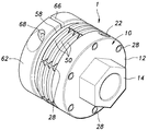
도 1은 본 발명에 따른 나사 체결구(너트)의 일 실시예의 사시도,
도 2는 본 발명의 실시예의 너트의 분해 사시도,
도 3은 본 발명의 실시예의 너트의 측면도,
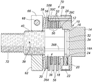
도 4는 도 3의 Ⅳ-Ⅳ선에 따른 단면도,
도 5는 도 4의 A로 표시된 부분의 확대 단면도,
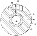
도 6은 도 3의 Ⅵ-Ⅵ선에 따른 단면도,
도 7은 본 발명에 따른 나사 체결구(볼트)의 대체 실시예의 단면도.1 is a perspective view of one embodiment of a screw fastener (nut) according to the present invention,
2 is an exploded perspective view of a nut according to an embodiment of the present invention,
3 is a side view of a nut of an embodiment of the present invention,
4 is a sectional view taken along the line IV-IV in Fig. 3,
FIG. 5 is an enlarged cross-sectional view of a portion indicated by A in FIG. 4,
6 is a sectional view taken along the line VI-VI in Fig. 3,
7 is a sectional view of an alternative embodiment of a threaded fastener (bolt) according to the present invention.
이하에서는 본 발명의 일 실시예의 체결 너트에 대해 도 1 내지 도 6을 참조하여 설명한다.Hereinafter, a lock nut according to an embodiment of the present invention will be described with reference to Figs. 1 to 6. Fig.
도시된 실시예의 너트(1)는 환상 주부(main part)(12)와 이 주부(12)의 축방향 단부(또는 도 4에 도시된 바로는 우측 단부)로부터 일체로 돌출하는 공구 맞물림 특징부(14)를 갖는 제 1 부재(10)를 포함한다.The
공구 맞물림 특징부(14)는 육각형 형상을 가짐으로써 스패너(도면에 도시되지 않음) 또는 다른 너트 맞물림 공구가 그 특징부(14)에 탈착 가능하게 부착될 수 있다. 주부(12)에는 공구 맞물림 특징부(14)에서 먼 쪽의 축방향 단부(또는 도 4에 도시된 바로는 좌측 단부)에서 개방되어 있는 중심 수용 구멍(16)이 형성되어 있다. 중심 수용 구멍(16)은 단면이 원형을 이루며, 그의 바닥측 단부에는 환상 숄더(annular shoulder)(16A)가 형성되어 있다.The tool
공구 맞물림 특징부(14)에서 먼 쪽의 주부(12)의 단부(도 4에 도시된 바로는 좌측 단부) 또는 중심 수용 구멍(16)의 개방 단부에 대응하는 단부는 반경방향 외측으로 연장되는 환상 단부면(18)을 형성한다. 환상 단부면(18)은 중심 축선에 대해 수직으로 연장되는 스러스트면으로서 기능한다.The end corresponding to the open end of the
6개의 축방향 관통 구멍(26)이 등간격으로 주부(12)의 주연부를 관통한다. 스프링 핀(28)의 단부(도 4에 도시된 바로는 우측 단부)가 각각의 관통 구멍(26)에 끼워지도록 가압된다. 따라서, 각각의 스프링 핀(28)은 그 일단부가 주부(12)에 고정되며, 후술하는 제 2 부재(30) 측(도 4에 도시된 바로는 좌측)을 향해 중심 축선과 평행하게 축방향으로 연장된다.Six axial through
제 2 부재(30)의 일 단부(도 4에 도시된 바로는 우측 단부)에 형성된 원통형 끼워맞춤 축부(32)는 중심 수용 구멍(16) 내에 끼워맞춤되며, 제 1 부재(10)의 중심 축선 주위로 회전 가능하게 환상 숄더(16A)에 맞닿는다. 원통형 끼워맞춤 축부(32)의 외주부에는 환상 둘레 홈(34)이 형성된다. 주부(12)에는 주부(12)를 반경방향으로 관통하는 나사 형성 구멍(20)이 형성된다. 보지 나사(22)가 나사 형성 구멍(20) 내에 나사 결합됨으로써, 보지 나사(22)의 자유 단부(24)에 형성된 기둥형 돌출부가 둘레 홈(34) 내에 슬라이딩 가능하게 수용된다. 이 보지 나사(22)는 제 1 부재(10)와 제 2 부재(30) 사이의 상대 회전 운동을 허용하면서도 이들 두 부재가 서로 멀어지는 축방향 운동을 방지하는 임의의 다른 보지 부재로 대체될 수도 있다.A cylindrical
따라서, 제 2 부재(30)는 제 1 부재(10)로부터 멀어지도록 당겨지는 것이 방지되면서도 제 1 부재(10)와 동축 상에 배치되어 상대 회전 가능하다. 제 2 부재(30)는 대체로 원통 형상이며, 끼워맞춤 축부(32)와 디스크 지지 축부(36)와 나사 형성 축부(38)를 축방향으로 그 순서대로 구비한다.Thus, the
나사 형성 축부(38)는 제 2 부재(30)의 다른 단부(도 4에 도시된 바로는 좌측 단부)에 형성되며, 외경이 디스크 지지 축부(36)보다 작다. 나사 형성 축부(38)의 외주면에는 수나사(40)가 형성되며, 그 내주면에는 체결 너트의 나사로서 기능하는 암나사(42)가 형성된다.The
디스크 지지 축부(36)는 끼워맞춤 축부(32)와 나사 형성 축부(38) 사이에 위치하며, 도 2에 도시된 바와 같이 공구 맞물림 특징부(14)와 맞물리는데 사용되는 것과 동일한 너트 회전 공구에 의해 탈착 가능하게 맞물릴 수 있는 육각형 축부(36A)로서 성형되어 있다. 육각형 축부(36A)의 형상은, 디스크 지지 축부(36)의 동심원의 일부를 이루는 원호부(36B)를 형성하도록 육각형 축부(36A)의 각 코너가 둥글게 되어 있는 점을 제외하고 공구 맞물림 특징부(14)와 실질적으로 동일하다.The disk
디스크 지지 축부(36)의 외주면에는 복수의 구동 디스크 부재(50) 및 복수의 피동 디스크 부재(52)가 축방향으로 슬라이딩 가능하게 그리고 축방향으로 서로 교호하도록 끼워맞춤되어 있다.A plurality of
각각의 구동 디스크 부재(50)에는 중심 구멍(50A)이 형성되어 있고, 각각의 구동 디스크 부재(50)는 중심 구멍(50A)을 거쳐서 디스크 지지 축부(36)의 원호부(36B)에 축방향으로 슬라이딩 가능하게 그리고 회전 가능하게 끼워맞춤된다. 이에 의해, 각각의 구동 디스크 부재(50)는 제 2 부재(30)에 대해 회전 가능하며 축방향으로 슬라이딩 가능하다.A
각 구동 디스크 부재(50)의 외주부에는 구동 디스크 부재(50)를 축방향으로 관통하는 6개의 구멍(50C)이 등간격으로 형성되어 있으며, 각각의 구멍(50C)은 반경방향 슬릿(50B)을 거쳐서 구동 디스크 부재(50)의 외측 에지에 연결된다. 각각의 구멍(50C)이 대응하는 스프링 핀(28)을 축방향으로 슬라이딩 가능하게 수용함으로써, 각각의 구동 디스크 부재(50)는 제 1 부재(10)에 대해 축방향으로 슬라이딩 가능하지만 회전은 불가능하게 된다. 즉, 각각의 구동 디스크 부재(50)는 제 1 부재(10)와 함께 회전한다.Six
각각의 피동 디스크 부재(52)에는 육각형 형상의 중심 구멍(52A)이 형성되어 있으며, 각각의 피동 디스크 부재(52)는 중심 구멍(52A)을 거쳐서 육각형 축부(36A)에 축방향으로 슬라이딩 가능하게 끼워맞춤됨으로써, 제 2 부재(30)에 대해 축방향으로 슬라이딩 가능하지만 회전은 불가능하게 된다. 즉, 각각의 피동 디스크 부재(52)는 제 2 부재(30)와 함께 회전한다.Each driven
피동 디스크 부재(52)의 외경이 구동 디스크 부재(50)의 외경보다 작으므로, 피동 디스크 부재(52)는 스프링 핀(28)으로부터 반경방향으로 이격되어 있어서 스프링 핀(28)을 방해하지 않는다.Since the outer diameter of the driven
구동 디스크 부재(50) 및 피동 디스크 부재(52)는 일반적인 강판 재료로 제조된다. 구동 디스크 부재(50)의 대향면과 맞물리는 피동 디스크 부재(52)의 면들에는, 도 5에 도시된 바와 같이, 스테인리스강과 같은, 구동 디스크 부재(50) 및 피동 디스크 부재(52)의 재료보다 내부식성이 높은(특히, 녹 방지 처리된) 재료로 제조된 박판(54)이 마련된다.The
피동 디스크 부재(52) 중 하나가 제 1 부재(10)의 환상 단부면(18)에 대해 축방향으로 가장 가까운 위치에 있고, 구동 디스크 부재(50) 중 하나가 그 다음에 배치된다. 나머지의 구동 디스크 부재(50) 및 피동 디스크 부재(52)는 교호하도록 배열되며, 나사 형성 축부(38)에 인접하는 측에는 프레셔 플레이트(pressure plate)(56) 및 환상 접시 스프링(dish spring)(58)이 그 순서대로 배열되어 있다.One of the driven
프레셔 플레이트(56)에는 육각형 중심 구멍(56A)이 형성되어 있어서, 프레셔 플레이트(56)가 육각형 중심 구멍(56A)을 거쳐서 육각형 축부(36A)에 축방향으로 슬라이딩 가능하게 끼워맞춤될 수 있다. 따라서, 피동 디스크 부재(52)와 유사하게, 프레셔 플레이트(56)도 제 2 부재(30)에 대해 축방향으로 슬라이딩 가능하며 회전은 불가능하다. 즉, 프레셔 플레이트(56)는 제 2 부재(30)와 함께 회전한다.A
프레셔 플레이트(56)도 일반적으로 강판 재료로 제조된다. 구동 디스크 부재(50)의 대향면과 맞물리는 프레셔 플레이트(56)의 표면에는, 도 5에 도시된 바와 같이, 스테인리스강과 같은, 프레셔 플레이트(56)의 재료보다 내부식성이 높은(특히, 녹 방지 처리된) 재료로 제조된 박판(54)이 마련된다.The
접시 스프링(58)에는 육각형 중심 구멍(58A)이 형성되어 있어서, 접시 스프링(58)이 중심 구멍(58A)을 거쳐서 디스크 지지 축부(36)의 원호부(36B)에 축방향으로 슬라이딩 가능하며 회전 가능하게 끼워맞춤될 수 있다. 이에 의해, 접시 스프링(58)은 제 2 부재(30)에 대해 회전 가능하며 축방향으로 슬라이딩 가능하다. 접시 스프링(58)은 구동 디스크 부재(50) 및 피동 디스크 부재(52)를 프레셔 플레이트(56)를 거쳐서 제 1 부재(10)의 환상 단부면(18)에 대해 가압한다.The
수나사(40)는 환상 스프링 리테이너(62)의 내주면에 형성된 암나사(64)와 나사식으로 맞물린다. 스프링 리테이너(62)가 수나사(40)에 나사 결합될 때, 스프링 리테이너(62)는 접시 스프링(58) 쪽으로 이동하여 접시 스프링에 프리로드를 가한다. 접시 스프링의 프리로드는 스프링 리테이너(62)를 대응 방향으로 회전시킴으로써 조절될 수 있다.The
스프링 리테이너(62)에는 스프링 리테이너(62)의 환형 형상에 있어서 반경방향 절결부를 제공하는 슬릿(66)이 형성되어 있다. 보지 나사(68)가 슬릿(66)을 가로질러서 스프링 리테이너(62) 내부를 통과하므로, 보지 나사(68)를 조임으로써 슬릿(66)의 폭을 좁힐 수도 있다. 보지 나사(68)에 의한 탄성 변형을 겪음으로써, 스프링 리테이너(62)는 수나사(40)의 임의의 소망 축방향 위치에서 나사 형성 축부(38)에 고정될 수 있다.The
따라서, 구동 디스크 부재(50), 피동 디스크 부재(52), 프레셔 플레이트(56), 접시 스프링(58) 및 스프링 리테이너(62)에 의해 제 1 부재(10)와 제 2 부재(30) 사이에 다중 플레이트 토크 리미터가 형성된다.Therefore, the
이 토크 리미터의 한계 토크(최대 체결 토크)는 접시 스프링(58)에 인가된 프리로드의 크기에 의해 결정된다. 제 1 부재(10)가 공구 맞물림 특징부(14)에 맞물리는 회전 공구(도면에 도시되지 않음)에 의해 한계 토크 미만의 토크로 회전할 때에는, 제 1 부재(10)의 회전이 구동 디스크 부재(50)와 피동 디스크 부재(52) 사이의 마찰 결합 및 스프링 핀(28)을 거쳐서 제 2 부재(30)에 전달됨으로써, 제 2 부재가 제 1 부재(10)와 함께 회전하게 된다.The limit torque (maximum tightening torque) of the torque limiter is determined by the size of the preload applied to the
볼트(도면에 도시되지 않음)의 수나사에의 암나사(42)의 나사 결합이 진행되어 너트(1)가 체결되는 경우, 제 1 부재(10)를 회전시키는데 필요한 토크가 증가한다. 이 토크가 토크 리미터의 한계 토크에 도달했을 때, 구동 디스크 부재(50)가 피동 디스크 부재(52)에 대해 미끄러지기 시작함으로써, 제 2 부재(30)가 제 1 부재(10)와 함께 회전하는 것이 중단된다. 그 결과, 과도한 체결 토크에 의해 제 1 부재(10)를 제 2 부재(30)에 대해 회전시키는 것을 방지할 수 있다.When the screwing of the
토크 리미터의 한계 토크는 스프링 리테이너(62)를 나사 형성 축부(38)에 대해 회전시킴으로써 연속적으로 변경할 수 있다.The limit torque of the torque limiter can be continuously changed by rotating the
이러한 토크 리미터에서, 구동 디스크 부재(50), 피동 디스크 부재(52) 및 프레셔 플레이트(56)의 마찰면들은 내부식성이 높은 박판에 의해 형성되므로, 부식으로 인한 마찰면의 고착을, 함유 금속(oil impreganted metal)과 같은 고가의 장치를 사용할 필요 없이 회피할 수 있다.In this torque limiter, since the friction surfaces of the
너트(1)에 통합된 토크 리미터는 복수의 디스크를 사용하고, 구동 디스크 부재(50)와 피동 디스크 부재(52) 사이의 마찰면의 직경을 증가시키는 일 없이 큰 마찰면적을 얻을 수 있어서, 토크 리미터의 외경을 증가시키거나 또는 접시 스프링(58)의 스프링 가압력을 증가시키는 일 없이 높은 한계 토크를 얻을 수 있다.The torque limiter incorporated in the
토크 전달을 위한 구동 디스크 부재(50)와 제 1 부재(10) 간의 결합은, 구동 디스크 부재(50)의 외주 에지에 형성되는 스플라인(spline) 및 외측 케이스의 내부벽에 형성되는 대응 스플라인 대신에, 구동 디스크 부재(50)의 외주부에 형성된 관통 구멍(50C) 및 그 안에 수용되는 스프링 핀(28)에 의해 얻어지며, 이는 토크 리미터의 외경을 최소화하는데 도움이 된다.The coupling between the
너트(1)는 후술하는 바와 같이 조립될 수 있다. 보지 나사(22)를 사용하여 제 2 부재(30)를 제 1 부재(10)에 접합한 상태에서, 구동 디스크 부재(50) 및 피동 디스크 부재(52)를 디스크 지지 축부(36)의 외주부에 교호하도록 끼워맞추고, 그 후, 프레셔 플레이트(56) 및 접시 스프링(58)을 끼워맞춘다. 스프링 리테이너(62)는 필요한 한계 토크를 얻을 때까지 수나사(40)에 나사 결합되며, 보지 나사(68)를 조임으로써 나사 형성 축부(38)에 단단하게 고정된다.The
너트 조립 과정의 대안예가 아래에 기술된다. 제 1 부재(10)가 제 2 부재(30)에 아직 접합되어 있지 않은 상태에서, 구동 디스크 부재(50) 및 피동 디스크 부재(52)를 디스크 지지 축부(36)의 외주부에 교호하도록 끼워맞추고, 그 후, 프레셔 플레이트(56) 및 접시 스프링(58)을 끼워맞춘다. 스프링 리테이너(62)는 필요한 한계 토크를 얻을 때까지 수나사(40)에 나사 결합되며, 보지 나사(68)를 조임으로써 나사 형성 축부(38)에 단단하게 고정된다. 이것을 서브 조립체로 취급하여, 제 2 부재(30)의 끼워맞춤 축부(32)를 제 1 부재의 중심 수용 구멍(16)에 끼워맞추고, 보지 나사(22)를 나사 형성 구멍(20)에 나사 결합함으로써 제 2 부재(30)를 제 1 부재에 접합한다.Alternative examples of the nut assembly process are described below. The
구동 디스크 부재(50), 피동 디스크 부재(52) 및 프레셔 플레이트(56)는 끼워맞춤 축부(32)에 인접한 디스크 지지 축부(36)의 일부의 외주부에 마련된 돌출부(36C)의 존재로 인해 서브 조립체로서 서로 접합되어 있는 동안에는 디스크 지지 축부(36)의 끼워맞춤 축부(32) 측으로부터 탈락하는 것이 방지된다. 제 1 부재(10)의 환상 주부(12)에는 돌출부(36C)를 수용하기 위한 리세스가 마련되며, 이에 의해, 환상 단부면(18)이 대향하는 피동 디스크 부재(52)에 평평한 접촉면을 제공한다.The
이러한 구성에 의하면, 제 2 부재(30)는 구동 디스크 부재(50), 피동 디스크 부재(52), 프레셔 플레이트(56), 접시 스프링(58) 및 스프링 리테이터(62)와 함께 결합되는 것에 의해 서브 조립체로서 취급될 수 있어서, 토크 리미터를 갖춘 너트(1)의 조립 효율을 향상시킬 수 있다.According to this configuration, the
너트(1)의 분해는 조립 과정의 역으로 실행함으로써 이루어질 수 있다. 구체적으로, 간단하게 보지 나사(22)를 체결 해제하는 것에 의해, 제 1 부재(10) 및 제 2 부재(30)가 쉽게 분리되므로 분해보수 효율도 향상될 수 있다.Disassembly of the
너트(1)의 암나사(42)가 부식으로 인해 고착되어, 너트(1)의 체결 해제에 필요한 토크가 한계 토크를 초과하는 경우, 제 1 부재(1)를 회전시켜도 토크 리미터의 미끄럼 작용으로 인해 제 2 부재(30)가 회전하지 않을 수도 있다.When the
이러한 경우, 보지 나사(68)를 체결 해제하고, 스프링 리테이너(62)를 풀러서, 구동 디스크 부재(50), 피동 디스크 부재(52), 프레셔 플레이트(56) 및 접시 스프링(58)을 나사 형성 축부(38) 쪽으로 이동시킨다. 그와 같이 육각형 축부(36A)를 노출시킴으로써, 렌치와 같은 공구가 육각형 축부(36A)에 맞물리게 하여, 그 공구로 제 2 부재(30), 나아가서는 너트(1)를 나사 풀림 방향으로 회전시킨다. 따라서, 육각형 축부(36A)는 피동 디스크 부재(52)의 회전을 방지하는 것과 제 2 부재(30)를 직접 회전시키기 위한 공구와 맞물리는 것의 2가지 목적을 제공한다.In this case, the holding
육각형 축부(36A)와 맞물리는 공구는 본질적으로 공구 맞물림 특징부(14)와 맞물리는데 사용되는 공구와 동일할 수도 있어서, 이들 목적을 위해 2개의 상이한 공구를 사용할 필요가 없다.The tool engaged with the
끼워맞춤 축부(32)의 단부의 외주부에 돌출부(36C)가 존재하지 않는 경우, 보지 나사(22)를 체결 해제시켜서 제 1 부재(10) 및 제 2 부재(30)를 분리하고 구동 디스크 부재(50) 및 피동 디스크 부재(52)를 끼워맞춤 축부(32) 측으로부터 제거함으로써, 간단하게 육각형 축부(36A)를 노출시킬 수 있다.When the projecting
본 발명을 구체화하는 볼트의 실시예에 대해 도 7을 참조하여 기술한다. 도 7에서, 도 4에 도시된 것과 대응하는 부분들은 유사한 도면부호를 부여하고, 그에 대한 반복 설명을 생략한다.An embodiment of a bolt embodying the present invention will be described with reference to Fig. In Fig. 7, the parts corresponding to those shown in Fig. 4 are given the same reference numerals, and repetitive explanations thereof are omitted.
본 실시예에서, 제 2 부재(30)는 중실 축부재로 이루어지며, 제 2 부재(30)에는, 암나사(42) 대신에, 체결 나사로서 볼트 형태의 수나사(72)가 제 2 부재(30)의 자유 단부에 형성되어 있다. 그 이외에, 본 실시예는 너트(1) 또는 제 1 실시예와 유사하다.In this embodiment, the
도시된 실시예의 볼트(70)는 너트(1)와 유사하게 작동하며, 유사한 장점을 제공한다.The
본 발명의 바람직한 실시예의 관점에서 본 발명에 대해 기술했지만, 당업자라면 본 발명의 범위를 벗어나지 않으면서 다양한 변화 및 변형이 가능함을 알 수 있다.Although the invention has been described in terms of a preferred embodiment thereof, it will be apparent to those skilled in the art that various changes and modifications can be made therein without departing from the scope of the invention.
예컨대, 공구 맞물림 특징부는 육각형 헤드에 한정되지 않으며, 직사각형 등의 다각형 헤드 또는 다각형 리세스로 이루어질 수도 있다.For example, the tool engagement feature is not limited to a hexagonal head, and may be a polygonal head, such as a rectangular, or a polygonal recess.
박판(54)은 각 구동 디스크 부재(50)의 양측면 또는 구동 디스크 부재(50) 및 피동 디스크 부재(52) 둘 모두의 양측면에 마련될 수도 있다. 사실상, 서로 맞물리는 구동 디스크 부재(50) 및 피동 디스크 부재(52)의 양측면 중 적어도 하나에 디스크 부재의 재료보다 내부식성이 높은 재료의 층이 마련되면 충분하다. 그러한 박판 또는 층의 사용은 본 발명에 필수적인 것은 아니다.The
제 1 부재(10)와 제 2 부재(30)를 서로 접합하는데 사용되는 보지 나사(22)는 하나가 아닐 수도 있으며, 복수의 보지 나사(22)가 둘레 방향을 따라 등간격으로 사용될 수도 있다. 또한, 제 1 부재 및 제 2 부재가 서로 회전 가능하면서도 이들 사이의 상대적인 축방향 운동을 방지하도록 제 1 부재 및 제 2 부재를 접합하기 위해, 원형 클립 또는 임의의 다른 탈착 가능한 보지 부재와 같은 다른 형태의 보지 부재를 사용할 수도 있다. 스프링 핀(28)은 중실 핀 또는 관형 핀으로 대체될 수도 있다. 접시 스프링(58)은 압축 코일 스프링 또는 고무 스프링으로 대체될 수도 있다.The holding screws 22 used to join the
제 1 부재(10)와 제 2 부재(30)를 서로 분리할 필요가 없는 경우, 보지 나사(22) 대신에, 스프링 핀 등의 핀 부재를 사용하여 제 1 부재(10)와 제 2 부재(30)를 상대 회전 가능하게 서로 접합할 수도 있다. 돌출부(36C)를 생략하고, 돌출부(36C) 대신에, 스냅 링 등을 탈착 가능하게 배치할 수도 있다.When it is not necessary to separate the
본 출원에서 언급한 종래 기술 문헌의 내용뿐만 아니라, 본 출원에 대한 파리 조약 우선권을 주장한 일본 기초 특허 출원의 내용도 참조에 의해 본 출원에 통합된다.The content of the Japanese Patent Application, which claims priority to the Paris Convention for the present application, as well as the contents of the prior art documents referred to in this application, are incorporated herein by reference.
10 : 제 1 부재
14 : 공구 맞물림 특징부
16 : 중심 수용 구멍
18 : 환상 단부면
20 : 나사 형성 구멍
22 : 보지 나사
28 : 스프링 핀
30 : 제 2 부재
32 : 끼워맞춤 축부
34 : 둘레 홈
36 : 디스크 지지 축부
36A : 육각형 축부
36B : 원호부
38 : 나사 형성 축부
40 : 수나사
42 : 암나사
50 : 구동 디스크 부재
50C : 관통 구멍
52 : 피동 디스크 부재
54 : 박판
56 : 프레셔 플레이트
58 : 접시 스프링
62 : 스프링 리테이너
66 : 슬릿
68 : 보지 나사
70 : 볼트
72 : 수나사10: first member 14: tool engaging feature
16: central receiving hole 18: annular end face
20: screw forming hole 22: holding screw
28: spring pin 30: second member
32: fitting shaft portion 34: peripheral groove
36: disk supporting
36B: arc portion 38: screw forming shaft portion
40: male thread 42: female thread
50: driving
52: driven disk member 54: thin plate
56: pressure plate 58: plate spring
62: spring retainer 66: slit
68: Retaining thread 70: Bolt
72: male thread
Claims (7)
축방향 단부에서 회전 공구(turning tool)와 맞물리는 공구 맞물림 특징부(tool engaging feature), 축방향 대향 단부에서 개방된 중심 수용 구멍(central receiving bore), 및 상기 중심 수용 구멍의 개방 단부를 둘러싸는 환상 단부면을 구비하는 제 1 부재;
상기 중심 수용 구멍 내에 회전 가능하게 수용되는 관형의 제 2 부재로서, 상기 제 2 부재는 외주부에 둘레 홈이 형성된 끼워맞춤 축부(fitting shaft portion)를 상기 제 2 부재의 축방향 단부에 갖고, 상기 제 2 부재의 축방향 대향 단부에 형성된 수나사를 구비하며, 상기 제 2 부재의 축방향 대향 단부에는 체결 나사가 추가로 마련되고, 상기 제 2 부재의 끼워맞춤 축부와 수나사 사이에는 디스크 지지 축부(disk supporting shaft portion)가 형성되는, 상기 제 2 부재;
상기 끼워맞춤 축부의 외주부의 둘레 홈 내에 부분적으로 수용되며, 상기 제 1 부재에 맞물리는 보지 부재(retaining member);
상기 제 1 부재에 고정되며, 상기 제 2 부재를 향해 축방향으로 연장되는 봉 부재;
상기 디스크 지지 축부의 외주면에 축방향으로 슬라이딩 가능하고 회전 가능하게 끼워맞춤되며, 상기 봉 부재가 축방향으로 관통하는 관통 구멍을 갖는 복수의 구동 디스크 부재;
상기 디스크 지지 축부의 외주면에 축방향으로 슬라이딩 가능하고 회전 불가능하게 상기 구동 디스크 부재와 축방향으로 교호하도록 끼워맞춤되는 복수의 피동 디스크 부재;
상기 구동 디스크 부재 및 상기 피동 디스크 부재를 상기 제 1 부재의 환상 단부면 쪽으로 가압하도록 상기 디스크 지지 축부의 외주면에 배치되는 스프링 부재; 및
상기 스프링 부재에 프리로드(preload)를 가하도록 상기 제 2 부재의 수나사에 나사식으로(threadably) 맞물리는 스프링 리테이너(spring retainer)를 포함하는
나사 체결구.In the screw fastener,
A tool engaging feature engaging the turning tool at the axial end, a central receiving bore that is open at the axially opposite end, and a tool engaging feature surrounding the open end of the center receiving opening A first member having an annular end face;
A second member having a fitting shaft portion in which a peripheral groove is formed in an outer peripheral portion of the second member at an axial end portion of the second member, Wherein the second member is provided with a male screw formed at an axially opposite end of the second member, and an axially opposite end of the second member is further provided with a fastening screw, and a disk supporting shaft portion is provided between the fitting shaft portion and the male screw of the second member. a shaft portion is formed on the first member;
A retaining member partially received in the peripheral groove of the outer peripheral portion of the fitting shaft portion and engaged with the first member;
A rod member fixed to the first member and extending axially toward the second member;
A plurality of drive disk members which are axially slidable and rotatably fitted to the outer circumferential surface of the disk support shaft portion and have through holes through which the rod members pass axially;
A plurality of driven disk members slidable in the axial direction on the outer circumferential surface of the disk support shaft portion and fitted to the drive disk member so as to be rotatable alternately in the axial direction;
A spring member disposed on an outer circumferential surface of the disk support shaft portion so as to press the drive disk member and the driven disk member toward the annular end surface of the first member; And
And a spring retainer threadably engaged with the male thread of the second member to apply a preload to the spring member
Screw fasteners.
상기 보지 부재는 상기 제 1 부재를 반경방향으로 관통하는 나사 형성 구멍 내에 나사 결합되는 보지 나사(retaining screw)를 포함하며, 상기 보지 나사는 상기 둘레 홈 내에 슬라이딩 가능하게 수용되는 자유 단부를 갖는
나사 체결구.The method according to claim 1,
Wherein the retaining member comprises a retaining screw threaded into a threaded hole radially through the first member, the retaining screw having a free end slidably received in the circumferential groove
Screw fasteners.
상기 공구 맞물림 특징부는 다각형 헤드를 포함하고, 상기 디스크 지지 축부는 상기 다각형 헤드와 동일한 공구에 맞물릴 수 있도록 상기 다각형 헤드와 등각인(conformal) 다각형 단면을 갖는 다각형 축부를 포함하며, 상기 피동 디스크 부재는 상기 다각형 축부에 끼워맞춤됨으로써 상기 제 2 부재에 의해 회전 불가능하게 고정되는
나사 체결구.The method according to claim 1,
Wherein the tool engagement feature comprises a polygonal head and the disk support shaft portion includes a polygonal shaft portion having a conformal polygonal cross section with the polygonal head so as to engage the same tool as the polygonal head, Is fixed to the polygonal shaft portion by the second member
Screw fasteners.
상기 구동 디스크 부재와 상기 피동 디스크 부재가 서로 접촉하는 적어도 하나의 표면에는 상기 구동 디스크 부재 및 상기 피동 디스크 부재의 재료보다 내부식성이 높은 박판 또는 코팅이 마련되는
나사 체결구.The method according to claim 1,
Wherein at least one surface on which the drive disk member and the driven disk member are in contact with each other is provided with a thin plate or coating having higher corrosion resistance than the materials of the drive disk member and the driven disk member
Screw fasteners.
상기 제 2 부재에 마련되는 상기 체결 나사는 상기 제 2 부재의 축방향 대향 단부에 형성된 중심 구멍 내에 형성되는 암나사를 포함하는
나사 체결구.The method according to claim 1,
Wherein the fastening screw provided on the second member includes a female screw formed in a center hole formed in an axially opposite end of the second member
Screw fasteners.
상기 제 2 부재에 마련되는 상기 체결 나사는 상기 제 2 부재의 축방향 대향 단부에 형성된 축방향 연장부에 형성되는 수나사를 포함하는
나사 체결구.The method according to claim 1,
Wherein the fastening screw provided on the second member includes a male screw formed on an axially extending portion formed on an axially opposite end of the second member
Screw fasteners.
상기 끼워맞춤 축부에 인접한 상기 디스크 지지 축부의 일부의 외주부에는 디스크 보지 특징부(disk retaining feature)가 마련되어, 상기 구동 디스크 부재 및 상기 피동 디스크 부재를 상기 끼워맞춤 축부 쪽으로 축방향 이동하지 못하도록 보지하는
나사 체결구.The method according to claim 1,
A disk retaining feature is provided on an outer circumferential portion of a part of the disk supporting shaft portion adjacent to the fitting shaft portion so as to prevent the driving disk member and the driven disk member from moving axially toward the fitting shaft portion
Screw fasteners.
Applications Claiming Priority (2)
| Application Number | Priority Date | Filing Date | Title |
|---|---|---|---|
| JP2014032675A JP6243750B2 (en) | 2014-02-24 | 2014-02-24 | Screw fastener |
| JPJP-P-2014-032675 | 2014-02-24 |
Publications (2)
| Publication Number | Publication Date |
|---|---|
| KR20150100531A true KR20150100531A (en) | 2015-09-02 |
| KR101909778B1 KR101909778B1 (en) | 2018-10-18 |
Family
ID=53782537
Family Applications (1)
| Application Number | Title | Priority Date | Filing Date |
|---|---|---|---|
| KR1020150025146A KR101909778B1 (en) | 2014-02-24 | 2015-02-23 | Screw fastener |
Country Status (6)
| Country | Link |
|---|---|
| US (1) | US9587665B2 (en) |
| JP (1) | JP6243750B2 (en) |
| KR (1) | KR101909778B1 (en) |
| CN (1) | CN104863949B (en) |
| DE (1) | DE102015002026B4 (en) |
| TW (1) | TWI603003B (en) |
Families Citing this family (7)
| Publication number | Priority date | Publication date | Assignee | Title |
|---|---|---|---|---|
| JP1529909S (en) * | 2014-10-28 | 2015-07-27 | ||
| JP1529984S (en) * | 2014-10-28 | 2015-07-27 | ||
| USD816192S1 (en) * | 2015-12-24 | 2018-04-24 | Miki Pulley Co., Ltd. | Shaft coupling hub |
| CN105840615A (en) * | 2016-04-26 | 2016-08-10 | 苏州昭沃五金科技有限公司 | Positioning connecting piece |
| DE102017219477A1 (en) * | 2017-11-02 | 2019-05-02 | Bayerische Motoren Werke Aktiengesellschaft | Assembly of a screw connection |
| DE102018003247A1 (en) * | 2018-04-20 | 2019-10-24 | Spieth-Maschinenelemente Gmbh & Co. Kg | The restraint |
| US11828319B1 (en) * | 2021-06-07 | 2023-11-28 | Daniel John Spriggel | Locknut |
Citations (7)
| Publication number | Priority date | Publication date | Assignee | Title |
|---|---|---|---|---|
| JPS56135529U (en) * | 1980-03-14 | 1981-10-14 | ||
| JPH01316558A (en) * | 1988-06-17 | 1989-12-21 | Mitsubishi Electric Corp | Device for limiting transmission of torque |
| EP0486002A1 (en) * | 1990-11-16 | 1992-05-20 | Shimano Inc. | Quick release apparatus for a bicycle |
| US5148652A (en) * | 1991-02-14 | 1992-09-22 | Herzog Kenneth J | Hand capper |
| JPH09226789A (en) * | 1996-02-24 | 1997-09-02 | Isao Takahashi | Collapsible tube having hole for hanging on hook |
| JPH1047326A (en) * | 1996-08-01 | 1998-02-17 | Fujitsu Ten Ltd | Screw with built-in torque limit mechanism |
| JP2000027886A (en) * | 1998-07-14 | 2000-01-25 | Fujikura Ltd | Torque limiting type rotary fastening device |
Family Cites Families (17)
| Publication number | Priority date | Publication date | Assignee | Title |
|---|---|---|---|---|
| US4074542A (en) * | 1976-11-03 | 1978-02-21 | Rockwell International Corporation | Coupling |
| US4205572A (en) * | 1978-08-29 | 1980-06-03 | Weiner Robert I | Saw blade retainer and kickback clutch assembly |
| US4249397A (en) | 1979-05-21 | 1981-02-10 | Resina Automatic Machinery Co. Inc. | Clutch construction for capping machine quill assembly |
| DE3045070A1 (en) * | 1980-11-29 | 1982-06-03 | Jean Walterscheid Gmbh, 5204 Lohmar | ADJUSTABLE FRICTION CLUTCH |
| DE3611617C1 (en) * | 1986-04-07 | 1992-12-10 | Ringspann Maurer Kg A | Device for releasably locking a bolt |
| US4793120A (en) * | 1987-12-24 | 1988-12-27 | Herzog Kenneth J | Clutch and cap disc assembly |
| GB9500509D0 (en) * | 1995-01-11 | 1995-03-01 | Gore W L & Ass Uk | Connector |
| GB2299641A (en) * | 1995-04-05 | 1996-10-09 | Hydraulic Tensioning Technolog | Hydraulic tensioning nut |
| US5546612A (en) * | 1995-04-24 | 1996-08-20 | Johnson; Oriz W. | Automatic domestic toilet seat lowering apparatus and disc brake assembly |
| US5653481A (en) * | 1996-02-09 | 1997-08-05 | United Dominion Industries, Inc. | Pipe clamp with live loading nut assembly |
| DE19848902A1 (en) * | 1997-11-20 | 1999-08-26 | Labs Holland Gmbh | Clamp |
| DE19819300A1 (en) * | 1998-04-30 | 1999-11-11 | Thomas Loeffler | Method and device for producing and testing screw connections |
| FR2852067B1 (en) * | 2003-03-07 | 2005-04-15 | Schneider Electric Ind Sas | SCREW TERMINAL DEBRAYABLE |
| FI6686U1 (en) * | 2005-03-21 | 2005-05-26 | Metso Paper Inc | Hydraulic clamping element |
| US8021093B2 (en) * | 2009-04-17 | 2011-09-20 | Flow-Rite Controls, Ltd. | Locking threaded fastener |
| DE102011003835A1 (en) * | 2011-02-09 | 2012-08-09 | Hilti Aktiengesellschaft | Torque-limited fastening device |
| CN203146543U (en) * | 2013-03-13 | 2013-08-21 | 山东威达机械股份有限公司 | Quick-assembly-and-disassembly nut |
-
2014
- 2014-02-24 JP JP2014032675A patent/JP6243750B2/en active Active
-
2015
- 2015-02-09 TW TW104104276A patent/TWI603003B/en active
- 2015-02-09 US US14/616,802 patent/US9587665B2/en active Active
- 2015-02-17 DE DE102015002026.9A patent/DE102015002026B4/en active Active
- 2015-02-17 CN CN201510086523.7A patent/CN104863949B/en active Active
- 2015-02-23 KR KR1020150025146A patent/KR101909778B1/en active IP Right Grant
Patent Citations (7)
| Publication number | Priority date | Publication date | Assignee | Title |
|---|---|---|---|---|
| JPS56135529U (en) * | 1980-03-14 | 1981-10-14 | ||
| JPH01316558A (en) * | 1988-06-17 | 1989-12-21 | Mitsubishi Electric Corp | Device for limiting transmission of torque |
| EP0486002A1 (en) * | 1990-11-16 | 1992-05-20 | Shimano Inc. | Quick release apparatus for a bicycle |
| US5148652A (en) * | 1991-02-14 | 1992-09-22 | Herzog Kenneth J | Hand capper |
| JPH09226789A (en) * | 1996-02-24 | 1997-09-02 | Isao Takahashi | Collapsible tube having hole for hanging on hook |
| JPH1047326A (en) * | 1996-08-01 | 1998-02-17 | Fujitsu Ten Ltd | Screw with built-in torque limit mechanism |
| JP2000027886A (en) * | 1998-07-14 | 2000-01-25 | Fujikura Ltd | Torque limiting type rotary fastening device |
Also Published As
| Publication number | Publication date |
|---|---|
| TWI603003B (en) | 2017-10-21 |
| CN104863949A (en) | 2015-08-26 |
| TW201540981A (en) | 2015-11-01 |
| DE102015002026A1 (en) | 2015-08-27 |
| US9587665B2 (en) | 2017-03-07 |
| DE102015002026B4 (en) | 2018-09-06 |
| US20150240856A1 (en) | 2015-08-27 |
| JP2015158221A (en) | 2015-09-03 |
| JP6243750B2 (en) | 2017-12-06 |
| KR101909778B1 (en) | 2018-10-18 |
| CN104863949B (en) | 2018-04-03 |
Similar Documents
| Publication | Publication Date | Title |
|---|---|---|
| KR101909778B1 (en) | Screw fastener | |
| TWI661909B (en) | Penetrating electric ratchet wrench and using method thereof | |
| US5383544A (en) | Force transmitting assembly | |
| US5180042A (en) | Torque transmission control device | |
| US8020472B2 (en) | Nut capturing socket assembly | |
| WO2016143551A1 (en) | Clutch device | |
| US20170335902A1 (en) | Torque Limiting Apparatus and Method | |
| TWI671163B (en) | Inertial rotation device | |
| JP2001328076A (en) | Torque transmitting tool | |
| KR20180014707A (en) | Friction clutch, and method of setting operating point of friction clutch | |
| US11697192B2 (en) | Tool for use in places with restricted access | |
| JP2015078744A (en) | Lock ring | |
| US20190178284A1 (en) | Interchangeable, debris insensitive and non-slipping reaction torque transfer system | |
| US9841045B2 (en) | Blind rivet fastener | |
| US20210187712A1 (en) | Torque socket tool | |
| JP2020536760A (en) | Clamping device and handheld power tool | |
| US11441593B2 (en) | Interchangeable, debris insensitive and non-slipping reaction torque transfer system | |
| US3871785A (en) | Nut locking devices | |
| US20150330436A1 (en) | Self-Locking Screwing Attachment Devices And Assemblies Provided With Same | |
| JPS6120736B2 (en) | ||
| JP5111346B2 (en) | Rotating body friction fastener set | |
| US4095685A (en) | Adjustable clutch assembly | |
| US9488232B1 (en) | Externally adjustable clutch | |
| JP6810705B2 (en) | Deformable screw assembly | |
| CN108453657B (en) | Penetration type electric ratchet wrench and using method thereof |
Legal Events
| Date | Code | Title | Description |
|---|---|---|---|
| A201 | Request for examination | ||
| E701 | Decision to grant or registration of patent right |