KR20150100007A - Secondary barrier installation structure and method - Google Patents
Secondary barrier installation structure and method Download PDFInfo
- Publication number
- KR20150100007A KR20150100007A KR1020140021265A KR20140021265A KR20150100007A KR 20150100007 A KR20150100007 A KR 20150100007A KR 1020140021265 A KR1020140021265 A KR 1020140021265A KR 20140021265 A KR20140021265 A KR 20140021265A KR 20150100007 A KR20150100007 A KR 20150100007A
- Authority
- KR
- South Korea
- Prior art keywords
- insulation panel
- barrier
- panel
- heat insulating
- panels
- Prior art date
Links
Images


Classifications
-
- B—PERFORMING OPERATIONS; TRANSPORTING
- B63—SHIPS OR OTHER WATERBORNE VESSELS; RELATED EQUIPMENT
- B63B—SHIPS OR OTHER WATERBORNE VESSELS; EQUIPMENT FOR SHIPPING
- B63B25/00—Load-accommodating arrangements, e.g. stowing, trimming; Vessels characterised thereby
- B63B25/02—Load-accommodating arrangements, e.g. stowing, trimming; Vessels characterised thereby for bulk goods
- B63B25/08—Load-accommodating arrangements, e.g. stowing, trimming; Vessels characterised thereby for bulk goods fluid
- B63B25/12—Load-accommodating arrangements, e.g. stowing, trimming; Vessels characterised thereby for bulk goods fluid closed
- B63B25/16—Load-accommodating arrangements, e.g. stowing, trimming; Vessels characterised thereby for bulk goods fluid closed heat-insulated
-
- B—PERFORMING OPERATIONS; TRANSPORTING
- B65—CONVEYING; PACKING; STORING; HANDLING THIN OR FILAMENTARY MATERIAL
- B65D—CONTAINERS FOR STORAGE OR TRANSPORT OF ARTICLES OR MATERIALS, e.g. BAGS, BARRELS, BOTTLES, BOXES, CANS, CARTONS, CRATES, DRUMS, JARS, TANKS, HOPPERS, FORWARDING CONTAINERS; ACCESSORIES, CLOSURES, OR FITTINGS THEREFOR; PACKAGING ELEMENTS; PACKAGES
- B65D90/00—Component parts, details or accessories for large containers
- B65D90/02—Wall construction
- B65D90/06—Coverings, e.g. for insulating purposes
-
- F—MECHANICAL ENGINEERING; LIGHTING; HEATING; WEAPONS; BLASTING
- F17—STORING OR DISTRIBUTING GASES OR LIQUIDS
- F17C—VESSELS FOR CONTAINING OR STORING COMPRESSED, LIQUEFIED OR SOLIDIFIED GASES; FIXED-CAPACITY GAS-HOLDERS; FILLING VESSELS WITH, OR DISCHARGING FROM VESSELS, COMPRESSED, LIQUEFIED, OR SOLIDIFIED GASES
- F17C3/00—Vessels not under pressure
- F17C3/02—Vessels not under pressure with provision for thermal insulation
- F17C3/04—Vessels not under pressure with provision for thermal insulation by insulating layers
Abstract
The present invention relates to a structure and a method for installing a secondary barrier, and more specifically, it is easy to install a heat insulating material in a gap of a secondary heat insulating panel, and a weld for welding a secondary barrier provided on the secondary heat insulating panel The present invention relates to a structure and a method for installing a secondary barrier capable of minimizing the time and effort required for installing a secondary barrier, thereby securing economical efficiency.
The present invention relates to a secondary insulation panel, which is installed on a plurality of inner surfaces of a hull; An insulator disposed in a gap between the secondary insulation panels; A secondary barrier formed on the secondary thermal insulation panel so as to be integrally formed with a corrugated portion positioned on the inserted thermal insulation material and a flat portion provided on each of the secondary thermal insulation panels on both sides of the inserted thermal insulation material; And a strip installed on the secondary insulation panel so as to be positioned at a boundary between the secondary walls, wherein the flat part is welded to a flat part of another secondary barrier, ≪ / RTI >
Description
The present invention relates to a secondary barrier installation structure and method, and more particularly, to a secondary barrier installation structure and a secondary barrier installation structure, And a barrier installation structure and method.
Natural gas is a fossil fuel containing methane as a main component and a small amount of ethane, propane, and the like, and has recently been regarded as a low-pollution energy source in various technical fields.
Natural gas is transported in a gaseous state through land or sea gas pipelines, or is transported to a remote location where it is stored in an LNG carrier in the form of liquefied natural gas (LNG). Liquefied natural gas is obtained by cooling natural gas at a cryogenic temperature (approximately -163 ° C), and its volume is reduced to approximately 1/600 of that of natural gas in a gaseous state, making it well suited for long distance transportation through the sea.
LNG RV, LNG FPSO, LNG FSRU, and other marine structures are equipped with cargo (storage tank) that can store and store liquefied natural gas. Since the boiling point of liquefied natural gas is about -163 ° C at atmospheric pressure, the liquefied natural gas hold is made of materials that can withstand extremely low temperatures such as aluminum steel, stainless steel and 35% nickel steel to safely store and store liquefied natural gas And is designed to be resistant to thermal stress and heat shrinkage, and to prevent heat penetration.
These storage tanks are classified into independent tanks and membrane types depending on whether the load of the cargo directly acts on the insulation. The membrane type storage tanks are GTT NO 96 type and TGZ MARK III type And the independent tank type storage tanks include MOSS type and IHI-SPB type.
The above NO 96 and MARK-III tank structures are described in U.S. Patent Nos. 6,035,795, 6,378,722, 5,586,513, and U.S. Patent Publication No. 2003-0000949, Korean Patent Laid-open Nos. 10-2000-0011347 and 10 -2000-0011346. Further, the structure of the independent tank type storage tank is described in Korean Patent No. 10-15063 and No. 10-305513.
Fig. 1 schematically shows a heat insulating structure of a NO 96 type storage tank.
The insulating structure of the NO 96 type storage tank is composed of a
In the case of the NO 96 type, since the
Fig. 2 schematically shows a heat insulation structure of the MARK-type storage tank.
The primary insulation wall of the MARK-III type storage tank is formed by laminating the
As a conventional technique for an LNG tank capable of storing and storing LNG that has been liquefied at a cryogenic temperature, there is a heat insulation structure of a liquefied natural gas cargo hold of Korean Patent Laid-Open No. 10-2012-0134596. A plurality of insulation panel parts coupled to the inner surface of the hull and formed to perform thermal insulation; A secondary barrier coupled with an upper portion of the plurality of insulation panel portions; A spacer plywood disposed on the upper surface of the secondary barrier; And a primary barrier coupled with the upper portion of the plurality of spacer pans.
In such a conventional technique, an insulation panel corresponding to a gap insulation is installed in an insulation panel, that is, a secondary insulation panel, because there is a gap due to mounting and manufacturing tolerances and insulation is required for the insulation panel. The installation method varies greatly depending on the membrane shape of the secondary barrier.
Also, in the prior art, it is necessary to separate and install the secondary barriers and then perform welding for them because it is difficult in the actual process to install the whole without installing the secondary barrier in order to install the insulator . At this time, the time and effort required for the installation of the secondary barrier vary greatly depending on how the secondary barrier composed of a flat part and a corrugation part is separated into a certain structure and how it is welded And particularly, as the number of welding lines for integrating the secondary barrier increases, it is uneconomical. Therefore, it has been necessary to find a way to enable the economical installation of the secondary barrier by reducing the welding line of the secondary barrier while enabling the installation of the insulator corresponding to the gap insulation between the secondary insulation panels.
It is an object of the present invention to solve the above-mentioned problems of the prior art, and it is an object of the present invention to provide a method of installing a heat insulating material in a gap of a secondary thermal insulating panel by minimizing a welding line for integrating a secondary wall, To reduce the time and effort required to ensure the economic efficiency.
According to an aspect of the present invention, there is provided a secondary insulation panel, An insulator disposed in a gap between the secondary insulation panels; A secondary barrier formed on the secondary thermal insulation panel so as to be integrally formed with a corrugated portion positioned on the inserted thermal insulation material and a flat portion provided on each of the secondary thermal insulation panels on both sides of the inserted thermal insulation material; And a strip installed on the secondary adiabatic panel so as to be positioned at a boundary between the secondary barriers, wherein the flat part is welded to the flat part of the other secondary barrier to provide a plurality of secondary barrier mounting structures.
According to another aspect of the present invention, there is provided a secondary insulation panel that is installed on a plurality of inner surfaces of a hull; An insertion heat insulating part integrally formed on a side of the secondary heat insulating panel so as to be positioned in a gap between the secondary heat insulating panels; A secondary barrier formed on the secondary thermal insulation panel so as to integrally form a corrugated portion positioned on the insertion heat insulating portion and a flat portion provided on each of the secondary thermal insulating panels on both sides of the inserted thermal insulating portion; And a strip installed on the secondary adiabatic panel so as to be positioned at a boundary between the secondary barriers, wherein the flat part is welded to the flat part of the other secondary barrier to provide a plurality of secondary barrier mounting structures.
The secondary barrier may be formed such that the flat portion extends to a central portion of the secondary thermal insulation panel.
The strip may be inserted into the secondary insulation panel to form the same surface as the secondary insulation panel.
The strip may be installed at the center of the secondary insulation panel.
The strip may be made of stainless steel.
According to another aspect of the present invention, there is provided a secondary insulation panel on which a strip for securing a secondary barrier is installed on the inner surface of a hull, and a corrugated portion positioned on the inserted heat insulating portion, A plurality of secondary walls integrally formed with the flat portions provided on the secondary insulation panels of the plurality of secondary walls are installed on the secondary insulation panel and the flat portions are welded to the flat portions of the other secondary walls, Lt; / RTI >
And an insulative thermal insulating material may be separately provided between the plurality of secondary insulating panels spaced apart from each other.
And an insertion heat insulating portion integrally formed on a side portion of the secondary heat insulating panel may be disposed in a gap between the secondary heat insulating panels.
The strip may be inserted into the secondary insulation panel to form the same surface as the secondary insulation panel, may be installed at the center of the secondary insulation panel, and may be made of stainless steel.
The step of connecting the plurality of secondary walls may extend the flat portion of the secondary barrier to the central portion of the secondary insulation panel.
According to the present invention, it is easy to install the insulator in the gap of the secondary insulation panel, the welding line for the integration of the secondary barrier provided on the secondary insulation panel can be minimized, and the installation of the secondary barrier It is possible to secure economical efficiency by reducing the time and effort required.
1 is a perspective view schematically showing a heat insulating structure of a NO 96 type storage tank;
2 is a perspective view schematically showing a heat insulating structure of a storage tank of a MARK-III type.
3 to 6 are sectional views sequentially showing a second barrier installation method according to the first embodiment of the present invention.
7 to 9 are sectional views sequentially showing a second barrier installation method according to a second embodiment of the present invention.
DETAILED DESCRIPTION OF THE PREFERRED EMBODIMENTS Hereinafter, preferred embodiments of the present invention will be described in detail with reference to the accompanying drawings. In addition, the following embodiments can be modified into various other forms, and the scope of the present invention is not limited to the following embodiments.
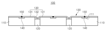
6 is a cross-sectional view showing a secondary barrier installation structure according to the first embodiment of the present invention.
As shown in FIG. 6, the secondary
The
A primary insulation panel and a primary barrier are sequentially stacked on the
The insertion
The
The
The
9 is a cross-sectional view showing a secondary barrier installation structure according to a second embodiment of the present invention.
9, the second
In the secondary
The insertion
3 to 6 are sectional views sequentially showing the secondary barrier installation method according to the first embodiment of the present invention. The installation method of the secondary
3 and 4, a plurality of
The
5 and 6, when the
7 to 9 are sectional views sequentially showing the second barrier installation method according to the second embodiment of the present invention. In the installation method of the second
7, by providing a plurality of secondary
The
8 and 9, when the
According to the present invention, it is easy to install the insulator in the gap of the secondary insulation panel and the welding line for the integration of the secondary barrier installed on the secondary insulation panel Thereby reducing the time and effort required for the installation of the secondary barrier, thereby securing economical efficiency.
It will be apparent to those skilled in the art that various modifications and variations can be made in the present invention without departing from the spirit and scope of the invention. It is.
110: secondary insulation panel 111: groove
120: Insertion insulation 130: Secondary barrier
131: flat part 132:
140: strip 150: welded part
210: secondary insulation panel 211: groove
220: insertion insulator 230: secondary barrier
231: flat part 232:
240: Strip 250: Weld
Claims (13)
An insulator disposed in a gap between the secondary insulation panels;
A secondary barrier formed on the secondary thermal insulation panel so as to be integrally formed with a corrugated portion positioned on the inserted thermal insulation material and a flat portion provided on each of the secondary thermal insulation panels on both sides of the inserted thermal insulation material; And
And a strip installed on the secondary insulation panel so as to be positioned at a boundary between the secondary walls,
And the plurality of flat portions are welded to the flat portions of the other secondary walls.
An insertion heat insulating part integrally formed on a side of the secondary heat insulating panel so as to be positioned in a gap between the secondary heat insulating panels;
A secondary barrier formed on the secondary thermal insulation panel so as to integrally form a corrugated portion positioned on the insertion heat insulating portion and a flat portion provided on each of the secondary thermal insulating panels on both sides of the inserted thermal insulating portion; And
And a strip installed on the secondary insulation panel so as to be positioned at a boundary between the secondary walls,
And the plurality of flat portions are welded to the flat portions of the other secondary walls.
Wherein the secondary barrier comprises:
Wherein the flat portion is formed to extend to a central portion of the secondary thermal insulation panel.
Wherein the strip comprises:
And a secondary barrier installation structure inserted into the secondary insulation panel to form the same surface as the secondary insulation panel.
Wherein the strip comprises:
And a second barrier installation structure provided at the center of the secondary insulation panel.
Wherein the strip comprises:
A secondary barrier installation structure made of stainless steel.
A plurality of secondary walls are integrally formed on the secondary thermal insulation panel, and a plurality of corrugation portions positioned on the insertion heat insulating portion and a plurality of flat portions integrally formed on the secondary thermal insulating panels on both sides of the insertion heat insulating portion,
And connecting the plurality of secondary walls by welding the flat portion to a flat portion of another secondary barrier.
Wherein a plurality of secondary insulation panels spaced apart from each other are separately installed between the secondary insulation panels.
Wherein the secondary insulation panel is provided with an insertion heat insulating portion integrally formed on a side portion of the secondary thermal insulating panel so as to be positioned in a gap between the secondary thermal insulating panels.
Wherein the strip comprises:
Wherein the secondary insulation panel is inserted into the secondary insulation panel to form the same surface as the secondary insulation panel.
Wherein the strip comprises:
Wherein the secondary barrier is installed at the center of the secondary insulation panel.
Wherein the strip comprises:
A method of installing a secondary barrier, made of stainless steel.
The step of connecting a plurality of secondary barriers comprises:
Wherein a flat portion of the secondary barrier extends to a central portion of the secondary insulation panel.
Priority Applications (1)
| Application Number | Priority Date | Filing Date | Title |
|---|---|---|---|
| KR1020140021265A KR20150100007A (en) | 2014-02-24 | 2014-02-24 | Secondary barrier installation structure and method |
Applications Claiming Priority (1)
| Application Number | Priority Date | Filing Date | Title |
|---|---|---|---|
| KR1020140021265A KR20150100007A (en) | 2014-02-24 | 2014-02-24 | Secondary barrier installation structure and method |
Publications (1)
| Publication Number | Publication Date |
|---|---|
| KR20150100007A true KR20150100007A (en) | 2015-09-02 |
Family
ID=54241802
Family Applications (1)
| Application Number | Title | Priority Date | Filing Date |
|---|---|---|---|
| KR1020140021265A KR20150100007A (en) | 2014-02-24 | 2014-02-24 | Secondary barrier installation structure and method |
Country Status (1)
| Country | Link |
|---|---|
| KR (1) | KR20150100007A (en) |
Cited By (1)
| Publication number | Priority date | Publication date | Assignee | Title |
|---|---|---|---|---|
| WO2018024982A1 (en) * | 2016-08-02 | 2018-02-08 | Gaztransport Et Technigaz | Impermeable wall structure |
-
2014
- 2014-02-24 KR KR1020140021265A patent/KR20150100007A/en not_active Application Discontinuation
Cited By (4)
| Publication number | Priority date | Publication date | Assignee | Title |
|---|---|---|---|---|
| WO2018024982A1 (en) * | 2016-08-02 | 2018-02-08 | Gaztransport Et Technigaz | Impermeable wall structure |
| FR3054871A1 (en) * | 2016-08-02 | 2018-02-09 | Gaztransport Et Technigaz | SEALED WALL STRUCTURE |
| CN109790958A (en) * | 2016-08-02 | 2019-05-21 | 气体运输技术公司 | Containment wall construction |
| CN109790958B (en) * | 2016-08-02 | 2021-09-07 | 气体运输技术公司 | Leakage-proof wall structure |
Similar Documents
| Publication | Publication Date | Title |
|---|---|---|
| JP6479221B2 (en) | Sealed heat insulation tank having a secondary sealed membrane provided with a corner arrangement with a corrugated metal sheet | |
| KR102209265B1 (en) | Sealed, thermally insulating vessel comprising a corner part | |
| JP2016511815A (en) | Sealed insulation walls for tanks for storing fluids | |
| KR20110046627A (en) | Insulation panel attachment structure of an independence type liquified gas tank and attachment method thereof | |
| US20170158291A1 (en) | Corner panel for ultra-low temperature fluid storage tank, and ultra-low temperature fluid thermal insulation system having same | |
| KR102048641B1 (en) | Vessels with insulated corner blocks provided with stress relief slots | |
| KR102387173B1 (en) | Insulation structure of 90 degree corner in liquefied gas cargo tank, and cargo tank having the insulation structure | |
| KR102535974B1 (en) | Heat insulation installation method for cryogenic liquid storage tank | |
| KR102535971B1 (en) | Insulation system of membraine type storage tank and membrain type storage tank | |
| KR101751839B1 (en) | Insulation system of membraine type storage tank and membrain type storage tank | |
| KR101686507B1 (en) | Lng storage tank | |
| KR101686506B1 (en) | Lng storage tank and insulation pannel thereof | |
| KR101567874B1 (en) | Connecting Structure And Method For Insulation System | |
| KR101713852B1 (en) | Secondary barrier installation structure and method | |
| KR20160004754A (en) | Lng storage tank and insulation pannel securing device thereof | |
| KR20160004756A (en) | Lng storage tank and insulation pannel securing device thereof | |
| KR20150082780A (en) | Insulation Structure For LNG Cargo Tank And Constructing Method Of The Same | |
| KR20150100007A (en) | Secondary barrier installation structure and method | |
| EP3733500B1 (en) | Membrane bonding structure and liquefied gas storage tank comprising same | |
| KR101680691B1 (en) | Cargo for liquefied gas and manufacturing method thereof | |
| KR101751840B1 (en) | Corner insulation wall of membraine type storage tank, membrain type storage tank comprising the same and insulation system of lng storage tank | |
| KR102525949B1 (en) | Insulation system of membraine type storage tank and membrain type storage tank | |
| KR20180092402A (en) | Insulation system of corner part in membrane type lng storage tank | |
| KR20200023478A (en) | Insulated closed tank with curved support strip | |
| KR20150045765A (en) | An insulation system for a cargo tank |
Legal Events
| Date | Code | Title | Description |
|---|---|---|---|
| A201 | Request for examination | ||
| E902 | Notification of reason for refusal | ||
| E902 | Notification of reason for refusal | ||
| E601 | Decision to refuse application |