KR20150097637A - Demodulation reference signal configuration and mapping method, channel estimation method and device - Google Patents
Demodulation reference signal configuration and mapping method, channel estimation method and device Download PDFInfo
- Publication number
- KR20150097637A KR20150097637A KR1020157018912A KR20157018912A KR20150097637A KR 20150097637 A KR20150097637 A KR 20150097637A KR 1020157018912 A KR1020157018912 A KR 1020157018912A KR 20157018912 A KR20157018912 A KR 20157018912A KR 20150097637 A KR20150097637 A KR 20150097637A
- Authority
- KR
- South Korea
- Prior art keywords
- dmrss
- ofdm symbols
- groups
- group
- prb pair
- Prior art date
Links
Images


Classifications
-
- H—ELECTRICITY
- H04—ELECTRIC COMMUNICATION TECHNIQUE
- H04W—WIRELESS COMMUNICATION NETWORKS
- H04W72/00—Local resource management
- H04W72/04—Wireless resource allocation
- H04W72/044—Wireless resource allocation based on the type of the allocated resource
- H04W72/0446—Resources in time domain, e.g. slots or frames
-
- H—ELECTRICITY
- H04—ELECTRIC COMMUNICATION TECHNIQUE
- H04L—TRANSMISSION OF DIGITAL INFORMATION, e.g. TELEGRAPHIC COMMUNICATION
- H04L5/00—Arrangements affording multiple use of the transmission path
- H04L5/003—Arrangements for allocating sub-channels of the transmission path
- H04L5/0048—Allocation of pilot signals, i.e. of signals known to the receiver
- H04L5/0051—Allocation of pilot signals, i.e. of signals known to the receiver of dedicated pilots, i.e. pilots destined for a single user or terminal
-
- H—ELECTRICITY
- H04—ELECTRIC COMMUNICATION TECHNIQUE
- H04L—TRANSMISSION OF DIGITAL INFORMATION, e.g. TELEGRAPHIC COMMUNICATION
- H04L5/00—Arrangements affording multiple use of the transmission path
- H04L5/0001—Arrangements for dividing the transmission path
- H04L5/0003—Two-dimensional division
- H04L5/0005—Time-frequency
- H04L5/0007—Time-frequency the frequencies being orthogonal, e.g. OFDM(A), DMT
Landscapes
- Engineering & Computer Science (AREA)
- Signal Processing (AREA)
- Computer Networks & Wireless Communication (AREA)
- Mobile Radio Communication Systems (AREA)
Abstract
본 발명의 일 실시예에서 제공된 것은 복조 기준 신호(DMRS) 구성 및 매핑 방법, 채널 추정 방법 및 장치이고, 방법은: 물리 자원 블록(PRB) 쌍 내에 4개의 직교 주파수 분할 다중(OFDM) 기호들을 통해 DMRS를 내포(bearing)하는 단계를 포함하고, 4개의 OFDM 기호들은 2개의 그룹으로 나뉘고, 각각의 그룹은 2개의 이웃하는 OFDM 기호들로 구성되고, OFDM 기호들의 2개의 그룹 사이의 거리는 5개의 OFDM 기호보다 크다. 본 발명의 실시예의 방법 및 장치는 LTE 고버전(출시 12 혹은 그 후 버전)내의 DMRS-기반 채널 추정 성능을 향상시킨다.Provided in one embodiment of the present invention is a demodulation reference signal (DMRS) configuration and mapping method, a channel estimation method and apparatus, the method comprising the steps of: providing four orthogonal frequency division multiplexing (OFDM) symbols in a physical resource block DMRS, wherein the four OFDM symbols are divided into two groups, each group consisting of two neighboring OFDM symbols, the distance between two groups of OFDM symbols being equal to five OFDM symbols It is bigger than the symbol. The method and apparatus of embodiments of the present invention improve the DMRS-based channel estimation performance within the LTE high version (Release 12 or later).
Description
본 발명은 통신 분야에 관한 것이고, 더 구체적으로는 복조 기준 신호들(demodulation reference signals)을 구성하고, 복조 기준 신호들을 매핑(mapping)하고, 채널 추정(channel estimation)을 수행하기 위한 방법 및 장치에 관한 것이다.The present invention relates to the field of communications, and more particularly to a method and apparatus for configuring demodulation reference signals, mapping demodulation reference signals, and performing channel estimation. .
LTE{롱-텀 에볼루션(long-term evolution)} 출시 8 내지 11에서, 각각의 다운링크 서브프레임(downlink subframe)은 현 다운링크 서브프레임 내의 스케줄링(scheduling) 또는 대응되는 업링크 서브프레임의 스케줄링을 가지는 UE(User Equipment)를 지시하고, 업링크 전송 전력(uplink transmission power)을 구성하고, SPS(semi-persistent scheduling) 전송을 활성화하거나 방출하는 데 사용되는 PDCCD(physical downlink control channel)를 운반할 것이다. PDCCH가 서브프레임 내의 앞의 첫번째 내지 네번째 기호로서 전송되고, 이에 점유되는 기호들의 숫자는 시스템의 대역폭과 하나의 서브프레임에 스케줄링된 UE들의 숫자에 의해 결정된다. PDSCH(physical downlink shared channel)와 다르게, PDCCH의 전송 자원은 RB(자원 블록)에 의해 나누어져 있지 않고, PDCCH 전송 유닛은 인터리버(interleaver)에 의해 전체 PDCCH 영역에 분산되어있다. PDCCH는 보통 셀-특정 기준 신호(cell-specific reference signal)(CRS)를 복조에 대한 기준 신호로서 취한다.LTE {long-term evolution} In
PDSCH는 상위 계층 시그널링(high-layer signaling) 또는 UE 데이터를 운반하는데 사용되고, 출시 9 이후의 출시에서는, TM8 및 TM9의 모드(mode)에서 전송된 PDSCH는 DMRS(demodulation reference signal)를 복조의 기준 신호로서 취한다. 한 PRB 쌍 내의 TDD(time division duplexing) 전송 모드에 있는 특별한 서브프레임 유형들 1,2,3,4,6,7 및 8이 아닌 서브프레임의 일반 DMRS의 분포가 도 1에 도시되어 있고, 여기에서 격자 부분의 OFDM{직교 주파수 분할 다중(orthogonal frequency division multiplexing)} 기호들이 PDCCH 전송 영역일 수 있고, 다른 OFDM 기호들은 PDSCH의 OFDM 기호들을 운반하기 위해 사용된다. 이러한 경우에, 기존 파일럿 패턴(pilot pattern)은 PDSCH 영역 내의 비교적 중간 지점에 위치한다. 기존 파일럿 패턴의 파일럿들에 기반하여 채널 추정이 수행되는 경우, 추정 결과의 오류는 비교적 작다.The PDSCH is used for carrying high-layer signaling or UE data. In the release after 9, the PDSCH transmitted in the mode of TM8 and TM9 transmits a demodulation reference signal (DMRS) . The distribution of generic DMRS in subframes other than the
새로운 캐리어 유형(new carrier type)(NCT)이 최신 LTE 출시인 출시 12에 도입될 것이다. NCT 캐리어에서, PDCCH는 ePDCCH(enhanced PDCCH)로 대체될 것이다. ePDCCH의 전송 방법은 PDSCH의 그것과 유사하고, 이 전송 방법의 전송 자원은 PRB 쌍들에 의해 나누어진다. NCT에서는 레거시(legacy) PDCCH가 더 이상 사용되지 않으므로, PDSCH들 또는 ePDCCH들을 운반하기 위한 각각의 PRB 쌍에 있는 자원들은 제1 OFDM 기호로부터 시작된다. NCT의 각각의 PRB 쌍 내의 데이터를 운반하는 모든 RE들(resource elements)은 DMRS에 기반하여 복조된다. 이러한 경우에, 기존 파일럿 패턴(도 1에 도시된 DMRS 패턴과 같은 것)이 전체 PRB 쌍의 오른쪽 위치에 위치되고, 이는 PRB 쌍 내의 여러 개의 앞의 OFDM 기호들의 채널 추정 품질의 열화를 야기할 수 있고, 이로 인해 이후의 복조와 디코딩(decoding)의 신뢰성에 영향을 준다.A new carrier type (NCT) will be introduced in
도 2는 이동 속도가 30km/h이고 SNR(signal to noise ratio)이 20dB이고 수신-전송 안테나가 2*2이고 랭크(rank)가 2일 때 하나의 PRB 쌍 내의 OFDM 기호들의 일련번호와 함께 달라지는 ETU(extended typical urban) 채널 모드의 채널 추정의 오류의 곡선을 제공한다. 오류가 시간 영역을 따라 비교적 많이 달라지고, 가장 왼쪽 3개의 OFDM 기호들 내의 채널 추정의 오류가 다른 OFDM 기호들에 비해 명백히 커지는 것을 도 2로부터 볼 수 있다.2 is a graph showing the relationship between the number of OFDM symbols in one PRB pair and the number of OFDM symbols in a PRB pair when the transmission speed is 30 km / h, the signal to noise ratio (SNR) is 20 dB, Provides a curve of error in channel estimation of ETU (extended typical urban) channel mode. It can be seen from FIG. 2 that the error is relatively much changed along the time domain and the error of the channel estimation in the leftmost three OFDM symbols becomes apparent compared to the other OFDM symbols.
배경기술의 위의 설명은 그저 본 발명의 명백하고 완전한 설명을 위해, 기술분야에 숙련된 자들의 용이한 이해를 위해 제공된다는 것에 주의해야 한다. 그리고 위의 기술적 해결책이 본 발명의 배경기술에 설명되어 있다고 해서 기술분야에 숙련된 자들에게 공지된 것이라고 이해되어서는 안 된다. It should be noted that the above description of the background art is provided for an easy understanding of those skilled in the art for a clear and complete description of the present invention. And should not be understood as being known to those skilled in the art since the above technical solutions are described in the background of the invention.
본 발명의 실시예들의 목적은 LTE들의 최신 출시들(출시 12 또는 그 이상) 내의 DMRS에 기반한 채널 추정의 성능을 향상시키기 위해 DMRS들을 구성하고, DMRS들을 매핑하고, 채널 추정을 수행하는 것을 위한 방법 및 장치를 제공하는 것이다.An object of embodiments of the present invention is to provide a method for configuring DMRSs, mapping DMRSs, and performing channel estimation to improve the performance of channel estimation based on DMRS in the latest releases of LTEs (
본 발명의 실시예들의 제1 태양에 따르면, 복조 기준 신호들을 구성하기 위한 방법이 제공되고, 방법은:According to a first aspect of embodiments of the present invention, a method is provided for constructing demodulation reference signals, the method comprising:
하나의 물리 자원 블록(PRB) 쌍 내의 4개의 직교 주파수 분할 다중(OFDM) 기호들에 의해 운반되는 복조 기준 신호들(DMRS들)을 구성하는 단계 - 4개의 OFDM 기호들은 두 그룹으로 나뉘고, 각각의 그룹은 두 이웃하는 OFDM 기호로 구성되고, OFDM 기호들의 두 그룹 사이의 거리는 5개의 OFDM 기호보다 더 큼 - 를 포함한다.Configuring demodulation reference signals (DMRSs) carried by four orthogonal frequency division multiplexing (OFDM) symbols in one physical resource block (PRB) pair, the four OFDM symbols being divided into two groups, A group consists of two neighboring OFDM symbols, and the distance between two groups of OFDM symbols is greater than five OFDM symbols.
본 발명의 실시예의 제2 태양에 따르면, 복조 기준 신호를 매핑하기 위한 방법이 제공되고, 방법은:According to a second aspect of an embodiment of the present invention, a method is provided for mapping a demodulation reference signal, the method comprising:
제1 태양에서 설명된 바와 같은 복조 기준 신호들을 구성하기 위한 방법에 따라 LTE 시스템을 위한 PRB 쌍의 복조 기준 신호들을 구성하는 단계; 및Configuring demodulation reference signals of a PRB pair for an LTE system according to a method for constructing demodulation reference signals as described in the first aspect; And
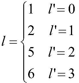
이하의 수학식:The following formula:
![]()
![]()
에 따라 구성된 복조 기준 신호들에 자원 매핑을 수행하는 단계를 포함하고, 여기에서And performing resource mapping on the demodulation reference signals constructed according to Equation

이고, 여기에서, ![]()
![]()
![]()
![]()
![]()
![]()
![]()
![]()
![]()
![]()
![]()
![]()
![]()
![]()
![]()
![]()
![]()
![]()
![]()
![]()
![]()
![]()
![]()
![]()
![]()
![]()
![]()
![]()


이다.to be.
본 발명의 실시예들의 제3 태양에 따르면, 복조 기준 신호들을 구성하기 위한 방법이 제공되고, 방법은:According to a third aspect of embodiments of the present invention, a method is provided for constructing demodulation reference signals, the method comprising:
각각의 PRB 쌍 내의 DMRS들의 6개보다 적은 그룹을 구성하는 단계 - DMRS들의 그룹의 각각은 DMRS들을 운반하는 2개의 RE들로 구성되고, DMRS들을 운반하는 2개의 RE들은 동일한 서브캐리어에 위치되고 두 이웃하는 OFDM 기호들을 점유함 - 를 포함한다.Configuring less than six groups of DMRSs in each PRB pair, each of the groups of DMRSs comprising two REs carrying DMRSs, two REs carrying DMRSs are located on the same subcarrier, Occupying neighboring OFDM symbols.
본 발명의 제4 태양에 따르면, 복조 기준 신호들을 매핑하기 위한 방법이 제공되고,According to a fourth aspect of the present invention there is provided a method for mapping demodulation reference signals,
제3 태양에 설명된 대로 복조 기준 신호들을 구성하기 위한 방법에 따라 LTE 시스템을 위한 PRB 쌍의 복조 기준 신호들을 구성하는 단계; 및Configuring demodulation reference signals of the PRB pair for the LTE system according to a method for constructing demodulation reference signals as described in the third aspect; And
이하의 수학식:The following formula:
![]()
![]()
에 따라 구성된 복조 기준 신호들 상에 자원 매핑을 수행하는 단계를 포함하고, 여기에서,And performing resource mapping on the demodulation reference signals constructed according to Equation

이고, 여기에서, ![]()
![]()
![]()
![]()
![]()
![]()
![]()
![]()
![]()
![]()
![]()
![]()
![]()
![]()
![]()
![]()
![]()
![]()
![]()
![]()
![]()
![]()
![]()
![]()
![]()
![]()
![]()
![]()
![]()
![]()
![]()
![]()


![]()
![]()


이다.to be.
본 발명의 실시예들의 제5 태양에 따르면, DMRS들을 구성하는 데 적용할 수 있는 eNB가 제공되고, eNB는:According to a fifth aspect of embodiments of the present invention, there is provided an eNB applicable to constructing DMRSs, the eNB comprising:
하나의 PRB 쌍 내의 4개의 OFDM 기호들에 의해 운반되는 DMRS들을 구성하도록 구성된 구성 유닛 - 4개의 OFDM 기호들은 두 그룹으로 나뉘고, 각각의 그룹은 두 이웃하는 OFDM 기호로 구성되고, OFDM 기호들의 두 그룹 사이의 거리는 5개의 OFDM 기호보다 더 큼 - 을 포함한다.A configuration unit configured to configure DMRSs carried by four OFDM symbols in one PRB pair, the four OFDM symbols being divided into two groups, each group consisting of two neighboring OFDM symbols, two groups of OFDM symbols Is greater than the five OFDM symbols.
본 발명의 실시예들의 제6 태양에 따르면, DMRS들을 매핑하는 데 적용할 수 있는 eNB가 제공되고, eNB는:According to a sixth aspect of embodiments of the present invention, there is provided an eNB applicable to mapping DMRSs, the eNB comprising:
제1 태양에서 설명된 대로 복조 기준 신호들을 구성하기 위한 방법에 따라 LTE 시스템을 위한 PRB 쌍의 복조 기준 신호들을 구성하도록 구성된 구성 유닛; 및A configuration unit configured to configure demodulation reference signals of a PRB pair for an LTE system according to a method for constructing demodulation reference signals as described in the first aspect; And
이하의 수학식:The following formula:
![]()
![]()
에 따라 구성된 복조 기준 신호 상에 자원 매핑을 수행하도록 구성된 매핑 유닛을 포함하고, 여기에서,And a mapping unit configured to perform resource mapping on the demodulation reference signal configured according to the mapping unit,

이고, 여기에서, ![]()
![]()
![]()
![]()
![]()
![]()
![]()
![]()
![]()
![]()
![]()
![]()
![]()
![]()
![]()
![]()
![]()
![]()
![]()
![]()
![]()
![]()
![]()
![]()
![]()
![]()
![]()
![]()


이다.to be.
본 발명의 실시예들의 제7 태양에 따르면, DMRS들을 구성하는 데 적용할 수 있는 eNB가 제공되고, eNB는:According to a seventh aspect of embodiments of the present invention, there is provided an eNB applicable for configuring DMRSs, the eNB comprising:
각각의 PRB 쌍 내의 DMRS들의 6개보다 적은 그룹을 구성하도록 구성된 구성 유닛 - DMRS들의 그룹의 각각은 DMRS들을 운반하는 2개의 RE들로 구성되고, DMRS들을 운반하는 2개의 RE들은 동일한 서브캐리어에 위치되고 두 이웃하는 OFDM 기호들을 점유함 - 을 포함한다.Each of the groups of configuration units configured to configure less than six groups of DMRSs in each PRB pair is comprised of two REs carrying DMRSs and two REs carrying DMRSs are located on the same subcarrier And occupies two neighboring OFDM symbols.
본 발명의 실시예들의 제8 태양에 따르면, DMRS들을 매핑하는 데 적용할 수 있는 eNB가 제공되고, eNB는:According to an eighth aspect of embodiments of the present invention, there is provided an eNB applicable to map DMRSs, the eNB comprising:
제3 태양에 설명된 대로 복조 기준 신호들을 구성하기 위한 방법에 따라 LTE 시스템을 위한 PRB 쌍의 복조 기준 신호들을 구성하도록 구성된 구성 유닛; 및A configuration unit configured to configure demodulation reference signals of a PRB pair for an LTE system according to a method for constructing demodulation reference signals as described in the third aspect; And
이하의 수학식:The following formula:
![]()
![]()
에 따라 구성된 복조 기준 신호들 상에 자원 매핑을 수행하도록 구성된 매핑 유닛을 포함하고, 여기에서,And a mapping unit configured to perform a resource mapping on the demodulation reference signals constructed according to Equation

이고, 여기에서, ![]()
![]()
![]()
![]()
![]()
![]()
![]()
![]()
![]()
![]()
![]()
![]()
![]()
![]()
![]()
![]()
![]()
![]()
![]()
![]()
![]()
![]()
![]()
![]()
![]()
![]()
![]()
![]()
![]()
![]()
![]()
![]()


![]()
![]()


이다.to be.
본 발명의 실시예들의 제9 태양에 따르면, 채널 추정을 수행하기 위한 방법이 제공되고, 방법은:According to a ninth aspect of embodiments of the present invention, there is provided a method for performing channel estimation, the method comprising:
제1 또는 제3 태양에 설명된 것과 같은 방법에 따라 구성된 DMRS들의 위치에 따라, 수신된 신호로부터 DMRS들을 추출하는 단계;Extracting the DMRSs from the received signal according to the location of the constructed DMRSs according to the method as described in the first or third aspect;
eNB에 의해 구성된 DMRS들에 따라 DMRS 시퀀스를 생성하는 단계; 및generating a DMRS sequence according to the DMRSs configured by the eNB; And
생성된 DMRS 시퀀스와 추출된 DMRS들에 따라 전송에서 수신된 신호들에 의해 통과되는 채널 상에 채널 추정을 수행하는 단계를 포함한다.And performing channel estimation on the channel that is passed by the signals received in the transmission in accordance with the generated DMRS sequence and the extracted DMRSs.
본 발명의 실시예들의 제10 태양에 따르면, 사용자 장비(UE)가 제공되고, 사용자 장비는:According to a tenth aspect of embodiments of the present invention, a user equipment (UE) is provided, the user equipment comprising:
제1 또는 제3 태양에 설명된 것과 같은 방법에 따라 구성된 DMRS들의 위치에 따라, 수신된 신호로부터 DMRS들을 추출하도록 구성된 추출 유닛;An extraction unit configured to extract DMRSs from the received signal according to the location of the DMRSs configured according to the method as described in the first or third aspect;
eNB에 의해 구성된 DMRS들에 따라 DMRS 시퀀스를 생성하도록 구성된 생성 유닛; 및a generating unit configured to generate a DMRS sequence according to the DMRSs configured by the eNB; And
생성된 DMRS 시퀀스와 추출된 DMRS들에 따라 전송에서 수신된 신호들에 의해 통과되는 채널 상에 채널 추정을 수행하도록 구성된 채널 추정 유닛을 포함한다.And a channel estimation unit configured to perform channel estimation on the channel that is passed by the signals received in the transmission in accordance with the generated DMRS sequence and the extracted DMRSs.
본 발명의 실시예들의 제11 태양에 따르면, 제5 태양 또는 제6 태양 또는 제7 태양 또는 제8 태양에 설명된 것과 같은 eNB 및 제10 태양에 설명된 것과 같은 UE를 포함하는 통신 시스템이 제공된다.According to an eleventh aspect of embodiments of the present invention, there is provided a communication system including an eNB as described in the fifth or sixth or seventh or eighth aspect and a UE as described in the tenth aspect do.
본 발명의 실시예는 컴퓨터-판독가능한 프로그램을 더 제공하고, 프로그램이 eNB에서 실행될 때, 프로그램은 컴퓨터가 제2 태양 또는 제4 태양에서 설명된 복조 기준 신호들을 매핑하기 위한 방법 또는 제1 태양 또는 제3 태양에서 설명된 복조 기준 신호들을 구성하기 위한 방법을 eNB에서 실행하는 것을 가능하게 한다.An embodiment of the present invention further provides a computer-readable program, and when the program is executed in an eNB, the program causes the computer to perform a method or a method for mapping the demodulation reference signals described in the second or fourth aspect, Enables the eNB to implement a method for constructing the demodulation reference signals described in the third aspect.
본 발명의 실시예는 컴퓨터-판독가능한 프로그램이 저장된 저장 매체를 더 제공하고, 컴퓨터-판독가능한 프로그램은 컴퓨터가 제2 태양 또는 제4 태양에서 설명된 복조 기준 신호들을 매핑하기 위한 방법 또는 제1 태양 또는 제3 태양에서 설명된 복조 기준 신호들을 구성하기 위한 방법을 eNB에서 실행하는 것을 가능하게 한다.An embodiment of the present invention further provides a storage medium in which a computer-readable program is stored, and the computer-readable program causes the computer to perform the method for mapping the demodulation reference signals described in the second or fourth aspect, Or the method for constructing the demodulation reference signals described in the third aspect in the eNB.
본 발명의 실시예는 컴퓨터-판독가능한 프로그램을 더 제공하고, 프로그램이 단말 장비에서 실행될 때, 프로그램은 컴퓨터가 제9 태양에서 설명된 대로 채널 추정을 수행하기 위한 방법을 단말 장비에서 실행하는 것을 가능하게 한다.Embodiments of the present invention further provide a computer-readable program that when executed on a terminal equipment, the program enables the computer to perform on the terminal equipment a method for performing channel estimation as described in the ninth aspect .
본 발명의 실시예는 컴퓨터-판독가능한 프로그램이 저장된 저장 매체를 더 제공하고, 컴퓨터-판독가능한 프로그램은 컴퓨터가 제9 태양에서 설명된 대로 채널 추정을 수행하기 위한 방법을 단말 장비에서 실행하는 것을 가능하게 한다.An embodiment of the present invention further provides a storage medium in which a computer-readable program is stored, and the computer-readable program enables the computer to execute in a terminal equipment a method for performing channel estimation as described in the ninth aspect .
본 발명의 실시예들의 장점은 본 발명의 실시예들의 방법 및 장치와 함께라면, LTE의 최신 출시들(출시 12 또는 그 이상) 내의 DMRS들에 기반한 채널 추정의 성능이 향상될 수 있다는 점에 존재한다.It is an advantage of embodiments of the present invention that, along with the methods and apparatus of embodiments of the present invention, the performance of channel estimation based on DMRSs in the latest releases of LTE (
이하의 설명과 도면들을 참조하여, 본 발명의 구체적인 실시예들은 자세히 개시되어있고, 본 발명의 원리와 사용 방식이 지시되어 있다. 본 발명의 실시예들의 범위는 그에 한정되지 않는다는 것이 이해되어야 한다. 본 발명의 실시예들은 첨부된 청구항들에 관한 범위 내에 많은 대안들, 수정들 및 동등물들을 포함한다.DETAILED DESCRIPTION OF THE PREFERRED EMBODIMENTS Reference will now be made in detail to the preferred embodiments of the present invention, examples of which are illustrated in the accompanying drawings, wherein like reference numerals refer to the like elements throughout. It is to be understood that the scope of the embodiments of the present invention is not limited thereto. The embodiments of the invention include many alternatives, modifications and equivalents within the scope of the appended claims.
일 실시예에 관해 도시 및/또는 설명된 특성들은 하나 이상의 다른 실시예들에서 동일하거나 유사한 방식 및/또는 다른 실시예들의 특성과 조합되어 또는 그 대신에 사용될 수 있다.The features shown and / or described in connection with one embodiment may be used in combination or in lieu of features in the same or similar manner and / or in other embodiments in one or more other embodiments.
용어들 "포함하고/포함되고"는 이 상세한 설명에서 사용되었을 때에는 명시된 특성들, 정수들, 단계들 또는 구성요소들의 존재를 특정하는 것으로 받아들여지나, 하나 이상의 기타 특성들, 정수들, 단계들, 구성요소들 또는 그들의 그룹들의 존재를 배제하지 않는다. The terms " comprising / included " when used in this detailed description are taken to specify the presence of stated features, integers, steps or components, but not limitative of the presence of one or more other characteristics, integers, , Does not exclude the presence of elements or groups thereof.
본 발명의 많은 태양은 이하의 도면들을 참조하여 더 잘 이해될 수 있다. 도면들의 구성요소들은 꼭 축척에 맞는 것은 아니고, 그 대신에 본 발명의 원리들을 명백히 도시하는 데에 중점을 두고 있다. 본 발명의 몇몇 부분들을 설명하고 도시하는 것을 용이하기 위해, 도면들의 대응되는 부분들은 크기가 감소되거나 과장될 수 있다. 본 발명의 일 도면 또는 실시예에 묘사된 요소들 및 특성들은 하나 이상의 추가 도면 또는 실시예들에 묘사된 요소들 및 특성들과 조합될 수 있다. 추가로, 도면에서, 유사한 참조 번호들은 여러 도면들 전체에서 대응되는 부분들을 지칭하고, 하나보다 더 많은 실시예들에서 비슷하거나 유사한 부분들을 지칭하는 데 사용될 수 있다.
도 1은 하나의 PRB 쌍 내의 기존 DMRS들의 분포의 개략도이다.
도 2는 하나의 PRB 쌍 내의 OFDM 기호들의 일련번호에 따라 변하는 채널 추정의 오류의 곡선이다.
도 3은 본 발명의 실시예 1의 복조 기준 신호들을 구성하기 위한 방법의 흐름도이다.
도 4a 내지 4e는 실시예 1의 방법에 따라 DMRS들을 구성하는 것의 분포의 개략도들이다.
도 5는 도 1에 도시된 DMRS들 및 도 4c에 도시된 DMRS들의 시뮬레이션 결과의 개략도이다.
도 6은 본 발명의 실시예 2의 복조 기준 신호들을 매핑하기 위한 방법의 흐름도이다.
도 7은 본 발명의 실시예 3의 복조 기준 신호들을 구성하기 위한 방법의 흐름도이다.
도 8은 도 1에 대응되는 DMRS들의 분포의 패턴 위치의 개략도이다.
도 9a 내지 9e는 동일한 주파수 영역 위치들의 DMRS들의 임의의 2개의 그룹이 제거되는 실시예 4의 방법에 따라 구성된 DMRS들의 분포의 개략도들이다.
도 10a 내지 10d는 대각선 방향으로 가장 바깥쪽인 DMRS들의 2개의 그룹이 제거되는 실시예 4의 방법에 따라 구성된 DMRS들의 분포의 개략도들이다.
도 11a 내지 11d는 DMRS들의 3개의 그룹이 지그재그(zigzag) 방식으로 제거되는 실시예 4의 방법에 따라 구성된 DMRS들의 분포의 개략도들이다.
도 12는 DMRS들이 주파수 영역 밀도를 낮춤으로 인해 구성된 본 발명의 다른 실시예에 따른 DMRS들의 분포의 개략도이다.
도 13은 DMRS들이 시간 영역 밀도를 낮춤으로 인해 구성된 본 발명의 다른 실시예에 따른 DMRS들의 분포의 개략도이다.
도 14는 본 발명의 실시예 4의 복조 기준 신호들을 매핑하기 위한 방법의 흐름도이다.
도 15는 본 발명의 실시예 5의 eNB의 구조의 개략도이다.
도 16은 본 발명의 실시예 6의 eNB의 구조의 개략도이다.
도 17은 본 발명의 실시예 7의 eNB의 구조의 개략도이다.
도 18은 본 발명의 실시예 8의 eNB의 구조의 개략도이다.
도 19는 본 발명의 일 실시예의 채널 추정을 수행하기 위한 방법의 흐름도이다.
도 20은 본 발명의 실시예의 UE의 구조의 개략도이다.Many aspects of the invention may be better understood with reference to the following drawings. The components of the figures are not necessarily to scale, emphasis instead being placed upon clearly illustrating the principles of the invention. To facilitate describing and illustrating some portions of the present invention, corresponding portions of the figures may be reduced in size or exaggerated. The elements and features depicted in one figure or embodiment of the present invention may be combined with elements and features described in one or more further figures or embodiments. Further, in the figures, like reference numerals refer to corresponding parts throughout the several views and may be used to refer to similar or similar parts in more than one embodiment.
1 is a schematic diagram of the distribution of existing DMRSs in one PRB pair.
Figure 2 is a curve of error in channel estimation that varies according to the sequence number of the OFDM symbols in one PRB pair.
3 is a flowchart of a method for constructing demodulation reference signals according to the first embodiment of the present invention.
Figures 4A-4E are schematic diagrams of the distribution of configuring DMRSs according to the method of
5 is a schematic diagram of the simulation results of the DMRSs shown in FIG. 1 and the DMRSs shown in FIG. 4C.
6 is a flowchart of a method for mapping the demodulation reference signals of the second embodiment of the present invention.
7 is a flowchart of a method for constructing demodulation reference signals according to a third embodiment of the present invention.
8 is a schematic diagram of the pattern position of the distribution of DMRSs corresponding to FIG.
Figures 9A-9E are schematic diagrams of the distribution of DMRSs constructed in accordance with the method of
Figs. 10a to 10d are schematic diagrams of the distribution of DMRSs constructed according to the method of
Figures 11A-11D are schematic diagrams of the distribution of DMRSs constructed in accordance with the method of
Figure 12 is a schematic representation of the distribution of DMRSs according to another embodiment of the present invention in which the DMRSs are constructed due to the lowering of the frequency domain density.
Figure 13 is a schematic representation of the distribution of DMRSs according to another embodiment of the present invention in which the DMRSs are constructed due to the lowering of the time domain density.
14 is a flowchart of a method for mapping the demodulation reference signals of the fourth embodiment of the present invention.
15 is a schematic view of the structure of an eNB according to
16 is a schematic view of the structure of an eNB according to
17 is a schematic view of the structure of an eNB according to
18 is a schematic view of the structure of the eNB of the eighth embodiment of the present invention.
19 is a flowchart of a method for performing channel estimation in an embodiment of the present invention.
20 is a schematic diagram of the structure of a UE in an embodiment of the present invention.
본 발명의 실시예들의 앞서 언급된 및 기타 특성들은 도면 및 이하의 설명을 참조하여 명백해질 것이다. 이러한 실시예들은 오직 예시적이고, 본 발명을 한정하는 것을 의도하지 않는다. 본 발명의 구현의 원리와 모드들이 기술분야의 숙련자들에 의해 쉽게 이해되기 위해서, 본 발명의 구현들의 모드들은 출시 12에 뉴-타입 캐리어들(new-type carriers)이 도입된 후에 DMRS들을 매핑하고 구성하는 것을 예시로 들어 설명될 것이다. 그러나, 본 발명은 위의 출시에서의 DMRS들의 위의 구성 및 매핑에 한정되지 않고, DMRS들인 기준 신호들의 구성 또는 매핑에도 한정되지 않고, 기준 신호들 및 기타 기준 신호들의 구성 및 매핑에 관련된 기타 시스템에도 적용가능하다.The foregoing and other features of the embodiments of the present invention will become apparent with reference to the drawings and the following description. These embodiments are illustrative only and are not intended to limit the invention. In order for the principles and modes of implementation of the present invention to be readily understood by those skilled in the art, the modes of implementation of the present invention map DMRSs after introducing new-type carriers into
실시예 1Example 1
본 발명의 실시예는 복조 기준 신호들을 구성하기 위한 방법을 제공한다. 도 3은 이 방법의 흐름도이다. 도 3에 도시된 바와 같이, 방법은,Embodiments of the present invention provide a method for constructing demodulation reference signals. Figure 3 is a flow chart of this method. As shown in Figure 3,
단계 301: 하나의 물리 자원 블록(PRB) 쌍 내의 4개의 직교 주파수 분할 다중(OFDM) 기호들에 의해 운반되는 복조 기준 신호들(DMRS들)을 구성하는 단계 - 4개의 OFDM 기호들은 두 그룹으로 나누어지고, 각각의 그룹들은 2개의 이웃하는 OFDM 기호들로 구성되고, OFDM 기호들의 2개의 그룹들 사이의 거리는 5개의 OFDM 기호보다 더 큼 - 를 포함한다.Step 301: constructing demodulation reference signals (DMRSs) carried by four orthogonal frequency division multiplexing (OFDM) symbols in one physical resource block (PRB) pair - the four OFDM symbols are divided into two groups Each group consisting of two neighboring OFDM symbols, and the distance between two groups of OFDM symbols being greater than five OFDM symbols.
도 4a 내지 4e는 이 실시예의 방법에 따라 DMRS를 구성하는 단계에서 하나의 PRB 쌍 내의 DMRS들의 분포의 개략도이다.4A to 4E are schematic diagrams of the distribution of DMRSs in one PRB pair in the step of configuring the DMRS according to the method of this embodiment.
이 실시예의 일 구현에서, 도 4a 및 4b에 도시된 바와 같이, OFDM 기호들의 2개의 그룹의 위치는 PRB 쌍을 구성하는 2개의 슬롯의 경계에 대해 대칭적이다.In one implementation of this embodiment, as shown in Figs. 4A and 4B, the positions of the two groups of OFDM symbols are symmetric about the boundaries of the two slots making up the PRB pair.
도 4a를 참조하면, OFDM 기호들의 제1 그룹은 제1 슬롯의 앞의 두 OFDM 기호들이고, OFDM 기호들의 제2 그룹은 제2 슬롯의 뒤의 두 OFDM 기호들이다.Referring to FIG. 4A, the first group of OFDM symbols are the two OFDM symbols preceding the first slot, and the second group of OFDM symbols are the two OFDM symbols after the second slot.
도 4b를 참조하면, OFDM 기호들의 제1 그룹은 제1 슬롯의 제2 및 제3 OFDM 기호들이고, OFDM 기호들의 제2 그룹은 제2 슬롯의 제5 및 제6 OFDM 기호들이다.Referring to FIG. 4B, the first group of OFDM symbols are the second and third OFDM symbols of the first slot, and the second group of OFDM symbols are the fifth and sixth OFDM symbols of the second slot.
이 실시예의 다른 구현에서, 도 4c 내지 4e에 도시된 바와 같이, OFDM 기호들의 2개의 그룹의 위치는 PRB 쌍을 구성하는 2개의 슬롯의 경계에 대해 비대칭적이다.In another implementation of this embodiment, as shown in Figures 4C-4E, the positions of the two groups of OFDM symbols are asymmetric about the boundaries of the two slots making up the PRB pair.
도 4c를 참조하면, OFDM 기호들의 제1 그룹은 제1 슬롯의 제2 및 제3 OFDM 기호들이고, OFDM 기호들의 제2 그룹은 제2 슬롯의 뒤의 두 OFDM 기호들이다.Referring to FIG. 4C, the first group of OFDM symbols are the second and third OFDM symbols of the first slot, and the second group of OFDM symbols are the two OFDM symbols after the second slot.
도 4d를 참조하면, OFDM 기호들의 제1 그룹은 제1 슬롯의 제3 및 제4 OFDM 기호들이고, OFDM 기호들의 제2 그룹은 제2 슬롯의 뒤의 두 OFDM 기호들이다.Referring to FIG. 4D, the first group of OFDM symbols are the third and fourth OFDM symbols of the first slot, and the second group of OFDM symbols are the two OFDM symbols after the second slot.
도 4e를 참조하면, OFDM 기호들의 제1 그룹은 제1 슬롯의 제4 및 제5 OFDM 기호들이고, OFDM 기호들의 제2 그룹은 제2 슬롯의 뒤의 두 OFDM 기호들이다.Referring to FIG. 4E, the first group of OFDM symbols are the fourth and fifth OFDM symbols of the first slot, and the second group of OFDM symbols are the two OFDM symbols after the second slot.
이 실시예에서, 주파수 영역 내의 DMRS들의 위치는 한정되지 않는다. 바람직한 실시예에서, 주파수 영역 내의 그들의 위치는 표준에서의 그들의 위치와 동일하다. 예를 들어, 하나 이상의 포트들에 대응되는 DMRS들이 코드 분할 체계(code division scheme)를 사용함으로써 물리 자원 블록 쌍(PRB 쌍)의 주파수 영역 내의 제1, 제6 및 제11 자원 요소들(RE들)을 점유하거나, 하나 이상의 포트에 대응되는 DMRS들이 코드 분할 체계를 사용함으로써 PRB 쌍의 주파수 영역 내의 제2, 제7 및 제12 RE들을 점유한다. 도 4a 내지 4e에서 도시된 바와 같이, 주파수 영역 내의 제1, 제6, 제11 RE들을 점유하고 있는 DMRS들은 포트 7, 8, 11 및 13에 대응되고, 주파수 영역 내의 제2, 제7, 제12 RE들을 점유하고 있는 DMRS들은 포트 9, 10, 12 및 14에 대응된다. 또는, 주파수 영역 내의 제1, 제6, 제11 RE들을 점유하고 있는 DMRS들은 포트 9, 10, 12 및 14에 대응되고, 주파수 영역 내의 제2, 제7, 제12 RE들을 점유하고 있는 DMRS들은 포트 7, 8, 11 및 13에 대응된다(도시되지 않음). 다른 실시예에서는, 주파수 영역 내의 그들의 위치는 표준에서의 그들의 위치와 상이할 수 있다. 예를 들어, 그들은 표준에 기반하여 주파수 영역 밀도를 낮출 수 있다. 예를 들어, 동일한 주파수 영역 위치의 임의의 2개의 그룹이 주파수 영역 내의 DMRS들의 6개의 그룹들로부터 제거될 수 있거나, 대각선 방향으로 가장 바깥의 2개의 그룹이 주파수 영역 내의 DMRS들의 6개의 그룹들로부터 제거될 수 있거나, 3개의 그룹이 주파수 영역 내의 DMRS들의 6개의 그룹들로부터 지그재그 방식으로 제거될 수 있고, 이는 이하의 실시예에서 자세히 설명될 것이다. In this embodiment, the location of the DMRSs in the frequency domain is not limited. In a preferred embodiment, their position in the frequency domain is the same as their position in the standard. For example, the DMRSs corresponding to one or more ports can be divided into first, sixth and eleventh resource elements (REs) in the frequency domain of a physical resource block pair (PRB pair) by using a code division scheme. Or occupies the second, seventh and twelfth REs in the frequency domain of the PRB pair by using the code division scheme with the DMRSs corresponding to one or more ports. 4A to 4E, DMRSs occupying the first, sixth and eleventh REs in the frequency domain correspond to
도 5는 도 1에 도시된 DMRS들의 분포 및 도 4c에 도시된 DMRS들의 분포의 시뮬레이션 결과의 개략도이다. 기존 방법을 사용하여 구성된 DMRS들에 비해, 본 발명의 실시예의 방법을 사용하여 구성된 DMRS들이 채널 추정의 성능을 매우 향상시킨다는 것을 도 5로부터 볼 수 있다.FIG. 5 is a schematic diagram of simulation results of the distribution of the DMRSs shown in FIG. 1 and the distribution of the DMRSs shown in FIG. 4C. It can be seen from FIG. 5 that the DMRSs constructed using the method of the present invention, compared to the DMRSs constructed using the existing method, greatly improve the performance of the channel estimation.
본 발명의 실시예의 방법과 함께, LTE의 최신 출시들(출시 12 또는 그 이상)에서의 DMRS들에 기반한 채널 추정의 성능은 향상될 수 있다.With the method of embodiments of the present invention, the performance of channel estimation based on DMRSs in the latest releases of LTE (
실시예 2Example 2
본 발명의 실시예는 복조 기준 신호들을 매핑하기 위한 방법을 더 제공한다. 이 방법은 실시예 1의 DMRS들의 구성에 기반한 것이다. 실시예 1의 방법에 따라서 DMRS들을 구성하며, 기존 표준 방법에 동일한 방법을 사용하여 DMRS 시퀀스가 생성될 수 있다; 그러나, DMRS들을 매핑하기 위한 방법은 기존 표준과 상이하다. 도 6은 이 실시예의 DMRS들을 매핑하기 위한 방법의 흐름도이다. 도 6을 참조하면, 방법은,Embodiments of the present invention further provide a method for mapping demodulation reference signals. This method is based on the configuration of the DMRSs of Example 1. The DMRS sequences can be generated using the same method as the existing standard method, constructing the DMRSs according to the method of Example 1; However, the method for mapping the DMRSs is different from the existing standard. 6 is a flow chart of a method for mapping DMRSs in this embodiment. Referring to Figure 6,
단계 601: LTE 시스템을 위한 PRB 쌍의 복조 기준 신호들을 구성하는 단계 - DMRS들은 실시예 1의 방법을 사용하여 구성되고, 그 내용은 여기에 포함되고 더 이상 여기에서 설명되지 않을 것임 -;Step 601: Constructing the demodulation reference signals of the PRB pair for the LTE system - the DMRSs are configured using the method of
단계 602: 이하의 수학식:Step 602: < RTI ID = 0.0 >
![]()
![]()
에 따라, 구성된 복조 기준 신호들에 자원 매핑을 수행하는 단계, Performing resource mapping on the configured demodulation reference signals
를 포함한다..
여기에서,From here,

![]()
![]()
![]()
![]()


이고;ego;
위의 수학식의 기호들의 정의는 3GPP TS36.211의 Section 6.10.3의 그것들과 동일하고, 여기서 더 이상 설명되지 않을 것이다. 예를 들어, ![]()
![]()
![]()
![]()
![]()
![]()
![]()
![]()
![]()
![]()
![]()
![]()
![]()
![]()
![]()
![]()
![]()
![]()
![]()
![]()
![]()
![]()
![]()
![]()
![]()
![]()
![]()
![]()
도 4a에 도시된 DMRS들의 분포에 대응하여,Corresponding to the distribution of the DMRSs shown in Figure 4A,


![]()
![]()

실시예 1의 방법을 사용하여 DMRS들을 구성하고 이 실시예의 방법을 사용하여 DMRS들을 매핑함으로써, LTE의 최신 출시들(출시 12 또는 그 이상)에서의 DMRS들에 기반한 채널 추정의 성능이 향상될 수 있다.By configuring the DMRSs using the method of
실시예 3Example 3
본 발명의 실시예는 복조 기준 신호들을 구성하기 위한 방법을 더 제공한다. 실시예 1의 방법과는 상이하게, 이 실시예에서는, 각각의 PRB 쌍 내의 DMRS들의 그룹의 개수는 6보다 작고; DMRS들의 각각의 그룹의 패턴은 동일한 서브캐리어 내에 위치하고 두 이웃하는 OFDM 기호들을 점유하는 2개의 RE들로 구성된다.Embodiments of the present invention further provide a method for constructing demodulation reference signals. Unlike the method of
도 7은 본 발명의 실시예 3의 복조 기준 신호들을 구성하기 위한 방법의 흐름도이다. 도 7을 참조하여, 방법은,7 is a flowchart of a method for constructing demodulation reference signals according to a third embodiment of the present invention. Referring to Figure 7,
단계 701: 각각의 PRB 쌍 내에 DMRS들의 6개보다 적은 그룹을 구성하는 단계 - DMRS들의 각각의 그룹은 DMRS들을 운반하는 2개의 RE들로 구성되고, DMRS들을 운반하는 2개의 RE들은 동일한 서브캐리어 내에 위치하고 두 이웃하는 OFDM 기호들을 점유함 - 를 포함한다. Step 701: Constructing less than six groups of DMRSs in each PRB pair - each group of DMRSs consists of two REs carrying DMRSs, and two REs carrying DMRSs are in the same subcarrier And occupies two neighboring OFDM symbols.
일 실시예에서, 하나 이상의 포트들에 대응되는 DMRS들이 코드 분할 체계를 사용함으로써 주파수 영역 내의 제1, 제6 및/또는 제11 RE들을 점유하거나, 하나 이상의 포트에 대응되는 DMRS들이 코드 분할 체계를 사용함으로써 주파수 영역 내의 제2, 제7 및/또는 제12 RE들을 점유한다. In one embodiment, the DMRSs corresponding to one or more ports occupy the first, sixth and / or eleventh REs in the frequency domain by using a code division scheme, or the DMRSs corresponding to one or more ports are assigned a code division scheme Occupies the second, seventh and / or twelfth REs in the frequency domain.
이 실시예에서, 시간 영역에서의 DMRS들의 위치는 한정되어 있지 않다. 예를 들어, 그들은 도 1에 도시된 기존 표준 내의 DMRS들의 시간 영역 위치에 기반할 수 있고, 또한 도 4a 내지 4e에 도시된 이 실시예의 DMRS들의 시간 영역 위치에 기반할 수 있다. 편리함을 위해, 도 8에 표시된 문자 A 내지 F가 도 1 또는 도 4a 내지 4e에 도시된 하나 또는 몇몇 포트들에 대응되는 각각 DMRS들의 6개의 그룹과 대응된다는 것 및 이 실시예의 방법이 도 1에 도시된 기존 표준 내의 DMRS들의 시간 영역 위치에 기반한다는 것을 예시로 하여 설명한다.In this embodiment, the location of the DMRSs in the time domain is not limited. For example, they may be based on the time domain location of the DMRSs in the existing standard shown in FIG. 1 and may also be based on the time domain location of the DMRSs of this embodiment shown in FIGS. 4A-4E. For convenience, the letters A through F shown in FIG. 8 correspond to six groups of respective DMRSs corresponding to one or several ports shown in FIG. 1 or 4A through 4E, and the method of this embodiment is shown in FIG. Is based on the time domain location of the DMRSs in the existing standard shown.
이 실시예의 구현에서, 위의 DMRS들의 6개의 그룹은 4개의 그룹으로 감소될 수 있다, 즉 각각의 PRB 쌍 내에 DMRS들의 4개의 그룹을 구성할 수 있다; 바람직하게는, 시간 영역 내의 DMRS들의 4개의 그룹의 위치와 밀도는 일정하게 유지되고(즉, 기존 DMRS 패턴들의 시간 영역 위치에 기반하거나, 실시예 1의 구현들의 DMRS 패턴들의 시간 영역 위치에 기반함), DMRS들의 4개의 그룹들은 주파수 영역 내의 위치들의 3개의 그룹 중 임의의 2개의 그룹에서 구성된다; 즉, 주파수 영역의 DMRS들의 6개의 그룹으로부터 동일한 주파수 영역 위치의 임의의 2개의 그룹을 제거한다. 예를 들어, 그룹 A 및 그룹 B가 제거되거나, 그룹 C 및 그룹 D가 제거되거나, 그룹 E 및 그룹 F가 제거된다. In an implementation of this embodiment, the six groups of the above DMRSs may be reduced to four groups, i.e. they may constitute four groups of DMRSs within each PRB pair; Preferably, the positions and densities of the four groups of DMRSs in the time domain remain constant (i.e., based on the time domain location of existing DMRS patterns or based on the time domain location of the DMRS patterns of implementations of embodiment 1) ), The four groups of DMRSs are organized in any two of the three groups of positions in the frequency domain; That is, any two groups of the same frequency domain location are removed from the six groups of DMRSs in the frequency domain. For example, group A and group B are removed, group C and group D are removed, or group E and group F are removed.
도 9a 내지 9e는 이 구현의 방법에 따라 구성된 후의 DMRS들의 개략도이다.Figures 9a-9e are schematic diagrams of DMRSs constructed according to the method of this implementation.
도 9a에 도시된 바와 같이, 이 구현에서, 포트 7, 8, 11 및 13에 대응되는 DMRS들의 그룹 A, B, C 및 D의 DMRS들의 위치와 밀도는 일정하게 유지되는 반면, 포트 7, 8, 11, 13에 대응되는 DMRS들의 그룹 E 및 F는 제거되고; 동시에, 포트 9, 10, 12 및 14에 대응되는 DMRS들의 그룹 A, B, C 및 D의 DMRS들의 위치와 밀도는 일정하게 유지되는 반면, 포트 9, 10, 12 및 14에 대응되는 DMRS들의 그룹 E 및 F는 제거된다. 9A, in this implementation, the location and density of the DMRSs of groups A, B, C, and D of the DMRSs corresponding to
도 9b에 도시된 바와 같이, 이 구현에서, 포트 7, 8, 11 및 13에 대응되는 DMRS들의 그룹 A, B, E 및 F의 DMRS들의 위치와 밀도는 일정하게 유지되는 반면, 포트 7, 8, 11, 13에 대응되는 DMRS들의 그룹 C 및 D는 제거되고; 동시에, 포트 9, 10, 12 및 14에 대응되는 DMRS들의 그룹 A, B, E 및 F의 DMRS들의 위치와 밀도는 일정하게 유지되는 반면, 포트 9, 10, 12 및 14에 대응되는 DMRS들의 그룹 C 및 D는 제거된다.9B, in this implementation, the location and density of the DMRSs of groups A, B, E, and F of DMRSs corresponding to
도 9c에 도시된 바와 같이, 이 구현에서, 포트 7, 8, 11 및 13에 대응되는 DMRS들의 그룹 C, D, E 및 F의 DMRS들의 위치와 밀도는 일정하게 유지되는 반면, 포트 7, 8, 11, 13에 대응되는 DMRS들의 그룹 A 및 B는 제거되고; 동시에, 포트 9, 10, 12 및 14에 대응되는 DMRS들의 그룹 C, D, E 및 F의 DMRS들의 위치와 밀도는 일정하게 유지되는 반면, 포트 9, 10, 12 및 14에 대응되는 DMRS들의 그룹 A 및 B는 제거된다.9C, in this implementation, the location and density of the DMRSs of groups C, D, E, and F of DMRSs corresponding to
도 9d에 도시된 바와 같이, 이 구현에서, 포트 7, 8, 11 및 13에 대응되는 DMRS들의 그룹 A, B, C 및 D의 DMRS들의 위치와 밀도는 일정하게 유지되는 반면, 포트 7, 8, 11, 13에 대응되는 DMRS들의 그룹 E 및 F는 제거되고; 동시에, 포트 9, 10, 12 및 14에 대응되는 DMRS들의 그룹 C, D, E 및 F의 DMRS들의 위치와 밀도는 일정하게 유지되는 반면, 포트 9, 10, 12 및 14에 대응되는 DMRS들의 그룹 A 및 B는 제거된다.9D, in this implementation, the location and density of the DMRSs of groups A, B, C, and D of the DMRSs corresponding to
도 9e에서 도시된 바와 같이, 이 구현에서, 포트 7, 8, 11 및 13에 대응되는 DMRS들의 그룹 C, D, E 및 F의 DMRS들의 위치와 밀도는 일정하게 유지되는 반면, 포트 7, 8, 11, 13에 대응되는 DMRS들의 그룹 A 및 B는 제거되고; 동시에, 포트 9, 10, 12 및 14에 대응되는 DMRS들의 그룹 A, B, C 및 D의 DMRS들의 위치와 밀도는 일정하게 유지되는 반면, 포트 9, 10, 12 및 14에 대응되는 DMRS들의 그룹 E 및 F는 제거된다. 9E, in this implementation, the location and density of the DMRSs of groups C, D, E, and F of DMRSs corresponding to
이 실시예의 다른 구현에서, 위의 DMRS들의 6개의 그룹은 4개의 그룹으로 감소될 수 있는데, 즉 각각의 PRB 쌍 내에서 DMRS들의 4개의 그룹을 구성하고 시간 영역 내의 DMRS들의 4개의 그룹의 위치와 밀도는 일정하게 유지하여(즉, 기존 DMRS 패턴들의 시간 영역 위치에 기반하거나, 실시예 1의 구현들의 DMRS 패턴들의 시간 영역 위치에 기반함); 바람직하게는 DMRS들의 4개의 그룹 중 DMRS들의 2개의 그룹을 주파수 영역 내의 위치들의 3개의 그룹 중 중간 그룹에서 구성하고, DMRS들의 4개의 그룹 중 DMRS들의 다른 2개의 그룹을 주파수 영역 내의 위치들의 3개의 그룹의 제1 및 제3 그룹에서 구성하고, 위치들의 제1 그룹에서 구성된 DMRS들 및 위치들의 제3 그룹에서 구성된 DMRS들은 PRB 쌍의 상이한 슬롯들에 위치된다. 즉, 대각선 방향으로 가장 바깥의 2개의 그룹이 주파수 영역의 DMRS들의 6개의 그룹으로부터 제거된다. 예를 들어, 그룹 A 및 그룹 F가 제거되거나, 그룹 B 및 그룹 E가 제거된다.In another implementation of this embodiment, the six groups of DMRSs above can be reduced to four groups, i.e., four groups of DMRSs within each PRB pair and the positions of the four groups of DMRSs in the time domain Maintaining the density constant (i.e., based on the time domain location of existing DMRS patterns or based on the time domain location of the DMRS patterns of implementations of embodiment 1); Preferably, two groups of DMRSs of the four groups of DMRSs are organized in an intermediate group of three groups of positions in the frequency domain, and the other two groups of DMRSs of the four groups of DMRSs are grouped into three The DMRSs configured in the first and third groups of groups and the DMRSs configured in the first group of locations and the DMRSs configured in the third group of locations are located in different slots of the PRB pair. That is, the two outermost groups in the diagonal direction are removed from the six groups of frequency-domain DMRSs. For example, group A and group F are removed, or group B and group E are removed.
도 10a 내지 10d는 이 구현의 방법에 따라 구성된 이후의 DMRS들의 개략도이다.Figures 10a-10d are schematic diagrams of subsequent DMRSs constructed in accordance with the method of this implementation.
도 10a에 도시된 바와 같이, 이 구현에서, 포트 7, 8, 11 및 13에 대응되는 DMRS들의 그룹 B, C, D 및 E의 DMRS들의 위치와 밀도는 일정하게 유지되는 반면, 포트 7, 8, 11, 13에 대응되는 DMRS들의 그룹 A 및 F는 제거되고; 동시에, 포트 9, 10, 12 및 14에 대응되는 DMRS들의 그룹 A, C, D 및 F의 DMRS들의 위치와 밀도는 일정하게 유지되는 반면, 포트 9, 10, 12 및 14에 대응되는 DMRS들의 그룹 B 및 E는 제거된다.10A, in this implementation, the positions and densities of the DMRSs of groups B, C, D and E of the DMRSs corresponding to
도 10b에 도시된 바와 같이, 이 구현에서, 포트 7, 8, 11 및 13에 대응되는 DMRS들의 그룹 A, C, D 및 F의 DMRS들의 위치와 밀도는 일정하게 유지되는 반면, 포트 7, 8, 11, 13에 대응되는 DMRS들의 그룹 B 및 E는 제거되고; 동시에, 포트 9, 10, 12 및 14에 대응되는 DMRS들의 그룹 B, C, D 및 E의 DMRS들의 위치와 밀도는 일정하게 유지되는 반면, 포트 9, 10, 12 및 14에 대응되는 DMRS들의 그룹 A 및 F는 제거된다.10B, in this implementation, the location and density of the DMRSs of groups A, C, D and F of DMRSs corresponding to
도 10c에 도시된 바와 같이, 이 구현에서, 포트 7, 8, 11 및 13에 대응되는 DMRS들의 그룹 B, C, D 및 E의 DMRS들의 위치와 밀도는 일정하게 유지되는 반면, 포트 7, 8, 11, 13에 대응되는 DMRS들의 그룹 A 및 F는 제거되고; 동시에, 포트 9, 10, 12 및 14에 대응되는 DMRS들의 그룹 B, C, D 및 E의 DMRS들의 위치와 밀도는 일정하게 유지되는 반면, 포트 9, 10, 12 및 14에 대응되는 DMRS들의 그룹 A 및 F는 제거된다.10C, in this implementation, the location and density of the DMRSs of groups B, C, D, and E of the DMRSs corresponding to
도 10d에 도시된 바와 같이, 이 구현에서, 포트 7, 8, 11 및 13에 대응되는 DMRS들의 그룹 A, C, D 및 F의 DMRS들의 위치와 밀도는 일정하게 유지되는 반면, 포트 7, 8, 11, 13에 대응되는 DMRS들의 그룹 B 및 E는 제거되고; 동시에, 포트 9, 10, 12 및 14에 대응되는 DMRS들의 그룹 A, C, D 및 F의 DMRS들의 위치와 밀도는 일정하게 유지되는 반면, 포트 9, 10, 12 및 14에 대응되는 DMRS들의 그룹 B 및 E는 제거된다.10D, in this implementation, the location and density of the DMRSs of groups A, C, D and F of DMRSs corresponding to
이 실시예의 추가 구현에서, 위의 DMRS들의 6개의 그룹은 3개의 그룹으로 감소될 수 있는데, 즉 각각의 PRB 쌍 내에서 DMRS들의 3개의 그룹을 구성하고 시간 영역 내의 DMRS들의 3개의 그룹의 위치와 밀도는 일정하게 유지한다(즉, 기존 DMRS 패턴들의 시간 영역 위치에 기반하거나, 실시예 1의 구현들의 DMRS 패턴들의 시간 영역 위치에 기반함); 바람직하게는 DMRS들의 3개의 그룹을 주파수 영역 내의 위치들의 3개의 그룹에서 각각 구성하고, 위치들의 제1 그룹에서 구성된 DMRS들 및 위치들의 제3 그룹에서 구성된 DMRS들은 PRB 쌍의 동일한 슬롯에 위치되고, 위치들의 제2 그룹에서 구성된 DMRS들과 위치들의 제1 및 제3 그룹에서 구성된 DMRS들은 PRB 쌍의 상이한 슬롯들에 위치된다. 즉, 3개의 그룹이 주파수 영역의 DMRS들의 6개의 그룹으로부터 지그재그 방식으로 제거된다. 예를 들어, 그룹 A, 그룹 D 및 그룹 E가 제거되거나, 그룹 B, 그룹 C 및 그룹 F가 제거된다. In a further implementation of this embodiment, the six groups of DMRSs above can be reduced to three groups, i. E., By constructing three groups of DMRSs within each pair of PRBs, with the positions of the three groups of DMRSs in the time domain The density remains constant (i.e., based on the time domain location of existing DMRS patterns or based on the time domain location of the DMRS patterns of implementations of embodiment 1); Preferably, the three groups of DMRSs constitute three groups of positions in the frequency domain, the DMRSs constituted in the first group of positions and the DMRSs constituted in the third group of positions are located in the same slot of the PRB pair, The DMRSs configured in the second group of locations and the DMRSs configured in the first and third groups of locations are located in different slots of the PRB pair. That is, three groups are removed in a zigzag manner from six groups of DMRSs in the frequency domain. For example, group A, group D, and group E are removed, or group B, group C, and group F are removed.
도 11a 내지 11d는 이 구현의 방법에 따라 구성된 이후의 DMRS들의 개략도이다.Figures 11a-11d are schematic diagrams of subsequent DMRSs constructed in accordance with the method of this implementation.
도 11a에 도시된 바와 같이, 이 구현에서, 포트 7, 8, 11 및 13에 대응되는 DMRS들의 그룹 A, D 및 E의 DMRS들의 위치와 밀도는 일정하게 유지되는 반면, 포트 7, 8, 11, 13에 대응되는 DMRS들의 그룹 B, C 및 F는 제거되고; 동시에, 포트 9, 10, 12 및 14에 대응되는 DMRS들의 그룹 A, D 및 E의 DMRS들의 위치와 밀도는 일정하게 유지되는 반면, 포트 9, 10, 12 및 14에 대응되는 DMRS들의 그룹 B, C 및 F는 제거된다.11A, in this implementation, the location and density of the DMRSs of groups A, D, and E of the DMRSs corresponding to
도 11b에 도시된 바와 같이, 이 구현에서, 포트 7, 8, 11 및 13에 대응되는 DMRS들의 그룹 B, C 및 F의 DMRS들의 위치와 밀도는 일정하게 유지되는 반면, 포트 7, 8, 11, 13에 대응되는 DMRS들의 그룹 A, D 및 E는 제거되고; 동시에, 포트 9, 10, 12 및 14에 대응되는 DMRS들의 그룹 B, C 및 F의 DMRS들의 위치와 밀도는 일정하게 유지되는 반면, 포트 9, 10, 12 및 14에 대응되는 DMRS들의 그룹 A, D 및 E는 제거된다.As shown in FIG. 11B, in this implementation, the location and density of the DMRSs of groups B, C, and F of DMRSs corresponding to
도 11c에 도시된 바와 같이, 이 구현에서, 포트 7, 8, 11 및 13에 대응되는 DMRS들의 그룹 B, C 및 F의 DMRS들의 위치와 밀도는 일정하게 유지되는 반면, 포트 7, 8, 11, 13에 대응되는 DMRS들의 그룹 A, D 및 E는 제거되고; 동시에, 포트 9, 10, 12 및 14에 대응되는 DMRS들의 그룹 A, D 및 E의 DMRS들의 위치와 밀도는 일정하게 유지되는 반면, 포트 9, 10, 12 및 14에 대응되는 DMRS들의 그룹 B, C 및 F는 제거된다.As shown in FIG. 11C, in this implementation, the locations and densities of the DMRSs of groups B, C, and F of DMRSs corresponding to
도 11d에 도시된 바와 같이, 이 구현에서, 포트 7, 8, 11 및 13에 대응되는 DMRS들의 그룹 A, D 및 E의 DMRS들의 위치와 밀도는 일정하게 유지되는 반면, 포트 7, 8, 11, 13에 대응되는 DMRS들의 그룹 B, C 및 F는 제거되고; 동시에, 포트 9, 10, 12 및 14에 대응되는 DMRS들의 그룹 B, C 및 F의 DMRS들의 위치와 밀도는 일정하게 유지되는 반면, 포트 9, 10, 12 및 14에 대응되는 DMRS들의 그룹 A, D 및 E는 제거된다.11D, in this implementation, the location and density of the DMRSs of groups A, D, and E of the DMRSs corresponding to
이 실시예는 위의 구현에서 DMRS들을 구성하기 위한 기존 방법들뿐만 아니라 기존 패턴들을 예시로 들어 설명된다. DMRS들을 구성하기 위한 위의 방법에서, 시간 영역 내의 4개의 OFDM 기호는 하나의 PRB 쌍의 2개의 슬롯에 각각 위치되고, 2개의 이웃하는 OFDM 기호가 하나의 그룹으로 취해지고, OFDM 기호들의 2개의 그룹의 사이의 거리는 5개의 OFDM 기호와 같고, 이는 DMRS들의 기존 구성 패턴과 대응된다는 것을 도면으로부터 볼 수 있다. 그러나, 이 실시예는 그에 한정되지 않는다. 위에서 설명된 바와 같이, 이 실시예는 또한 실시예 1의 DMRS들의 구성 패턴들 및 구성 방법에 기반할 수 있다. 그러므로, 이 구현에서, 이전 구현과 상이하게, OFDM 기호들의 2개의 그룹 사이의 거리는 5개의 OFDM 기호보다 크고, 이는 실시예 1의 DMRS 패턴들에 대응된다. 다른 실시예에서, OFDM 기호들의 2개의 그룹 사이의 거리는 5개의 OFDM 기호들보다 적을 수 있고; 예를 들어, OFDM 기호들의 2개의 그룹은 동일한 슬롯에 위치되고, 하나의 OFDM 기호만큼 떨어져 있을 수 있다.This embodiment is illustrated by exemplifying existing patterns as well as existing methods for constructing DMRSs in the above implementation. In the above method for constructing DMRSs, four OFDM symbols in the time domain are each located in two slots of one PRB pair, two neighboring OFDM symbols are taken as one group, and two OFDM symbols It can be seen from the figure that the distance between the groups is equal to five OFDM symbols, which corresponds to the existing configuration pattern of DMRSs. However, this embodiment is not limited thereto. As described above, this embodiment can also be based on the configuration patterns and the configuration method of the DMRSs of the first embodiment. Thus, in this implementation, differently from the previous implementation, the distance between two groups of OFDM symbols is greater than five OFDM symbols, which corresponds to the DMRS patterns of
본 발명의 이 실시예의 다른 구현들에 따르면, DMRS들을 구성하기 위한 위에서 설명된 방법 외에, 주파수 영역 밀도를 낮추거나 시간 영역 밀도를 낮춤으로써 DMRS들을 구성하기 위한 다른 방법 또한 사용될 수 있다.According to other implementations of this embodiment of the present invention, other methods for constructing DMRSs by lowering the frequency domain density or lowering the time domain density may also be used, in addition to the methods described above for constructing DMRSs.
예를 들어, 주파수 영역 밀도는 도 12a 내지 12d에 도시된 낮춰진 주파수 영역 밀도를 가지는 파일럿 패턴들을 생성하기 위해 낮춰질 수 있고; 도 12a 내지 12d 에서 열거된 패턴들에서, 주파수 영역 일련번호들의 작은 번호부터 큰 번호까지의 순서는 상부로부터 하부의 순서일 수 있고, 하부로부터 상부의 순서일 수 있으나, 여기서 이에 한정되지 않는다. 도 12a 내지 12d에 열거된 패턴들은 또한 DMRS들의 기존 구성 패턴들의 시간 영역 위치에 기반하지만; 본 발명의 이 실시예는 그에 한정되지 않고, 도 12a 내지 12d는 실시예 1의 DMRS들의 구성 패턴들에 기반하여 시간 영역 위치 또한 변경할 수 있다.For example, the frequency domain density can be lowered to produce pilot patterns having the reduced frequency domain density shown in Figures 12A-12D; In the patterns listed in Figures 12A-12D, the order from small number to large number of frequency domain serial numbers may be in order from top to bottom and may be in order from bottom to top, but it is not so limited. The patterns listed in Figures 12A-12D are also based on the time domain location of existing configuration patterns of DMRSs; This embodiment of the present invention is not limited thereto and FIGS. 12A to 12D can also change the time domain position based on the configuration patterns of the DMRSs of the first embodiment.
다른 예시로, 시간 영역 밀도는 도 13a 내지 13b에 도시된 낮춰진 시간 영역 밀도를 가지는 파일럿 패턴들을 생성하기 위해 낮춰질 수 있고; 도 13a 내지 13b에 도시된 DMRS들의 패턴에서, 시간 영역 내의 오직 2개의 이웃하는 OFDM 기호들만 점유되고 있고, 이러한 2개의 이웃하는 OFDM 기호들은 하나의 PRB 쌍의 하나의 슬롯에 위치되어 있다. 물론, 이 실시예는 그에 한정되지 않고, 이러한 2개의 이웃하는 OFDM 기호들은 또한 하나의 PRB 쌍의 2개의 슬롯에 위치될 수 있다. 예를 들어, 2개의 슬롯의 각각은 하나의 OFDM 기호를 갖지만, 2개의 OFDM 기호들은 서로에게 이웃하는데; 즉, 제1 슬롯의 마지막 OFDM 기호는 제2 슬롯의 제1 OFDM 기호와 이웃한다.As another example, the time domain density can be lowered to produce pilot patterns having the reduced time domain density shown in Figures 13A-13B; In the pattern of DMRSs shown in Figs. 13A-13B, only two neighboring OFDM symbols in the time domain are occupied, and these two neighboring OFDM symbols are located in one slot of one PRB pair. Of course, this embodiment is not so limited, and these two neighboring OFDM symbols may also be located in two slots of one PRB pair. For example, each of the two slots has one OFDM symbol, but two OFDM symbols neighbor each other; That is, the last OFDM symbol of the first slot is adjacent to the first OFDM symbol of the second slot.
NCT의 일반적 적용인 작은 셀에서, 채널 전송 환경은 매크로 셀에 비해 좋아질 수 있는데; 예를 들어, 신호 대 잡음 비율이 더 높고, 채널의 시간적 변화는 비교적 느린 등이다. 이러한 경우에, PRB 쌍들의 유닛 내의 파일럿 밀도는 이 실시예의 방법을 사용함으로써 적합하게 낮춰질 수 있고, UE 데이터를 운반하는 RE들의 개수는 증가될 수 있고, 그로 인해 전송 처리량이 향상될 수 있다.In a small cell, which is a common application of NCT, the channel transmission environment may be better than macrocells; For example, the signal to noise ratio is higher, the temporal change of the channel is relatively slow, and so on. In this case, the pilot density in the unit of PRB pairs can be suitably lowered by using the method of this embodiment, and the number of REs carrying UE data can be increased, thereby improving transmission throughput.
실시예 4Example 4
본 발명의 실시예는 복조 기준 신호들을 매핑하기 위한 방법을 더 제공한다. 이 방법은 실시에 3의 DMRS들의 구성에 기반한 것이다. 실시예 3의 방법에 따라 DMRS들을 구성하며, DMRS 시퀀스가 기존 표준 방법과 동일한 방법을 사용하여 생성될 수 있지만; DMRS들을 매핑하기 위한 방법은 기존 표준들과 상이하다. 도 14는 이 실시예의 DMRS들을 매핑하기 위한 방법의 흐름도이다. 도 14를 참조하면, 방법은,Embodiments of the present invention further provide a method for mapping demodulation reference signals. This method is based on the configuration of the DMRS of
단계 1401: LTE 시스템을 위한 PRB 쌍의 복조 기준 신호들을 구성하는 단계; 여기에서, 복조 기준 신호들은 실시예 3의 방법을 사용하여 구성될 수 있고, 실시예 3의 내용은 여기에 포함되고, 이제 더 이상 설명되지 않을 것이다;Step 1401: Constructing the demodulation reference signals of the PRB pair for the LTE system; Here, demodulation reference signals can be constructed using the method of
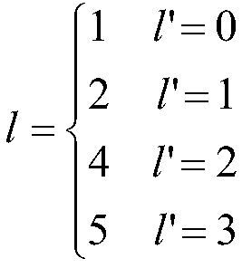
단계 1402: 이하의 수학식:Step 1402: the following equation:
![]()
![]()
에 따라 구성된 복조 기준 신호들에 자원 매핑을 수행하는 단계And performing resource mapping on the demodulation reference signals constructed according to Equation
를 포함한다..
여기에서,From here,

![]()
![]()
![]()
![]()
![]()
![]()

![]()
![]()


위의 수학식의 파라미터들의 의미는 3GPP TS36.211의 Section 6.10.3의 그것들과 동일하고, 여기서 더 이상 설명되지 않을 것이다. 예를 들어,![]()
![]()
![]()
![]()
![]()
![]()
![]()
![]()
![]()
![]()
![]()
![]()
![]()
![]()
![]()
![]()
![]()
![]()
![]()
![]()
![]()
![]()
![]()
![]()
![]()
![]()
![]()
![]()
이하의 수학식에서, ![]()
![]()
도 9a에 대응하여,9A,
주파수 영역 일련번호들이 상부로부터 하부로 오름차순으로 있는 경우,If the frequency domain serial numbers are in ascending order from top to bottom,
![]()
![]()
주파수 영역 일련번호들이 상부로부터 하부로 내림차순으로 있는 경우,If the frequency domain serial numbers are in descending order from top to bottom,
![]()
![]()
도 9b에 대응하여, ![]()
![]()
도 9c에 대응하여, 9C,
주파수 영역 일련번호들이 상부로부터 하부로 오름차순으로 있는 경우,If the frequency domain serial numbers are in ascending order from top to bottom,
![]()
![]()
주파수 영역 일련번호들이 상부로부터 하부로 내림차순으로 있는 경우,If the frequency domain serial numbers are in descending order from top to bottom,
![]()
![]()
도 9d에 대응하여,9D,
주파수 영역 일련번호들이 상부로부터 하부로 오름차순으로 있는 경우,If the frequency domain serial numbers are in ascending order from top to bottom,

주파수 영역 일련번호들이 상부로부터 하부로 내림차순으로 있는 경우,If the frequency domain serial numbers are in descending order from top to bottom,

도 9e에 대응하여,9E,
주파수 영역 일련번호들이 상부로부터 하부로 오름차순으로 있는 경우,If the frequency domain serial numbers are in ascending order from top to bottom,

주파수 영역 일련번호들이 상부로부터 하부로 내림차순으로 있는 경우,If the frequency domain serial numbers are in descending order from top to bottom,

도 10a에 대응하여,Corresponding to Fig. 10A,
주파수 영역 일련번호들이 상부로부터 하부로 오름차순으로 있는 경우,If the frequency domain serial numbers are in ascending order from top to bottom,

주파수 영역 일련번호들이 상부로부터 하부로 내림차순으로 있는 경우,If the frequency domain serial numbers are in descending order from top to bottom,

도 10b에 대응하여,Corresponding to Fig. 10B,
주파수 영역 일련번호들이 상부로부터 하부로 오름차순으로 있는 경우,If the frequency domain serial numbers are in ascending order from top to bottom,

주파수 영역 일련번호들이 상부로부터 하부로 내림차순으로 있는 경우,If the frequency domain serial numbers are in descending order from top to bottom,

도 10c에 대응하여,Corresponding to Fig. 10C,
주파수 영역 일련번호들이 상부로부터 하부로 오름차순으로 있는 경우,If the frequency domain serial numbers are in ascending order from top to bottom,

주파수 영역 일련번호들이 상부로부터 하부로 내림차순으로 있는 경우,If the frequency domain serial numbers are in descending order from top to bottom,
![]()
![]()
도 10d에 대응하여,Corresponding to Fig. 10D,
주파수 영역 일련번호들이 상부로부터 하부로 오름차순으로 있는 경우,If the frequency domain serial numbers are in ascending order from top to bottom,
![]()
![]()
주파수 영역 일련번호들이 상부로부터 하부로 내림차순으로 있는 경우,If the frequency domain serial numbers are in descending order from top to bottom,

도 11a에 대응하여,
도 11b에 대응하여, 
도 11c에 대응하여,
도 11d에 대응하여,
이 실시예에서,![]()
![]()

이 실시예의 매핑하기 위한 방법이 보다 명백하고 쉽게 이해되기 위하여, 2개의 PRB 쌍 내의 24개의 위치에서 파일럿 시퀀스들 및 ![]()
![]()
파일럿 시퀀스들:Pilot sequences:

이 예시에서, a11 및 a12가 도 8에 표시된 문자 A와 대응되고, a31 및 a41이 도 8에 표시된 문자 B에 대응되고, a12 및 a22이 도 8에 표시된 문자 C에 대응되고, a32 및 a42이 도 8에 표시된 문자 D에 대응되고, a13 및 a23이 도 8에 표시된 문자 E에 대응되고, a33 및 a43이 도 8에 표시된 문자 F에 대응되고, 그와 같이 계속된다. 추가로, 표의 앞의 세 줄은 하나의 PRB 쌍에 대응되고, 표의 뒤의 세 줄은 또 다른 PRB 쌍에 대응된다.In this example, a11 and a12 correspond to the letter A shown in Fig. 8, a31 and a41 correspond to the letter B shown in Fig. 8, a12 and a22 correspond to the letter C shown in Fig. 8, Corresponds to the letter D shown in Fig. 8, a13 and a23 correspond to the letter E shown in Fig. 8, a33 and a43 correspond to the letter F shown in Fig. 8, and so on. In addition, the three lines before the table correspond to one PRB pair, and the three lines after the table correspond to another PRB pair.
![]()
![]()

이 예시에서, ![]()
![]()
이 실시예의 방법에 따르면, 도 10a에 도시된 패턴들에 따라서 DMRS들이 구성된 후에, RB 자원 내의 16개 위치의 확산 코드(spreading codes) 및 파일럿 시퀀스들은 이하에 각각 표시된다:According to the method of this embodiment, after the DMRSs are configured according to the patterns shown in FIG. 10A, the spreading codes and pilot sequences of the 16 positions in the RB resources are indicated below respectively:
파일럿 시퀀스들:Pilot sequences:

![]()
![]()

위에 표시된 바와 같이, 실시예 3의 방법에 따라 DMRS들을 구성하고, 파일럿 시퀀스들을 생성하기 위한 기존 방법을 사용하여 DMRS들을 생성하고 이 실시예의 매핑하기 위한 방법에 따라 DMRS들을 매핑한 후에, 비워진 위치의 RE들은 데이터 전송을 위해 사용될 수 있다.As indicated above, after configuring the DMRSs according to the method of
실시예 3의 방법을 사용하여 DMRS들을 구성하고 이 실시예의 방법을 사용하여 DMRS들을 매핑함으로써, LTE의 최신 출시들(출시 12 또는 그 이상)에서 데이터 처리량이 향상될 수 있다.By configuring the DMRSs using the method of
본 발명의 실시예는 이하 실시예 5에 설명된 것과 같은 eNB를 더 제공한다. 문제를 해결하기 위한 eNB의 원리가 실시예 1의 방법의 그것과 유사하므로, 실시예 1에서의 방법의 구현이 eNB의 구현을 위해 참조될 수 있고, 반복되는 부분들은 더 이상 설명되지 않을 것이다.Embodiments of the present invention further provide an eNB as described in Example 5 below. Since the principle of the eNB for solving the problem is similar to that of the method of the first embodiment, an implementation of the method in the first embodiment can be referred to for the implementation of the eNB, and the repeated parts will not be described any further.
실시예 5Example 5
본 발명의 실시예는 DMRS들을 구성하기 위한 eNB를 더 제공한다. 도 15는 eNB의 구조의 개략도이다. 도 15를 참조하여, eNB는,Embodiments of the present invention further provide an eNB for configuring DMRSs. 15 is a schematic view of the structure of the eNB. Referring to Fig. 15,
하나의 PRB 쌍 내의 4개의 OFDM 기호들에 의해 운반되는 DMRS들을 구성하도록 구성된 구성 유닛(151) - 4개의 OFDM 기호들은 2개의 그룹으로 나뉘고, 각각의 그룹은 두 이웃하는 OFDM 기호들로 구성되고, OFDM 기호들의 2개의 그룹 사이의 거리는 5개의 OFDM 기호보다 큼 - 을 포함한다.A configuration unit (151) configured to configure DMRSs carried by four OFDM symbols in one PRB pair, the four OFDM symbols being divided into two groups, each group consisting of two neighboring OFDM symbols, The distance between two groups of OFDM symbols is greater than five OFDM symbols.
일 실시예에서, OFDM 기호들의 2개의 그룹의 위치는 PRB 쌍을 구성하는 2개의 슬롯의 경계에 대해 대칭적이다.In one embodiment, the positions of the two groups of OFDM symbols are symmetric about the boundaries of the two slots making up the PRB pair.
일 구현에서, OFDM 기호들의 제1 그룹은 제1 슬롯의 앞의 2개의 OFDM 기호들이고, OFDM 기호들의 제2 그룹은 제2 슬롯의 뒤의 2개의 OFDM 기호들이다.In one implementation, the first group of OFDM symbols are the two OFDM symbols preceding the first slot, and the second group of OFDM symbols are the two OFDM symbols after the second slot.
다른 구현에서, OFDM 기호들의 제1 그룹은 제1 슬롯의 제2 및 제3 OFDM 기호들이고, OFDM 기호들의 제2 그룹은 제2 슬롯의 제5 및 제6 OFDM 기호들이다.In another implementation, the first group of OFDM symbols are the second and third OFDM symbols of the first slot, and the second group of OFDM symbols are the fifth and sixth OFDM symbols of the second slot.
다른 실시예에서, OFDM 기호들의 2개의 그룹의 위치들은 PRB 쌍을 구성하는 2개의 슬롯들의 경계에 대해 비대칭적이다.In another embodiment, the positions of the two groups of OFDM symbols are asymmetric about the boundaries of the two slots making up the PRB pair.
일 구현에서, OFDM 기호들의 제1 그룹은 제1 슬롯의 제2 및 제3 OFDM 기호들이고, OFDM 기호들의 제2 그룹은 제2 슬롯의 뒤의 2개의 OFDM 기호들이다.In one implementation, the first group of OFDM symbols are the second and third OFDM symbols of the first slot, and the second group of OFDM symbols are the two OFDM symbols after the second slot.
다른 구현에서, OFDM 기호들의 제1 그룹은 제1 슬롯의 제3 및 제4 OFDM 기호들이고, OFDM 기호들의 제2 그룹은 제2 슬롯의 뒤의 2개의 OFDM 기호들이다.In another implementation, the first group of OFDM symbols are the third and fourth OFDM symbols of the first slot, and the second group of OFDM symbols are the two OFDM symbols after the second slot.
추가 구현에서, OFDM 기호들의 제1 그룹은 제1 슬롯의 제4 및 제5 OFDM 기호들이고, OFDM 기호들의 제2 그룹은 제2 슬롯의 뒤의 2개의 OFDM 기호들이다.In a further implementation, the first group of OFDM symbols are the fourth and fifth OFDM symbols of the first slot, and the second group of OFDM symbols are the two OFDM symbols after the second slot.
이 실시예에서, 하나 이상의 포트들에 대응되는 DMRS들이 코드 분할 체계를 사용함으로써 주파수 영역 내의 제1, 제6 및 제11 자원 요소들(RE들)을 점유하거나, 하나 이상의 포트에 대응되는 DMRS들이 코드 분할 체계를 사용함으로써 주파수 영역 내의 제2, 제7 및 제12 RE들을 점유한다. In this embodiment, the DMRSs corresponding to one or more ports occupy the first, sixth and eleventh resource elements (REs) in the frequency domain by using a code division scheme, or the DMRSs corresponding to one or more ports Occupies the second, seventh, and twelfth REs in the frequency domain by using a code division scheme.
이 실시예의 eNB를 사용하여 DMRS들을 구성함으로써, LTE의 최신 출시들(출시 12 또는 그 이상)에서의 DMRS들에 기반한 채널 추정의 성능은 향상될 수 있다.By configuring DMRSs using the eNB of this embodiment, the performance of channel estimation based on DMRSs in the latest releases of LTE (
본 발명의 실시예는 이하의 실시예 6에서 설명된 것과 같은 eNB를 더 제공한다. 문제를 해결하기 위한 eNB의 원리가 실시예 2의 방법의 그것과 유사하므로, 실시예 2에서의 방법의 구현이 eNB의 구현에 대해 참조될 수도 있고, 반복되는 부분들은 더 이상 설명되지 않을 것이다.The embodiment of the present invention further provides an eNB as described in the following
실시예 6Example 6
본 발명의 실시예는 DMRS들을 매핑하기 위한 eNB를 더 제공한다. 도 16은 eNB의 구조의 개략도이다. 도 16을 참조하면, eNB는The embodiment of the present invention further provides an eNB for mapping DMRSs. 16 is a schematic view of the structure of the eNB. Referring to Figure 16, the eNB
실시예 1에서 설명된 복조 기준 신호를 구성하기 위한 방법에 따라 LTE 시스템을 위한 PRB 쌍의 복조 기준 신호들을 구성하도록 구성된 구성 유닛(161); 및A configuration unit (161) configured to configure demodulation reference signals of the PRB pair for the LTE system according to a method for constructing the demodulation reference signal described in the first embodiment; And
이하의 수학식:The following formula:
![]()
![]()
에 따라, 구성된 복조 기준 신호들에 자원 매핑을 수행하도록 구성된 매핑 유닛(162)A
을 포함한다..
여기에서,From here,

이고;ego;
![]()
![]()
![]()
![]()


이고;ego;
위의 변수들의 의미는 3GPP TS36.211의 Section 6.10.3의 그것들과 동일하고, 여기서 더 이상 설명되지 않을 것이다. The meanings of the above variables are the same as those in Section 6.10.3 of 3GPP TS36.211, and will not be further described here.
이 실시예의 eNB를 사용하여 DMRS들을 매핑함으로써, LTE의 최신 출시들(출시 12 또는 그 이상)에서의 DMRS들에 기반한 채널 추정의 성능이 향상될 수 있다.By mapping the DMRSs using the eNB of this embodiment, the performance of channel estimation based on DMRSs in the latest releases of LTE (
본 발명의 실시예는 이하의 실시예 7에서 설명된 것과 같은 eNB를 더 제공한다. 문제를 해결하기 위한 eNB의 원리가 실시예 3의 방법의 그것과 유사하므로, 실시예 3에서의 방법의 구현이 eNB의 구현을 위해 참조될 수도 있고, 반복되는 부분들은 더 이상 설명되지 않을 것이다.The embodiment of the present invention further provides an eNB as described in the following seventh embodiment. Since the principle of the eNB for solving the problem is similar to that of the method of the
실시예 7Example 7
본 발명의 실시예는 DMRS들을 구성하기 위한 eNB를 더 제공한다. 도 17은 eNB의 구조의 개략도이다. 도 17을 참조하여, eNB는Embodiments of the present invention further provide an eNB for configuring DMRSs. 17 is a schematic view of the structure of the eNB. Referring to Fig. 17, the eNB
각각의 PRB 쌍 내에 DMRS들의 6개보다 적은 그룹을 구성하도록 구성된 구성 유닛(171) - DMRS들의 그룹의 각각은 DMRS들을 운반하는 2개의 RE로 구성되고, DMRS들을 운반하는 2개의 RE들은 동일한 서브캐리어 내에 위치하고 두 이웃하는 OFDM 기호들을 점유함 - 을 포함하고,A configuration unit (171) configured to configure less than six groups of DMRSs in each PRB pair - each group of DMRSs comprises two REs carrying DMRSs, and two REs carrying DMRSs comprise the same subcarrier And occupies two neighboring OFDM symbols,
여기에서, 하나 이상의 포트들에 대응되는 DMRS들이 코드 분할 체계를 사용함으로써 주파수 영역 내의 제1, 제6 및 제11 자원 요소들(RE들)을 점유하거나, 하나 이상의 포트에 대응되는 DMRS들이 코드 분할 체계를 사용함으로써 주파수 영역 내의 제2, 제7 및 제12 RE들을 점유한다. Here, it is assumed that the DMRSs corresponding to one or more ports occupy the first, sixth and eleventh resource elements (REs) in the frequency domain by using a code division scheme, or the DMRSs corresponding to one or more ports are code division Seventh, and twelfth REs in the frequency domain by using the system.
일 실시예에서, 각각의 PRB 쌍에 DMRS들의 4개의 그룹이 구성되어 있는 경우, 구성 유닛(171)은 시간 영역 내의 DMRS들의 4개의 그룹의 위치와 밀도를 일정하게 유지하고, 주파수 영역 내의 위치들의 3개의 그룹 중 임의의 2개의 그룹에 DMRS들의 4개의 그룹을 구성하도록 구성된다.In one embodiment, when four groups of DMRSs are configured in each PRB pair, the
다른 실시예에서, 각각의 PRB 쌍에 DMRS들의 4개의 그룹이 구성되어 있는 경우, 구성 유닛(171)은 시간 영역 내의 DMRS들의 4개의 그룹의 위치와 밀도를 일정하게 유지하고, 주파수 영역 내의 위치들의 3개의 그룹 중 중간 그룹에 DMRS들의 4개의 그룹 중 DMRS들의 2개의 그룹을 구성하고, DMRS들의 4개의 그룹 중 다른 2개의 그룹을 주파수 영역 내의 위치들의 3개의 그룹 중 제1 및 제3 그룹에 구성하도록 구성되고, 위치들의 제1 그룹에 구성된 DMRS들과 위치들의 제3 그룹에 구성된 DMRS들은 PRB 쌍의 상이한 슬롯들에 위치된다.In another embodiment, when four groups of DMRSs are configured in each PRB pair, the
추가 실시예에서, 각각의 PRB 쌍에 DMRS들의 3개의 그룹이 구성되어 있는 경우, 구성 유닛(171)은 시간 영역 내의 DMRS들의 3개의 그룹의 위치와 밀도를 일정하게 유지하고, 주파수 영역 내의 위치들의 3개의 그룹에 각각 DMRS들의 3개의 그룹을 구성하도록 구성되고, 위치들의 제1 그룹에 구성된 DMRS들과 위치들의 제3 그룹에 구성된 DMRS들은 PRB 쌍의 동일한 슬롯에 위치되고, 위치들의 제2 그룹에서 구성된 DMRS들과 위치들의 제1 및 제3 그룹에서 구성된 DMRS들은 PRB 쌍의 상이한 슬롯들에 위치된다.In a further embodiment, when three groups of DMRSs are configured in each PRB pair, the
이 실시예에서, 4개의 OFDM 기호들이 하나의 PRB 쌍에서 DMRS들을 운반하기 위해 사용되고, 4개의 OFDM 기호들은 2개의 그룹으로 나뉘고, 각각의 그룹은 2개의 이웃하는 OFDM 기호들로 구성된다.In this embodiment, four OFDM symbols are used to carry DMRSs in one PRB pair, the four OFDM symbols are divided into two groups, and each group consists of two neighboring OFDM symbols.
다른 실시예에서, DMRS들은 도 12a 내지 12d에 도시된 낮춰진 주파수 영역 밀도를 가지는 파일럿 패턴으로서, 또는 도 13a 내지 13b에 도시된 낮춰진 시간 영역 밀도를 가지는 파일럿 패턴으로서 구성될 수 있다.In other embodiments, the DMRSs may be configured as a pilot pattern with a reduced frequency domain density shown in Figs. 12A-12D, or as a pilot pattern with a reduced time domain density shown in Figs. 13A-13B.
이 실시예의 eNB를 사용하여 DMRS를 구성함으로써, LTE의 최신 출시들(출시 12 또는 그 이상)에서의 DMRS들에 기반한 채널 추정의 성능은 향상될 수 있다.By configuring the DMRS using the eNB of this embodiment, the performance of channel estimation based on DMRSs in the latest releases of LTE (
실시예 8Example 8
본 발명의 실시예는 DMRS들을 매핑하기 위한 eNB를 더 제공한다. 도 18은 eNB의 구조의 개략도이다. 도 18을 참조하여, eNB는,The embodiment of the present invention further provides an eNB for mapping DMRSs. 18 is a schematic view of the structure of the eNB. Referring to Fig. 18,
실시예 3에서 설명된 것과 같은 복조 기준 신호를 구성하기 위한 방법에 따라 LTE 시스템을 위한 PRB 쌍의 복조 기준 신호들을 구성하도록 구성된 구성 유닛(181); 및A configuration unit (181) configured to configure demodulation reference signals of a PRB pair for an LTE system according to a method for constructing a demodulation reference signal as described in the third embodiment; And
이하의 수학식:The following formula:
![]()
![]()
에 따라, 구성된 복조 기준 신호들에 자원 매핑을 수행하도록 구성된 매핑 유닛(182)A
을 포함한다..
여기에서,From here,

이고;ego;
![]()
![]()
![]()
![]()
기존 표준에 기반하여 


m의 값은 이하와 같다:The value of m is:
도 9a에 대응하여,9A,
주파수 영역 일련번호들이 상부로부터 하부로 오름차순으로 있는 경우,If the frequency domain serial numbers are in ascending order from top to bottom,
![]()
![]()
주파수 영역 일련번호들이 상부로부터 상부의 하강 순서로 있는 경우,If the frequency domain serial numbers are in descending order from top to top,
![]()
![]()
도 9b에 대응하여, ![]()
![]()
도 9c에 대응하여, 9C,
주파수 영역 일련번호들이 상부로부터 하부로 오름차순으로 있는 경우,If the frequency domain serial numbers are in ascending order from top to bottom,
![]()
![]()
주파수 영역 일련번호들이 상부로부터 하부로 내림차순으로 있는 경우,If the frequency domain serial numbers are in descending order from top to bottom,
![]()
![]()
도 9d에 대응하여,9D,
주파수 영역 일련번호들이 상부로부터 하부로 오름차순으로 있는 경우,If the frequency domain serial numbers are in ascending order from top to bottom,

주파수 영역 일련번호들이 상부로부터 하부로 내림차순으로 있는 경우,If the frequency domain serial numbers are in descending order from top to bottom,

도 9e에 대응하여,9E,
주파수 영역 일련번호들이 상부로부터 하부로 오름차순으로 있는 경우,If the frequency domain serial numbers are in ascending order from top to bottom,

주파수 영역 일련번호들이 상부로부터 하부로 내림차순으로 있는 경우,If the frequency domain serial numbers are in descending order from top to bottom,

도 10a에 대응하여,Corresponding to Fig. 10A,
주파수 영역 일련번호들이 상부로부터 하부로 오름차순으로 있는 경우,If the frequency domain serial numbers are in ascending order from top to bottom,

주파수 영역 일련번호들이 상부로부터 하부로 내림차순으로 있는 경우,If the frequency domain serial numbers are in descending order from top to bottom,

도 10b에 대응하여,Corresponding to Fig. 10B,
주파수 영역 일련번호들이 상부로부터 하부로 오름차순으로 있는 경우,If the frequency domain serial numbers are in ascending order from top to bottom,

주파수 영역 일련번호들이 상부로부터 하부로 내림차순으로 있는 경우,If the frequency domain serial numbers are in descending order from top to bottom,

도 10c에 대응하여,Corresponding to Fig. 10C,
주파수 영역 일련번호들이 상부로부터 하부로 오름차순으로 있는 경우,If the frequency domain serial numbers are in ascending order from top to bottom,

주파수 영역 일련번호들이 상부로부터 하부로 내림차순으로 있는 경우,If the frequency domain serial numbers are in descending order from top to bottom,
![]()
![]()
도 10d에 대응하여,Corresponding to Fig. 10D,
주파수 영역 일련번호들이 상부로부터 하부로 오름차순으로 있는 경우,If the frequency domain serial numbers are in ascending order from top to bottom,
![]()
![]()
주파수 영역 일련번호들이 상부로부터 하부로 내림차순으로 있는 경우,If the frequency domain serial numbers are in descending order from top to bottom,

도 11a에 대응하여,
도 11b에 대응하여, 
도 11c에 대응하여,
도 11d에 대응하여,
이 실시예의 eNB를 사용하여 DMRS들을 매핑함으로써, LTE의 최신 출시들(출시 12 또는 그 이상)에서의 데이터 처리량이 향상될 수 있다.By mapping the DMRSs using the eNB of this embodiment, the data throughput in the latest releases of LTE (
실시예 9Example 9
본 발명의 실시예는 채널 추정을 수행하기 위한 방법을 더 제공한다. 도 19는 방법의 흐름도이다. 도 19를 참조하여, 방법은 이하의 단계들을 포함한다,Embodiments of the present invention further provide a method for performing channel estimation. 19 is a flow chart of the method. Referring to Figure 19, the method includes the following steps:
단계 1901: 실시예 1 또는 실시예 3에 설명된 것과 같은 방법에 따라 구성된 DMRS들의 위치에 따라 UE에 의해 수신된 신호로부터 DMRS들을 추출하는 단계;Step 1901: extracting the DMRSs from the signal received by the UE according to the location of the constructed DMRSs according to the method as described in the first or third embodiment;
일 실시예에서, DMRS들은 실시예 1의 방법에 따라 eNB에 의해 구성되고 실시예 2의 방법에 따라 대응되는 물리 자원 블록 쌍들의 위치들에 eNB에 의해 매핑된 후에 전송되며; 다른 실시예에서, DMRS들은 실시예 3의 방법에 따라 eNB에 의해 구성되고 실시예 4의 방법 또는 기존 표준의 방법에 따라 대응되는 물리 자원 블록 쌍들의 위치들에 eNB에 의해 매핑된 후에 전송되므로; UE는 대응되는 위치에서 그 자신의 DMRS를 추출할 수 있다.In one embodiment, the DMRSs are configured by an eNB according to the method of
단계 1902: eNB에 의해 구성된 DMRS들에 따라 UE에 의해 DMRS 시퀀스를 생성하는 단계;Step 1902: generating a DMRS sequence by the UE according to the DMRSs configured by the eNB;
UE는 기존 표준의 방법에 따라 DMRS 시퀀스를 생성할 수 있고, 여기서 더 이상 설명되지 않을 것이다;The UE may generate the DMRS sequence according to the methods of the existing standard and will not be further described here;
단계 1903: 생성된 DMRS 시퀀스와 추출된 DMRS들에 따라 전송에서 수신된 신호들에 의해 통과되는 채널 상에 UE에 의해 채널 추정을 수행하는 단계;Step 1903: Perform channel estimation by the UE on the channel that is passed by the signals received in the transmission according to the generated DMRS sequence and the extracted DMRSs;
UE는 로컬에서(locally) 생성된 DMRS 시퀀스들 및 수신된 DMRS들을 사용하여 전송에서의 수신된 신호들에 의해 통과되는 채널 상에 채널 추정을 수행할 수 있고; 이 실시예에서 채널 추정을 수행하는 구체적 방법은 제한되지 않고, LS 알고리즘, MMSE 알고리즘, DFT 알고리즘, 또는 다양한 보간 알고리즘(interpolation algorithms)이 사용될 수 있다.The UE is able to perform channel estimation on a channel that is passed by the received signals in the transmission using locally generated DMRS sequences and received DMRSs; The specific method of performing channel estimation in this embodiment is not limited, and an LS algorithm, an MMSE algorithm, a DFT algorithm, or various interpolation algorithms may be used.
이 실시예의 방법으로, 채널 추정의 성능이 향상될 수 있다.With the method of this embodiment, the performance of channel estimation can be improved.
본 발명의 실시예는 이하의 실시예 10에서 설명된 것과 같은 UE를 더 제공한다. 문제를 해결하기 위한 UE의 원리가 실시예 9의 방법의 그것과 유사하므로, 실시예 9에서의 방법의 구현이 UE의 구현을 위해 참조될 수도 있고, 반복되는 부분들은 더 이상 설명되지 않을 것이다.The embodiment of the present invention further provides a UE as described in the tenth embodiment below. Since the principle of the UE for solving the problem is similar to that of the method of the
실시예 10Example 10
본 발명의 실시예는 UE를 더 제공한다. 도 20은 UE의 구조의 개략도이다. 도 20을 참조하여, UE는The embodiment of the present invention further provides a UE. 20 is a schematic diagram of the structure of a UE. Referring to FIG. 20,
실시예 1 또는 실시예 3에 따라 구성된 DMRS들의 위치에 따라 수신된 신호로부터 DMRS들을 추출하도록 구성된 추출 유닛(201);An extraction unit (201) configured to extract DMRSs from the received signal according to the positions of the DMRSs constructed according to the first or third embodiment;
eNB에 의해 구성된 DMRS들에 따라 DMRS 시퀀스를 생성하도록 구성된 생성 유닛(202); 및a generating unit (202) configured to generate a DMRS sequence in accordance with the DMRSs configured by the eNB; And
생성된 DMRS 시퀀스 및 추출된 DMRS들에 따라 전송에서 수신된 신호들에 의해 통과되는 채널 상에 채널 추정을 수행하도록 구성된 채널 추정 유닛(203)A channel estimation unit (203) configured to perform channel estimation on the channel that is passed by the signals received in the transmission in accordance with the generated DMRS sequence and the extracted DMRSs,
을 포함한다..
이 실시예의 UE로, 채널 추정의 성능이 향상될 수 있다.With the UE of this embodiment, the performance of channel estimation can be improved.
본 발명의 실시예는 실시예 5 내지 8에서 설명된 것과 같은 eNB 및 실시예 10에서 설명된 것과 같은 UE를 포함하는 통신 시스템을 더 제공한다.Embodiments of the present invention further provide an eNB as described in the
본 발명의 실시예는 컴퓨터-판독가능한 프로그램을 더 제공하고, 프로그램이 eNB에서 실행될 때, 프로그램은 컴퓨터가 실시예 2 및 실시예 4에서 설명한 것과 같은 복조 기준 신호들을 매핑하기 위한 방법 또는 실시예 1 및 실시예 3에서 설명한 것과 같은 복조 기준 신호들을 구성하기 위한 방법을 eNB에서 실행하는 것을 가능하게 한다.The embodiment of the present invention further provides a computer-readable program, and when the program is executed in the eNB, the program causes the computer to perform a method for mapping the demodulation reference signals as described in the
본 발명의 실시예는 컴퓨터-판독가능한 프로그램이 저장된 저장 매체를 더 제공하고, 컴퓨터-판독가능한 프로그램은 컴퓨터가 실시예 2 및 실시예 4에서 설명한 것과 같은 복조 기준 신호들을 매핑하기 위한 방법 또는 실시예 1 및 실시예 3에서 설명한 것과 같은 복조 기준 신호들을 구성하기 위한 방법을 eNB에서 실행하는 것을 가능하게 한다.An embodiment of the present invention further provides a storage medium having a computer-readable program stored thereon, wherein the computer-readable program causes the computer to perform a method or embodiment for mapping demodulation reference signals as described in the second and
본 발명의 실시예는 컴퓨터-판독가능한 프로그램을 더 제공하고, 프로그램이 단말 장비에서 실행될 때, 프로그램은 컴퓨터가 실시예 9에서 설명한 대로 채널 추정을 수행하기 위한 방법을 단말 장비에서 실행하는 것을 가능하게 한다.Embodiments of the present invention further provide a computer-readable program that, when the program is executed on a terminal equipment, enables the computer to execute on the terminal equipment a method for performing channel estimation as described in
본 발명의 실시예는 컴퓨터-판독가능한 프로그램이 저장된 저장 매체를 더 제공하고, 컴퓨터-판독가능한 프로그램은 컴퓨터가 실시예 9에서 설명한 대로 채널 추정을 수행하기 위한 방법을 단말 장비에서 실행하는 것을 가능하게 한다.An embodiment of the present invention further provides a storage medium on which a computer-readable program is stored, wherein the computer-readable program enables the computer to execute on the terminal equipment a method for performing channel estimation as described in the ninth embodiment do.
본 발명의 위의 장치 및 방법은 하드웨어, 또는 소프트웨어와 조합된 하드웨어로 구현될 수 있다. 본 발명은 논리 장치에 의해 실행될 때, 논리 장치가 위에서 설명된 것과 같은 장치 또는 구성요소들을 실행하거나 위에서 설명된 것과 같은 방법 또는 단계들을 실행하는 것이 가능해지는 컴퓨터-판독가능한 프로그램에 관한 것이다. 본 발명은 또한 위의 프로그램을 저장하기 위한 하드 디스크, 플로피 디스크, CD, DVD, 및 플래시 메모리 등과 같은 저장 매체에 관한 것이다.The above apparatus and method of the present invention may be implemented in hardware, or hardware combined with software. The present invention relates to a computer-readable program that, when executed by a logic device, enables a logic device to execute a device or component as described above or to execute a method or steps as described above. The present invention also relates to a storage medium such as a hard disk, a floppy disk, a CD, a DVD, and a flash memory for storing the above program.
본 발명은 구체적인 실시예들을 참조하여 위에 설명되어있다. 그러나, 기술분야에 숙련된 자들에 의해 이러한 설명은 예시적일 뿐이고, 본 발명의 보호범위를 제한하는 것을 의도하지 않는다는 것이 이해되어야 한다. 다양한 변형과 수정들이 기술분야에 숙련된 자들에 의해 본 발명의 원리에 따라 만들어질 수 있고, 이러한 변형과 수정들은 본 발명의 범위 내이다. The invention has been described above with reference to specific embodiments. It should be understood, however, that such description is exemplary only by those skilled in the art, and is not intended to limit the scope of protection of the present invention. Various modifications and alterations may be made by those skilled in the art in accordance with the principles of the present invention, and such variations and modifications are within the scope of the present invention.
Claims (41)
하나의 물리 자원 블록(physical resource block)(PRB) 쌍 내의 4개의 직교 주파수 분할 다중(orthogonal frequency division multiplexing)(OFDM) 기호들에 의해 운반되는 복조 기준 신호들(DMRS들)을 구성하는 단계를 포함하고,
상기 4개의 OFDM 기호들은 2개의 그룹으로 나뉘고, 각각의 그룹은 2개의 이웃하는 OFDM 기호로 구성되고, 상기 OFDM 기호들의 2개의 그룹 사이의 거리는 5개의 OFDM 기호보다 더 큰, 방법.CLAIMS What is claimed is: 1. A method for configuring demodulation reference signals,
Comprises constructing demodulation reference signals (DMRSs) carried by four orthogonal frequency division multiplexing (OFDM) symbols in one physical resource block (PRB) pair and,
Wherein the four OFDM symbols are divided into two groups, each group consisting of two neighboring OFDM symbols, the distance between the two groups of OFDM symbols being greater than five OFDM symbols.
상기 OFDM 기호들의 2개의 그룹의 위치들은 상기 하나의 PRB 쌍을 구성하는 2개의 슬롯들의 경계에 대해 대칭적인, 방법.The method according to claim 1,
Wherein positions of two groups of OFDM symbols are symmetric with respect to a boundary of two slots constituting the one PRB pair.
OFDM 기호들의 제1 그룹은 제1 슬롯의 앞의 2개의 OFDM 기호들이고, OFDM 기호들의 제2 그룹은 제2 슬롯의 뒤의 2개의 OFDM 기호들인, 방법.3. The method of claim 2,
Wherein the first group of OFDM symbols is the two OFDM symbols preceding the first slot and the second group of OFDM symbols is the two OFDM symbols after the second slot.
OFDM 기호들의 제1 그룹은 제1 슬롯의 제2 및 제3 OFDM 기호들이고, OFDM 기호들의 제2 그룹은 제2 슬롯의 제5 및 제6 OFDM 기호들인, 방법.3. The method of claim 2,
Wherein the first group of OFDM symbols is the second and third OFDM symbols of the first slot and the second group of OFDM symbols is the fifth and sixth OFDM symbols of the second slot.
상기 OFDM 기호들의 2개의 그룹의 위치들은 상기 하나의 PRB 쌍을 구성하는 2개의 슬롯들의 경계에 대해 비대칭적인, 방법.The method according to claim 1,
Wherein positions of two groups of OFDM symbols are asymmetric with respect to a boundary of two slots constituting the one PRB pair.
OFDM 기호들의 제1 그룹은 제1 슬롯의 제2 및 제3 OFDM 기호들이고, OFDM 기호들의 제2 그룹은 제2 슬롯의 뒤의 2개의 OFDM 기호들인, 방법.6. The method of claim 5,
Wherein the first group of OFDM symbols is the second and third OFDM symbols of the first slot and the second group of OFDM symbols is the two OFDM symbols after the second slot.
OFDM 기호들의 제1 그룹은 제1 슬롯의 제3 및 제4 OFDM 기호들이고, OFDM 기호들의 제2 그룹은 제2 슬롯의 뒤의 2개의 OFDM 기호들인, 방법.6. The method of claim 5,
Wherein the first group of OFDM symbols is the third and fourth OFDM symbols of the first slot and the second group of OFDM symbols is the two OFDM symbols after the second slot.
OFDM 기호들의 제1 그룹은 제1 슬롯의 제4 및 제5 OFDM 기호들이고, OFDM 기호들의 제2 그룹은 제2 슬롯의 뒤의 2개의 OFDM 기호들인, 방법.6. The method of claim 5,
Wherein the first group of OFDM symbols is the fourth and fifth OFDM symbols of the first slot and the second group of OFDM symbols is the two OFDM symbols after the second slot.
하나 이상의 포트에 대응되는 상기 DMRS들이 코드 분할 체계(code division scheme)를 사용함으로써 주파수 영역 내의 제1, 제6 및 제11 자원 요소들(RE들)을 점유하거나, 하나 이상의 포트에 대응되는 상기 DMRS들이 코드 분할 체계를 사용함으로써 주파수 영역 내의 제2, 제7 및 제12 RE들을 점유하는, 방법.9. The method according to any one of claims 2 to 8,
The DMRSs corresponding to one or more ports occupy the first, sixth and eleventh resource elements (REs) in the frequency domain by using a code division scheme, or the DMRSs corresponding to one or more ports Seventh, and twelfth REs in the frequency domain by using a code division scheme.
제1항 내지 제9항 중 어느 한 항의 복조 기준 신호들을 구성하기 위한 방법에 따라 LTE 시스템을 위한 PRB 쌍의 복조 기준 신호들을 구성하는 단계; 및
이하의 수학식:
에 따라 구성된 복조 기준 신호들에 자원 매핑을 수행하는 단계를 포함하고,
여기에서,

이고;


인, 방법.A method for mapping a demodulation reference signal,
Constructing a PRB pair of demodulation reference signals for an LTE system according to a method for constructing demodulation reference signals of any one of claims 1 to 9; And
The following formula:
And performing resource mapping on the demodulation reference signals constructed according to Equation
From here,
ego;
In method.
각각의 PRB 쌍 내의 DMRS들의 6개보다 적은 그룹을 구성하는 단계를 포함하고,
DMRS들의 그룹의 각각은 상기 DMRS들을 운반하는 2개의 RE들로 구성되고, 상기 DMRS들을 운반하는 상기 2개의 RE들은 동일한 서브캐리어에 위치되고 2개의 이웃하는 OFDM 기호들을 점유하는, 방법.A method for constructing demodulation reference signals,
Constructing less than six groups of DMRSs in each PRB pair,
Wherein each of the groups of DMRSs comprises two REs carrying the DMRSs and the two REs carrying the DMRSs are located on the same subcarrier and occupy two neighboring OFDM symbols.
하나 이상의 포트에 대응되는 상기 DMRS들이 코드 분할 체계를 사용함으로써 주파수 영역 내의 제1, 제6 및/또는 제11 자원 요소들(RE들)을 점유하거나, 하나 이상의 포트에 대응되는 상기 DMRS들이 코드 분할 체계를 사용함으로써 주파수 영역 내의 제2, 제7 및/또는 제12 RE들을 점유하는, 방법.12. The method of claim 11,
The DMRSs corresponding to one or more ports occupy the first, sixth and / or eleventh resource elements (REs) in the frequency domain by using a code division scheme, or the DMRSs corresponding to one or more ports are code- Seventh, and / or twelfth REs in the frequency domain by using a system.
각각의 PRB 쌍 내에 DMRS들의 4개의 그룹이 구성되는 경우,
시간 영역 내의 상기 DMRS들의 4개의 그룹의 위치와 밀도를 일정하게 유지하고, 상기 DMRS들의 4개의 그룹을 주파수 영역 내의 위치들의 3개의 그룹 중 임의의 2개의 그룹에서 구성하는 단계
를 포함하는, 방법.13. The method of claim 12,
If four groups of DMRSs are configured in each PRB pair,
Maintaining the position and density of the four groups of DMRSs within the time domain constant and constructing the four groups of DMRSs in any two of the three groups of positions in the frequency domain
/ RTI >
각각의 PRB 쌍 내에 DMRS들의 4개의 그룹이 구성되는 경우,
시간 영역 내의 상기 DMRS들의 4개의 그룹의 위치와 밀도를 일정하게 유지하고, 상기 DMRS들의 4개의 그룹 중 2개의 그룹을 주파수 영역 내의 위치들의 3개의 그룹 중 중간 그룹에서 구성하고, 상기 DMRS들의 4개의 그룹 중 다른 2개의 그룹을 주파수 영역 내의 상기 위치들의 3개의 그룹 중 제1 및 제3 그룹에서 구성하는 단계를 포함하고,
상기 위치들의 제1 그룹에서 구성된 상기 DMRS들 및 상기 위치들의 제3 그룹에서 구성된 상기 DMRS들은 PRB 쌍의 상이한 슬롯들에 위치되는, 방법.13. The method of claim 12,
If four groups of DMRSs are configured in each PRB pair,
Maintaining the position and density of the four groups of DMRSs in the time domain constant and constructing two of the four groups of DMRSs in an intermediate group of three groups of positions in the frequency domain, Configuring the other two groups of groups in the first and third of the three groups of positions in the frequency domain,
Wherein the DMRSs configured in the first group of locations and the DMRSs configured in the third group of locations are located in different slots of the PRB pair.
각각의 PRB 쌍 내에 DMRS들의 3개의 그룹이 구성되는 경우,
시간 영역 내의 상기 DMRS들의 3개의 그룹의 위치와 밀도를 일정하게 유지하고, 상기 DMRS들의 3개의 그룹을 주파수 영역 내의 위치들의 3개의 그룹에서 각각 구성하는 단계를 포함하고,
위치들의 제1 그룹에 구성된 상기 DMRS들과 위치들의 제3 그룹에 구성된 상기 DMRS들은 PRB 쌍의 동일한 슬롯에 위치되고,
위치들의 제2 그룹에서 구성된 상기 DMRS들과 상기 위치들의 제1 및 제3 그룹에서 구성된 상기 DMRS들은 PRB 쌍의 상이한 슬롯들에 위치되는, 방법.13. The method of claim 12,
If three groups of DMRSs are configured in each PRB pair,
Maintaining the position and density of the three groups of DMRSs within the time domain constant and configuring the three groups of DMRSs in each of the three groups of locations in the frequency domain,
The DMRSs configured in the first group of positions and the DMRSs configured in the third group of positions are located in the same slot of the PRB pair,
Wherein the DMRSs configured in the second group of positions and the DMRSs configured in the first and third groups of positions are located in different slots of the PRB pair.
4개의 OFDM 기호들이 하나의 PRB 쌍 내의 DMRS들을 운반하는 데 사용되고;
상기 4개의 OFDM 기호들은 2개의 그룹으로 나뉘고, 각각의 그룹은 2개의 이웃하는 OFDM 기호로 구성되는, 방법.16. The method according to any one of claims 11 to 15,
Four OFDM symbols are used to carry the DMRSs in one PRB pair;
Wherein the four OFDM symbols are divided into two groups, each group consisting of two neighboring OFDM symbols.
제11항 내지 제16항 중 어느 한 항의 복조 기준 신호들을 구성하기 위한 방법에 따라 LTE 시스템을 위한 PRB 쌍의 복조 기준 신호들을 구성하는 단계; 및
이하의 수학식:
에 따라 구성된 복조 기준 신호들에 자원 매핑을 수행하는 단계를 포함하고, 여기에서,

이고;


인, 방법.A method for mapping a demodulation reference signal,
Constructing demodulation reference signals of a PRB pair for an LTE system according to a method for constructing demodulation reference signals of any of claims 11 to 16; And
The following formula:
And performing resource mapping on the demodulation reference signals constructed according to Equation
ego;
In method.
하나의 PRB 쌍 내의 4개의 OFDM 기호들에 의해 운반되는 DMRS들을 구성하도록 구성된 구성 유닛을 포함하고,
상기 4개의 OFDM 기호들은 2개의 그룹으로 나뉘고, 각각의 그룹은 2개의 이웃하는 OFDM 기호로 구성되고, 상기 OFDM 기호들의 2개의 그룹 사이의 거리는 5개의 OFDM 기호보다 더 큰, eNB.As an eNB that can be applied to construct DMRSs,
A configuration unit configured to configure the DMRSs carried by the four OFDM symbols in one PRB pair,
Wherein the four OFDM symbols are divided into two groups, each group consisting of two neighboring OFDM symbols, the distance between the two groups of OFDM symbols being greater than five OFDM symbols.
상기 OFDM 기호들의 2개의 그룹의 위치들은 상기 하나의 PRB 쌍을 구성하는 두 슬롯들의 경계에 대해 대칭적인, eNB.19. The method of claim 18,
The locations of the two groups of OFDM symbols are symmetric with respect to the boundaries of the two slots constituting the one PRB pair.
OFDM 기호들의 제1 그룹은 제1 슬롯의 앞의 2개의 OFDM 기호들이고, OFDM 기호들의 제2 그룹은 제2 슬롯의 뒤의 2개의 OFDM 기호들인, eNB.20. The method of claim 19,
The first group of OFDM symbols are the two OFDM symbols preceding the first slot and the second group of OFDM symbols are the two OFDM symbols after the second slot.
OFDM 기호들의 제1 그룹은 제1 슬롯의 제2 및 제3 OFDM 기호들이고, OFDM 기호들의 제2 그룹은 제2 슬롯의 제5 및 제6 OFDM 기호들인, eNB.20. The method of claim 19,
Wherein the first group of OFDM symbols are the second and third OFDM symbols of the first slot and the second group of OFDM symbols are the fifth and sixth OFDM symbols of the second slot.
상기 OFDM 기호들의 2개의 그룹의 위치들은 상기 하나의 PRB 쌍을 구성하는 두 슬롯들의 경계에 대해 비대칭적인, eNB.19. The method of claim 18,
The positions of the two groups of OFDM symbols are asymmetric with respect to the boundaries of the two slots constituting the one PRB pair.
OFDM 기호들의 제1 그룹은 제1 슬롯의 제2 및 제3 OFDM 기호들이고, OFDM 기호들의 제2 그룹은 제2 슬롯의 뒤의 2개의 OFDM 기호들인, eNB.23. The method of claim 22,
The first group of OFDM symbols are the second and third OFDM symbols of the first slot and the second group of OFDM symbols are the two OFDM symbols after the second slot.
OFDM 기호들의 제1 그룹은 제1 슬롯의 제3 및 제4 OFDM 기호들이고, OFDM 기호들의 제2 그룹은 제2 슬롯의 뒤의 2개의 OFDM 기호들인, eNB.23. The method of claim 22,
The first group of OFDM symbols being the third and fourth OFDM symbols of the first slot and the second group of OFDM symbols being the two OFDM symbols after the second slot.
OFDM 기호들의 제1 그룹은 제1 슬롯의 제4 및 제5 OFDM 기호들이고, OFDM 기호들의 제2 그룹은 제2 슬롯의 뒤의 2개의 OFDM 기호들인, eNB.23. The method of claim 22,
The first group of OFDM symbols are the fourth and fifth OFDM symbols of the first slot and the second group of OFDM symbols are the two OFDM symbols after the second slot.
하나 이상의 포트에 대응되는 상기 DMRS들이 코드 분할 체계를 사용함으로써 주파수 영역 내의 제1, 제6 및 제11 자원 요소들(RE들)을 점유하거나, 하나 이상의 포트에 대응되는 상기 DMRS들이 코드 분할 체계를 사용함으로써 주파수 영역 내의 제2, 제7 및 제12 RE들을 점유하는, eNB.26. The method according to any one of claims 18 to 25,
The DMRSs corresponding to one or more ports may occupy the first, sixth and eleventh resource elements (REs) in the frequency domain by using a code division scheme, or the DMRSs corresponding to one or more ports may use a code division scheme Occupies the second, seventh and twelfth REs in the frequency domain by using the eNB.
제1항 내지 제9항 중 어느 한 항의 복조 기준 신호들을 구성하기 위한 방법에 따라 LTE 시스템을 위한 PRB 쌍의 복조 기준 신호들을 구성하도록 구성된 구성 유닛; 및
이하의 수학식:
에 따라, 구성된 복조 기준 신호들에 자원 매핑을 수행하도록 구성된 매핑 유닛을 포함하고, 여기에서

이고;


인, eNB.An eNB that can be applied to map DMRSs,
A configuration unit configured to configure demodulation reference signals of a pair of PRBs for an LTE system according to a method for constructing the demodulation reference signals of any one of claims 1 to 9; And
The following formula:
Comprises a mapping unit configured to perform resource mapping on the configured demodulation reference signals according to Equation
ego;
, ENB.
각각의 PRB 쌍 내의 DMRS들의 6개보다 적은 그룹을 구성하도록 구성된 구성 유닛을 포함하고,
DMRS들의 그룹의 각각은 상기 DMRS들을 운반하는 2개의 RE들로 구성되고, 상기 DMRS들을 운반하는 상기 2개의 RE들은 동일한 서브캐리어에 위치되고 2개의 이웃하는 OFDM 기호들을 점유하는, eNB.As an eNB that can be applied to construct DMRSs,
A configuration unit configured to configure less than six groups of DMRSs in each PRB pair,
Each of the groups of DMRSs comprises two REs carrying the DMRSs and the two REs carrying the DMRSs are located on the same subcarrier and occupy two neighboring OFDM symbols.
하나 이상의 포트에 대응되는 상기 DMRS들이 코드 분할 체계를 사용함으로써 주파수 영역 내의 제1, 제6 및/또는 제11 RE들을 점유하거나, 하나 이상의 포트에 대응되는 상기 DMRS들이 코드 분할 체계를 사용함으로써 주파수 영역 내의 제2, 제7 및/또는 제12 RE들을 점유하는, eNB.29. The method of claim 28,
The DMRSs corresponding to one or more ports occupy the first, sixth and / or eleventh REs in the frequency domain by using code division schemes, or the DMRSs corresponding to one or more ports use code division schemes, / RTI > occupies the second, seventh and / or twelfth REs in the eNB.
각각의 PRB 쌍 내에 DMRS들의 4개의 그룹이 구성되는 경우,
상기 구성 유닛은 시간 영역 내의 상기 DMRS들의 4개의 그룹의 위치와 밀도를 일정하게 유지하고, 상기 DMRS들의 4개의 그룹을 주파수 영역 내의 위치들의 3개의 그룹 중 임의의 2개의 그룹에서 구성하도록 구성된, eNB.29. The method of claim 28,
If four groups of DMRSs are configured in each PRB pair,
The constituent unit being configured to maintain the position and density of the four groups of DMRSs in the time domain constant and to configure the four groups of DMRSs in any two of the three groups of positions in the frequency domain, .
각각의 PRB 쌍 내에 DMRS들의 4개의 그룹이 구성되는 경우,
상기 구성 유닛은,
시간 영역 내의 상기 DMRS들의 4개의 그룹의 위치와 밀도를 일정하게 유지하고, 상기 DMRS들의 4개의 그룹 중 2개의 그룹을 주파수 영역 내의 위치들의 3개의 그룹 중 중간 그룹에서 구성하고, 상기 DMRS들의 4개의 그룹 중 다른 2개의 그룹을 주파수 영역 내의 상기 위치들의 3개의 그룹 중 제1 및 제3 그룹에서 구성하도록 구성되고,
상기 위치들의 제1 그룹에서 구성된 상기 DMRS들 및 상기 위치들의 제3 그룹에서 구성된 상기 DMRS들은 PRB 쌍의 상이한 슬롯들에 위치되는, eNB.29. The method of claim 28,
If four groups of DMRSs are configured in each PRB pair,
The above-
Maintaining the position and density of the four groups of DMRSs in the time domain constant and constructing two of the four groups of DMRSs in an intermediate group of three groups of positions in the frequency domain, And to configure the other two groups of groups in the first and third of the three groups of positions in the frequency domain,
Wherein the DMRSs configured in the first group of locations and the DMRSs configured in the third group of locations are located in different slots of the PRB pair.
각각의 PRB 쌍 내에 DMRS들의 3개의 그룹이 구성되는 경우,
상기 구성 유닛은,
시간 영역 내의 상기 DMRS들의 3개의 그룹의 위치와 밀도를 일정하게 유지하고, 상기 DMRS들의 3개의 그룹들을 주파수 영역 내의 위치들의 3개의 그룹에서 각각 구성하도록 구성되고,
위치들의 제1 그룹에 구성된 상기 DMRS들과 위치들의 제3 그룹에 구성된 상기 DMRS들은 PRB 쌍의 동일한 슬롯에 위치되고, 위치들의 제2 그룹에서 구성된 상기 DMRS들과 상기 위치들의 제1 및 제3 그룹에서 구성된 상기 DMRS들은 PRB 쌍의 상이한 슬롯들에 위치되는, eNB.29. The method of claim 28,
If three groups of DMRSs are configured in each PRB pair,
The above-
Maintains the position and density of the three groups of DMRSs within the time domain constant and constitutes each of the three groups of DMRSs in three groups of positions in the frequency domain,
The DMRSs configured in the first group of locations and the DMRSs configured in the third group of locations are located in the same slot of the PRB pair and the DMRSs configured in the second group of locations and the first and third groups of locations Wherein the DMRSs configured in the eNB are located in different slots of the PRB pair.
4개의 OFDM 기호들이 하나의 PRB 쌍 내의 DMRS들을 운반하는 데 사용되고,
상기 4개의 OFDM 기호들은 2개의 그룹으로 나뉘고, 각각의 그룹은 2개의 이웃하는 OFDM 기호로 구성되는, eNB.33. The method according to any one of claims 28 to 32,
Four OFDM symbols are used to carry the DMRSs in one PRB pair,
Wherein the four OFDM symbols are divided into two groups, each group consisting of two neighboring OFDM symbols.
제11항 내지 제16항 중 어느 한 항의 복조 기준 신호들을 구성하기 위한 방법에 따라 LTE 시스템을 위한 PRB 쌍의 복조 기준 신호들을 구성하도록 구성된 구성 유닛; 및
이하의 수학식:
에 따라, 구성된 복조 기준 신호들에 자원 매핑을 수행하도록 구성된 매핑 유닛을 포함하고, 여기에서

이고;


인, eNB.An eNB that can be applied to map DMRSs,
A configuration unit configured to configure demodulation reference signals of a pair of PRBs for an LTE system according to a method for constructing demodulation reference signals of any of claims 11 to 16; And
The following formula:
Comprises a mapping unit configured to perform resource mapping on the configured demodulation reference signals according to Equation
ego;
, ENB.
제1항 내지 제9항 및 제11항 내지 제16항 중 어느 한 항의 방법에 따라 구성된 DMRS들의 위치에 따라, 수신된 신호들로부터 DMRS들을 추출하는 단계;
eNB에 의해 구성된 상기 DMRS들에 따라 DMRS 시퀀스를 생성하는 단계; 및
생성된 DMRS 시퀀스와 추출된 DMRS들에 따라 전송에서의 상기 수신된 신호들에 의해 통과되는 채널 상에 채널 추정을 수행하는 단계
를 포함하는 방법.A method for performing channel estimation,
Extracting the DMRSs from the received signals according to the location of the DMRSs constructed in accordance with the method of any one of claims 1 to 9 and 11 to 16;
generating a DMRS sequence according to the DMRSs configured by the eNB; And
Performing channel estimation on the channel that is passed by the received signals in the transmission in accordance with the generated DMRS sequence and the extracted DMRSs
≪ / RTI >
eNB에 의해 구성된 DMRS들에 따라 DMRS 시퀀스를 생성하도록 구성된 생성 유닛; 및
생성된 DMRS 시퀀스와 추출된 DMRS들에 따라 전송에서의 상기 수신된 신호들에 의해 통과되는 채널 상에 채널 추정을 수행하도록 구성된 채널 추정 유닛
을 포함하는 사용자 장비(UE).An extraction unit configured to extract DMRSs from the received signals according to the location of the DMRSs constructed in accordance with the method of any one of claims 1 to 9 and 11 to 16;
a generating unit configured to generate a DMRS sequence according to the DMRSs configured by the eNB; And
A channel estimation unit configured to perform channel estimation on a channel that is passed by the received signals in transmission in accordance with the generated DMRS sequence and extracted DMRSs,
(UE). ≪ / RTI >
상기 컴퓨터-판독가능한 프로그램은 컴퓨터가 제1항 내지 제9항 및 제11항 내지 제16항 중 어느 한 항의 복조 기준 신호들을 구성하기 위한 방법 또는 제10항 또는 제17항의 복조 기준 신호들을 매핑하기 위한 방법을 eNB에서 실행하는 것을 가능하게 하는, 저장 매체.A storage medium storing a computer-readable program,
The computer-readable program causes the computer to perform a method for configuring the demodulation reference signals of any one of claims 1 to 9 and 11 to 16 or a method for mapping the demodulation reference signals of claim 10 or claim 17 Gt; eNB, < / RTI >
Applications Claiming Priority (1)
| Application Number | Priority Date | Filing Date | Title |
|---|---|---|---|
| PCT/CN2013/070202 WO2014107838A1 (en) | 2013-01-08 | 2013-01-08 | Demodulation reference signal configuration and mapping method, channel estimation method and device |
Publications (1)
| Publication Number | Publication Date |
|---|---|
| KR20150097637A true KR20150097637A (en) | 2015-08-26 |
Family
ID=51166472
Family Applications (1)
| Application Number | Title | Priority Date | Filing Date |
|---|---|---|---|
| KR1020157018912A KR20150097637A (en) | 2013-01-08 | 2013-01-08 | Demodulation reference signal configuration and mapping method, channel estimation method and device |
Country Status (6)
| Country | Link |
|---|---|
| US (1) | US20150341931A1 (en) |
| EP (1) | EP2945443A4 (en) |
| JP (1) | JP2016507958A (en) |
| KR (1) | KR20150097637A (en) |
| CN (1) | CN104871624A (en) |
| WO (1) | WO2014107838A1 (en) |
Families Citing this family (12)
| Publication number | Priority date | Publication date | Assignee | Title |
|---|---|---|---|---|
| CN109617664B (en) * | 2013-01-25 | 2023-11-17 | 华为技术有限公司 | Decoding method of downlink channel, transmission method of downlink information, user equipment and base station |
| CN104125186B (en) * | 2013-04-28 | 2019-08-30 | 中兴通讯股份有限公司 | A kind of choosing method, system and the device of demodulated reference signal drawing information |
| US10547427B2 (en) * | 2015-12-24 | 2020-01-28 | Lg Electronics Inc. | Method for transmitting demodulation reference signal in wireless communication system that supports narrow band IoT and apparatus for supporting the same |
| CN106922024B (en) * | 2015-12-28 | 2021-12-10 | 夏普株式会社 | Resource allocation method for demodulation reference signaling, base station and user equipment |
| CN112654089B (en) | 2017-01-06 | 2022-02-25 | 华为技术有限公司 | Reference signal configuration method, device and system |
| CN108111266B (en) * | 2017-05-05 | 2022-08-19 | 中兴通讯股份有限公司 | Configuration method of demodulation reference signal, communication device and communication node |
| CN108934074B (en) * | 2017-05-27 | 2022-04-08 | 中国移动通信有限公司研究院 | Configuration method, device and base station of downlink control channel |
| CN109150447B (en) * | 2017-06-16 | 2022-09-27 | 中兴通讯股份有限公司 | Information sending method, data demodulating method, information sending device, data demodulating device, communication node and network side equipment |
| CN109150461B (en) * | 2017-06-16 | 2023-03-24 | 华为技术有限公司 | Method and device for sending demodulation reference signal, and demodulation method and device |
| CN110999235B (en) | 2017-08-10 | 2023-03-28 | 三菱电机株式会社 | Transmitting apparatus |
| CN109818722B (en) * | 2017-11-20 | 2021-12-31 | 深圳传音控股股份有限公司 | Sending method and receiving method of demodulation reference signal, base station and user equipment |
| CN110035527B (en) * | 2018-01-12 | 2023-11-10 | 华为技术有限公司 | Resource indication method, terminal equipment and network equipment |
Family Cites Families (5)
| Publication number | Priority date | Publication date | Assignee | Title |
|---|---|---|---|---|
| US8885541B2 (en) * | 2009-08-04 | 2014-11-11 | Qualcomm Incorporated | Extension of UE-RS to DWPTS |
| CN102123013B (en) * | 2010-01-08 | 2015-06-03 | 中兴通讯股份有限公司 | Method and device for mapping demodulation reference signals (DMRS) |
| CN102271109B (en) * | 2010-06-07 | 2015-08-12 | 中兴通讯股份有限公司 | A kind of mapping method of demodulation reference mark and system |
| CN101902301B (en) * | 2010-08-12 | 2018-11-20 | 中兴通讯股份有限公司 | Upstream control signaling sends, the bearing method and device of uplink demodulation reference signal |
| US9220096B2 (en) * | 2011-06-27 | 2015-12-22 | Lg Electronics Inc. | Method and device for downlink control channel allocation in wireless communication system |
-
2013
- 2013-01-08 CN CN201380065918.8A patent/CN104871624A/en active Pending
- 2013-01-08 JP JP2015551097A patent/JP2016507958A/en not_active Withdrawn
- 2013-01-08 WO PCT/CN2013/070202 patent/WO2014107838A1/en active Application Filing
- 2013-01-08 KR KR1020157018912A patent/KR20150097637A/en not_active Application Discontinuation
- 2013-01-08 EP EP13870606.4A patent/EP2945443A4/en not_active Withdrawn
-
2015
- 2015-07-02 US US14/790,514 patent/US20150341931A1/en not_active Abandoned
Also Published As
| Publication number | Publication date |
|---|---|
| EP2945443A1 (en) | 2015-11-18 |
| WO2014107838A1 (en) | 2014-07-17 |
| EP2945443A4 (en) | 2016-07-06 |
| US20150341931A1 (en) | 2015-11-26 |
| CN104871624A (en) | 2015-08-26 |
| JP2016507958A (en) | 2016-03-10 |
Similar Documents
| Publication | Publication Date | Title |
|---|---|---|
| KR20150097637A (en) | Demodulation reference signal configuration and mapping method, channel estimation method and device | |
| JP6320370B2 (en) | Downlink control information transmission method, detection method, base station, and user equipment | |
| CN106411486B (en) | Method and device for sending and receiving uplink demodulation pilot frequency | |
| EP2797371A1 (en) | Method, system and apparatus for information transmission | |
| KR20180135033A (en) | Method for transmitting data, user equipment, and network side device | |
| JP6143153B2 (en) | Base station, terminal, communication method and integrated circuit | |
| JP6829266B2 (en) | Information transmission methods and devices | |
| WO2017050065A1 (en) | Method and apparatus for configuring channel state information-reference signal | |
| CN109511172A (en) | Method and apparatus for transmitting control information in a wireless communication system | |
| WO2013067345A1 (en) | Pusch reference signal design for high doppler frequency | |
| US10728079B2 (en) | Resource grid offset indication in mixed numerologies | |
| JP2016518758A (en) | Transmitting apparatus and control signal arrangement method | |
| JP2011530203A (en) | Resource block mapping of symbols with repeated overlap | |
| KR20110017833A (en) | A method for transmitting downlink reference signal and in multi-carrier supporting wireless communication system an apparatus for the same | |
| KR101710671B1 (en) | Method and apparatus for resource mapping of a physical downlink control channel | |
| CN104509009A (en) | Base station device, mobile station device, communication method, and integrated circuit | |
| WO2018040884A1 (en) | Channel estimation method, reference signal transmission method, apparatuses and systems | |
| KR102654120B1 (en) | Method and apparatus for reference signal sequence generation for reducing peak-to-average-power-ratio in wireless communication systems | |
| CN110583065B (en) | User terminal, radio base station, and radio communication method | |
| EP2745482B1 (en) | Flexible transmission of messages in a wireless communication system | |
| CN107294691B (en) | Method and device for transmitting uplink demodulation reference symbols | |
| CN109644169B (en) | Signal transmission method, network equipment and terminal equipment | |
| CN103391626B (en) | The transmission method of E-PDCCH, running time-frequency resource defining method and device | |
| KR20120085886A (en) | Method, apparatus and system for downlink pilot transmission | |
| CN108199816B (en) | Control channel transmission and receiving method, base station and user equipment |
Legal Events
| Date | Code | Title | Description |
|---|---|---|---|
| A201 | Request for examination | ||
| E902 | Notification of reason for refusal | ||
| E601 | Decision to refuse application |