KR20150091487A - Apparatus and method for an infrared contactless gesture system - Google Patents
Apparatus and method for an infrared contactless gesture system Download PDFInfo
- Publication number
- KR20150091487A KR20150091487A KR1020157016847A KR20157016847A KR20150091487A KR 20150091487 A KR20150091487 A KR 20150091487A KR 1020157016847 A KR1020157016847 A KR 1020157016847A KR 20157016847 A KR20157016847 A KR 20157016847A KR 20150091487 A KR20150091487 A KR 20150091487A
- Authority
- KR
- South Korea
- Prior art keywords
- command
- optical device
- contact gesture
- swipe
- signal
- Prior art date
Links
- 238000000034 method Methods 0.000 title claims abstract description 37
- 230000003287 optical effect Effects 0.000 claims abstract description 55
- 230000004044 response Effects 0.000 claims abstract description 15
- 238000004590 computer program Methods 0.000 claims abstract description 4
- 238000012545 processing Methods 0.000 claims description 14
- 230000003190 augmentative effect Effects 0.000 claims description 6
- 238000010586 diagram Methods 0.000 description 11
- 230000006870 function Effects 0.000 description 7
- 239000011521 glass Substances 0.000 description 7
- 238000013461 design Methods 0.000 description 3
- 230000008569 process Effects 0.000 description 3
- 230000009471 action Effects 0.000 description 2
- 230000007274 generation of a signal involved in cell-cell signaling Effects 0.000 description 2
- 238000013459 approach Methods 0.000 description 1
- 238000003491 array Methods 0.000 description 1
- 230000000903 blocking effect Effects 0.000 description 1
- 238000007796 conventional method Methods 0.000 description 1
- 230000003993 interaction Effects 0.000 description 1
- 238000013507 mapping Methods 0.000 description 1
- 238000012986 modification Methods 0.000 description 1
- 230000004048 modification Effects 0.000 description 1
- 230000002093 peripheral effect Effects 0.000 description 1
Images


Classifications
-
- G—PHYSICS
- G06—COMPUTING; CALCULATING OR COUNTING
- G06F—ELECTRIC DIGITAL DATA PROCESSING
- G06F3/00—Input arrangements for transferring data to be processed into a form capable of being handled by the computer; Output arrangements for transferring data from processing unit to output unit, e.g. interface arrangements
- G06F3/01—Input arrangements or combined input and output arrangements for interaction between user and computer
- G06F3/017—Gesture based interaction, e.g. based on a set of recognized hand gestures
-
- G—PHYSICS
- G02—OPTICS
- G02B—OPTICAL ELEMENTS, SYSTEMS OR APPARATUS
- G02B27/00—Optical systems or apparatus not provided for by any of the groups G02B1/00 - G02B26/00, G02B30/00
- G02B27/01—Head-up displays
- G02B27/017—Head mounted
-
- G—PHYSICS
- G06—COMPUTING; CALCULATING OR COUNTING
- G06F—ELECTRIC DIGITAL DATA PROCESSING
- G06F3/00—Input arrangements for transferring data to be processed into a form capable of being handled by the computer; Output arrangements for transferring data from processing unit to output unit, e.g. interface arrangements
- G06F3/01—Input arrangements or combined input and output arrangements for interaction between user and computer
- G06F3/011—Arrangements for interaction with the human body, e.g. for user immersion in virtual reality
-
- G—PHYSICS
- G06—COMPUTING; CALCULATING OR COUNTING
- G06F—ELECTRIC DIGITAL DATA PROCESSING
- G06F3/00—Input arrangements for transferring data to be processed into a form capable of being handled by the computer; Output arrangements for transferring data from processing unit to output unit, e.g. interface arrangements
- G06F3/01—Input arrangements or combined input and output arrangements for interaction between user and computer
- G06F3/03—Arrangements for converting the position or the displacement of a member into a coded form
- G06F3/0304—Detection arrangements using opto-electronic means
-
- G—PHYSICS
- G02—OPTICS
- G02B—OPTICAL ELEMENTS, SYSTEMS OR APPARATUS
- G02B27/00—Optical systems or apparatus not provided for by any of the groups G02B1/00 - G02B26/00, G02B30/00
- G02B27/01—Head-up displays
- G02B27/0101—Head-up displays characterised by optical features
- G02B2027/014—Head-up displays characterised by optical features comprising information/image processing systems
-
- G—PHYSICS
- G02—OPTICS
- G02B—OPTICAL ELEMENTS, SYSTEMS OR APPARATUS
- G02B27/00—Optical systems or apparatus not provided for by any of the groups G02B1/00 - G02B26/00, G02B30/00
- G02B27/01—Head-up displays
- G02B27/017—Head mounted
- G02B2027/0178—Eyeglass type
Abstract
Apparatus, method, and computer program product are provided. The apparatus generates at least one signal in response to a non-contact gesture performed in proximity to an infrared proximity sensor positioned on the optical device, wherein the non-contact gesture corresponds to a command, and the apparatus uses the at least one signal to transmit the command Identify and execute the command.
Description
[0001] This disclosure relates generally to an apparatus and method for an infrared non-contact gesture system.
BACKGROUND ART [0002] Systems and applications for implementing ARs are becoming very popular and widespread because augmented reality (AR) allows users to interact with the user's surroundings in new ways. For example, the AR may display data relating to the user's surroundings in real time and present such data to the user in a natural manner. While many AR applications may be run on smartphones and tablets, the most natural form factor for implementing AR systems is optical devices such as glasses.
[0003] Conventional methods for interacting with such AR glasses include button presses on voice commands or AR glasses. However, such methods suffer from considerable drawbacks. For example, the user may not be able to control the AR glasses in a place that requires silence (e.g., in a meeting or theater). Users who can not speak can not control the AR glasses, and the accuracy of voice commands is significantly affected by voice quality and ambient noise. In addition, voice recognition must be configured to support different languages. Finally, pressing buttons on the glasses can be bothersome and annoying to users.
[0004] In one aspect of the disclosure, apparatus, methods, and computer program products are provided. The apparatus generates at least one signal in response to a non-contact gesture performed proximate an infrared proximity sensor located on the optical device (the non-contact gesture corresponds to a command), identifies the command using at least one signal, Execute the command.
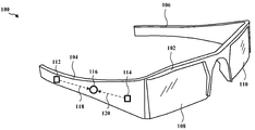
[0005] Figure 1 is a diagram illustrating an optical device configured to display content.
[0006] FIG. 2 is a diagram illustrating an optical device configured to display content.
[0007] FIG. 3 is a diagram illustrating an optical device configured to display content.
[0008] FIG. 4 is a flow diagram of a method for controlling an optical device configured to display content.
[0009] FIG. 5 is a conceptual flow chart illustrating operation of different modules / means / components within an exemplary apparatus.
[0010] FIG. 6 is a diagram illustrating an example of a hardware implementation for an apparatus employing a processing system.
BRIEF DESCRIPTION OF THE DRAWINGS [0011] The following detailed description, taken in conjunction with the accompanying drawings, is intended as a description of various configurations and is not intended to represent only those configurations in which the concepts described herein may be practiced. The detailed description includes specific details for the purpose of providing a thorough understanding of the various concepts. However, it will be apparent to those skilled in the art that these concepts may be practiced without these specific details. In some instances, well known structures and components are shown in block diagram form in order to avoid obscuring those concepts.
[0012] Several aspects of an infrared non-contact gesture system will now be presented with reference to various apparatus and methods. These devices and methods will be described in the following detailed description and are incorporated into various blocks, modules, components, circuits, steps, processes, algorithms, etc. (collectively referred to as " In the accompanying drawings. These elements may be implemented using electronic hardware, computer software, or any combination thereof. Whether such elements are implemented as hardware or software depends upon the particular application and design constraints imposed on the overall system.
[0013] By way of example, an element, or any combination of elements, or any portion thereof, may be implemented using a "processing system" that includes one or more processors. Examples of processors include microprocessors, microcontrollers, digital signal processors (DSPs), field programmable gate arrays (FPGAs), programmable logic devices (PLDs), state machines, gated logic, discrete hardware circuits, And other suitable hardware configured to perform the various functions described throughout this disclosure. One or more processors in a processing system may execute software. The software may include instructions, instruction sets, code, code segments, program code, programs, subprograms, and the like, whether referred to or otherwise referred to as software, firmware, middleware, microcode, a hardware description language, Should be broadly interpreted to mean software modules, software modules, applications, software applications, software packages, routines, subroutines, objects, executables, execution threads, procedures,
[0014] Thus, in one or more of the exemplary embodiments, the functions described may be implemented in hardware, software, firmware, or any combination thereof. When implemented in software, the functions may be encoded or stored as one or more instructions or code on a computer-readable medium. Computer-readable media include computer storage media. The storage media may be any available media that can be accessed by a computer. By way of example, and not limitation, such computer-readable media can comprise a computer-readable medium such as RAM, ROM, EEPROM, CD-ROM or other optical disk storage, magnetic disk storage or other magnetic storage devices, Or any other medium which can be used to carry or store the code and which can be accessed by a computer. As used herein, a disk and a disc may be a compact disk (CD), a laser disk, an optical disk, a digital versatile disk (DVD), a floppy disk Discs and blu-ray discs, in which discs generally reproduce data magnetically, while discs reproduce data optically using lasers. Combinations of the above should also be included within the scope of computer-readable media.
[0015] FIG. 1 is a diagram illustrating an
[0016] In an aspect, the
[0017] In an aspect, with reference to FIG. 1, the UI may include a
[0018] Each signal generated by the
[0019] For example, the right swipe non-contact gesture may include a command to zoom out in a camera application or a map application, a command to select an item on the list from the top to the bottom in the media player application, A command to scroll down a page in an application, and / or a command to set focus on application icons, one from left to right, in the application menu. The left swipe non-contact gesture may include a command to zoom in on a camera application or a map application, a command to select an item on the list from bottom to top in the media player application, and / or a command for setting focus from right to left on application icons in the application menu. The center tap non-contact gesture may correspond to a command for exiting the current application. The front-tap non-contact gesture may include a command to take a picture in a camera application, a command to accept a chat request, a command to go to the next page in an e-book application, and / . The rear-tap non-contact gesture may include a command to save a photo in a camera application, a command to reject a chat request, a command to go to a previous page in an e-book application, and / Or the like.
In an aspect, the
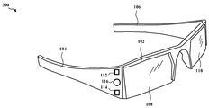
[0021] FIG. 2 is a diagram illustrating an
[0022] FIG. 3 is a diagram illustrating an
[0023] FIG. 4 is a flow diagram 400 of a method for controlling an optical device configured to display content. In
In an aspect, the
[0025] Each non-contact gesture may correspond to one or more commands. In one configuration, each signal generated by the
[0026] For example, a right swipe non-contact gesture may include a command to zoom out in a camera application or a map application, a command to select an item on the list from the top to bottom in the media player application, A command for scrolling down, and / or a command for setting focus on application icons, one from left to right, in the application menu. The left swipe non-contact gesture includes a command to zoom in on a camera application or a map application, a command to select an item on the list from bottom to top in the media player application, a command to scroll up the page in the e-book application, / RTI > < RTI ID = 0.0 > and / or < / RTI > one from the right to the left in the application menu. The center tap non-contact gesture may correspond to a command for exiting the current application. The front-tap non-contact gesture may include a command to take a picture in a camera application, a command to accept a chat request, a command to go to the next page in an e-book application, and / . The rear-tap non-contact gesture may include a command to save a photo in a camera application, a command to reject a chat request, a command to go to a previous page in an e-book application, and / Or the like.
[0027] At
[0028] Finally, at
[0029] FIG. 5 is a
FIG. 6 is a diagram illustrating an example of a hardware implementation for an apparatus 502 'using a
[0031] The
In one arrangement, the
[0033] The above-described means may include one or more of the aforementioned modules of the
[0034] It is understood that the particular order or hierarchy of steps within the described processes is exemplary of exemplary approaches. It is understood that, based on design preferences, a particular order or hierarchy of steps within the processes may be rearranged. Additionally, some steps may be combined or omitted. The appended method claims present elements of the various steps in a sample order and are not intended to be limited to the particular order or hierarchy presented.
[0035] The previous description is provided to enable any person of ordinary skill in the art to practice the various aspects described herein. Various modifications to these aspects will be readily apparent to those skilled in the art, and the generic principles defined herein may be applied to other aspects. Accordingly, the claims are not intended to be limited to the aspects shown herein but are to be accorded the widest scope consistent with the language of the claims, wherein references to singular elements are expressly referred to as "one and only one" Is intended to mean "one or more, " rather than" one and only one. &Quot; Unless specifically stated otherwise, the term "some" refers to one or more. All structural and functional equivalents to elements of the various aspects described throughout this disclosure which are known or later known to those skilled in the art are expressly incorporated herein by reference and are intended to be encompassed by the claims. Furthermore, nothing described herein is intended for public use, whether or not such disclosure is expressly recited in a claim. No claim element will be construed as a means plus function unless the element is expressly referred to as " means for "
Claims (24)
Generating at least one signal in response to a contactless gesture performed in proximity to an infrared proximity sensor located on the optical device, the non-contact gesture corresponding to a command;
Identifying the command using the at least one signal; And
And executing the command.
Wherein the infrared proximity sensor is located between at least a first infrared light emitting diode (IR LED) and a second infrared light emitting diode.
Wherein the non-contact gesture is at least one of a left swipe, a right swipe, an upward swipe, a downward swipe, a forward tap, a rear tab, and a center tap.
Wherein executing the command comprises performing a function for controlling at least one of the content and a graphical user interface (GUI).
Wherein the content is one of augmented reality information, an e-book, or a movie.
Wherein the non-contact gesture is performed at a front portion of the optical device or a side portion of the optical device.
Means for generating at least one signal in response to a non-contact gesture performed proximate to an infrared proximity sensor located on the optical device, the non-contact gesture corresponding to a command;
Means for identifying the command using the at least one signal; And
And means for executing the command.
Wherein the infrared proximity sensor is located between at least a first infrared light emitting diode (IR LED) and a second infrared light emitting diode.
Wherein the non-contact gesture is at least one of a left swipe, a right swipe, an upward swipe, a downward swipe, a forward tab, a rear tab, and a center tab.
Wherein the means for executing the command is configured to perform a function for controlling at least one of the content and a graphical user interface (GUI).
Wherein the content is one of augmented reality information, an e-book, or a movie.
Wherein the non-contact gesture is performed at a front portion of the optical device or a side portion of the optical device.
Processing system,
The processing system comprising:
Generating at least one signal in response to a non-contact gesture performed proximate to an infrared proximity sensor located on the optical device, the non-contact gesture corresponding to a command;
Identify the command using the at least one signal; And
Execute the above command
Wherein the optical device is configured to control the optical device.
Wherein the infrared proximity sensor is located between at least a first infrared light emitting diode (IR LED) and a second infrared light emitting diode.
Wherein the non-contact gesture is at least one of a left swipe, a right swipe, an upward swipe, a downward swipe, a forward tab, a rear tab, and a center tab.
Wherein the processing system is configured to execute the command by performing a function for controlling at least one of the content and a graphical user interface (GUI).
Wherein the content is one of augmented reality information, an e-book, or a movie.
Wherein the non-contact gesture is performed at a front portion of the optical device or a side portion of the optical device.
A computer-readable medium,
The computer-
Generating at least one signal in response to a non-contact gesture performed proximate to an infrared proximity sensor located on the optical device, the non-contact gesture corresponding to a command;
Identify the command using the at least one signal; And
Execute the above command
A computer program product comprising code for:
Wherein the infrared proximity sensor is located between at least a first infrared light emitting diode (IR LED) and a second infrared light emitting diode.
Wherein the non-contact gesture is at least one of a left swipe, a right swipe, an upward swipe, a downward swipe, a forward tab, a rear tab, and a center tab.
Wherein executing the command comprises performing a function for controlling at least one of the content and a graphical user interface (GUI).
Wherein the content is one of augmented reality information, an e-book, or a movie.
Wherein the non-contact gesture is performed at a front portion of the optical device or a side portion of the optical device.
Applications Claiming Priority (3)
| Application Number | Priority Date | Filing Date | Title |
|---|---|---|---|
| US13/692,949 US9977503B2 (en) | 2012-12-03 | 2012-12-03 | Apparatus and method for an infrared contactless gesture system |
| US13/692,949 | 2012-12-03 | ||
| PCT/US2013/071453 WO2014088847A1 (en) | 2012-12-03 | 2013-11-22 | Apparatus and method for an infrared contactless gesture system |
Publications (1)
| Publication Number | Publication Date |
|---|---|
| KR20150091487A true KR20150091487A (en) | 2015-08-11 |
Family
ID=49759580
Family Applications (1)
| Application Number | Title | Priority Date | Filing Date |
|---|---|---|---|
| KR1020157016847A KR20150091487A (en) | 2012-12-03 | 2013-11-22 | Apparatus and method for an infrared contactless gesture system |
Country Status (6)
| Country | Link |
|---|---|
| US (1) | US9977503B2 (en) |
| EP (1) | EP2926216A1 (en) |
| JP (1) | JP6271573B2 (en) |
| KR (1) | KR20150091487A (en) |
| CN (2) | CN110362205A (en) |
| WO (1) | WO2014088847A1 (en) |
Families Citing this family (10)
| Publication number | Priority date | Publication date | Assignee | Title |
|---|---|---|---|---|
| US9223136B1 (en) | 2013-02-04 | 2015-12-29 | Google Inc. | Preparation of image capture device in response to pre-image-capture signal |
| US20140232694A1 (en) * | 2013-02-19 | 2014-08-21 | Motorola Mobility Llc | Sensing Strip for Providing Touch and Gesture Controls |
| CN105204643A (en) * | 2015-09-28 | 2015-12-30 | 大连楼兰科技股份有限公司 | Gesture recognition method for intelligent glasses used in vehicle maintaining process |
| US20170220131A1 (en) * | 2016-02-03 | 2017-08-03 | Mediatek Inc. | Method for controlling operations of an electronic device through ambient light detection, and associated apparatus |
| US10353478B2 (en) * | 2016-06-29 | 2019-07-16 | Google Llc | Hover touch input compensation in augmented and/or virtual reality |
| CN107885313A (en) * | 2016-09-29 | 2018-04-06 | 阿里巴巴集团控股有限公司 | A kind of equipment exchange method, device and equipment |
| WO2018225081A1 (en) * | 2017-06-05 | 2018-12-13 | Symphony Limited | A gesture control system for evaporative air coolers |
| CN107463910A (en) * | 2017-08-09 | 2017-12-12 | 中国电子科技集团公司第二十八研究所 | Target identification augmented reality system based on GoogleGlass |
| CA3132557C (en) * | 2019-03-08 | 2023-05-23 | The Chamberlain Group Llc | Object detection system and method |
| CN114879898A (en) * | 2022-06-02 | 2022-08-09 | 湖北星纪时代科技有限公司 | Control method, device, equipment and storage medium |
Family Cites Families (33)
| Publication number | Priority date | Publication date | Assignee | Title |
|---|---|---|---|---|
| AUPQ582900A0 (en) | 2000-02-24 | 2000-03-16 | Silverbrook Research Pty Ltd | Printed media production |
| US20020036617A1 (en) * | 1998-08-21 | 2002-03-28 | Timothy R. Pryor | Novel man machine interfaces and applications |
| US6495832B1 (en) * | 2000-03-15 | 2002-12-17 | Touch Controls, Inc. | Photoelectric sensing array apparatus and method of using same |
| US20120188206A1 (en) * | 2001-11-02 | 2012-07-26 | Neonode, Inc. | Optical touch screen with tri-directional micro-lenses |
| US20070046643A1 (en) * | 2004-08-06 | 2007-03-01 | Hillis W Daniel | State-Based Approach to Gesture Identification |
| US7598949B2 (en) * | 2004-10-22 | 2009-10-06 | New York University | Multi-touch sensing light emitting diode display and method for using the same |
| US8599140B2 (en) * | 2004-11-17 | 2013-12-03 | International Business Machines Corporation | Providing a frustrated total internal reflection touch interface |
| US20070220108A1 (en) | 2006-03-15 | 2007-09-20 | Whitaker Jerry M | Mobile global virtual browser with heads-up display for browsing and interacting with the World Wide Web |
| DE102006020570A1 (en) | 2006-05-01 | 2007-11-08 | Mechaless Systems Gmbh | Optoelectronic device for detecting the position and / or movement of an object and associated method |
| WO2008093258A1 (en) * | 2007-01-29 | 2008-08-07 | Koninklijke Philips Electronics N.V. | Method and system for locating an object on a surface |
| IL183637A (en) * | 2007-06-04 | 2013-06-27 | Zvi Lapidot | Distributed head-mounted display |
| US8432372B2 (en) | 2007-11-30 | 2013-04-30 | Microsoft Corporation | User input using proximity sensing |
| US8957835B2 (en) | 2008-09-30 | 2015-02-17 | Apple Inc. | Head-mounted display apparatus for retaining a portable electronic device with display |
| WO2010062481A1 (en) * | 2008-11-02 | 2010-06-03 | David Chaum | Near to eye display system and appliance |
| US8294105B2 (en) | 2009-05-22 | 2012-10-23 | Motorola Mobility Llc | Electronic device with sensing assembly and method for interpreting offset gestures |
| US8344325B2 (en) * | 2009-05-22 | 2013-01-01 | Motorola Mobility Llc | Electronic device with sensing assembly and method for detecting basic gestures |
| KR20110047600A (en) | 2009-10-30 | 2011-05-09 | 삼성전자주식회사 | Electronic apparatus avaliable proximity sensing |
| WO2011097564A1 (en) | 2010-02-05 | 2011-08-11 | Kopin Corporation | Touch sensor for controlling eyewear |
| US20120194420A1 (en) * | 2010-02-28 | 2012-08-02 | Osterhout Group, Inc. | Ar glasses with event triggered user action control of ar eyepiece facility |
| WO2011106797A1 (en) | 2010-02-28 | 2011-09-01 | Osterhout Group, Inc. | Projection triggering through an external marker in an augmented reality eyepiece |
| US20120120103A1 (en) | 2010-02-28 | 2012-05-17 | Osterhout Group, Inc. | Alignment control in an augmented reality headpiece |
| US20110310005A1 (en) * | 2010-06-17 | 2011-12-22 | Qualcomm Incorporated | Methods and apparatus for contactless gesture recognition |
| CN101890719B (en) | 2010-07-09 | 2015-06-03 | 中国科学院深圳先进技术研究院 | Robot remote control device and robot system |
| KR101431366B1 (en) | 2010-07-20 | 2014-08-19 | 엠파이어 테크놀로지 디벨롭먼트 엘엘씨 | Augmented reality proximity sensing |
| US8531355B2 (en) | 2010-07-23 | 2013-09-10 | Gregory A. Maltz | Unitized, vision-controlled, wireless eyeglass transceiver |
| CN102622132A (en) | 2011-02-01 | 2012-08-01 | 纬创资通股份有限公司 | Electronic device with non-touch interface and not-touch control method |
| US8928741B2 (en) * | 2011-03-31 | 2015-01-06 | Sony Corporation | 3-D controller system for legacy TV |
| US20120312956A1 (en) * | 2011-06-11 | 2012-12-13 | Tom Chang | Light sensor system for object detection and gesture recognition, and object detection method |
| US8199126B1 (en) | 2011-07-18 | 2012-06-12 | Google Inc. | Use of potential-touch detection to improve responsiveness of devices |
| US8319746B1 (en) * | 2011-07-22 | 2012-11-27 | Google Inc. | Systems and methods for removing electrical noise from a touchpad signal |
| US8217856B1 (en) | 2011-07-27 | 2012-07-10 | Google Inc. | Head-mounted display that displays a visual representation of physical interaction with an input interface located outside of the field of view |
| US20130106686A1 (en) * | 2011-10-31 | 2013-05-02 | Broadcom Corporation | Gesture processing framework |
| US8823643B1 (en) * | 2012-07-09 | 2014-09-02 | Bill Biswell | Optical computer input controller device |
-
2012
- 2012-12-03 US US13/692,949 patent/US9977503B2/en active Active
-
2013
- 2013-11-22 WO PCT/US2013/071453 patent/WO2014088847A1/en active Application Filing
- 2013-11-22 KR KR1020157016847A patent/KR20150091487A/en active IP Right Grant
- 2013-11-22 CN CN201910639338.4A patent/CN110362205A/en active Pending
- 2013-11-22 CN CN201380062601.9A patent/CN104854536A/en active Pending
- 2013-11-22 EP EP13803370.9A patent/EP2926216A1/en not_active Withdrawn
- 2013-11-22 JP JP2015545126A patent/JP6271573B2/en not_active Expired - Fee Related
Also Published As
| Publication number | Publication date |
|---|---|
| US20140152539A1 (en) | 2014-06-05 |
| WO2014088847A1 (en) | 2014-06-12 |
| CN110362205A (en) | 2019-10-22 |
| JP2016505939A (en) | 2016-02-25 |
| US9977503B2 (en) | 2018-05-22 |
| EP2926216A1 (en) | 2015-10-07 |
| JP6271573B2 (en) | 2018-01-31 |
| CN104854536A (en) | 2015-08-19 |
Similar Documents
| Publication | Publication Date | Title |
|---|---|---|
| US9977503B2 (en) | Apparatus and method for an infrared contactless gesture system | |
| US11366515B2 (en) | Apparatus and method for controlling an augmented reality device | |
| US10976831B2 (en) | Interactive system and device with gesture recognition function | |
| US8655416B2 (en) | User interface for a portable device including detecting close proximity of an ear to allow control of an audio application with a touchscreen | |
| US20220012283A1 (en) | Capturing Objects in an Unstructured Video Stream | |
| KR20230017299A (en) | Assistant device mediation using wearable device data | |
| KR20190087197A (en) | Electronic apparatus, method for controlling thereof and the computer readable recording medium | |
| KR102005406B1 (en) | Dispaly apparatus and controlling method thereof | |
| TW201709022A (en) | Non-contact control system and method | |
| KR20150134252A (en) | Dispaly apparatus, remote controll apparatus, system and controlling method thereof | |
| US11074024B2 (en) | Mobile device for interacting with docking device and method for controlling same | |
| CN111367401A (en) | Man-machine interface board and control method, monitoring unit and storage medium thereof | |
| CN113110770B (en) | Control method and device | |
| US20230185370A1 (en) | Electronic apparatus, method for controlling electronic apparatus, and storage medium | |
| KR20240053372A (en) | Apparatus and method for recommending customized functions in an electronic device | |
| KR20240009024A (en) | Apparatus for controlling roof lighting of vehicle and method thereof | |
| KR20240008735A (en) | System for controlling display of vehicle and method thereof | |
| US20170097656A1 (en) | Controlling a target device |
Legal Events
| Date | Code | Title | Description |
|---|---|---|---|
| A201 | Request for examination | ||
| E902 | Notification of reason for refusal | ||
| E701 | Decision to grant or registration of patent right |