KR20150086555A - Dabbing pulsed welding system and method - Google Patents
Dabbing pulsed welding system and method Download PDFInfo
- Publication number
- KR20150086555A KR20150086555A KR1020157018195A KR20157018195A KR20150086555A KR 20150086555 A KR20150086555 A KR 20150086555A KR 1020157018195 A KR1020157018195 A KR 1020157018195A KR 20157018195 A KR20157018195 A KR 20157018195A KR 20150086555 A KR20150086555 A KR 20150086555A
- Authority
- KR
- South Korea
- Prior art keywords
- phase
- welding
- during
- short circuit
- peak
- Prior art date
Links
Images


Classifications
-
- B—PERFORMING OPERATIONS; TRANSPORTING
- B23—MACHINE TOOLS; METAL-WORKING NOT OTHERWISE PROVIDED FOR
- B23K—SOLDERING OR UNSOLDERING; WELDING; CLADDING OR PLATING BY SOLDERING OR WELDING; CUTTING BY APPLYING HEAT LOCALLY, e.g. FLAME CUTTING; WORKING BY LASER BEAM
- B23K9/00—Arc welding or cutting
- B23K9/10—Other electric circuits therefor; Protective circuits; Remote controls
- B23K9/1006—Power supply
- B23K9/1012—Power supply characterised by parts of the process
-
- B—PERFORMING OPERATIONS; TRANSPORTING
- B23—MACHINE TOOLS; METAL-WORKING NOT OTHERWISE PROVIDED FOR
- B23K—SOLDERING OR UNSOLDERING; WELDING; CLADDING OR PLATING BY SOLDERING OR WELDING; CUTTING BY APPLYING HEAT LOCALLY, e.g. FLAME CUTTING; WORKING BY LASER BEAM
- B23K9/00—Arc welding or cutting
- B23K9/09—Arrangements or circuits for arc welding with pulsed current or voltage
- B23K9/091—Arrangements or circuits for arc welding with pulsed current or voltage characterised by the circuits
- B23K9/092—Arrangements or circuits for arc welding with pulsed current or voltage characterised by the circuits characterised by the shape of the pulses produced
-
- B—PERFORMING OPERATIONS; TRANSPORTING
- B23—MACHINE TOOLS; METAL-WORKING NOT OTHERWISE PROVIDED FOR
- B23K—SOLDERING OR UNSOLDERING; WELDING; CLADDING OR PLATING BY SOLDERING OR WELDING; CUTTING BY APPLYING HEAT LOCALLY, e.g. FLAME CUTTING; WORKING BY LASER BEAM
- B23K9/00—Arc welding or cutting
- B23K9/10—Other electric circuits therefor; Protective circuits; Remote controls
- B23K9/1006—Power supply
- B23K9/1043—Power supply characterised by the electric circuit
Abstract
펄스 용접 방식은 다빙 위상(74)이 뒤따르는 피크 위상(72)을 포함하되, 피크 위상에서 에너지는 전극과 용접 퍼들로 부가되고 용융 볼은 전극으로부터 분리되기 시작하며 다빙 위상에서 전류가 현저하게 감소되어 에너지를 거의 또는 전혀 부가함이 없이 볼을 용접 퍼들 내에 위치시킨다. 결과적인 단락 회로는 클리어되며 시스템은 배경 위상(70)을 진행한다. 다빙 위상 내에서의 전류는 배경 위상 동안의 전류보다 낮다. 공정은 특히 특정 용접 와이어를 위하여 적합할 수 있으며 그리고 특히 코어 와이어와 함께 사용하는 것에 아주 적합하다. 다빙 위상은 이러한 와이어의 피복에 전달될 보다 낮은 에너지를 고려하며, 그리고 각 펄스 사이클 후에 아크 길이를 재설정한다. The pulse welding scheme includes a peak phase 72 followed by a frozen phase 74 in which energy is added to the electrode and the weld puddle and the molten ball begins to separate from the electrode and the current in the frozen phase is significantly reduced Thereby placing the ball in the welding puddle with little or no additional energy. The resulting short circuit is cleared and the system proceeds in the background phase 70. The current in the falling phase is lower than the current during the background phase. The process may be particularly suitable for particular welding wires and is particularly well suited for use with core wires. The falling phase takes into account the lower energy to be delivered to the coating of such wire, and resets the arc length after each pulse cycle.

Description
본 출원은, 모든 의도로 본 명세서에서 참조로 그 전체 내용이 인용되는, 2012년 12월 12일자로 출원된 "다빙 펄스 용접 시스템 및 방법(Dabbing Pulsed Welding System and Method)"란 명칭의 미국 특허가출원 제61/736,393호의 정규특허출원이다.This application claims the benefit of US Provisional Patent Application entitled " Dabbing Pulsed Welding System and Method " filed December 12, 2012, the entirety of which is incorporated herein by reference in its entirety 61 / 736,393. ≪ / RTI >
본 발명은 용접기에 관한 것으로서, 특히 와이어가 용접 토치로부터 전진함에 따라 따라 펄스 파형이 용접 와이어에 인가되는 용접 작업을 수행하도록 구성된 용접기에 관한 것이다.The present invention relates to a welder, and more particularly to a welder configured to perform a welding operation in which a pulse waveform is applied to a welding wire as the wire advances from the welding torch.
광범위한 용접 시스템 및 용접 제어 방안이 다양한 용도로 구현되어 있다. 연속 용접 작업에서, 금속 불활성 가스(MIG) 기법은 용접 토치로부터의 불활성 가스에 의하여 보호된 용접 와이어의 공급에 의해 연속적 용접 비드의 형성을 허용한다. 전력이 용접 와이어에 인가되고 회로가 공작물을 통해 회로가 완성되어, 원하는 용접부를 형성하도록 와이어와 공작물을 용융시키는 아크를 유지하게 된다.A wide range of welding systems and welding controls are implemented for various applications. In a continuous welding operation, the metal inert gas (MIG) technique allows the formation of continuous weld beads by the supply of welding wire protected by an inert gas from the welding torch. Power is applied to the welding wire and the circuit is completed through the workpiece to maintain the arc that melts the wire and workpiece to form the desired weld.
발전된 형태의 MIG 용접은 용접 전력 공급 장치에서의 펄스 전력의 발생을 기초로 한다. 즉, 전력 공급 장치의 제어 회로가 전류 및/또는 전압 펄스를 통제하여 용접 와이어로부터의 금속 액적(metal droplets)의 형성 및 용착을 조절하고, 용융지(weld pool)의 원하는 가열 및 냉각 프로파일을 유지하고, 그리고 와이어와 용융지 간의 단락(shorting)을 제어하는 등의 다양한 펄스식 방안이 수행된다.The advanced form of MIG welding is based on the generation of pulse power in the welding power supply. That is, the control circuit of the power supply controls current and / or voltage pulses to regulate the formation and deposition of metal droplets from the welding wire and maintains the desired heating and cooling profile of the weld pool And controlling the shorting between the wire and the fusing paper.
많은 용례에서 매우 효과적이지만, 이러한 펄스식 방안은 문제점을 겪을 수 있다. 예를 들어, 전달 모드에 따라 공정은 이동 속도를 제한하거나, (용접된 공작물의 시기 적절한 세척을 요구하는) 과도한 스패터(spatter)를 생성하거나, 최적에 미치지 못하는 침투를 제공하거나, 이들 또는 기타 효과의 임의의 조합을 초래할 수 있다. 또한, 스프레이 모드의 재료 전달로 작동하는 것과 같은 임의의 펄스식 공정은 특정 용례에 대해서는 과도하게 고온으로 될 수 있다. 단락 회로식 공정 등의 기타 공정에서는 보다 저온으로 될 수 있지만, 이는 또한 스패터나 기타 원치 않는 효과를 야기할 수 있다. While very effective in many applications, such a pulse scheme can suffer problems. For example, depending on the mode of delivery, the process may include limiting the speed of travel, creating excessive spatter (requiring timely cleaning of welded workpieces), providing non-optimal penetration, May result in any combination of effects. In addition, any pulsed process, such as operating in the spray mode of material delivery, can become excessively hot for certain applications. Other processes, such as short circuit processes, can be colder, but this can also cause spatter or other undesirable effects.
더욱이, 소정 용접 상황에서 그리고 소정 용접 전극에 있어서, 전극과 공작물 간에 주기적 단락 회로를 실현하도록 조절된 펄스식 용접 공정은 용접부에 과도한 에너지를 추가할 수 있다. 예를 들어, 코어드 와이어 전극(cored wire electrode)에 있어서, 그 전극은, 특히 용접 전류가 솔리드 와이어보다 용이하게 용융될 수 있는 와이어 피복을 통해 흐르는 경향이 있는 만큼, 와이어에 가해지는 과도한 전류에 의하여 가열될 수 있다. 결과적으로 아크가 넓어질(flaring) 수(길어질 수) 있다. 그러나, 갭을 잇고, 용락(burn-through)을 줄이고 그리고 이동 속도를 증가시키기 위하여 아크 길이를 최소한으로 유지하는 것이 바람직할 수 있다. 불행하게도, 이는 와이어를 진행 중인 용접 퍼들(weld puddle)에 대해 단락시키고, 또한 단락 회로를 클리어하기 위하여 추가의 전류를 필요로 하고 이는 또한 코어드 와이어 피복의 가열을 다시 야기하고 아크가 넓어지게 한다.Moreover, in certain welding situations and at certain welding electrodes, a pulsed welding process adjusted to realize a cyclic short circuit between the electrode and workpiece can add excessive energy to the weld. For example, for a cored wire electrode, the electrode is subject to excessive current applied to the wire, particularly as the welding current tends to flow through the wire sheath, which can be melted more easily than the solid wire . As a result, the arc may become flaring (can be lengthened). However, it may be desirable to keep the arc length to a minimum in order to join the gap, reduce the burn-through and increase the travel speed. Unfortunately, this shorts the wire to an ongoing weld puddle and also requires additional current to clear the short circuit, which again causes heating of the cored wire jacket and widening of the arc .
따라서, 용접 품질과 유연성을 향상시키면서 펄스식 파형 방안으로 용접을 가능하게 하는 개선된 용접 전략이 필요하다.Thus, there is a need for an improved welding strategy that enables welding in a pulsed wave form while improving weld quality and flexibility.
본 발명은 이러한 요구에 부응하도록 설계된 용접 시스템을 제공한다. 예시적인 실시형태에 따르면, 용접 시스템은, 피크 위상, 그 직후의 다빙 위상(dabbing phase) 및 이에 후속한 배경 위상(backgroudn phase)를 포함한 제어 파형을 제공하도록 구성된 처리 회로; 및 제어 파형에 기초하여 용접 전력 출력을 제공하도록 구성된 전력 변환 회로를 포함한다.The present invention provides a welding system designed to meet this need. According to an exemplary embodiment, the welding system includes a processing circuit configured to provide a control waveform including a peak phase, a dabbing phase immediately thereafter, and a subsequent backgroud phase; And a power conversion circuit configured to provide a welding power output based on the control waveform.
본 발명은 또한, 하나의 양태에 따라 피크 위상, 그 직후의 다빙 위상 및 이에 후속한 배경 위상를 포함하는 용접 전력 출력을 위한 파형을 발생시키고 이 제어 파형에 기초하여 입력 전력을 용접 전력으로 변환시키는 것과 같은 용접 방법을 제공한다.The present invention also relates to a method of generating a waveform for a welding power output comprising a peak phase, a double-frozen phase immediately thereafter and a subsequent background phase in accordance with one embodiment, and converting input power to welding power based on the control waveform Provide the same welding method.
도 1은 본 기술의 양태에 따른 펄스식 용접 작업을 수행하도록 와이어 공급 장치에 결합된 전력 공급 장치를 설명하는 예시적인 MIG 용접 시스템의 개략적인 도면.
도 2는 도 1에 도시된 형태의 용접 전력 공급 장치를 위한 예시적인 제어 회로 요소의 개략적인 도면.
도 3은 본 기술에 따라 용융 금속을 용접 전극으로부터 용접 퍼들로 다빙(dabbing)하기 예시적인 파형의 도시적인 도면.
도 4는 실제 실행 중에 그러한 파형의 일련의 펄스에서의 전압과 전류의 도시적인 도면.
도 5는 그러한 용접 방안을 수행하는 소정 제어 로직을 도시한 플로우 차트.
도 6은 본 기술에 따라 용접 전극에서 용접 퍼들로 용융 금속을 다빙하기 위한 다른 예시적인 파형의 도시적인 도면.
도 7은 도 6의 용접 방안을 실행하는 데 있어 소정 제어 로직을 도시한 플로우 챠트.
도 8은 본 기술에 따른 전력 오프 신호를 생성하는 소정 제어 로직을 도시한 플로우 챠트.BRIEF DESCRIPTION OF THE DRAWINGS Figure 1 is a schematic illustration of an exemplary MIG welding system illustrating a power supply coupled to a wire feeder to perform a pulsed welding operation in accordance with aspects of the present technique;
Figure 2 is a schematic diagram of an exemplary control circuit element for a welding power supply of the type shown in Figure 1;
3 is an illustration of an exemplary waveform for dabbing a molten metal from a welding electrode into a welding puddle according to the present technique;
4 is a diagrammatic illustration of voltages and currents in a series of pulses of such a waveform during actual execution;
5 is a flow chart illustrating certain control logic for performing such a welding strategy.
6 is an illustrative diagram of another exemplary waveform for melting molten metal from a welding electrode to a welding puddle according to the present technique;
7 is a flow chart illustrating certain control logic in executing the welding strategy of FIG. 6;
8 is a flow chart illustrating certain control logic for generating a power off signal in accordance with the present technique;
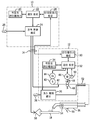
도면으로 돌아가 도 1을 먼저 참고하면, 예시적인 용접 시스템은 전도체 또는 도관(14)을 통해 서로 결합된 전력 공급 장치(10)와 와이어 공급 장치(12)를 포함하는 것으로 도시되어 있다. 도시된 실시예에서, 전력 공급 장치(10)는 와이어 공급 장치(12)와는 별개로 이루어져, 와이어 공급 장치가 전력 공급 장치로부터 얼마간 거리를 두고 떨어져 용접 위치 근처에 위치될 수 있다. 그러나, 일부 실시형태에서 와이어 공급 장치는 전력 공급 장치와 일체로 될 수 있다는 것은 이해할 것이다. 이러한 경우, 도관(14)은 시스템 내부에 있을 것이다. 와이어 공급 장치가 전력 공급 장치와는 별개로 이루어진 실시예에서, 전력 공급 장치로부터 와이어 공급 장치로 전력 및 가스가 제공될 수 있게 하고 또한 두 장치 간에 데이터 교환이 가능하도록 하기 위해, 단자가 전력 공급 장치 및 와이 공급 장치에 마련되어 전도체 또는 도관(14)를 그 시스템에 결합될 수 있도록 된다. 1, an exemplary welding system is shown to include a
시스템은 용접 토치(16)에 와이어, 전원 및 보호 가스를 제공하도록 설계된다. 당업자라면, 용접 토치는 수많은 다양한 타입으로 이루어질 수 있으며, 통상적으로 2 개 이상의 금속편을 결합하도록 용접부가 형성될 공작물(18)에 인접한 위치로 용접 와이어 및 가스의 공급을 가능하게 한다는 점을 이해할 것이다. 통상, 제2 전도체가 용접 공작물로 연장하여, 전력 공급 장치와 공작물 간에 전기 회로를 완성한다.The system is designed to provide wire, power, and protective gas to the
시스템은 특히 전력 공급 장치 상에 제공된 작업자 인터페이스(20)를 통하여 작업자가 데이터 세팅을 선택할 수 있도록 설계된다. 작업자 인터페이스는 전형적으로 전력 공급 장치의 전면판에에 합체되어, 용접 공정, 사용될 와이어의 종류, 전압 및 전류 세팅 등을 선택할 수 있게 한다. 특히, 시스템은 다양한 강, 알루미늄 또는 토치를 통해 안내되는 다른 용접 와이어를 사용한 MIG 용접을 가능하게 하도록 설계된다. 그러한 용접 세팅은 전력 공급 장치 내의 제어 회로(22)에 전송된다. 시스템은 특히 코어드 전극과 같은 임의의 전극 형태를 위해 설계된 용접 방안을 실행하도록 조정될 수 있다.The system is specifically designed to allow the operator to select data settings via the
이하에서 보다 상세하게 설명될 제어 회로는 원하는 용접 작업을 수행하도록 용접 와이어에 인가될 용접 전력 출력의 발생을 제어하도록 작동한다. 현재 고려된 소정 실시예에서, 예를 들어 제어 회로는 용접부 또는 전극에 과도한 에너지를 부가하지 않고 진행하는 용접 퍼들로의 용융 금속의 단락 회로 전달(short circuit transfer)을 "다빙" 또는 촉진하는 펄스 MIG 용접 방안을 조절하도록 될 수 있다. "단락 회로" 모드에서, 용융 금속의 액적은 용접 아크에 의한 가열의 영향 하에서 용접 와이어 상에 형성되며, 이들 액적은 와이어와 액적 그리고 용융지 간의 접촉 또는 단락 회로에 의하여 주기적으로 용융지로 전달된다. "펄스식 용접" 또는 "펄스식 MIG 용접"은 진행하는 용접 퍼들로의 금속 액적의 용착을 제어하도록 하는 등을 위해 펄스형 전력 파형이 발생되는 기술을 가리킨다. 본 발명의 특정 실시예에서, "하이브리드 펄스-단락 회로 용접 방안(Hybrid Pulsed-Short Circuit Welding Regime)"란 명칭으로 Hutchison 등에 의해 2012년 10월 18일자로 출원되고 본 명세서에서 참조로 인용되는 미국 특허출원 제13/655,174호에 기재된 바와 같이, "하이브리드" 전달 모드 형태로, 단락 회로 용접과 스프레이 용접의 특징 모두를 갖는, 펄스를 발생시키는 특수한 펄스식 용접 방안이 실행될 수도 있다.The control circuit, which will be described in more detail below, operates to control the generation of the welding power output to be applied to the welding wire to perform the desired welding operation. In some presently contemplated embodiments, for example, the control circuit may include a pulse MIG " kicking "or facilitating a short circuit transfer of the molten metal to the welding puddle proceeding without adding excessive energy to the weld or electrode The welding plan can be adjusted. In the "short circuit" mode, a droplet of molten metal is formed on the welding wire under the influence of heating by a welding arc, and these droplets are periodically transferred to the fusing paper by a contact or short circuit between the wire and the droplet and the fusing paper. "Pulsed Weld" or "Pulsed MIG Weld" refers to a technique in which a pulsed power waveform is generated, such as to control the deposition of metal droplets into an advancing weld puddle. In a particular embodiment of the present invention, the term " Hybrid Pulsed-Short Circuit Welding Regime ", filed October 18, 2012 by Hutchison et al., And incorporated herein by reference, As described in the application Ser. No. 13 / 655,174, a special pulsed welding scheme may be implemented that generates pulses, both in the form of a "hybrid" delivery mode, with both short circuit welding and spray welding characteristics.
따라서 제어 회로는 전력 변환 회로(24)에 결합된다. 이 전력 변환 회로는 궁극적으로 토치에서 용접 와이어에 인가될 펄스 파형과 같은 출력 전력을 생성하도록 된다. 초퍼, 부스트 회로, 벅 회로(buck circuit), 인버터, 컨버터 등을 포함하는 다양한 전력 변환 회로가 이용될 수 있다. 이러한 회로의 구성은 당업계에에서 그리고 그 자체가 대체로 알려진 형태일 수 있다. 전력 변환 회로(24)는 화살표 26에 의하여 지시된 바와 같이 전력원에 결합된다. 엔진 구동식 발전기에 으해 발생된 전력, 배터리, 연료 전지 또는 기타 대안적인 전원 등과 같은 다른 전력 소스가 사용될 수 있지만, 전력 변환 회로(24)에 인가되는 전력은 전력망에서 얻어질 수 있다. 마지막으로, 도 1에 도시된 전력 공급 장치는 제어 회로(22)가 와이어 공급 장치(12)와 신호를 교환하도록 설계된 인터페이스 회로(28)를 포함한다.Thus, the control circuit is coupled to the
와이어 공급 장치(12)는 인터페이스 회로(28)와 결합된 보조 인터페이스 회로(30)를 포함한다. 일부 실시예에서, 두 요소들 모두에 멀티-핀 인터페이스가 마련되고 멀티-도전체 케이블이 인터페이스 회로들 사이에서 연장하여, 와이어 공급 속도, 공정, 선택된 전류, 전압 또는 전력 레벨 등과 같은 정보가 전력 공급 장치(10)와 와이어 공급 장치(12) 중 어느 하나 또는 둘 모두에서 세팅될 수 있도록 할 수 있다.The
와이어 공급 장치(12)는 또한 인터페이스 회로(30)에 결합된 제어 회로(32)를 포함한다. 이하에서 더 충분하게 설명될 바와 같이, 제어 회로(32)는 작업자의 선택에 따라 와이어 공급 속도가 제어될 수 있게 하고 또한 그 세팅이 인터페이스 회로를 통해 전력 공급 장치에 피드백될 수 있게 한다. 제어 회로(32)는 하나 이상의 용접 파라미터의 선택, 특히 와이어 공급 속도의 선택이 가능한 와이어 공급 장치 상의 작업자 인터페이스(34)에 결합된다. 작업자 인터페이스는 또한 공정, 이용된 와이어 종류, 전류, 전압 또는 전력 세팅 등의 용접 파라미터의 선택을 허용할 수도 있다. 제어 회로(32)는 또한 토치로의 보호 가스의 흐름을 조절하는 가스 제어 밸브(36)에 결합된다. 일반적으로, 이러한 가스는 용접시 제공되는 것으로, 용접 직전에 그리고 용접에 뒤이어 짧은 시간 동안에 켜진다. 가스 제어 밸브(36)에 가해진 가스는 통상적으로 도면 부호 38로 나타낸 바와 같이 압축 보틀 형태로 제공된다.The
와이어 공급 장치(12)는 제어 회로(36)의 제어 하에서 용접 토치로 이에 의해 용접 부위로 와이어를 공급하는 요소를 포함한다. 예를 들어, 용접 와이어의 하나 이상의 스풀(40)이 와이어 공급 장치 내에 수용된다. 용접 와이어(42)는 스풀에서 풀려져 점차 토치로 공급된다. 스풀은 클러치(44)와 결합될 수 있는 데, 그 클러치는 와이어를 토치에 공급하려 할 때에 스풀을 해방시키게 된다. 클러치는 또한 스풀의 자유로운 회전을 방지하기 위해 최소한의 마찰 수준을 유지하도록 조절될 수 있다. 공급 롤러(48)와 맞물리는 공급 모터(46)가 마련되어, 와이어 공급 장치로부터의 와이어를 토치를 향해 밀게 된다. 실제로 롤러(48) 중 하나는 모터에 기계적으로 결합되며 모터에 의하여 회전하여 와이어 공급 장치로부터 와이어를 구동하는 반면에, 상대 롤러는 와이어를 향해 압박되어, 2개의 롤러와 와이어 간의 양호한 접촉을 유지한다. 일부 시스템은 이러한 형태의 다수의 롤러를 포함할 수 있다. 마지막으로, 모터(46), 롤러(48) 또는 다른 관련된 요소의 속도를 검출하여 실제 와이어 공급 속도를 표시하도록 타코메터(50)가 마련될 수 있다. 타코메터로부터의 신호는 이하에서 설명될 바와 같은 캘리브레이션 등을 제어 회로(36)로 피드백된다.The
다른 시스템 구성 및 입력 체계 또한 실행될 수 있다는 점에 유의해야 한다. 예를 들어, 용접 와이어는 벌크 저장 컨테이너(예를 들어, 드럼)로부터 또는 와이어 공급 장치 밖의 하나 이상의 스풀로부터 공급될 수 있다. 마찬가지로, 스풀이 용접 토치 상에 또는 용접 토치 근처에 배치된 "스풀 건(spool gun)"으로부터 와이어가 공급될 수 있다. 본 명세서에서 언급하는 바와 같이, 와이어 공급 속도 세팅은 와이어 공급 장치 상의, 전력 공급 장치의 작업자 인터페이스(20) 상의, 또는 이들 둘 모두 상의 작업자 입력부(34)를 통하여 입력될 수 있다. 용접 토치 상에서 와이어 공급 속도 조절부를 갖는 시스템에서, 이는 설정을 위하여 사용된 입력부일 수 있다.It should be noted that other system configurations and input schemes may also be implemented. For example, the welding wire may be supplied from a bulk storage container (e.g., a drum) or from one or more spools outside the wire feeder. Similarly, a wire can be fed from a "spool gun" in which a spool is placed on or near the welding torch. As referred to herein, the wire feed rate setting can be entered via the
전력 공급 장치로부터의 전력은 통상 일반적인 방식으로 용접 케이블(52)을 통하여 와이어로 인가된다. 마찬가지로, 보호 가스가 와이어 공급 장치와 용접 케이블(52)을 통하여 공급된다. 용접 작업 동안에, 와이어는 용접 케이블 재킷을 통과해 토치(16)를 향하여 전진하다. 토치 내에는 추가적 견인 모터(54: pull motor)가 특히 알루미늄 용접 와이어를 위해 관련 구동 롤러와 함께 마련될 수 있다. 이하에서 더 상세하게 설명될 바와 같이 원하는 와이어 공급 속도를 제공하기 위하여 모터(54)는 조절된다. 토치 상의 트리거 스위치(56)는 와이어 공급 장치로 피드백되고 그리고 와이어 공급 장치로부터 전력 공급 장치로 피드백되는 신호를 제공하여 작업자에 의하여 용접 공정이 시작되고 종료될 수 있게 한다. 즉, 트리거 스위치의 누름에 따라 가스 흐름이 시작되고, 와이어가 앞으로 전진하며, 전력이 용접 케이블(52)에 인가되고 토치를 통하여 전진하는 용접 와이어로 인가된다. 이 과정은 또한 이하에서 더욱 상세하게 설명된다. 마지막으로, 작업 중에 용접 아크를 유지하기 위하여 공작물 케이블과 클램프(58)는 전력 공급 장치로부터 용접 토치, 전극(와이어) 그리고 공작물을 통과하는 전기 회로를 완성하게 할 수 있다.The power from the power supply is typically applied to the wire through the
와이어 공급 속도가 작업자에 의하여 "설정"될 수 있는 반면에, 제어 회로의 명령에 따른 실제 속도는 일반적으로 용접 동안에 다양한 이유로 달라질 것이다. 예를 들어, "런 인(run in)"(아크 시작을 위한 와이어의 초기 공급)을 위한 자동화된 알고리즘은 설정 속도로부터 유도된 속도를 사용할 수 있다. 마찬가지로, 와이어 공급 속도의 다양한 선형적 증가 및 감소가 용접 중에 지시될 수 있다. 다른 용접 공정은 용접부에 후속한 오목부를 채우도록 와이어 공급 속도가 변경되는 "크레이터링(cratering)" 단계를 필요로 할 수 있다. 더욱이, 펄스식 용접 방안에서, 와이어 공급 속도는 정기적으로 또는 주기적으로 달라질 수 있다.While the wire feed rate can be "set" by the operator, the actual speed in accordance with the command of the control circuit will generally vary for various reasons during welding. For example, an automated algorithm for "run in" (initial supply of wire for arc start) may use a velocity derived from a set velocity. Likewise, various linear increases and decreases in the wire feed rate can be indicated during welding. Other welding processes may require a "cratering" step in which the wire feed rate is changed to fill the subsequent recesses in the weld. Moreover, in a pulsed welding approach, the wire feed rate may vary periodically or periodically.
도 2는 도 1에 도시된 형태의 시스템에서 기능하도록 설계된 제어 회로(22)를 위한 예시적인 실시예를 도시한다. 도면에서 도면 부호 60으로 지시된 전체 회로는 위에서 설명된 작업자 인터페이스(20), 그리고 와이어 공급 장치, 용접 토치 및 다양한 센서 및/또는 액츄에이터와 같은 하류 구성 요소 내외로의 파라미터의 전달을 위한 인터페이스 회로(28)를 포함한다. 회로는 용접 계획을 실행하너 그 용접 계획에서 구현될 파형을 위한 연산을 행하는 등을 위해 설계된 하나 이상의 주문형 또는 범용 프로세서를 포함할 수 있는 처리 회로(62) 등을 포함한다. 처리 회로는 구동 회로(64)와 관련이 있으며, 이 구동 회로는 처리 회로로부터의 제어 신호를 전력 변환 회로(24)의 전원 전자 스위치로 인가되는 구동 신호로 변환한다. 일반적으로 구동 회로는 처리 회로로부터의 이러한 제어 신호에 응답하여 전력 변환 회로가 본 명세서에서 설명된 형태의 펄스 용접 방안을 위한 제어된 파형을 발생시키는 것을 허용한다. 처리 회로(62)는 또한 실행될 용접 방안을 제공하기 위한, 용접 변수를 저장하기 위한, 용접 세팅을 저장하기 위한, 그리고 에러 로그를 저장하기 위한 것과 같은 한 종류 이상의 영구적인 그리고 일시적인 데이터 저장 장치로 이루어질 수 있는 메모리 회로(66)와 협력할 수 있다.FIG. 2 shows an exemplary embodiment for a
용접을 위한 특정 상태 기계의 보다 상세한 설명이, 예를 들어 2001년 9월 19일자로 Holverson 등에 허여된 "상태 기반 컨트롤러를 갖는 용접형 전력 공급 장치(Welding-Type Power Supply With A State-Based Controller)"란 명칭의 미국특허 제6,747,247호; 2004년 5월 7일자로 Holverson 등에 허여된, "상태 기반 컨트롤러를 갖는 용접형 전력 공급 장치(Type Power Supply With A State-Based Controller)"라는 명칭의 미국특허 제7,002,103호; 2006년 2월 3일자로 Holverson 등에 허여된, "상태 기판 컨트롤러를 갖는 용접형 전력 공급 장치(Welding-Type Power Supply With A State-Based Controller)"라는 명칭의 미국특허 제7,307,240호; 및 2001년 9월 19일자로 Davidson 등에 허여된, "구성 요소들 사이의 네트워크와 다단계 메시징을 갖는 용접형 시스템(Welding-Type System With Network And Multiple Level Messaging Between Components)"라는 명칭의 미국특허 제6,670,579호에 제공되며, 이들 특허 문헌은 본 명세서에서 참고로 인용된다. A more detailed description of a particular state machine for welding may be found, for example, in Welding-Type Power Supply with State-Based Controller with Holsteron et al., Issued September 19, 2001, Quot; U.S. Patent No. 6,747,247; U.S. Patent No. 7,002,103 entitled " Type Power Supply With A State-Based Controller "issued to Holverson et al. On May 7, 2004; U.S. Patent No. 7,307,240 entitled " Welding-Type Power Supply With A State-Based Controller " issued to Holverson et al. On Feb. 3, 2006; And U.S. Patent No. 6,670,579 entitled " Welding-Type System With Network And Multiple Level Messaging Between Components "issued to Davidson et al. On Sep. 19, 2001, And these patents are incorporated herein by reference.
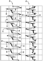
도 3은 전극에 인가된 용접 전류의 제어된 감소에 의하여 용접 전극으로부터의 용융된 금속이 용접 퍼들 내로 "다빙(dabbing)"되는 용접 기술을 위한 예시적인 파형을 도시한다. 이와 관련해서, "다빙"이란 용어는 비교적 과도한 단락은 방지되는 반면, 용융 금속이 이미 전극으로부터 분리되어 용접 퍼들로 전달되자 마자 매우 짧은 단락 회로가 형성될 수 있다는 점을 전달하고자 한 것이다. 따라서 보다 과도한 또는 보다 긴 단락 회로가 사용된다면 필요로 하였을 과도한 에너지를 추가하지 않고 금속이 전달된다. 그에 따른 용접 공정의 대부분의 사이클에서, 어떠한 특별한 단락 클리어링 시퀀스(short clearing sequence)는 필요로 하지 않은데, 이러한 시퀀스는 보다 긴 또는 과도한 단락 회로가 발생하는 경우에 실행되도록 프로그램되거나 준비되어 있을 수도 있다. "다빙"에 의해 금속이 전달되고 나면, 아크 길이는 사실상 재설정되어, 전극이 "보다 타이트하게 진행하게" 또는 용접 퍼들에 더 근접하게 진행하여 짧은 아크를 유지할 수 있게 한다. 위에서 설명된 바와 같이, 전압 및/전류 피크 후에 용융 금속(예를 들어, 금속의 볼)이 이미 분리되기 때문에 단락 회로를 클리어(clear)하기 위하여 전류가 거의 부가되지 않거나 또는 전류가 부가되지 않는다. 그 결과, 코어드 와이어가 사용될 때에 피복의 가열을 최소한으로 하면서 매우 낮은 전압의 아크(즉, 짧은 아크 길이)와 안정적인 아크가 얻어진다.3 shows an exemplary waveform for a welding technique in which the molten metal from a welding electrode is "dabbing" into a welding puddle by controlled reduction of the welding current applied to the electrode. In this connection, the term "falling glass" is intended to convey that a very short circuit can be formed as soon as molten metal has already been separated from the electrode and delivered to the welding puddle, while a relatively excessive short circuit is prevented. Thus, if more or more short circuits are used, the metal is transferred without adding excessive energy as would be needed. In most of the subsequent cycles of the welding process, no special short clearing sequence is needed, which may be programmed or prepared to be executed when a longer or excessive short circuit occurs. Once the metal has been transferred by "double-burping ", the arc length is substantially reset to allow the electrode to" travel more tightly "or to move closer to the weld puddle to maintain a short arc. As described above, since the molten metal (e.g., a metal ball) is already separated after voltage and / or current peaks, little or no current is added to clear the short circuit. As a result, very low voltage arcs (i.e. short arc lengths) and stable arcs are obtained while minimizing heating of the sheath when the cored wire is used.
전체적으로 도면 부호 68로 나타낸, 도 3에 도시된 파형은 배경 위상(70), 피크 위상(72) 및 다빙 위상(74; 짧은 단락 회로)을 포함하는 다수의 위상을 실행한다. 보다 과도한 단락이 발생하여 그 단락을 클리어하기 위하여 부가적인 전류가 필요한 경우에, 단락 클리어링 루틴(76)이 포함될 수 있다. 그러나, 많은 또는 대부분의 파형의 사이클에서, 그 루틴은 필요하지 않을 수 있으며 용접 및 와이어에 부가된 에너지를 더 감소시킨다. The waveform shown in FIG. 3, generally designated at 68, performs a number of phases including a
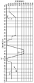
도 4에 대하여 아래에서 설명될 바와 같이, 전압 파형이 유사한 거동과 위상을 보일지라도 도 3에 도시된 파형(68)은 전류 파형이다. 도 3의 예시적인 실시예에서, 예를 들어, 배경 위상 및 피크 위상 동안에, 목표 전압이 유지되고 전류가 변화하여 원하는 레벨에서 전압을 유지시키는 폐루프 제어 방식이 수행된다. 중간 램프(ramp) 동안에, 폐루프 제어 방안은 전류와 전류 램프를 유지할 수 있다. 따라서 시스템은 전류와 전압 제어 사이에서 주기적으로 전이될 수 있어 원하는 파형을 실행한다.As will be described below with respect to FIG. 4, the
예로써, 도 3에 도시된 파형에서, 배경 위상(70) 동안, 원하는 배경 전압 레벨을 만족시키기 위하여 다시 변할 수 있을지라도, 약 25 내지 125 암페어(즉, 도 3에 도시된 바와 같이 약 115 암페어) 범위의 전류가 유지될 수 있다. 그후 피크 위상(72) 동안에, 약 250 내지 450 암페어(즉, 도 3에 도시된 바와 같이 약 400 암페어) 범위의 전류가 유지될 수 있고, 전압이 폐루프 제어된다면 다시 변할 수 있다. 다빙 위상(74) 동안에, 전류는 약 15 내지 25 암페어(즉, 도 3에 도시된 바와 같이 약 25 암페어) 범위일 수 있다. 에너지 전달, 전극 상에서의 용융된 볼의 형성, 볼의 이동 등을 허용하기 위하여 파형의 이들 위상 그리고 다른 위상의 지속 기간은 또한 프로그램될 수 있다. 특정 전압, 전류 그리고 실행된 기간은 사용된 전극 형태, 전극 치수, 와이어 공급 속도, 진행 속도 등과 같은 요소에 좌우될 수 있다.By way of example, in the waveform shown in FIG. 3, during the
다른 펄스식 용접 방안과는 대조적으로, 짧은 "다빙"에 기초하여 파형의 위상을 전달하기 위하여 용어 "피크", "다빙(dabbing)" 그리고 "배경"이 본 명세서에서 사용된다는 것이 주목될 수 있다. 본 기술 분야에 의하여 고려된 저-에너지 다빙을 실행하기 위하여 일반적인 시스템에서 이들 위상들이 프로그램되지 않을지라도 다른 프로그래밍 언어에서, 이 위상들은 "볼(ball)", "백(back)" 그리고 "선-단락(pre-short)"에 대응할 수 있다.It should be noted that, in contrast to other pulse welding schemes, the terms "peak "," dabbing ", and "background" are used herein to convey the phase of a waveform based on a short " . Although these phases are not programmed in a typical system to perform low-energy darbing as contemplated by the art, in other programming languages, these phases are referred to as "ball," "back," and " Quot; pre-short ".
도 4는 도 3에 도시된 형태의 프로그램에 기초한 다빙 펄스 파형의 다수의 사이클을 도시한다. 도 4에서, 전압 파형은 도면 부호 78에 의하여 지시되는 반면에, 전류 파형은 도면 부호 80에 의하여 지시된다. 전압 파형에서 보여질 수 있는 바와 같이, 각 사이클은 전압 배경 위상(82)을 포함하며, 전압 배경 위상 동안에 아크는 계속 진행하며 에너지는 전극과 용접 퍼들에 (그리고 주변 공작물에) 부가된다. 배경 위상에 피크 위상(84)이 후속하여, 그 배경 위상 동안에 생성된 용융된 금속이 피크 위상 동안에 용접 퍼들로 전달된다. 본 실시에서, 배경 위상과 피크 위상 모두는 폐루프 전압 제어되며, 아래에서 설명될 바와 같이, 대응하는 위상 동안에 전류의 변화를 야기한다. 용융된 금속이 용접 퍼들로 이동됨에 따라 도면 부호 86에 의하여 지시된 바와 같이, 전압의 신속한 강하는 짧은 단락 회로를 나타낸다. 이 위상은 대체로 빠르며, 이 시간 동안에 감소된 전류 목표를 사용함에 의하여 "과도한 단락(hard short)"이 방지될 수 있다.Fig. 4 shows a number of cycles of a falling pulse waveform based on the program of the type shown in Fig. In Figure 4, the voltage waveform is indicated by
대응하는 전류 파형(80) 상에서, 배경 위상은 도면 부호 88에 의하여 지시되는 반면에, 피크 위상은 도면 부호 90에 의하여 지시된다. 시스템이 목표 또는 프로그램된 전압을 유지하려고 시도함에 따라 이들 위상 동안에 전류는 변할 수 있다는 점을 유념해야할 것이다. 위에서 지적된 바와 같이, 그후 도면 부호 92에 의하여 지시된 바와 같이 감소된 다빙 전류 목표는 용융된 볼을 용접 퍼들 내에 용착하기 위하여 이용된다. 소정 사이클에서, 단락 회로를 클리어링하는 것을 돕기 위하여 "습윤(wet)" 위상(94)이 실행될 수 있다. 또한, 단락 회로가 쉽게 클리어되지 않는 사이클에서, 도면 부호 96에 의하여 지시된 바와 같이, 단락 회로를 강제적으로 클리어하기 위하여 더욱 상승된 전류가 이용될 수 있다.On the corresponding
도 3 및 도 4에 도시된 파형에서, 결과적인 "다빙" 방안은 일반적인 단락 회로 용접 파형과 다르다는 점을 유념해야 한다. 특히, 일반적인 용접 방안에서 후속의 배경 레벨보다 높은 레벨로 전류가 유지되는 "니(knee)" 위상이 피크 위상에 후속한다. 필요하다면, 니 위상은 단락 회로를 방지하는데 도움을 줄 수 있다. 필요하지 않다면, 니 위상은 기간이 감소될 수 있으며 그리고 파형은 배경 레벨로 더욱 빠르게 복귀될 수 있다.It should be noted that, in the waveforms shown in FIGS. 3 and 4, the resulting "falling wave" scheme is different from a typical short circuit welding waveform. In particular, a "knee" phase in which current is maintained at a higher level than the subsequent background level in a typical welding strategy follows the peak phase. If necessary, the knee phase can help prevent short circuits. If not required, the phase can be reduced in duration and the waveform can be returned to the background level more quickly.
한편, 본 기술에서, 피크 위상 직후에 배경 전류 레벨보다 작은 전류가 대상이 된다. 예를 들어, 배경 전류 레벨이 약 25 내지 125암페어일 수 있는 반면에, 다빙 전류는 약 25암페어보다 작을 수, 예를 들어 약 15 내지 25 암페어일 수 있다. 다빙 위상의 기간은 약 1 내지 5 밀리초와 같이 매우 짧을 수 있다. 이 감소된 전류는 단락 회로가 매우 적은 에너지로 용융 금속을 이동시키는 것을 허용하며 따라서 전극이 가열되는 것을 방지한다. 따라서 아크 길이는 재설정되며 그리고 아크의 과도한 돌출 및 넓어짐(flaring)이 방지된다.On the other hand, in the present technology, a current smaller than the background current level immediately after the peak phase is targeted. For example, the background current level may be about 25 to 125 amperes, while the falling current may be less than about 25 amperes, for example about 15 to 25 amperes. The duration of the doubling phase can be very short, such as about 1 to 5 milliseconds. This reduced current allows the short circuit to transfer the molten metal with very little energy and thus prevents the electrode from being heated. Thus, the arc length is reset and excessive projecting and flaring of the arc is prevented.
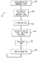
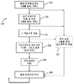
도 5는 다빙 방안을 실행하기 위한 예시적인 제어 로직을 도시한다. 도면 부호 98에 의하여 전체적으로 지시된 로직은 주기적이나, 도면 부호 100에 의하여 지시된 바와 같은 배경 위상(전류 실행에서 일정한 전압)을 유지하는 것으로 시작되는 것으로 고려될 수 있다. 이 위상 동안에, 아크가 형성되어 에너지는 전극과 용접 퍼들로 추가된다. 그후 도면 부호 102에 의하여 지시된 바와 같은, 피크 위상이 실행(전류 실행에서 다시 일정한 전압)된다. 이 위상은 대부분의 용융 금속의 분리가 이루어진다(즉, 높은 전류에 의하여 발생된 아크 힘으로 인하여 용융된 볼이 와이어의 단부에서 밀려 떨어진다), 그러나 이 위상 동안에 볼은 전체적으로 분리되진 않는다(그러나, 후미 테일에 의하여 부착된 상태로 남아 있다). 다빙 위상에서 뒤이은 단락 동안에 볼은 분리되지만, 볼이 이미 전극의 단부에서 떨어져 연장되어 있기 때문에 단락 회로를 제거하기 위하여 부가적인 에너지가 거의 또는 전혀 요구되지 않는다. 단계 104에서, 전류는 목표 최소값으로 감소되어 매우 낮은 에너지의 부가로 용융된 볼을 용접 퍼들 내로 다빙한다. 전류와 전압 레벨이 단락 회로가 지속되고 그리고 뒤이은 다빙 전류를 클리어하지 않았다는 것을 지시할 때와 같이, 필요하다면, 도면 부호 106에 의하여 지시된 바와 같이 단락 회로 루틴은 실행될 수 있다. 단계 108에서, 제어는 배경 레벨로 복귀하며 사이클은 반복될 수 있다.FIG. 5 illustrates exemplary control logic for executing the falling bank scheme. The logic indicated generally by
일부 실행에서 피크 위상에 뒤이은 저전류 목표에 의한 것보다는 다른 방식으로 다빙이 수행될 수 있다는 것이 주목되어야 한다. 예를 들어, 출력 단락 회로는 스위치를 통하여 생성될 수 있어 전극과 작업물 그리고 용접 퍼들 사이의 전류를 빠르게 감소시킨다. 유사하게, 아크를 소멸시키기 위하여 또는 적어도 에너지를 거의 또는 전혀 추가시키지 않기 위하여 피크 위상에 뒤이은 단기간 동안 출력 전력은 꺼질 수 있다.It should be noted that in some implementations it may be performed in a different manner than by a low current target followed by a peak phase. For example, an output short circuit can be generated through the switch to quickly reduce the current between the electrode, the workpiece, and the welding puddle. Similarly, the output power may be turned off for a short period of time following the peak phase to disarm the arc or at least add little or no energy.
도 3 및 도 4에 대하여 위에서 언급된 바와 같이, 피크 위상 직후에 (배경 전류 레벨보다 높은 전류 레벨에서의) 니 위상이 방지될 수 있다는 점에서 본 명세서에서 설명된 어떤 실시예는 일반적인 펄스 용접 파형과 다르다. 그러나, 또한 위에서 언급된 바와 같이, 하나 이상의 니 위상은 임의의 실시예에서 사용될 수 있다. 예를 들어, 도 6은 대체로 도 3에 도시된 파형과 유사하지만 피크 위상(72) 직후 그리고 다빙 위상(74) 직전의 하나 이상의 니 위상(112)을 포함하는 예시적인 파형(110)을 도시한다. 일반적으로, 하나 이상의 니 위상(112)이 피크 위상(72)을 뒤따르며, 그후 하나 이상의 배경 위상(70)이 뒤따르는 다빙 위상(74)으로 단락이 강제로 이루어진다. 도 6에는 단지 하나의 니 위상(112)과 단지 하나의 배경 위상(70)을 갖는 것으로 도시되어 있을지라도, 소정 실시예에서 하나 이상의 니 위상(112) 및/또는 하나 이상의 배경 위상(70)이 이용될 수 있는 것이 인식될 것이다. 일반적으로, 하나 이상의 니 위상(112)은 하나 이상의 배경 위상(70)보다는 크지만 피크 위상(72)보다는 작은 전류를 가질 것이다. 예를 들어, 도 6에 도시된 니 위상(112)은 약 125 암페어의 전류 레벨에 있는 반면에, 배경 위상(70)은 약 115 암페어의 전류 레벨에 있고 피크 위상(72)은 약 400 암페어의 전류 레벨에 있다. 다른 실시예에서, 전류 레벨이 하나 이상의 배경 위상(70)의 전류 레벨 이상을 유지하는 한 하나 이상의 니 위상(112)은 약 125 내지 250 암페어 범위의 전류 레벨을 가질 수 있다.As mentioned above with respect to Figures 3 and 4, some embodiments described herein in terms of being able to prevent knee phases (at current levels higher than the background current level) immediately after the peak phase, . However, as also noted above, one or more knee phases may be used in any embodiment. For example, FIG. 6 shows an
도 7은 도 6의 다빙 방안을 수행하기 위한 예시적인 컨트롤 로직을 도시한다. 전체적으로 도면 부호 114로 지시된 로직은 도 5에 도시된 로직(98)과 실질적으로 유사하나, 피크 위상(72)과 다빙 위상(74) 사이의 하나 이상의 니(knee) 위상(112)을 갖는 부가적인 단계(116)를 갖는다. 소정 실시예에서, 피크 위상(72), 니 위상(112) 또는 다빙 위상(74)은 전원 오프 신호로 교체될 수 있다. 특히, 전류 명령을 영(zero; 또는 약 1~2 암페어 또는 1 암페어보다도 작은 전류와 같은 매우 낮은 명령 레벨)으로 강하시킴에 의하여, 전력 공급 장치(10)를 구동하는 엔진을 비활성화시킴에 의하여 또는 전력 공급 장치(10)의 전원 게이트 신호를 턴 오프함에 의하여 전력 공급 장치(10)는 턴-오프될 수 있다. 전력 공급 장치(10)를 비활성화시킴에 의하여 도 7에 도시된 로직(114)의 피크 위상(72)과 관련된 단계 (예를 들어, 단계 102), 다빙 위상(74)과 관련된 단계(예를 들어, 단계 116) 또는 다빙 위상(74)과 관련된 단계(예를 들어, 단계 104) 중 어느 하나가 아크를 소멸시키는 단계로 대체될 수 있다. 예를 들어, 도 8은 대신에 전력 공급 장치(10)에 전력 오프 신호를 보내도록 이들 단계 중 어느 하나를 우회시키기 위한 예시적인 제어 로직(118)을 도시한다. 어떤 실시예에서, 아크가 소멸되면, 상대적으로 작은 전류(예를 들어, 약 1~2 암페어 또는 1 암페어보다도 낮은 전류)가 인가될 수 있어 전력 공급 장치(10)를 재활성화하고 아크를 재점화하며, 하나 이상의 배경 위상(70; 예를 들어 로직(118)의 단계(108)로의 복귀)이 그 뒤를 잇는다. 어떤 실시예에서, 아크가 점화되면, (정전 용량과 유도 용량으로 인하여 아크가 수 밀리초 동안 유지할 수 있기 때문에) 단락을 위하여 전압이 모니터링될 수 있으며, 그리고 아크가 소멸되면, 상대적으로 작은 전류(예를 들어, 약 1~2 암페어 또는 1 암페어보다도 낮은 전류)가 인가될 수 있어 전력 공급 장치(10)를 재활성화하고 아크를 재점화한다.FIG. 7 illustrates exemplary control logic for performing the falling-edge approach of FIG. The logic indicated generally by the
본 명세서 내에서 본 발명의 어떠한 특징만이 도시되고 설명된 반면에, 변형과 변화가 본 기술 분야의 지식을 가진 자에게 떠오를 것이다. 따라서, 첨부된 청구범위는 본 발명의 진정한 사상에 포함됨에 따라 이러한 변형과 변화 모두를 포함하도록 의도되었다는 것이 이해된다.While only certain features of the invention have been illustrated and described herein, variations and modifications will occur to those skilled in the art. It is, therefore, to be understood that the appended claims are intended to cover all such modifications and changes as fall within the true spirit of the invention.
Claims (20)
제어 파형에 기초하여 용접 전력 출력을 제공하도록 구성된 전력 변환 회로
를 포함하는 용접 시스템.A processing circuit configured to provide a control waveform comprising a peak phase, a dabbing phase immediately after the peak phase, and a backgroud phase subsequent to the falling phase; And
A power conversion circuit configured to provide a welding power output based on the control waveform;
≪ / RTI >
입력 전력을 제어 파형에 기초하여 용접 전력으로 변환시키는 것
을 포함하는 용접 방법.Generating a waveform for a welding power output comprising a peak phase, a falling phase immediately after the peak phase, and a background phase subsequent to the falling phase; And
Converting the input power into welding power based on the control waveform
≪ / RTI >
Applications Claiming Priority (4)
| Application Number | Priority Date | Filing Date | Title |
|---|---|---|---|
| US201261736393P | 2012-12-12 | 2012-12-12 | |
| US61/736,393 | 2012-12-12 | ||
| US14/076,705 | 2013-11-11 | ||
| US14/076,705 US10040143B2 (en) | 2012-12-12 | 2013-11-11 | Dabbing pulsed welding system and method |
Publications (1)
| Publication Number | Publication Date |
|---|---|
| KR20150086555A true KR20150086555A (en) | 2015-07-28 |
Family
ID=50879830
Family Applications (1)
| Application Number | Title | Priority Date | Filing Date |
|---|---|---|---|
| KR1020157018195A KR20150086555A (en) | 2012-12-12 | 2013-12-06 | Dabbing pulsed welding system and method |
Country Status (10)
| Country | Link |
|---|---|
| US (2) | US10040143B2 (en) |
| EP (1) | EP2931465B1 (en) |
| JP (1) | JP2015536829A (en) |
| KR (1) | KR20150086555A (en) |
| CN (1) | CN104837589B (en) |
| AU (1) | AU2013359847B2 (en) |
| BR (1) | BR112015008234A2 (en) |
| CA (1) | CA2885547C (en) |
| MX (1) | MX344686B (en) |
| WO (1) | WO2014093147A1 (en) |
Families Citing this family (34)
| Publication number | Priority date | Publication date | Assignee | Title |
|---|---|---|---|---|
| US10040143B2 (en) * | 2012-12-12 | 2018-08-07 | Illinois Tool Works Inc. | Dabbing pulsed welding system and method |
| US10906114B2 (en) | 2012-12-21 | 2021-02-02 | Illinois Tool Works Inc. | System for arc welding with enhanced metal deposition |
| US9950383B2 (en) | 2013-02-05 | 2018-04-24 | Illinois Tool Works Inc. | Welding wire preheating system and method |
| US10835983B2 (en) | 2013-03-14 | 2020-11-17 | Illinois Tool Works Inc. | Electrode negative pulse welding system and method |
| US11045891B2 (en) | 2013-06-13 | 2021-06-29 | Illinois Tool Works Inc. | Systems and methods for anomalous cathode event control |
| US10828728B2 (en) | 2013-09-26 | 2020-11-10 | Illinois Tool Works Inc. | Hotwire deposition material processing system and method |
| JP6387513B2 (en) * | 2014-02-25 | 2018-09-12 | パナソニックIpマネジメント株式会社 | Arc welding control method and arc welding apparatus |
| US11154946B2 (en) | 2014-06-30 | 2021-10-26 | Illinois Tool Works Inc. | Systems and methods for the control of welding parameters |
| US11198189B2 (en) | 2014-09-17 | 2021-12-14 | Illinois Tool Works Inc. | Electrode negative pulse welding system and method |
| US11478870B2 (en) * | 2014-11-26 | 2022-10-25 | Illinois Tool Works Inc. | Dabbing pulsed welding system and method |
| US10189106B2 (en) | 2014-12-11 | 2019-01-29 | Illinois Tool Works Inc. | Reduced energy welding system and method |
| US11370050B2 (en) | 2015-03-31 | 2022-06-28 | Illinois Tool Works Inc. | Controlled short circuit welding system and method |
| US11285559B2 (en) | 2015-11-30 | 2022-03-29 | Illinois Tool Works Inc. | Welding system and method for shielded welding wires |
| US10610946B2 (en) | 2015-12-07 | 2020-04-07 | Illinois Tool Works, Inc. | Systems and methods for automated root pass welding |
| US10675699B2 (en) | 2015-12-10 | 2020-06-09 | Illinois Tool Works Inc. | Systems, methods, and apparatus to preheat welding wire |
| US10695856B2 (en) * | 2016-10-07 | 2020-06-30 | Illinois Tool Works Inc. | System and method for short arc welding |
| CN106925865B (en) * | 2017-02-20 | 2018-10-23 | 上海威特力焊接设备制造股份有限公司 | A kind of gas shielded arc welding receipts arc device and method |
| CN106735735B (en) * | 2017-02-20 | 2018-10-23 | 上海威特力焊接设备制造股份有限公司 | A kind of pulse gas-shielded weldering receipts arc device and method |
| US10500671B2 (en) | 2017-04-06 | 2019-12-10 | Lincoln Global, Inc. | System and method for arc welding and wire manipulation control |
| US10766092B2 (en) | 2017-04-18 | 2020-09-08 | Illinois Tool Works Inc. | Systems, methods, and apparatus to provide preheat voltage feedback loss protection |
| US10870164B2 (en) | 2017-05-16 | 2020-12-22 | Illinois Tool Works Inc. | Systems, methods, and apparatus to preheat welding wire |
| WO2018227196A1 (en) | 2017-06-09 | 2018-12-13 | Illinois Tool Works Inc. | Welding torch, with two contact tips and a plurality of liquid cooling assemblies for conducting currents to the contact tips |
| CA3066619C (en) | 2017-06-09 | 2022-07-19 | Illinois Tool Works Inc. | Welding torch with a first contact tip to preheat welding wire and a second contact tip |
| US11590598B2 (en) | 2017-06-09 | 2023-02-28 | Illinois Tool Works Inc. | Systems, methods, and apparatus to preheat welding wire |
| CA3066677C (en) | 2017-06-09 | 2023-04-04 | Illinois Tool Works Inc. | Welding assembly for a welding torch, with two contact tips and a cooling body to cool and conduct current |
| US11524354B2 (en) | 2017-06-09 | 2022-12-13 | Illinois Tool Works Inc. | Systems, methods, and apparatus to control weld current in a preheating system |
| US11020813B2 (en) | 2017-09-13 | 2021-06-01 | Illinois Tool Works Inc. | Systems, methods, and apparatus to reduce cast in a welding wire |
| EP3843933A1 (en) | 2018-08-31 | 2021-07-07 | Illinois Tool Works, Inc. | Submerged arc welding systems and submerged arc welding torches to resistively preheat electrode wire |
| US11014185B2 (en) | 2018-09-27 | 2021-05-25 | Illinois Tool Works Inc. | Systems, methods, and apparatus for control of wire preheating in welding-type systems |
| US11504789B2 (en) * | 2018-10-19 | 2022-11-22 | Illinois Tool Works Inc. | Systems and methods to control pulse welding |
| US20200130087A1 (en) * | 2018-10-30 | 2020-04-30 | Lincoln Global, Inc. | Two-stage pulse ramp |
| CA3119590A1 (en) | 2018-12-19 | 2020-06-25 | Illinois Tool Works Inc. | Contact tip, wire preheating assembly, contact tip assembly and consumable electrode-fed welding type system |
| US20200246902A1 (en) * | 2019-01-31 | 2020-08-06 | Illinois Tool Works Inc. | Systems and methods for controlled arc and short phase time adjustment |
| US11772182B2 (en) | 2019-12-20 | 2023-10-03 | Illinois Tool Works Inc. | Systems and methods for gas control during welding wire pretreatments |
Family Cites Families (198)
| Publication number | Priority date | Publication date | Assignee | Title |
|---|---|---|---|---|
| US2365958A (en) | 1943-07-10 | 1944-12-26 | Electric Arc Inc | Continuous arc welding system |
| US2416047A (en) | 1943-07-10 | 1947-02-18 | George A Dolan | Combined reactor and induction preheater for use in electrode arc welding |
| US3288982A (en) | 1964-03-14 | 1966-11-29 | Suzuki Haruyoshi | High speed arc welding method |
| FR1443701A (en) | 1965-08-06 | 1966-06-24 | British Oxygen Co Ltd | Electric Arc Welding Improvements |
| US4188419A (en) | 1971-02-12 | 1980-02-12 | Licentia Patent-Verwaltungs-G.M.B.H. | Method for preventing cracks below seams during plating and welding |
| US3946349A (en) | 1971-05-03 | 1976-03-23 | The United States Of America As Represented By The Secretary Of The Air Force | High-power, low-loss high-frequency electrical coil |
| US3725629A (en) | 1971-07-16 | 1973-04-03 | Park O Ind Inc | Slab heating device |
| US3809853A (en) | 1972-08-24 | 1974-05-07 | Union Carbide Corp | Method for short circuit metal transfer arc welding |
| US3849871A (en) | 1973-08-06 | 1974-11-26 | Neander H | Method for welding pipes |
| DE2501928A1 (en) | 1975-01-18 | 1976-07-22 | Maschf Augsburg Nuernberg Ag | Preventing high short circuit currents when striking an arc - for the metal inert-gas welding of aluminium |
| GB1580443A (en) | 1976-08-21 | 1980-12-03 | Lucas Industries Ltd | Electrical coil assembly |
| ZA793101B (en) | 1978-07-05 | 1980-04-30 | Lucas Industries Ltd | Electrical coil assembly |
| SU872102A1 (en) | 1979-11-20 | 1981-10-15 | Уфимский авиационный институт им.С.Орджоникидзе | Arc-length stabilization method |
| DE3021659C2 (en) | 1980-06-10 | 1985-01-17 | M.A.N. Maschinenfabrik Augsburg-Nürnberg AG, 4200 Oberhausen | Process for measuring and controlling the feed rate of automatic welding machines |
| JPS5719166A (en) | 1980-07-08 | 1982-02-01 | Mitsubishi Electric Corp | Pulse arc welding device |
| JPS57109573A (en) | 1980-12-27 | 1982-07-08 | Mitsubishi Electric Corp | Pulse arc welding method |
| US4447703A (en) | 1981-11-13 | 1984-05-08 | Westinghouse Electric Corp. | Method and apparatus for arc welding |
| US4536634A (en) | 1982-01-08 | 1985-08-20 | Mitsubishi Denki Kabushiki Kaisha | Hot wire arc welding torch assembly |
| JPS58107274U (en) | 1982-01-08 | 1983-07-21 | 三菱電機株式会社 | Hot wire type arc welding torch |
| US4531040A (en) | 1982-01-11 | 1985-07-23 | Mitsubishi Denki K.K. | Hot wire type arc welding torch and cable |
| US4546234A (en) | 1983-08-11 | 1985-10-08 | Kabushiki Kaisha Kobe Seiko Sho | Output control of short circuit welding power source |
| JPH0679781B2 (en) | 1984-07-02 | 1994-10-12 | バブコツク日立株式会社 | Hot wire TIG welding equipment |
| JPS60108175A (en) | 1983-11-18 | 1985-06-13 | Osaka Denki Kk | Arc starting method in consumable electrode type arc welding method |
| JPS60108176A (en) | 1983-11-18 | 1985-06-13 | Osaka Denki Kk | Arc starting method in consumable electrode type arc welding method |
| CN86101294B (en) | 1985-02-13 | 1988-11-23 | 巴布考克日立株式会社 | Tungsten arc semiautomatic welding apparatus with inert atmosphere |
| US4631385A (en) | 1985-03-29 | 1986-12-23 | Dimetrics, Inc. | Automated position detectors and welding system utilizing same |
| US4604510A (en) | 1985-05-20 | 1986-08-05 | Tocco, Inc. | Method and apparatus for heat treating camshafts |
| US4580026A (en) | 1985-06-05 | 1986-04-01 | Westinghouse Electric Corp. | Method and apparatus for controlling the temperature of continuously fed wires |
| US4667083A (en) | 1986-02-14 | 1987-05-19 | Westinghouse Electric Corp. | Torch for preheating a continuously fed welding wire |
| US4954691A (en) * | 1986-12-10 | 1990-09-04 | The Lincoln Electric Company | Method and device for controlling a short circuiting type welding system |
| US4897523A (en) | 1986-12-11 | 1990-01-30 | The Lincoln Electric Company | Apparatus and method of short circuiting arc welding |
| US5148001A (en) | 1986-12-11 | 1992-09-15 | The Lincoln Electric Company | System and method of short circuiting arc welding |
| US5001326A (en) | 1986-12-11 | 1991-03-19 | The Lincoln Electric Company | Apparatus and method of controlling a welding cycle |
| JPS6471575A (en) | 1987-09-10 | 1989-03-16 | Matsushita Electric Ind Co Ltd | Method for restraining and controlling over welding current |
| JPH07115183B2 (en) | 1988-06-29 | 1995-12-13 | 三菱電機株式会社 | Load voltage detection system, pulse arc welding apparatus, pulse laser apparatus and surface treatment apparatus using the detection system |
| US4950348A (en) | 1988-10-13 | 1990-08-21 | Elva Induksjon A/S | Method for joining structural elements by heating of a binder |
| GB8900738D0 (en) | 1989-01-13 | 1989-03-08 | Central Electr Generat Board | Welding method and apparatus |
| SE8900758A0 (en) | 1989-03-06 | 1990-09-07 | Esab Ab | Turn on the pulse arc welding |
| US4973821A (en) | 1989-04-03 | 1990-11-27 | Donald L. Martin | Control unit for welding apparatus having offset and tracking control features |
| NO179483C (en) | 1989-08-29 | 1996-10-16 | Sumitomo Metal Ind | Process for establishing diffusion bonding between corrosion resistant materials |
| JP2935434B2 (en) | 1990-03-30 | 1999-08-16 | 日立ビアメカニクス株式会社 | Method and apparatus for controlling TIG welding power supply |
| US5140123A (en) | 1990-05-25 | 1992-08-18 | Kusakabe Electric & Machinery Co., Ltd. | Continuous manufacturing method for a metal welded tube and a manufacturing apparatus therefor |
| FR2663490B1 (en) | 1990-06-15 | 1992-09-11 | Rotelec Sa | INDUCTIVE HEATING COIL. |
| US5101086A (en) | 1990-10-25 | 1992-03-31 | Hydro-Quebec | Electromagnetic inductor with ferrite core for heating electrically conducting material |
| US5352871A (en) | 1991-02-20 | 1994-10-04 | Metcal Inc | System and method for joining plastic materials |
| US5270516A (en) | 1991-04-01 | 1993-12-14 | Matsushita Electric Industrial Co., Ltd. | Arc welding machine |
| DE4121237C2 (en) | 1991-06-27 | 1994-07-21 | Utp Schweissmaterial | Electronic welding current generator for pulsed arc welding |
| US5343023A (en) | 1991-08-23 | 1994-08-30 | Miller Electric Mfg. Co. | Induction heater having a power inverter and a variable frequency output inverter |
| DE4141927C2 (en) | 1991-12-19 | 1995-06-14 | Mtu Maintenance Gmbh | Method and device for welding workpieces |
| US5315089A (en) | 1992-03-02 | 1994-05-24 | Westinghouse Electric Corporation | System and method for converting an AGTAW welder into an AGMAW welder |
| US5412184A (en) | 1992-04-16 | 1995-05-02 | Gas Research Institute | Industion heating tool |
| US5349156A (en) | 1992-06-01 | 1994-09-20 | The United States Of America As Represented By The Secretary Of Commerce | Sensing of gas metal arc welding process characteristics for welding process control |
| US5278390A (en) | 1993-03-18 | 1994-01-11 | The Lincoln Electric Company | System and method for controlling a welding process for an arc welder |
| JP3209821B2 (en) | 1993-03-31 | 2001-09-17 | 日立ビアメカニクス株式会社 | Power control method of consumable electrode type gas shielded arc welding and welding device therefor |
| US5367138A (en) | 1993-06-28 | 1994-11-22 | Automation International Incorporated | Welding assurance control techniques |
| US5466916A (en) | 1993-09-24 | 1995-11-14 | Hidec Co., Ltd. | Method and apparatus for joint resin pipes using high-frequency electric induction heating |
| CN2181354Y (en) | 1993-11-17 | 1994-11-02 | 牟青岳 | Network voltage compensator for electric welder |
| JP3221203B2 (en) | 1994-01-13 | 2001-10-22 | 株式会社ダイヘン | Consumable electrode arc welding control method and power supply device |
| US5461215A (en) | 1994-03-17 | 1995-10-24 | Massachusetts Institute Of Technology | Fluid cooled litz coil inductive heater and connector therefor |
| DE69515083T2 (en) | 1994-05-27 | 2000-10-12 | Toshiba Kawasaki Kk | Control system for resistance welding machine |
| US5710413A (en) | 1995-03-29 | 1998-01-20 | Minnesota Mining And Manufacturing Company | H-field electromagnetic heating system for fusion bonding |
| US5708253A (en) | 1995-06-07 | 1998-01-13 | Hill Technical Services, Inc. | Apparatus and method for computerized interactive control, measurement and documentation of arc welding |
| US5714738A (en) | 1995-07-10 | 1998-02-03 | Watlow Electric Manufacturing Co. | Apparatus and methods of making and using heater apparatus for heating an object having two-dimensional or three-dimensional curvature |
| US5783799A (en) | 1996-01-11 | 1998-07-21 | Illinois Tool Works Inc. | Series resonant converter, and method and apparatus for control thereof |
| US5773799A (en) | 1996-04-01 | 1998-06-30 | Gas Research Institute | High-frequency induction heating power supply |
| BR9701473A (en) | 1996-04-22 | 1998-09-08 | Illinois Tool Works | System and method for inductive heating of a workpiece and system for continuous segmented inductive heating of a workpiece |
| US5742029A (en) | 1996-07-15 | 1998-04-21 | The Lincoln Electric Company | Method of welding wallpaper alloy an arc welder modified to practice same |
| US5739506A (en) | 1996-08-20 | 1998-04-14 | Ajax Magnethermic Corporation | Coil position adjustment system in induction heating assembly for metal strip |
| US5968587A (en) | 1996-11-13 | 1999-10-19 | Applied Materials, Inc. | Systems and methods for controlling the temperature of a vapor deposition apparatus |
| US5756967A (en) | 1997-04-09 | 1998-05-26 | The United States Of America As Represented By The Secretary Of Commerce | Sensing ARC welding process characteristics for welding process control |
| US5963022A (en) | 1997-06-05 | 1999-10-05 | Square D Company | Method and apparatus for compensating phase distortion caused by a high impedance voltage source |
| JPH11156542A (en) | 1997-11-28 | 1999-06-15 | Daihen Corp | Cable voltage lowering compensation method for stud welding |
| US6051810A (en) | 1998-01-09 | 2000-04-18 | Lincoln Global, Inc. | Short circuit welder |
| US6087626A (en) | 1998-02-17 | 2000-07-11 | Illinois Tool Works Inc. | Method and apparatus for welding |
| US6090067A (en) | 1998-02-19 | 2000-07-18 | Carter; Bruce C. | Surface access hemostatic valve |
| DE19808383A1 (en) | 1998-02-27 | 1999-09-02 | Volkswagen Ag | Method for MIG/MAG electric arc welding to join two or more components made of light metals or alloys |
| US6008470A (en) | 1998-03-26 | 1999-12-28 | University Of Kentucky Research Foundation | Method and system for gas metal arc welding |
| US6002104A (en) | 1998-04-17 | 1999-12-14 | Lincoln Global, Inc. | Electric arc welder and controller therefor |
| US6115273A (en) | 1998-07-09 | 2000-09-05 | Illinois Tool Works Inc. | Power converter with low loss switching |
| WO2000025185A1 (en) | 1998-10-27 | 2000-05-04 | Irobotics, Inc. | Robotic process planning using templates |
| US6906284B2 (en) | 1998-12-24 | 2005-06-14 | You-Chul Kim | Arc welding method |
| US6204476B1 (en) | 1999-05-12 | 2001-03-20 | Illinois Tool Works | Welding power supply for pulsed spray welding |
| AT409833B (en) | 1999-06-04 | 2002-11-25 | Fronius Schweissmasch Prod | METHOD FOR DETERMINING THE WELDING PROCESS VOLTAGE |
| US6169263B1 (en) | 1999-08-02 | 2001-01-02 | Automation International Inc. | Techniques for adaptive control of force in resistance welding applications |
| AT409601B (en) | 1999-11-02 | 2002-09-25 | Fronius Schweissmasch Prod | METHOD FOR TRANSMITTING DATA AND / OR SYNCHRONIZING BETWEEN AT LEAST TWO WELDING DEVICES AND THE DEVICE THEREFOR |
| US6560513B2 (en) | 1999-11-19 | 2003-05-06 | Fanuc Robotics North America | Robotic system with teach pendant |
| US6331694B1 (en) | 1999-12-08 | 2001-12-18 | Lincoln Global, Inc. | Fuel cell operated welder |
| AT412388B (en) | 2000-01-20 | 2005-02-25 | Fronius Schweissmasch Prod | METHOD FOR REGULATING A WELDING CURRENT SOURCE WITH A RESONANCE CIRCUIT |
| AUPQ528400A0 (en) | 2000-01-27 | 2000-02-17 | Crc For Welded Structures Limited | A welding control system |
| US6265688B1 (en) | 2000-02-03 | 2001-07-24 | Norman A. Lyshkow | Method of welding metals and apparatus for use therefor |
| US6278074B1 (en) | 2000-02-28 | 2001-08-21 | Lincoln Global, Inc. | Method and system for welding railroad rails |
| US6248976B1 (en) | 2000-03-14 | 2001-06-19 | Lincoln Global, Inc. | Method of controlling arc welding processes and welder using same |
| JP2001276971A (en) | 2000-03-29 | 2001-10-09 | Hitachi Ltd | Controlling method and apparatus for high frequency pulse welding machine |
| US7123990B2 (en) | 2000-06-02 | 2006-10-17 | Holland L.P. | Gap welding process |
| US6479792B1 (en) | 2000-09-06 | 2002-11-12 | Illinois Tool Works Inc. | Welding machine, system and method therefor |
| JP4846898B2 (en) * | 2000-09-12 | 2011-12-28 | 株式会社ダイヘン | AC pulse arc welding control method and welding power source apparatus |
| WO2002043248A2 (en) | 2000-11-23 | 2002-05-30 | The Indian Institute Of Technology (Iitd) | Analog to digital converter |
| CA2395912C (en) | 2000-12-07 | 2009-01-20 | Honda Giken Kogyo Kabushiki Kaisha | Control method for arc welding process and arc welding apparatus |
| US6583386B1 (en) | 2000-12-14 | 2003-06-24 | Impact Engineering, Inc. | Method and system for weld monitoring and tracking |
| US6501049B2 (en) | 2001-01-23 | 2002-12-31 | Lincoln Global, Inc. | Short circuit arc welder and method of controlling same |
| US6624388B1 (en) | 2001-01-25 | 2003-09-23 | The Lincoln Electric Company | System and method providing distributed welding architecture |
| US6486439B1 (en) | 2001-01-25 | 2002-11-26 | Lincoln Global, Inc. | System and method providing automated welding information exchange and replacement part order generation |
| US6847956B2 (en) | 2001-02-06 | 2005-01-25 | General Electric Company | System and method for determining specific requirements from general requirements documents |
| US6359258B1 (en) | 2001-02-16 | 2002-03-19 | Lincoln Global, Inc. | Method of determining cable impedance |
| CA2345836A1 (en) | 2001-02-23 | 2002-08-27 | Tony Lee Arndt | Method and system for hot wire welding |
| US6515258B2 (en) | 2001-02-28 | 2003-02-04 | General Electric Company | Long reach welding torch and method for selecting torch shape |
| US6472634B1 (en) | 2001-04-17 | 2002-10-29 | Lincoln Global, Inc. | Electric arc welding system |
| US6515259B1 (en) | 2001-05-29 | 2003-02-04 | Lincoln Global, Inc. | Electric arc welder using high frequency pulses |
| DE10136992A1 (en) | 2001-07-23 | 2003-02-06 | Emhart Llc Newark | Short duration arc welding involves comparing unsmoothed measurement curve with tolerance curve generated from smoothed measurement curve to detect high frequency faults |
| US6747247B2 (en) | 2001-09-19 | 2004-06-08 | Illinois Tool Works Inc. | Welding-type power supply with a state-based controller |
| US6670579B2 (en) | 2001-09-19 | 2003-12-30 | Illinois Tool Works Inc. | Welding-type system with network and multiple level messaging between components |
| US6642482B2 (en) | 2001-09-19 | 2003-11-04 | Illinois Tool Works Inc. | Welding-type system with robot calibration |
| JP4263886B2 (en) | 2002-02-22 | 2009-05-13 | 株式会社ダイヘン | Arc length control method for pulse arc welding |
| US6984806B2 (en) | 2002-07-23 | 2006-01-10 | Illinois Tool Works Inc. | Method and apparatus for retracting and advancing a welding wire |
| US6969823B2 (en) | 2002-07-23 | 2005-11-29 | Illinois Tool Works Inc. | Method and apparatus for controlling a welding system |
| US6720529B2 (en) | 2002-09-05 | 2004-04-13 | Illinois Tool Works Inc. | Autothread control for a wire feeder of a welding system |
| JP4478378B2 (en) | 2002-09-26 | 2010-06-09 | 株式会社ダイヘン | Output control method for welding power supply |
| US6909067B2 (en) | 2002-10-09 | 2005-06-21 | Illinois Tool Works Inc. | Method and apparatus for welding with CV control |
| US6707001B1 (en) | 2002-10-11 | 2004-03-16 | Illinois Tool Works Inc. | Method and apparatus of voltage protection for a welding-type device |
| US6812504B2 (en) | 2003-02-10 | 2004-11-02 | Micron Technology, Inc. | TFT-based random access memory cells comprising thyristors |
| US6995338B2 (en) | 2003-03-31 | 2006-02-07 | Illinois Tool Works Inc. | Method and apparatus for short circuit welding |
| US6974932B2 (en) | 2003-03-31 | 2005-12-13 | Illinois Tool Works Inc. | Method and apparatus for welding |
| US6974931B2 (en) | 2003-05-07 | 2005-12-13 | Illinois Tool Works Inc. | Method and apparatus for pulse and short circuit arc welding |
| US6933466B2 (en) | 2003-05-08 | 2005-08-23 | Illinois Tool Works Inc. | Method and apparatus for arc welding with wire heat control |
| US20040238511A1 (en) | 2003-05-27 | 2004-12-02 | Matus Tim A. | Method and apparatus for initiating welding arc with aid of vaporized chemical |
| JP4334930B2 (en) | 2003-07-16 | 2009-09-30 | 株式会社ダイヘン | Arc length control method for pulse arc welding |
| JP4490088B2 (en) | 2003-09-12 | 2010-06-23 | 株式会社ダイヘン | Output control method of pulse arc welding and output control method of arc length fluctuation pulse arc welding |
| CN100344402C (en) | 2003-09-26 | 2007-10-24 | 清华大学 | Method and system for reducing splash in gas shielded welding of short-circuiting transfer |
| WO2005030421A1 (en) | 2003-09-26 | 2005-04-07 | Tsinghua University | Method and system for reducing spatter in short circuit transition procedure for gas-shielded welding |
| AT413801B (en) | 2003-09-29 | 2006-06-15 | Fronius Int Gmbh | WELDING SYSTEM, AND METHOD FOR ENERGY ENGAGEMENT IN A WELDING PROCESS |
| CN102009245A (en) | 2003-10-23 | 2011-04-13 | 弗罗纽斯国际有限公司 | Method for controlling a welding process and welding device for carrying out a welding process |
| CN1323792C (en) | 2004-01-17 | 2007-07-04 | 上海威特力焊接设备制造有限公司 | Welding machine output characteristic control method |
| US7109439B2 (en) | 2004-02-23 | 2006-09-19 | Lincoln Global, Inc. | Short circuit arc welder and method of controlling same |
| US8704135B2 (en) * | 2006-01-20 | 2014-04-22 | Lincoln Global, Inc. | Synergistic welding system |
| US9393635B2 (en) | 2004-06-04 | 2016-07-19 | Lincoln Global, Inc. | Adaptive GMAW short circuit frequency control and high deposition arc welding |
| US7304269B2 (en) | 2004-06-04 | 2007-12-04 | Lincoln Global, Inc. | Pulse welder and method of using same |
| JP2006000857A (en) | 2004-06-15 | 2006-01-05 | Daihen Corp | Pulse arc welding power supply |
| CN100398246C (en) | 2004-06-30 | 2008-07-02 | 上海锅炉厂有限公司 | Process and device for automatic argon arc welding and narrow gap burial arc welding for circular pipe header seam |
| JP4211740B2 (en) | 2005-01-26 | 2009-01-21 | パナソニック株式会社 | Arc blow countermeasure control method and consumable electrode type pulse arc welding apparatus |
| JP2006263757A (en) | 2005-03-23 | 2006-10-05 | Daihen Corp | Method for controlling arc length in pulse arc welding |
| JP3933193B2 (en) | 2005-04-14 | 2007-06-20 | 松下電器産業株式会社 | Consumable electrode arc welding machine |
| AT501995B1 (en) * | 2005-05-24 | 2009-07-15 | Fronius Int Gmbh | COLD METAL TRANSFER WELDING METHOD AND WELDING SYSTEM |
| US7244905B2 (en) | 2005-06-09 | 2007-07-17 | Daimlerchrysler Corporation | Method for estimating nugget diameter and weld parameters |
| US8431862B2 (en) | 2005-08-25 | 2013-04-30 | Lincoln Global, Inc. | Torch for electric arc welding system |
| US8952291B2 (en) | 2005-09-15 | 2015-02-10 | Lincoln Global, Inc. | System and method for controlling a hybrid welding process |
| JP5214859B2 (en) | 2005-11-07 | 2013-06-19 | 株式会社ダイヘン | Output control method for consumable electrode arc welding power supply |
| US8704131B2 (en) | 2006-03-31 | 2014-04-22 | Illinois Tool Works Inc. | Method and apparatus for pulse welding |
| US7683290B2 (en) | 2006-05-12 | 2010-03-23 | Lincoln Global, Inc. | Method and apparatus for characterizing a welding output circuit path |
| US8759716B2 (en) | 2006-05-19 | 2014-06-24 | Illinois Tool Works Inc. | Method and apparatus for welding with limited term software |
| AT504197B1 (en) | 2006-09-08 | 2010-01-15 | Fronius Int Gmbh | WELDING METHOD FOR CARRYING OUT A WELDING PROCESS |
| US20080264923A1 (en) | 2007-04-30 | 2008-10-30 | Illinois Tool Works Inc. | Welding system and method with improved waveform |
| US20100059493A1 (en) | 2007-05-31 | 2010-03-11 | Mcaninch Michael D | Induction heated, hot wire welding |
| JP2009072826A (en) | 2007-08-27 | 2009-04-09 | Daihen Corp | Control method for pulse arc welding |
| CN201098775Y (en) | 2007-09-13 | 2008-08-13 | 上海梅达焊接设备有限公司 | System for monitoring condition of welding device |
| JP4950819B2 (en) | 2007-09-21 | 2012-06-13 | 株式会社ダイヘン | AC consumable electrode short-circuit arc welding method |
| US9442481B2 (en) | 2008-01-09 | 2016-09-13 | Illinois Tool Works Inc. | Automatic weld arc monitoring system |
| US10086461B2 (en) | 2009-01-13 | 2018-10-02 | Lincoln Global, Inc. | Method and system to start and use combination filler wire feed and high intensity energy source for welding |
| JP5398280B2 (en) | 2009-01-21 | 2014-01-29 | 株式会社ダイヘン | Pulse arc welding method |
| JP5199910B2 (en) | 2009-02-12 | 2013-05-15 | 株式会社神戸製鋼所 | Welding control apparatus for consumable electrode type pulse arc welding, arc length control method thereof, and welding system equipped with the welding control apparatus |
| WO2010123035A1 (en) | 2009-04-22 | 2010-10-28 | 株式会社Ihi検査計測 | Method of hybrid welding and hybrid welding apparatus |
| US8546726B2 (en) | 2009-06-03 | 2013-10-01 | Illinois Tool Works Inc. | Systems and devices for determining weld cable inductance |
| US8455794B2 (en) | 2009-06-03 | 2013-06-04 | Illinois Tool Works Inc. | Welding power supply with digital control of duty cycle |
| US8367972B2 (en) | 2009-06-11 | 2013-02-05 | Illinois Tool Works Inc. | Systems and methods for diagnosing secondary weld errors |
| US8288686B2 (en) | 2009-06-11 | 2012-10-16 | Illinois Tool Works Inc. | Welding systems and methods for controlling a wire feeder via a spool gun connection |
| EP2286949A1 (en) | 2009-08-18 | 2011-02-23 | Desarrollo Gestión Industrial y del medio Ambiente, S.A. | Electronic system for optimizing energy transfer for welding equipments |
| JP2011088209A (en) | 2009-08-19 | 2011-05-06 | Daihen Corp | Carbon dioxide pulsed arc welding method |
| US8610031B2 (en) | 2009-11-11 | 2013-12-17 | Lincoln Global, Inc. | Method of arc welding root pass |
| US10239146B2 (en) | 2010-02-12 | 2019-03-26 | Illinois Tool Works Inc. | Method and apparatus for welding with short clearing prediction |
| US8237087B2 (en) | 2010-02-23 | 2012-08-07 | Illinois Tool Works Inc. | Welding system with torque motor wire drive |
| US8395085B2 (en) | 2010-02-23 | 2013-03-12 | Illinois Tool Works Inc. | Wire feed speed referenced variable frequency pulse welding system |
| JP5293882B2 (en) | 2010-03-18 | 2013-09-18 | パナソニック株式会社 | Arc welding equipment |
| JP5234042B2 (en) | 2010-04-07 | 2013-07-10 | 株式会社デンソー | Arc welding method and apparatus |
| BR112012030269B1 (en) | 2010-05-28 | 2019-07-02 | Esab Ab | SYSTEM FOR CONTROLING A WELDING CURRENT IN A CURRENT WIDE ARC WELDING APPARATUS, SHORT ARC WELDING SYSTEM, AND METHOD FOR CONTROLING A POWER SUPPLY ON A WELDING ARC CONTINUOUS CURRENT FOR SHORT BOW WELDING |
| CN101862886B (en) | 2010-06-10 | 2012-02-22 | 哈尔滨工业大学 | Hot wire consumable electrode gas protection welding method and realization device thereof |
| CN102596475B (en) | 2010-09-10 | 2014-08-13 | 松下电器产业株式会社 | Arc welding control method |
| KR20120027764A (en) | 2010-09-13 | 2012-03-22 | 현대중공업 주식회사 | Apparatus for arc welding |
| JP2012066288A (en) | 2010-09-24 | 2012-04-05 | Fanuc Ltd | Arc welding method reducing occurrence of spatter at time of arc start |
| US9415457B2 (en) | 2010-10-22 | 2016-08-16 | Lincoln Global, Inc. | Method to control an arc welding system to reduce spatter |
| US9162308B2 (en) * | 2010-10-22 | 2015-10-20 | Lincoln Global, Inc. | Apparatus and method for pulse welding with AC waveform |
| US20120248080A1 (en) | 2011-03-29 | 2012-10-04 | Illinois Tool Works Inc. | Welding electrode stickout monitoring and control |
| US9073138B2 (en) | 2011-05-16 | 2015-07-07 | Lincoln Global, Inc. | Dual-spectrum digital imaging welding helmet |
| EP2718052B1 (en) | 2011-05-26 | 2016-08-31 | Victor Equipment Company | System for and method of generating a weld during a start of a welding process by restricting output power |
| US9403231B2 (en) | 2011-11-09 | 2016-08-02 | Illinois Tool Works Inc. | Hybrid pulsed-short circuit welding regime |
| CN102554418A (en) | 2012-02-16 | 2012-07-11 | 山东大学 | Microbeam tungsten argon arc welding method for magnesium alloy thin-walled tube |
| US20130264323A1 (en) | 2012-04-05 | 2013-10-10 | Lincoln Global, Inc. | Process for surface tension transfer short ciruit welding |
| CN202824943U (en) | 2012-05-24 | 2013-03-27 | 浙江申元机电有限公司 | Electric welding machine control module |
| US20140021183A1 (en) | 2012-07-19 | 2014-01-23 | Lincoln Global Inc. | Method and system for gas metal arc welding and a contact tip used for the same |
| US10040143B2 (en) | 2012-12-12 | 2018-08-07 | Illinois Tool Works Inc. | Dabbing pulsed welding system and method |
| US10065260B2 (en) | 2013-01-03 | 2018-09-04 | Illinois Tool Works Inc. | System and method for controlling an arc welding process |
| US9950383B2 (en) | 2013-02-05 | 2018-04-24 | Illinois Tool Works Inc. | Welding wire preheating system and method |
| US9550248B2 (en) | 2013-03-07 | 2017-01-24 | Lincoln Global, Inc. | Electric arc welder using high frequency pulses and negative polarity |
| US9623505B2 (en) | 2013-03-13 | 2017-04-18 | Lincoln Global, Inc. | Method and system of welding with a power supply having a single welding mode |
| US10835983B2 (en) | 2013-03-14 | 2020-11-17 | Illinois Tool Works Inc. | Electrode negative pulse welding system and method |
| US10040142B2 (en) | 2013-03-15 | 2018-08-07 | Lincoln Global, Inc. | Variable polarity pulse with constant droplet size |
| US11045891B2 (en) | 2013-06-13 | 2021-06-29 | Illinois Tool Works Inc. | Systems and methods for anomalous cathode event control |
| US10828728B2 (en) | 2013-09-26 | 2020-11-10 | Illinois Tool Works Inc. | Hotwire deposition material processing system and method |
| US9643273B2 (en) | 2013-10-14 | 2017-05-09 | Hypertherm, Inc. | Systems and methods for configuring a cutting or welding delivery device |
| US9539662B2 (en) | 2013-10-30 | 2017-01-10 | Illinois Tool Works Inc. | Extraction of arc length from voltage and current feedback |
-
2013
- 2013-11-11 US US14/076,705 patent/US10040143B2/en active Active
- 2013-12-06 CN CN201380062731.2A patent/CN104837589B/en active Active
- 2013-12-06 EP EP13811719.7A patent/EP2931465B1/en active Active
- 2013-12-06 AU AU2013359847A patent/AU2013359847B2/en not_active Ceased
- 2013-12-06 MX MX2015003481A patent/MX344686B/en active IP Right Grant
- 2013-12-06 BR BR112015008234A patent/BR112015008234A2/en not_active IP Right Cessation
- 2013-12-06 CA CA2885547A patent/CA2885547C/en active Active
- 2013-12-06 WO PCT/US2013/073490 patent/WO2014093147A1/en active Application Filing
- 2013-12-06 JP JP2015547428A patent/JP2015536829A/en active Pending
- 2013-12-06 KR KR1020157018195A patent/KR20150086555A/en not_active Application Discontinuation
-
2018
- 2018-07-05 US US16/027,548 patent/US20180311754A1/en active Pending
Also Published As
| Publication number | Publication date |
|---|---|
| EP2931465B1 (en) | 2018-08-08 |
| BR112015008234A2 (en) | 2017-07-04 |
| US10040143B2 (en) | 2018-08-07 |
| CN104837589A (en) | 2015-08-12 |
| MX344686B (en) | 2017-01-04 |
| EP2931465A1 (en) | 2015-10-21 |
| CN104837589B (en) | 2017-12-08 |
| US20140158669A1 (en) | 2014-06-12 |
| JP2015536829A (en) | 2015-12-24 |
| AU2013359847B2 (en) | 2016-05-19 |
| US20180311754A1 (en) | 2018-11-01 |
| CA2885547C (en) | 2017-10-10 |
| CA2885547A1 (en) | 2014-06-19 |
| AU2013359847A1 (en) | 2015-04-16 |
| WO2014093147A1 (en) | 2014-06-19 |
| MX2015003481A (en) | 2015-06-22 |
Similar Documents
| Publication | Publication Date | Title |
|---|---|---|
| KR20150086555A (en) | Dabbing pulsed welding system and method | |
| EP3223991B1 (en) | Short circuit arc welding method | |
| US9987701B2 (en) | Hybrid pulsed-short circuit welding regime | |
| US11253940B2 (en) | Reduced energy welding system and method | |
| CN108377644B (en) | Controlled short circuit welding system and method | |
| CN108472757B (en) | Welding system and method for shielded welding wire | |
| CA3068228C (en) | Systems and methods for controlled arc and short phase time adjustment |
Legal Events
| Date | Code | Title | Description |
|---|---|---|---|
| E902 | Notification of reason for refusal | ||
| E902 | Notification of reason for refusal | ||
| E601 | Decision to refuse application |