KR20150065692A - Multiple function arrangement for electronic apparatus and method thereof - Google Patents
Multiple function arrangement for electronic apparatus and method thereof Download PDFInfo
- Publication number
- KR20150065692A KR20150065692A KR1020157008365A KR20157008365A KR20150065692A KR 20150065692 A KR20150065692 A KR 20150065692A KR 1020157008365 A KR1020157008365 A KR 1020157008365A KR 20157008365 A KR20157008365 A KR 20157008365A KR 20150065692 A KR20150065692 A KR 20150065692A
- Authority
- KR
- South Korea
- Prior art keywords
- function
- electromagnetic radiation
- time period
- indicator element
- providing
- Prior art date
Links
Images

Classifications
-
- G—PHYSICS
- G08—SIGNALLING
- G08C—TRANSMISSION SYSTEMS FOR MEASURED VALUES, CONTROL OR SIMILAR SIGNALS
- G08C17/00—Arrangements for transmitting signals characterised by the use of a wireless electrical link
- G08C17/02—Arrangements for transmitting signals characterised by the use of a wireless electrical link using a radio link
-
- H—ELECTRICITY
- H03—ELECTRONIC CIRCUITRY
- H03K—PULSE TECHNIQUE
- H03K17/00—Electronic switching or gating, i.e. not by contact-making and –breaking
- H03K17/94—Electronic switching or gating, i.e. not by contact-making and –breaking characterised by the way in which the control signals are generated
- H03K17/941—Electronic switching or gating, i.e. not by contact-making and –breaking characterised by the way in which the control signals are generated using an optical detector
-
- H—ELECTRICITY
- H03—ELECTRONIC CIRCUITRY
- H03K—PULSE TECHNIQUE
- H03K17/00—Electronic switching or gating, i.e. not by contact-making and –breaking
- H03K17/94—Electronic switching or gating, i.e. not by contact-making and –breaking characterised by the way in which the control signals are generated
- H03K17/96—Touch switches
- H03K17/9627—Optical touch switches
- H03K17/9631—Optical touch switches using a light source as part of the switch
-
- G—PHYSICS
- G01—MEASURING; TESTING
- G01S—RADIO DIRECTION-FINDING; RADIO NAVIGATION; DETERMINING DISTANCE OR VELOCITY BY USE OF RADIO WAVES; LOCATING OR PRESENCE-DETECTING BY USE OF THE REFLECTION OR RERADIATION OF RADIO WAVES; ANALOGOUS ARRANGEMENTS USING OTHER WAVES
- G01S7/00—Details of systems according to groups G01S13/00, G01S15/00, G01S17/00
- G01S7/02—Details of systems according to groups G01S13/00, G01S15/00, G01S17/00 of systems according to group G01S13/00
- G01S7/024—Details of systems according to groups G01S13/00, G01S15/00, G01S17/00 of systems according to group G01S13/00 using polarisation effects
- G01S7/026—Details of systems according to groups G01S13/00, G01S15/00, G01S17/00 of systems according to group G01S13/00 using polarisation effects involving the transmission of elliptically or circularly polarised waves
-
- G—PHYSICS
- G01—MEASURING; TESTING
- G01S—RADIO DIRECTION-FINDING; RADIO NAVIGATION; DETERMINING DISTANCE OR VELOCITY BY USE OF RADIO WAVES; LOCATING OR PRESENCE-DETECTING BY USE OF THE REFLECTION OR RERADIATION OF RADIO WAVES; ANALOGOUS ARRANGEMENTS USING OTHER WAVES
- G01S7/00—Details of systems according to groups G01S13/00, G01S15/00, G01S17/00
- G01S7/48—Details of systems according to groups G01S13/00, G01S15/00, G01S17/00 of systems according to group G01S17/00
- G01S7/497—Means for monitoring or calibrating
-
- G—PHYSICS
- G08—SIGNALLING
- G08C—TRANSMISSION SYSTEMS FOR MEASURED VALUES, CONTROL OR SIMILAR SIGNALS
- G08C2201/00—Transmission systems of control signals via wireless link
- G08C2201/30—User interface
-
- G—PHYSICS
- G08—SIGNALLING
- G08C—TRANSMISSION SYSTEMS FOR MEASURED VALUES, CONTROL OR SIMILAR SIGNALS
- G08C2201/00—Transmission systems of control signals via wireless link
- G08C2201/50—Receiving or transmitting feedback, e.g. replies, status updates, acknowledgements, from the controlled devices
-
- H—ELECTRICITY
- H03—ELECTRONIC CIRCUITRY
- H03K—PULSE TECHNIQUE
- H03K2217/00—Indexing scheme related to electronic switching or gating, i.e. not by contact-making or -breaking covered by H03K17/00
- H03K2217/94—Indexing scheme related to electronic switching or gating, i.e. not by contact-making or -breaking covered by H03K17/00 characterised by the way in which the control signal is generated
- H03K2217/96—Touch switches
- H03K2217/96042—Touch switches with illumination
Abstract
본 발명은 기능 표시, 원격 제어 명령 수신 및 터치 센서의 다기능을 제공하기 위한 디바이스 내의 소자의 재사용에 관한 것이다. 디바이스는 사용자에게 상기 디바이스의 동작 상태를 표시하는 제1 기능을 제공하는 표시기 소자(21)와, 원격 제어 디바이스(22)로부터 원격 제어 명령(200)을 수신하는 제2 기능을 제공하는 수신기 소자(20)와, 터치 센서의 제3 기능을 제공하기 위해 표시기 소자와 수신기 소자를 결합하기 위한 수단(32, 35, 36, 37)을 포함한다. 표시기 소자는 이어지는 제2 시간 주기(720) 동안 제1 기능을 제공하고, 수신기 소자는 제2 시간 주기(721) 동안 제2 기능을 제공하며, 제1 및 제2 시간 주기는 연속적으로 교대로 일어난다.The present invention relates to the display of functions, reception of remote control commands, and reuse of elements within the device to provide the versatility of the touch sensor. The device comprises an indicator element 21 for providing a user with a first function for indicating the operating state of the device and a receiver element for providing a second function for receiving a remote control command 200 from the remote control device 22 20, and means (32, 35, 36, 37) for coupling the indicator element and the receiver element to provide a third function of the touch sensor. The indicator element provides a first function during a subsequent second time period 720 and the receiver element provides a second function during a second time period 721, wherein the first and second time periods alternate sequentially .
Description
본 발명은 일반적으로 전자 디바이스용 사용자 인터페이스에 관한 것이며, 보다 더 구체적으로, 터치-감응 스위치의 상태 변경을 트리거하기 위한 터치 감지에 관한 것이다.FIELD OF THE INVENTION The present invention relates generally to user interfaces for electronic devices and, more particularly, to touch detection for triggering state changes in a touch-sensitive switch.
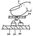
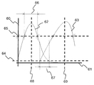
스위치 액츄에이터는 전통적으로 종래의 기계식 제어에 기초한다. 이러한 기계식 액츄에이터는 수분 응결 및 저온과 같은 불리한 환경 조건에 취약하다. 이들 기계식 스위치 액츄에이터 이외에도, 용량성 또는 광전자식 센서에 기초한 터치 스위치 액츄에이터가 사용된다. 이들은 새로운 하우징 설계 가능성, 간단한 제작, 낮은 조립 비용, 기계적 신뢰성, 및 다양한 환경적 조건 하에서의 동작의 편의를 제공한다. 용량성 터치 스위치 액츄에이터는 수용 표면(receptive surface) 또는 버튼의 존재를 요구하는데, 이는 스위치 액츄에이터를 수용하는 하우징의 설계 선택권을 감소시키며; 디바이스의 하우징을 설계할 때, 이들 용량성 스위치 버튼을 위한 배치가 예상되어야 한다. 이는, 동일한 장치의 다수의 변형에 대한 하우징을 설계할 때, 비용 감소를 어렵게 한다. 광전자식 센서에 기초한 스위칭 소자들은 증가된 설계 유연성을 허용하는데, 이는 이들이 반투명 표면, 예를 들어 디스플레이의 전면에 놓이는 표면 뒤에 배치될 수 있기 때문이다. 광전자식 스위치의 부재 또는 존재는 반투명 표면 상의 가시적 마킹(visible marking)의 부재 또는 존재에 의해 간단히 표시된다. 광전자식 센서에 기초한 스위칭 액츄에이터를 통해, 수동 및 능동 센서 간의 구별(distinction)이 이루어질 수 있다. 수동 센서에 있어서, 온도에 감응하는 광검출기 또는 방사 소자(radiating element)만이 사용되고, 능동 센서는 발광 소자(light emitter element) 및 감광성 수신기 소자를 포함한다. 발광 소자 및 감광성 수신기 소자에 따르면, 발광 소자는 광을 방출하고, 감광성 수신기 소자는, 오브젝트에 의한 반사 시 수신될 때, 발광 소자에 의해 방출된 광을 검출한다. 능동 센서는 변화하는 주변 광 조건에 독립적이라는 장점을 갖는다. 광전자식 센서는 접점없이 동작하는 근접 센서를 생성하는 것을 허용한다. 능동 광전자식 센서의 예시는 특허 문서 US2002/002080 A1 및 US2010/0060611 A1에서 발견될 수 있다. US2002/002080 A1에 기재된 광전자식 스위치의 예시는 도 1에 도시된다. 광전자식 스위치는 광 빔(86)을 방출하는 방출기 소자(81)를 포함하며, 오브젝트의 존재에 의해 반사되는 광 빔(86)을 검출하는 감광성 수신기 소자(82)를 더 포함한다. 방출기 소자(81) 및 수신기 소자(82)는 기판 상에 장착된다. 이 광전자식 스위치는 방출기 소자(81)에 의해 방출된 광을 통과시키도록 투명한 액츄에이팅 표면(84)을 포함한다. 액츄에이팅 표면(84)은, 손가락(F)과 같은 오브젝트로 터치되거나 또는 접근되는 경우, 방출기 소자(81)에 의해 방출된 광의 반사를 허용한다. 방출기(81)로부터의 광이 오브젝트에 의해 반사될 때, 이는 수신기 소자(82)에 의해 수신되는데, 수신기 소자(82)는 광을 전류로 변환한다. 연관된 전자 회로는 디바이스(81 및 82)를 사용하여 전자 스위치 기능을 제공하기 위한 어레인지먼트를 완성한다. US2010/00606011 A1은 터치-감응 LCD 디스플레이 내에서 터치 위치를 검출하기 위한 다수의 광 센서를 사용한 유사한 원리의 터치 디스플레이를 개시한다.Switch actuators are traditionally based on conventional mechanical controls. Such mechanical actuators are vulnerable to adverse environmental conditions such as moisture condensation and low temperature. In addition to these mechanical switch actuators, touch switch actuators based on capacitive or optoelectronic sensors are used. They provide new housing design possibilities, simple fabrication, low assembly cost, mechanical reliability, and ease of operation under a variety of environmental conditions. The capacitive touch switch actuator requires the presence of a receptive surface or button, which reduces the design choice of the housing housing the switch actuator; When designing the housing of the device, arrangements for these capacitive switch buttons should be expected. This makes cost reduction difficult when designing the housing for multiple variations of the same device. Switching devices based on optoelectronic sensors allow for increased design flexibility because they can be placed behind a translucent surface, for example, a surface that lies in front of the display. The absence or presence of optoelectronic switches is simply indicated by the absence or presence of visible marking on translucent surfaces. Through a switching actuator based on optoelectronic sensors, distinction can be made between passive and active sensors. In passive sensors, only temperature-sensitive photodetectors or radiating elements are used, and active sensors include light emitter elements and photosensitive receiver elements. According to the light emitting element and the photosensitive receiver element, the light emitting element emits light, and the photosensitive receiver element detects the light emitted by the light emitting element when it is received upon reflection by the object. The active sensor has the advantage of being independent of changing ambient light conditions. The optoelectronic sensor allows to create proximity sensors that operate without contacts. Examples of active optoelectronic sensors can be found in patent documents US2002 / 002080 A1 and US2010 / 0060611 A1. An example of the optoelectronic switch described in US2002 / 002080 A1 is shown in Fig. The optoelectronic switch includes an
하지만, 이들 종래 기술의 어레인지먼트는 여러 단점을 갖는다. 이들 단점 중 하나는 이들이 방출기 소자(81) 및 수신기 소자(82)와 같은 전용의 구성요소를 갖는 특수 어레인지먼트를 요구한다는 것이다. 또 다른 단점은, 이 요구된 특수 어레인지먼트가 디바이스의 동작 기능을 표시하는 발광 소자 및 원격 제어 명령의 수신을 위한 하나 이상의 추가적인 수신기 소자와 같은 다른 구성요소들을 위해 요구된 공간에 추가하여 차지되는, 광전자식 스위치를 구현하는 디바이스의 표면 상의 공간을 점유한다는 것이다.However, these prior art arrangements have several disadvantages. One of these disadvantages is that they require a special arrangement with a dedicated component such as
상업적 압력은 상이한 기능성을 갖는 유사한 버전의 동일 디바이스를 비용-효율적으로 생산하고 소수의 구성요소를 이용하여 보다 더 많은 기능을 제공할 능력을 개선시키도록 계속해서 압박하고 있다. 이에 따라, 종래 기술의 해법의 추가적인 최적화를 위한 필요가 있다.Commercial pressures continue to press to produce a similar version of the same device with different functionality cost-effectively and to improve the ability to provide more functionality using a few components. There is therefore a need for further optimization of prior art solutions.
본 발명은 종래 기술의 일부 애로점을 경감시키는 것을 목적으로 한다.The present invention aims to alleviate some of the drawbacks of the prior art.
이러한 목적으로, 본 발명은 디바이스를 포함하며, 디바이스는, 전자기 복사를 방출할 수 있으며, 사용자에게 디바이스의 기능의 동작 상태를 표시하는 제1 기능을 제공하기 위한 표시기 소자와; 원격 제어 디바이스로부터 비가시적 전자기 복사를 수신할 수 있으며, 원격 제어 명령을 수신하는 제2 기능을 제공하기 위한 수신기 소자;를 포함하며, 디바이스는 디바이스의 기능의 로컬 동작을 위한 터치 센서의 제3 기능을 제공하기 위해 표시기 소자와 수신기 소자를 결합하기 위한 수단을 더 포함하며, 오브젝트에 의한 반사를 통해 수신기 소자에 의해 제1 시간 주기 동안 수신될 때, 표시기 소자는, 디바이스의 동작 기능의 상태 변경을 트리거하는 전자기 복사의 패턴을, 제1 시간 주기 동안 방출하고, 표시기 소자는 이어지는(subsequent) 제2 시간 주기 동안 제1 기능을 제공하고, 수신기 소자는 제2 시간 주기 동안 제2 기능을 제공하며, 제1 및 제2 시간 주기는 반복적으로 교대로 일어난다.To this end, the invention comprises a device, the device comprising: an indicator element for emitting a first electromagnetic radiation and for providing a user with a first function for indicating the operating state of the function of the device; A receiver element for receiving an invisible electromagnetic radiation from a remote control device and for providing a second function for receiving a remote control command, the device comprising a third function of the touch sensor for local operation of the function of the device Further comprising means for combining the indicator element and the receiver element to provide a change in state of the operational function of the device when the indicator element is received for a first period of time by the receiver element through reflection by the object The indicator element emits a pattern of triggering electromagnetic radiation for a first time period, the indicator element provides a first function for a subsequent second time period, the receiver element provides a second function for a second time period, The first and second time periods are repeated alternately.
한 변형 실시예에 따르면, 표시기 소자는 적색 가시광 스펙트럼에서의 표시를 제공한다.According to one variant embodiment, the indicator element provides an indication in the red visible light spectrum.
한 변형 실시예에 따르면, 표시기 소자는 녹색 가시광 스펙트럼에서의 표시를 제공한다.According to one variant embodiment, the indicator element provides an indication in the green visible light spectrum.
한 변형 실시예에 따르면, 비가시적 전자기 복사는 적외선이다.According to one variant embodiment, the invisible electromagnetic radiation is infrared.
한 변형 실시예에 따르면, 제1 및 제2 시간 주기가 반복적으로 교대로 일어날 때, 인간 시각(human vision)의 지속성(persistence)으로 인해 동작 상태의 표시가 사용자에게 연속적이도록, 제1 시간 주기는 20 ms 미만이다. According to one variant embodiment, when the first and second time periods alternately occur repeatedly, the first time period is such that the display of the operating state is continuous to the user due to the persistence of the human vision Less than 20 ms.
한 변형 실시예에 따르면, 표시기 소자는 제2 시간 주기 동안 사용자에게 디바이스의 기능의 동작 상태를 표시하기 위해 전자기 복사를 방출한다.According to one variant embodiment, the indicator element emits an electromagnetic radiation to indicate to the user the operational status of the function of the device during a second period of time.
한 변형 실시예에 따르면, 표시기 소자는 제2 시간 주기 동안 사용자에게 디바이스의 기능의 동작 상태를 표시하기 위해 전자기 복사를 방출하지 않는다.According to one variant embodiment, the indicator element does not emit electromagnetic radiation to indicate to the user the operational status of the function of the device during the second time period.
한 변형 실시예에 따르면, 패턴은 원격 제어에 의해 사용된 주파수에서 변조된다.According to one variant embodiment, the pattern is modulated at the frequency used by the remote control.
한 변형 실시예에 따르면, 패턴은 펄스로 구성되며, 펄스 각각은 지속기간이 1 ms를 초과하지 않는 펄스 폭을 갖는다.According to one variant embodiment, the pattern consists of pulses, each pulse having a pulse width whose duration does not exceed 1 ms.
본 발명은 또한 디바이스의 기능의 동작을 위해 터치 센서 기능을 제공하기 위한 방법을 포함하며, 디바이스는 디바이스의 기능의 동작 상태를 사용자에게 표시하는 제1 기능을 위해 전자기 복사를 방출할 수 있는 표시기 소자와, 원격 제어 명령을 수신하는 제2 기능을 위해 원격 제어기로부터 비가시적 전자기 복사를 수신할 수 있는 수신기 소자를 포함하며, 본 방법은 표시기 소자 및 수신기 소자에 의해 제1 시간 주기 동안 제1 및 제2 기능을 제공하는 단계와; 표시기 소자 및 수신기 소자가 이어지는 제2 시간 주기 동안 터치 센서 기능을 제공하는 단계;를 포함하며, 제1 및 제2 시간 주기는 반복적으로 교대로 일어나고, 오브젝트에 의한 반사를 통해 수신기 소자에 의해 제1 시간 주기 동안 수신될 때, 표시기 소자는, 디바이스의 동작 기능의 상태 변경을 트리거하는 전자기 복사의 패턴을, 제1 시간 주기 동안 방출한다.The invention also encompasses a method for providing a touch sensor function for operation of a function of a device, the device comprising an indicator element capable of emitting an electromagnetic radiation for a first function of indicating to a user an operational state of the function of the device, And a receiver element capable of receiving an invisible electromagnetic radiation from a remote controller for a second function to receive a remote control command, the method comprising the steps of: 2 function; Providing a touch sensor function during a second time period followed by an indicator element and a receiver element, wherein the first and second time periods alternately occur repeatedly, When received over a period of time, the indicator element emits a pattern of electromagnetic radiation that triggers a state change of the operational function of the device during a first period of time.
본 발명의 방법의 한 변형에 따르면, 비가시적 전자기 복사는 적외선이다.According to one variant of the method of the invention, the invisible electromagnetic radiation is infrared.
본 발명의 방법의 한 변형에 따르면, 제1 및 제2 시간 주기가 반복적으로 교대로 일어날 때, 인간 시각의 지속성으로 인해 동작 상태의 표시가 사용자에게 연속적이도록, 제1 시간 주기는 20 ms 미만이다.According to a variant of the method of the invention, the first time period is less than 20 ms such that, when the first and second time periods alternately occur repeatedly, the indication of the operating state is continuous to the user due to the persistence of the human vision .
본 발명의 방법의 한 변형에 따르면, 표시기 소자는 제2 시간 주기 동안 사용자에게 디바이스의 기능의 동작 상태를 표시하기 위해 전자기 복사를 방출한다.According to one variant of the method of the invention, the indicator element emits an electromagnetic radiation to indicate to the user the operational status of the function of the device during a second period of time.
본 발명의 방법의 한 변형에 따르면, 표시기 소자는 제2 시간 주기 동안 사용자에게 디바이스의 기능의 동작 상태를 표시하기 위해 전자기 복사를 방출하지 않는다.According to one variant of the method of the present invention, the indicator element does not emit electromagnetic radiation to indicate to the user the operational status of the function of the device during the second time period.
본 발명의 방법의 한 변형에 따르면, 패턴은 원격 제어에 의해 사용된 주파수에서 변조된다.According to one variant of the method of the invention, the pattern is modulated at the frequency used by the remote control.
본 발명의 방법의 한 변형에 따르면, 패턴은 펄스로 구성되며, 펄스 각각은 지속기간이 1 ms를 초과하지 않는 펄스 폭을 갖는다.According to a variant of the method of the invention, the pattern consists of pulses, each pulse having a pulse width whose duration does not exceed 1 ms.
본 발명의 보다 더 많은 장점은 본 발명의 특정의 비-제한적인 실시예의 설명을 통해 나타날 것이다. 실시예들은 다음의 도면을 참조하여 설명될 것이다. Further advantages of the invention will emerge from the description of certain non-limiting embodiments of the invention. Embodiments will be described with reference to the following drawings.
본 발명에 개시된 기능 표시, 원격 제어 명령 수신 및 터치 센서의 다기능을 제공하기 위한 디바이스 내의 소자의 재사용을 통해 종래 기술의 단점을 극복할 수 있다. The disadvantages of the prior art can be overcome through the functional display, remote control command reception, and reuse of the devices in the device to provide the multifunction of the touch sensor disclosed in the present invention.
도 1은 본 문서의 배경 기술 섹션에서 앞서 이미 논의된 광전자식 스위치의 전형적인 종래 기술 어레인지먼트.
도 2는 추가적인 원격 제어 수신기 소자 및 전원 인가(power-on) 표시기를 포함하는 도 1에 도시된 전형적인 종래 기술 어레인지먼트.
도 3은 연관된 하드웨어 회로를 포함하는 도 2의 종래 기술 어레인지먼트의 블록도.
도 4는 본 발명에 따른 어레인지먼트의 비-제한적인 예시적 실시예를 도시하는 도면.
도 5는 도 4의 어레인지먼트에 따른 본 발명의 비-제한적인 실시예의 블록도.
도 6은 적외선 수신기 다이오드의 스펙트럼 분포와 중첩된 가시광을 방출하는 LED의 스펙트럼 분포.
도 7 및 도 8은 본 발명에 따른 신호의 시간적 분포의 비-제한적인 예시적 실시예. Figure 1 is a typical prior art arrangement of optoelectronic switches already discussed above in the background section of this document.
FIG. 2 is a typical prior art arrangement shown in FIG. 1, including an additional remote control receiver element and a power-on indicator. FIG.
Figure 3 is a block diagram of the prior art arrangement of Figure 2, including associated hardware circuitry;
Figure 4 illustrates a non-limiting exemplary embodiment of an arrangement according to the present invention.
Figure 5 is a block diagram of a non-limiting embodiment of the present invention in accordance with the arrangement of Figure 4;
6 shows the spectral distribution of the LEDs emitting visible light superimposed with the spectral distribution of the infrared receiver diodes.
Figures 7 and 8 are non-limiting exemplary embodiments of the temporal distribution of signals according to the present invention.
도 1은 본 문서의 배경 기술 섹션에서 앞서 이미 논의된 광전자식 스위치의 전형적인 종래 기술의 어레인지먼트이다. 다른 어레인지먼트들이 가능하며, 여기서 방출기 소자(81) 및 수신기 소자(82)는 기판(83) 상에 장착되지 않고, 액츄에이팅 표면(84)에 직접 고정된다. 소자(81 및 82)가 액츄에이팅 표면에 고정되어 액츄에이팅 표면과 평평한(level) 경우, 액츄에이팅 표면은 투명할 필요가 없다. 본 도면에서 손가락(F)은 액츄에이팅 표면을 터치하는 것으로서 도시된다. 실제로, 이는 방출기 소자(81)에 의해 방출되는 광의 반사에 의해 수신기 소자(82)에서 광을 검출하기 위해 표면에 접근하기에 충분할 수 있다. 터치 시에 스위치오버 상태(switchvoer state)가 검출되거나, 또는 접근이 어레인지먼트의 미세 동조 파라미터(fine tuning parameter)인 경우, 수신기 소자(82)에 의해 수신된 반사된 광의 진폭에 걸쳐 차이가 발생할 수 있다.Figure 1 is a typical prior art arrangement of optoelectronic switches already discussed above in the background section of this document. Other arrangements are possible in which the
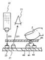
도 2는 추가적인 원격 제어 수신기 소자 및 전원 인가 표시기를 포함하는 도 1에 도시된 전형적인 종래 기술의 어레인지먼트이다. 이러한 어레인지먼트에서, 추가적인 원격 제어 수신기 소자(20)는 기판(83) 상에 장착된다. 원격 제어 수신기 소자(20)는 원격 제어기로부터 적외선 펄스를 검출하기 위해 원격 제어 디바이스(22)에 의해 방출된 적외선 스펙트럼 내의 광을 잘 수용하는데, 이는 사용자가, 어레인지먼트를 구현하는 디바이스로 명령을 원격 전송하는 것을 허용한다. 발광 다이오드(Light Emitting Diode) 또는 LED와 같은 추가적인 전원 인가 발광 디바이스(21)는 그 어레인지먼트가 대응하는 디바이스의 전원 인가 상태를 표시하며, 광은 사용자의 눈(23)에 의해 검출될 수 있다. 관찰될 수 있는 바와 같이, 이 어레인지먼트에는 두 개의 발광 소자(81 및 21)와 두 개의 수광 소자(82 및 20)가 존재한다. 이들 소자는:Figure 2 is an exemplary prior art arrangement shown in Figure 1 that includes additional remote control receiver elements and a power up indicator. In this arrangement, an additional remote
- 원격 제어 명령 수신, - Remote control command reception,
- 전원 인가 상태 표시, 및 - Power on status indication, and
- 광전자식 스위칭 또는 터치 감지 - Optoelectronic switching or touch sensing
의 기능을 제공하기 위해 필수적이다.It is essential to provide the function of.
이들 3가지의 기능 각각은 (도 3에 도시된) 전용의 연관된 전자 회로를 수반한다. 3가지 기능 각각은 개별적으로 구현된다. 어떤 시너지 효과도 존재하지 않으며, 이러한 해법은 최적화되지 않는다.Each of these three functions involves dedicated associated electronic circuitry (shown in FIG. 3). Each of the three functions is implemented separately. There is no synergy, and this solution is not optimized.
도 3은 종래 기술의 디바이스에서 발견될 수 있는 바와 같이, 연관된 회로를 포함하는 도 2의 종래 기술의 어레인지먼트의 블록도이다. 블록(300)은 터치 센서의 기능을 제공하도록 요구된 회로를 나타낸다. 블록(301)은 디바이스의 기능의 동작 상태의 가시적 표시를 사용자에게 제공하기 위한 표시기의 기능을 제공하도록 요구된 회로를 나타낸다. 블록(302)은 원격 제어 명령을 수신하는 기능을 제공하기 위해, 원격 제어 디바이스로부터 비가시적 전자기 복사를 수신할 수 있는 수신기 소자를 위해 필요한 회로를 나타낸다.Figure 3 is a block diagram of the prior art arrangement of Figure 2, including associated circuitry, as can be found in prior art devices.
블록(300)은 적외선 광원(81), 적외선 광원용 구동 회로(30), 적외선 센서(82), 자동 이득 제어(Automatic Gain Control)를 이용한 증폭기를 전형적으로 포함하며 적외선 센서로부터 신호를 수신하기 위한 구동 회로, 및 출력이 디바이스의 기능을 스위칭 온(ON)하거나 또는 스위칭 오프(OFF)하는 것을 허용하는 온/오프 상태 플립-플롭을 포함한다. 블록(301)은 방출기 소자(81) 및 구동 회로(33)를 포함한다. 블록(302)은 적외선(IR light) 센서(20), 구동 회로(34), 및 펄스 재성형기(35)를 포함한다. 펄스 재성형기는 구동기(34)로부터 수신된 원래의 펄스형(raw pulse forms)을 재성형하여, 펄스형은, 펄스형이 어떤 원격 제어 명령에 대응하는지를 결정하도록 해석될 준비가 된다.The
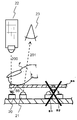
도 4는 본 발명에 따른 어레인지먼트의 비-제한적인 예시적 실시예이다. 여기서, 3가지의 기능 - 원격 제어 수신기, 전원 인가 표시기, 및 광전자식 스위치/터치 센서 - 은 두 개의 광전자식 소자: 적외선 수신기(20) 및 전원 인가 방출기(21)만을 사용함으로써 제공된다. 관찰될 수 있는 바와 같이, 빗장이 그어진 소자 - 적외선 송신기(81) 및 적외선 수신기(82) - 는 더 이상 필요가 없다. 전원 인가 표시기 소자(21) 및 적외선 원격 제어 수신기 소자(20)의 상대적 근접함으로 인해, 적외선 수신기 소자는 전원 인가 표시기 소자(21)에 의해 방출된 일부 광을 수신한다. 전원 인가 표시기 소자(21)는 가시적 파장 내의 광을 방출하도록 설계되며, 이는 또한 적외선 수신기 소자(20)에 의해 검출될 수 있는 파장 내의 저 진폭의 일부 ‘가짜(spurious)’ 광을 방출한다(도 6은 이러한 현상을 더 도시할 것이다). 적외선 수신기 소자(20)/전원 인가 표시기(21)의 전면에 있는 구역에 접근하는 사용자의 손가락(F)은 적외선 수신기 소자(20)에 의해 수신되는 전원 인가 표시기에 의해 방출된 ‘가짜(spurious)’ 적외선을 반사시킬 것이다. 가시광의 파장은 녹색 광에 대해 490 내지 540 ㎚의 분포, 주황색 광에 대해 600 내지 650 ㎚의 분포, 및 적색 광에 대해 650 내지 700 ㎚의 분포를 갖는다. 적외선은 가시광보다 더 긴 파장을 갖는데, 즉 780 내지 1060 ㎚이다. 원격 제어 디바이스를 위한 전형적인 적외선 파장은 대략 940 ㎚ 이다. 전형적인 적색 전원 인가 LED는 또한, 도 6에 따라 확인될 수 있는 전형적인 적외선 원격 제어 수신기 다이오드의 감도의 스펙트럼과 겹치는 일부 적외선을 방출한다. 적외선 수신기 소자(20) 및 전원 인가 표시기(21)는 이에 따라 광전자식 스위치의 기능을 제공하도록 사용될 수 있다. 하지만, 이들 소자가 이들의 본래의 기능들 - 원격 제어 명령 수신 및 전원 인가 상태 표시 - 을 계속 제공하기 위해, 특수 어레인지먼트가 필요하다. 이러한 특수 어레인지먼트는 도 5 및 도 6의 도움으로 논의된다.Figure 4 is a non-limiting illustrative embodiment of an arrangement according to the present invention. Here, three functions-a remote control receiver, a powered-on indicator, and an optoelectronic switch / touch sensor-are provided by using only two optoelectronic components: the
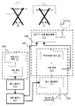
도 5는 도 4의 어레인지먼트에 따른 본 발명의 비-제한적인 실시예의 블록도이다.5 is a block diagram of a non-limiting embodiment of the present invention in accordance with the arrangement of FIG.
종래 기술의 도 3을 도 5와 비교하면, 소자들 및 회로들의 재사용으로 인해, 적외선(IR light) 광원(81), 구동 회로(30), 적외선(IR light) 센서(82), 및 구동 회로(31)가 더 이상 터치 센서의 제3 기능을 제공하도록 요구되지 않는다는 것이 관찰될 수 있다. 펄스 발생기(36)는 전자식 스위치 또는 터치 센서의 제3 기능을 제공하기 위해 적외선(IR light) 센서(20)에 의한 수신을 위해 정해진 펄스를 제공한다. 교류 발전기(alternator)(537)는, 원격 제어 명령을 수신하는 제2 기능을 제공하기 위해 적외선(IR light) 센서(20)의 출력을 펄스 재성형기(535)로 스위칭하거나, 또는 터치 센서의 제3 기능/광전자식 스위치 기능을 제공하기 위해 적외선(IR light) 센서(20)의 출력을 온/오프 상태의 플립 플롭(532)으로 스위칭한다. 교류 발전기는 펄스 발생기(536)로부터의 신호로 구동되는데, 이는 온/오프 상태 플립 플롭(532) 또는 펄스 재성형기(535)를 교대로 인에이블링한다.3 of the prior art and Fig. 5, due to the reuse of elements and circuits, an IR
도 6은 적외선 수신기 다이오드의 스펙트럼 분포와 중첩된 발광 LED의 스펙트럼 분포이다.Figure 6 is a spectral distribution of the infrared LED diodes and a spectral distribution of the superimposed luminescent LEDs.
60은 Y-축 또는 진폭을 나타낸다. 61은 X-축 또는 파장을 나타낸다. 62는 가시적 스펙트럼 내에서 방출하는 전형적인 LED의 스펙트럼 곡선을 나타낸다. 63은 전형적인 IR 수신기의 스펙트럼 수용성(spectral receptivity) 곡선을 나타낸다. 68은 곡선(62)의 중앙값(median)(예컨대, 675 ㎚)을 나타내고, 69는 곡선(63)의 중앙값(예컨대, 940 ㎚)을 나타낸다. 64는 IR 수신기를 사용하여 펄스된 적외선을 검출하기 위한 최소 검출 진폭을 나타낸다. 67은 LED에 의해 방출된 광이 IR 수신기에 의해 검출될 수 있는 구역을 나타낸다. 66은 데이터 시트에서 도시된 바와 같이 LED에 의해 방출된 광 스펙트럼의 전형적인 파장(전형적으로 20 ㎚)을 나타낸다.60 represents the Y-axis or amplitude. 61 denotes an X-axis or wavelength. 62 represents the spectral curve of a typical LED emitting within a visible spectrum. 63 represents the spectral receptivity curve of a typical IR receiver. 68 represents the median (for example, 675 nm) of the
LED 및 IR 수신기의 전형적인 데이터 시트에서, Y-축(60)은 선형 눈금(linear scale)으로 표현되는데, 이는 전자 설계 엔지니어의 주요 관심이 중앙값에 집중되기 때문이다. 이러한 선형 프리젠테이션을 사용하면, 발광의 진폭의 하단 부분은 상당히 수직인 선으로 표현된다. 하지만, 인간의 눈으로 검출될 수 없는 것으로 고려되는 {도 6에서 점선(65) 아래에 있는 것으로 도시되는) 저-진폭 구역에서, 곡선들이 겹친다. IR 수신기가 매우 높은 감도를 갖기 때문에, 이에 따라 IR 수신기가 구역(67)에서 LED에 의해 방출된 광을 검출하는 것이 가능하다. 놀랍게도, IR 수신기에 의해 검출될, 구역(67)에서 하강하는 LED에 의해 방출된 광의 저 진폭은 충분히 중요한데, 여기서 IR 수신기는 수 미터의 거리에 있는 원격 제어기로부터의 광을 수신하도록 설계되고; 이로써, IR 수신기는 이러한 저 진폭의 적외선(IR light)을 검출하기에 적합하다. 본 발명에서, 이들 특징은 유리하게 고려되고 활용된다.In a typical data sheet of an LED and IR receiver, the Y-
본 발명의 최적화에 따르면, 어레인지먼트의 감도는, IR 수신기의 이득을 제어하며 주변 광 또는 인공 광원의 존재로 인한 교란(perturbations)에 대항하여 IR 수신기의 이득을 보호하는 자동 이득 제어(AGC) 회로의 특성을 고려함으로써 최적화된다. 실제로, AGC 회로는 IR 원격 제어기로부터 짧은 적외선 펄스를 수신하도록 설계되는 IR 수신기가 적외선 ‘잡음(noise)’에 잘 견디게 한다. IR 원격 제어의 IR 송신기의 펄스는, AGC가 활성화된 채로 유지되어(전형적으로 1 ms) 상당한 이득을 제공하기에 충분히 짧다. 하지만, 전술된 ‘잡음’은 전형적으로 원격 제어기로부터 수신된 펄스보다 더 긴 지속시간을 갖는 특성이 있으며, 이에 따라 AGC는, 지속시간이 원격 제어기로부터의 IR 송신기로부터 예상된 펄스의 지속시간을 초과하는 경우, 이득을 감소시키도록 설계된다. AGC로 하여금 이득을 감소시키도록 하는 광 펄스의 지속시간은 본 명세서에서는 AGC 반응 지연(reaction delay)으로 지칭된다. 본 발명은, 각각의 펄스의 지속시간이 AGC 반응 지연을 초과하지 않는 광 펄스의 패턴을 제공함으로써, 이러한 AGC의 특성을 활용하여, 이득은 고 레벨로 유지된다.According to the optimization of the present invention, the sensitivity of the arrangement is controlled by an automatic gain control (AGC) circuit which controls the gain of the IR receiver and protects the IR receiver's gain against perturbations due to ambient light or the presence of an artificial light source. Are optimized by considering the characteristics. Indeed, the AGC circuitry allows an IR receiver designed to receive short infrared pulses from an IR remote controller to tolerate infrared 'noise'. The pulses of the IR remote control IR transmitter are kept short enough to keep the AGC active (typically 1 ms) and provide significant gain. However, the aforementioned " noise " is typically characterized by a longer duration than the pulses received from the remote controller, so that the AGC can not exceed the duration of the expected pulse from the IR transmitter from the remote controller , It is designed to reduce the gain. The duration of the optical pulse that causes the AGC to reduce the gain is referred to herein as the AGC reaction delay. The present invention utilizes the characteristics of this AGC so that the gain remains at a high level, by providing a pattern of optical pulses whose duration of each pulse does not exceed the AGC response delay.
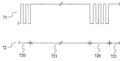
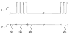
도 7 및 도 8은 본 발명에 따른 신호의 시간적 분포의 비-제한적인 예시적 실시예이다. 특히, 도 7은 본 발명에 따른 전원 인가 표시기(21)에 의한 광의 방출을 도시하며, 전원 인가 표시기(21)는 가시적 ‘온’ 상태를 표시한다. 도 8은, 전원 인가 표시기(21)가 가시적 ‘오프’ 상태를 표시할 때의 본 발명에 따른 전원 인가 표시기(21)에 의한 광의 방출을 도시한다. 도 7은, 본 발명에 따라, 전원 인가 표시기(21)가 계속적으로 온{주기(721)}이고, 재빨리 온 상태로부터 오프 상태로 스위칭{주기(720)}되는 주기들로 전원 인가 표시기(21)의 방출이 분할되는 것을 도시한다. 주기(721 및 720)의 분포는 주기(720)가 인간의 눈(23)으로 검출될 수 없게 충분히 짧도록 선택된다. 인간의 시각의 지속성을 고려하면, 주기(720)는 바람직하게는 20 ms 미만이다. 다른 말로, 동작 상태의 표시가 인간 시각의 지속성으로 인해 사용자에게 연속적이도록, 주기(720)는 20 ms 미만이며, 이는 제1 및 제2 주기가 반복적으로 교대로 일어난다는 것을 상기시킨다. 광 펄스가 손가락(F)과 같은 근접한 오브젝트에 의해 반사될 때, 주기(720)는 적외선 수신기(20)에 의해 검출되도록 정해지는 광 펄스를 전송하도록 사용된다. 손가락(F)과 같은 반사 오브젝트의 존재의 검출은, 사전 결정된 수의 펄스가 수신되는 경우에 검출된다. 본 발명은 전원 인가 표시기가 사용자에게 ‘오프’ 상태를 표시하도록 광(예를 들어, 적색 또는 주황색 광)을 방출할 때 사용될 수 있으면서, 본 발명은 또한 전원 인가 표시기(21)가 ‘오프’ 상태를 표시하도록 광을 방출하지 않을 때에도 사용될 수 있다. 주기(720)는 20 ms 미만이며, 동작 상태의 표시는 인간의 시각의 지속성으로 인해 사용자에게 연속적이다.Figures 7 and 8 are non-limiting exemplary embodiments of the temporal distribution of signals in accordance with the present invention. In particular, FIG. 7 shows the emission of light by the power-on
주기(721 또는 821) 동안, 적외선 수신기(20)는 적외선 원격 제어기(22)로부터의 명령을 검출하는 기능을 위해 사용된다. 이로써, 본 어레인지먼트는 버튼 동작의 검출에 대한 주기(720/820) 동안에 전원 인가 표시기(21)로부터 펄스를 검출하는 것과, 주기(721/821) 동안에 원격 제어기(22)로부터 펄스를 검출하는 것 사이에서, 적외선 수신기(20)를 교대로 사용한다. 이러한 교대는, 예를 들어 도 5의 교류 발전기(537)에 의해 동작된다. 원격 제어 명령의 검출을 위해, 이러한 교대는 전원 인가 표시기(21)로부터의 펄스의 수신과, 원격 제어기(22)로부터 수신된 펄스 사이에서 주기(720/820) 동안 간섭을 회피하며, 원격 제어 명령의 검출은 주기(720/820) 동안 디스에이블링된다. 원격 제어기로부터의 명령을 검출하는 것에 있어서의 이러한 짧은 중단은 원격 제어 명령의 수신에 해롭지 않은데, 그 이유는 원격 제어기 상에서의 전형적인 버튼 가압이 적어도 1초가 걸리며, 이는 대체로 주기(720/820)에 걸치게 되어, 원격 제어 펄스가, 후속하는 주기(721/821) 동안 수신될 것이기 때문이다. 추가적으로, 원격 제어 명령의 검출에 대해, 주기(721/821) 동안 전원 인가 표시기(21)로부터 펄스를 수신하는 것을 통해, 원격 제어기(22)의 펄스를 수신하는 것에 의한 간섭이 회피되는데, 이는 전원 인가 표시기(21)가 이들 주기 동안에 광 펄스를 방출하지 않기 때문이다.During the
광전자식 스위치에 의한 터치 감지에 대해, 펄스가 전원 인가 표시기(21)로부터 수신되는 경우, 적외선 수신기(20)는 그것이 손가락(F)에 의해 마스킹된 이후로 적외선 원격 제어기(22)로부터 어떤 펄스도 수신하지 않을 것이기 때문에, 본 어레인지먼트가 전원 인가 표시기(21)로부터 펄스를 수신할 여지가 있는 주기(720/820) 동안 원격 제어기(22)로부터 펄스를 수신하는 것에 의한 어떤 간섭도 있지 않을 것이다. 하지만, 만약, 그러한 경우, 원격 제어기(22) 및 전원 인가 표시기(21)로부터 수신된 펄스는 훼손될 것이며, 검출은 연관된 회로에 의해 쉽게 거부될 수 있다.For touch sensing by the optoelectronic switch, when a pulse is received from the power up
본 발명의 한 변형 실시예에 따르면, 논의된 광 펄스의 방출의 주파수는, 적외선 수신기(20)가 또한 원격 제어기(22)로부터 적외선 펄스를 수신하는 기능을 위해 사용될 때 원격 제어기에 의해 사용된 주파수(전형적으로, 33, 36 또는 38 kHz)에 대응하도록 선택된다. 이 변형 실시예는, 적외선 수신기(20)의 회로가 ‘잡음’, 즉 주변 광, 형광등, 플라즈마 또는 LCD 스크린과 같은 다른 광원으로부터의 임펄스를 거부하기 위해 원격 제어기(22)의 적외선 펄스 주파수에 대응하지 않는 주파수들의 펄스를 거부하도록 설계되기 때문에, 적외선 펄스의 수신을 위한 최대 감도를 획득하는 장점을 갖는다.According to one variant embodiment of the invention, the frequency of the emission of the discussed light pulse is such that the frequency used by the remote controller when the
또 다른 변형 실시예에 따르면, 본 발명은, 오직 광 펄스의 수신이 여러 주기에 걸쳐 반복되는 경우에만, 손가락(F)의 존재의 검출을 트리거함으로써, 더 최적될 수 있다. 이는 잘못된 검출을 회피하는 장점을 갖는다.According to another variant embodiment, the present invention can be further optimized by triggering detection of the presence of the finger F only when the reception of the light pulse is repeated over several cycles. This has the advantage of avoiding false detection.
선행하는 예시적 실시예에 따르면, 손가락은 반사 소자의 비-제한적인 예시로서 주어진다. 대안적인 반사 소자들은, 예를 들어 연필, 스타일러스, 또는 적외선 수신기 소자에 의해 검출되도록 전원 인가 표시기에 의해 방출된 광을 충분히 반사시키는 임의의 다른 포인팅 디바이스이다.According to a preceding exemplary embodiment, a finger is given as a non-limiting example of a reflective element. Alternative reflective elements are any other pointing device that sufficiently reflects the light emitted by the powered indicator to be detected, for example, by a pencil, stylus, or infrared receiver element.
선행하는 예시적 실시예에 따르면, 가시적(적색, 노랑색, 주황색, 녹색, ...) 및 비가시적(적외선) 스펙트럼 내의 광은 전자기 복사의 비-제한적인 예시로서 언급된다. 비록, 이 스펙트럼 내의 광이, 본 발명이 이루어진 시기에 보편적으로 이용 가능했던 방출기/수신기 소자들의 스펙트럼 분포에 대응할지라도, 당업자라면, 이것이 본 발명을 실현하기 위한 다른 전자기 복사 스펙트럼의 사용을 배제하지 않는 비-제한적인 예시라는 것을 이해할 것이다. 특히, 본 발명의 어레인지먼트는 마이크로파 범위 내의 무선 파형과 같은 가시적이지 않은 또는 비가시적 광인 전자기 복사와 함께 사용되기에 적합하다.According to the preceding exemplary embodiment, light in the visible (red, yellow, orange, green, ...) and invisible (infrared) spectra is referred to as a non-limiting example of electromagnetic radiation. Although the light in this spectrum corresponds to the spectral distribution of the emitter / receiver elements that were universally available at the time the present invention was made, those skilled in the art will appreciate that this does not preclude the use of other electromagnetic radiation spectra to realize the present invention Non-limiting example. In particular, the arrangement of the present invention is suitable for use with electromagnetic radiation, which is invisible or invisible light, such as radio waves within the microwave range.
선행하는 예시적 실시예에 따르면, 전원 인가 표시기는 터치 센서의 기능의 부분으로서, 전원 인가 표시 기능을 제공하도록 사용된다. 물론, 방출 소자가 전원 인가 표시기라는 것은 필수적이지 않으며; 한 변형 실시예에 따르면, 방출 소자는 상태 표시기이며, 이는 본 발명의 어레인지먼트를 구현하는 디바이스의 기능의 동작 상태를 사용자에게 표시하는 기능을 갖는다.According to the preceding exemplary embodiment, the power-on indicator is used as part of the function of the touch sensor to provide a power-on indication function. Of course, it is not essential that the emissive element is a powered-on indicator; According to one variant embodiment, the emitting element is a status indicator, which has the function of indicating to the user the operational status of the function of the device implementing the arrangement of the invention.
비록, 기재된 실시예들이 전자 회로의 사용을 논의할지라도, 전용의 전자 회로에 의해 구현되는 것으로서 제시되는 기재된 일부 기능들은 본 발명의 어레인지먼트를 구현하는 디바이스의 생산 비용을 더 감소시키기 위한 소프트웨어로서 대신 구현될 수도 있다.Although the described embodiments discuss the use of electronic circuitry, some of the described functionality presented as being implemented by dedicated electronic circuitry may be implemented as software for further reducing the production cost of a device implementing the arrangement of the present invention .
대안적으로, 본 발명은 하드웨어 및 소프트웨어 구성요소의 혼합을 이용하여 구현되는데, 여기서 전용의 하드웨어 구성요소는 대안적으로 소프트웨어로 실행되는 기능들을 제공한다. 한 특정 실시예에 따르면, 본 발명은 하드웨어로, 예를 들어 전용의 구성요소로서(예를 들어, ASIC, FPGA 또는 VLSI로서){각각 << 주문형 집적 회로(Application Specific Integrated Circuit) >>, << 필드-프로그래밍 가능한 게이트 어레이(Field-Programmable Gate Array) >> 및 << 초고밀도 집적 회로(Very Large Scale Integration) >>} 또는 한 디바이스 내에 집적된 별개의 전자 구성요소로서, 또는 하드웨어와 소프트웨어의 혼합의 형태로 완전히 구현된다.Alternatively, the present invention may be implemented using a combination of hardware and software components, wherein a dedicated hardware component alternatively provides functions that are executed in software. According to one particular embodiment, the present invention may be implemented in hardware, for example as a dedicated component (e.g., ASIC, FPGA, or VLSI) {each of an Application Specific Integrated Circuit Field-Programmable Gate Array " and " Very Large Scale Integration ") or as separate electronic components integrated into one device, or as hardware and software It is fully implemented in the form of a mixture.
81: 방출기 소자 또는 발광 소자 82: 감광성 수신기 소자
83: 기판 84: 액츄에이팅 표면
86: 광 빔81: emitter element or light emitting element 82: photosensitive receiver element
83: Substrate 84: Actuating surface
86: Light beam
Claims (15)
전자기 복사를 방출할 수 있으며, 사용자에게 디바이스의 기능의 동작 상태를 표시하는 제1 기능을 제공하기 위한 표시기 소자(21)와,
원격 제어 디바이스(200)로부터 비가시적 전자기 복사를 수신할 수 있으며, 원격 제어 명령을 수신하는 제2 기능을 제공하기 위한 수신기 소자(20)를
포함하는, 디바이스에 있어서,
디바이스의 기능의 로컬 동작을 위한 터치 센서의 제3 기능을 제공하기 위해 표시기 소자와 수신기 소자를 결합하기 위한 수단(32, 35, 36, 37)으로서, 오브젝트(F)에 의한 반사를 통해 수신기 소자에 의해 제1 시간 주기 동안 수신될 때, 표시기 소자는, 디바이스의 동작 기능의 상태 변경을 트리거하는 전자기 복사의 패턴을, 제1 시간 주기(720) 동안 방출하고, 표시기 소자는 이어지는 제2 시간 주기 동안 제1 기능을 제공하고, 수신기 소자는 제2 시간 주기(721) 동안 제2 기능을 제공하며, 제1 및 제2 시간 주기는 반복적으로 교대로 일어나는, 표시기 소자와 수신기 소자를 결합하기 위한 수단(32, 35, 36, 37)을
더 포함하는 것을 특징으로 하는, 디바이스.As a device,
An indicator element (21) capable of emitting electromagnetic radiation and for providing a user with a first function to indicate the operating state of the function of the device,
A receiver element 20 for receiving an invisible electromagnetic radiation from the remote control device 200 and for providing a second function for receiving a remote control command,
A device, comprising:
(32, 35, 36, 37) for combining a display element and a receiver element to provide a third function of a touch sensor for local operation of the function of the device, The indicator element emits during the first time period 720 a pattern of electromagnetic radiation that triggers a change in state of the operational function of the device and the indicator element emits a second time period < RTI ID = 0.0 > And wherein the receiver element provides a second function during a second time period (721), wherein the first and second time periods are repeated alternatingly, means for combining the indicator element and the receiver element (32, 35, 36, 37)
≪ / RTI >
디바이스는 디바이스의 기능의 동작 상태를 사용자에게 표시하는 제1 기능을 위해 전자기 복사를 방출할 수 있는 표시기 소자(21)와, 원격 제어 명령을 수신하는 제2 기능을 위해 원격 제어기(200)로부터 비가시적 전자기 복사를 수신할 수 있는 수신기 소자(20)를 포함하는, 디바이스의 기능의 동작을 위해 터치 센서 기능을 제공하기 위한 방법에 있어서,
표시기 소자 및 수신기 소자가 제1 시간 주기(721) 동안 제1 및 제2 기능을 제공하는 단계와,
표시기 소자 및 수신기 소자가 이어지는 제2 시간 주기(720) 동안 터치 센서 기능을 제공하는 단계를
포함하며, 제1 및 제2 시간 주기는 반복적으로 교대로 일어나고, 오브젝트(F)에 의한 반사를 통해 수신기 소자에 의해 제1 시간 주기 동안 수신될 때, 표시기 소자는, 디바이스의 동작 기능의 상태 변경을 트리거하는 전자기 복사의 패턴을, 제1 시간 주기 동안 방출하는 것을 특징으로 하는, 디바이스의 기능의 동작을 위해 터치 센서 기능을 제공하기 위한 방법.A method for providing a touch sensor function for operation of a function of a device,
The device comprises an indicator element (21) capable of emitting an electromagnetic radiation for a first function for indicating to the user the operational state of the function of the device, and a controller (200) for receiving a second function for receiving the remote control command 1. A method for providing a touch sensor function for operation of a function of a device, comprising a receiver element (20) capable of receiving a visual electromagnetic radiation,
The indicator element and the receiver element providing first and second functions during a first time period 721,
Providing a touch sensor function during a second time period 720 followed by an indicator element and a receiver element
Wherein when the first and second time periods alternate repeatedly and are received for a first time period by the receiver element via reflection by the object F, Characterized in that it emits a pattern of electromagnetic radiation that triggers a first period of time during a first period of time.
Applications Claiming Priority (3)
| Application Number | Priority Date | Filing Date | Title |
|---|---|---|---|
| EP12306199.6A EP2717474A1 (en) | 2012-10-02 | 2012-10-02 | Multiple function arrangement for electronic apparatus and method thereof |
| EP12306199.6 | 2012-10-02 | ||
| PCT/EP2013/070366 WO2014053447A1 (en) | 2012-10-02 | 2013-09-30 | Multiple function arrangement for electronic apparatus and method thereof |
Publications (1)
| Publication Number | Publication Date |
|---|---|
| KR20150065692A true KR20150065692A (en) | 2015-06-15 |
Family
ID=47115671
Family Applications (1)
| Application Number | Title | Priority Date | Filing Date |
|---|---|---|---|
| KR1020157008365A KR20150065692A (en) | 2012-10-02 | 2013-09-30 | Multiple function arrangement for electronic apparatus and method thereof |
Country Status (6)
| Country | Link |
|---|---|
| US (1) | US9691269B2 (en) |
| EP (2) | EP2717474A1 (en) |
| JP (1) | JP2015536083A (en) |
| KR (1) | KR20150065692A (en) |
| CN (1) | CN104704745A (en) |
| WO (1) | WO2014053447A1 (en) |
Families Citing this family (3)
| Publication number | Priority date | Publication date | Assignee | Title |
|---|---|---|---|---|
| US20170344777A1 (en) * | 2016-05-26 | 2017-11-30 | Motorola Mobility Llc | Systems and methods for directional sensing of objects on an electronic device |
| CN106714418B (en) * | 2016-12-09 | 2018-11-13 | 深圳索斯特照明有限公司 | A kind of infrared acquisition inductive switch control system and control method for lamps and lanterns |
| CN208384801U (en) * | 2018-08-02 | 2019-01-15 | 京东方科技集团股份有限公司 | Electronic equipment |
Family Cites Families (35)
| Publication number | Priority date | Publication date | Assignee | Title |
|---|---|---|---|---|
| JPS61198691A (en) | 1985-02-27 | 1986-09-03 | Stanley Electric Co Ltd | Light emitting diode |
| DE3685749T2 (en) * | 1985-10-29 | 1993-01-21 | William R Hopper | KEY-SENSITIVE INDICATOR LIGHT. |
| US5103085A (en) * | 1990-09-05 | 1992-04-07 | Zimmerman Thomas G | Photoelectric proximity detector and switch |
| US6107938A (en) * | 1998-04-04 | 2000-08-22 | Du; Hong Feng | Infrared proximity and remote control wall switch |
| US6488581B1 (en) | 1999-06-22 | 2002-12-03 | Igt | Mass storage data protection device for a gaming machine |
| US20020020808A1 (en) | 2000-06-29 | 2002-02-21 | Takumi Kado | Optical touch switcing device |
| US6535694B2 (en) * | 2001-02-12 | 2003-03-18 | Thomson Licensing S.A. | Finger actuated device having a proximity detector |
| EP1349279B1 (en) | 2002-03-29 | 2011-04-27 | Münchner Hybrid Systemtechnik GmbH | Optoelectronic touch or proximity switch |
| DE10233139B4 (en) | 2002-07-20 | 2005-07-07 | Münchner Hybrid Systemtechnik GmbH | Illuminant with a sensitive switch |
| EP1908169B1 (en) * | 2005-07-13 | 2013-06-05 | SCA Hygiene Products AB | Automated dispenser with sensor arrangement |
| US7714265B2 (en) * | 2005-09-30 | 2010-05-11 | Apple Inc. | Integrated proximity sensor and light sensor |
| DE602005003962T2 (en) * | 2005-10-31 | 2008-12-04 | Research In Motion Ltd., Waterloo | Automatic background light adjustment of the keyboard and screen of a portable electronic device |
| US20070146344A1 (en) * | 2005-12-22 | 2007-06-28 | Research In Motion Limited | Method and apparatus for reducing power consumption in a display for an electronic device |
| JP2007227551A (en) * | 2006-02-22 | 2007-09-06 | Toshiba Corp | Semiconductor optical sensor device |
| RU2412460C2 (en) | 2006-04-10 | 2011-02-20 | Электролюкс Хоум Продактс Корпорейшн Н.В. | Household electric appliance incorporating fingerprint identification sensor |
| US7960807B2 (en) * | 2007-02-09 | 2011-06-14 | Intersil Americas Inc. | Ambient light detectors using conventional CMOS image sensor process |
| US8693877B2 (en) * | 2007-03-09 | 2014-04-08 | Apple Inc. | Integrated infrared receiver and emitter for multiple functionalities |
| US7486386B1 (en) * | 2007-09-21 | 2009-02-03 | Silison Laboratories Inc. | Optical reflectance proximity sensor |
| US7907061B2 (en) * | 2007-11-14 | 2011-03-15 | Intersil Americas Inc. | Proximity sensors and methods for sensing proximity |
| WO2009120568A2 (en) * | 2008-03-24 | 2009-10-01 | Nanolambda, Inc. | Multi-purpose plasmonic ambient light sensor and visual range proximity sensor |
| KR100963228B1 (en) | 2008-04-17 | 2010-06-10 | 권오수 | Apparatus for inputting touch signal |
| US20100060611A1 (en) | 2008-09-05 | 2010-03-11 | Sony Ericsson Mobile Communication Ab | Touch display with switchable infrared illumination for touch position determination and methods thereof |
| US8294105B2 (en) * | 2009-05-22 | 2012-10-23 | Motorola Mobility Llc | Electronic device with sensing assembly and method for interpreting offset gestures |
| JP5249994B2 (en) * | 2009-08-24 | 2013-07-31 | シャープ株式会社 | Semiconductor light detecting element and semiconductor device |
| US8143608B2 (en) * | 2009-09-10 | 2012-03-27 | Avago Technologies Ecbu Ip (Singapore) Pte. Ltd. | Package-on-package (POP) optical proximity sensor |
| US8502153B2 (en) * | 2009-11-20 | 2013-08-06 | Avago Technologies General Ip (Singapore) Pte. Ltd. | Methods, systems and devices for crosstalk measurement and cancellation in optical proximity sensors |
| GB2479201B (en) * | 2010-04-01 | 2013-04-10 | Cp Electronics Ltd | A device for controlling an electrical load |
| EP2424201A3 (en) * | 2010-08-31 | 2014-05-14 | BlackBerry Limited | System and method to integrate ambient light sensor data into infrared proximity detector settings |
| US8575537B2 (en) * | 2010-12-09 | 2013-11-05 | Avago Technologies General Ip (Singapore) Pte. Ltd. | Compact multi-direction proximity sensor device and method |
| US8604436B1 (en) * | 2011-03-24 | 2013-12-10 | Maxim Integrated Products, Inc. | Proximity sensor device |
| US8805302B2 (en) * | 2011-05-19 | 2014-08-12 | Apple Inc. | Proximity and ambient light sensor with improved smudge rejection |
| US8873026B2 (en) * | 2011-08-05 | 2014-10-28 | Qualcomm Incorporated | Proximity sensor distance detection ambiguity removal |
| US9030832B2 (en) * | 2011-08-31 | 2015-05-12 | Apple Inc. | Proximity sensor for electronic device |
| US8490146B2 (en) * | 2011-11-01 | 2013-07-16 | Google Inc. | Dual mode proximity sensor |
| US8946620B2 (en) * | 2012-10-16 | 2015-02-03 | Avago Technologies General Ip (Singapore) Pte. Ltd. | Proximity sensor device with internal channeling section |
-
2012
- 2012-10-02 EP EP12306199.6A patent/EP2717474A1/en not_active Withdrawn
-
2013
- 2013-09-30 KR KR1020157008365A patent/KR20150065692A/en not_active Application Discontinuation
- 2013-09-30 US US14/432,792 patent/US9691269B2/en active Active
- 2013-09-30 WO PCT/EP2013/070366 patent/WO2014053447A1/en active Application Filing
- 2013-09-30 CN CN201380051889.XA patent/CN104704745A/en active Pending
- 2013-09-30 JP JP2015533629A patent/JP2015536083A/en not_active Withdrawn
- 2013-09-30 EP EP13767016.2A patent/EP2904705B1/en active Active
Also Published As
| Publication number | Publication date |
|---|---|
| US20150254974A1 (en) | 2015-09-10 |
| CN104704745A (en) | 2015-06-10 |
| JP2015536083A (en) | 2015-12-17 |
| EP2904705A1 (en) | 2015-08-12 |
| WO2014053447A1 (en) | 2014-04-10 |
| US9691269B2 (en) | 2017-06-27 |
| EP2717474A1 (en) | 2014-04-09 |
| EP2904705B1 (en) | 2020-08-19 |
Similar Documents
| Publication | Publication Date | Title |
|---|---|---|
| CN105629213B (en) | Multi-sensor proximity sensing | |
| US8207682B2 (en) | Light source control device and method | |
| JP4056474B2 (en) | Circuit with photoelectric display unit | |
| US8748804B2 (en) | Optical pushbutton or switch | |
| US9554448B2 (en) | Illumination control device, light source for illumination, and illumination system | |
| CN105612482B (en) | Control system of gesture sensing device and method for controlling gesture sensing device | |
| US20120228532A1 (en) | Apparatus for electrically triggering water discharge | |
| CN106464256B (en) | Operating device | |
| WO2017121805A1 (en) | Optical sensor arrangement | |
| CN108886362B (en) | Operating device, in particular for an electronic domestic appliance | |
| JP5078790B2 (en) | Optical semiconductor device and mobile device | |
| KR20120007886A (en) | Led microwave sensor lighting | |
| KR20150065692A (en) | Multiple function arrangement for electronic apparatus and method thereof | |
| KR101169457B1 (en) | Elevator Button device using optical and electrical filters | |
| US9553579B2 (en) | Optical keypad for explosive locations | |
| WO2020229314A1 (en) | Illuminated switch | |
| JP2003057360A (en) | Multiple optical axis photoelectric safety device | |
| CN108768376A (en) | The control panel and household electrical appliance of household electrical appliance | |
| JP2006338930A (en) | Proximity switch device and lighting control system | |
| US8422336B2 (en) | Operating method for an ultra-sound sensor | |
| KR20100116314A (en) | Capacitive touch sensor use in proximity sensor | |
| KR101784577B1 (en) | Displaying and operating device and method for controlling a displaying and operating device | |
| CN113972903A (en) | Pressure button | |
| US9024775B2 (en) | Control panel for a measuring device | |
| JP2013121175A (en) | Wireless receiver, control method of wireless receiver, wireless reception program and recording medium storing wireless reception program |
Legal Events
| Date | Code | Title | Description |
|---|---|---|---|
| WITN | Withdrawal due to no request for examination |