KR20150050568A - Interface between user and laparoscopic tools - Google Patents
Interface between user and laparoscopic tools Download PDFInfo
- Publication number
- KR20150050568A KR20150050568A KR1020157007336A KR20157007336A KR20150050568A KR 20150050568 A KR20150050568 A KR 20150050568A KR 1020157007336 A KR1020157007336 A KR 1020157007336A KR 20157007336 A KR20157007336 A KR 20157007336A KR 20150050568 A KR20150050568 A KR 20150050568A
- Authority
- KR
- South Korea
- Prior art keywords
- user
- instrument
- laparoscopic instrument
- shaft
- laparoscopic
- Prior art date
Links
Images


Classifications
-
- A—HUMAN NECESSITIES
- A61—MEDICAL OR VETERINARY SCIENCE; HYGIENE
- A61B—DIAGNOSIS; SURGERY; IDENTIFICATION
- A61B34/00—Computer-aided surgery; Manipulators or robots specially adapted for use in surgery
- A61B34/70—Manipulators specially adapted for use in surgery
-
- A—HUMAN NECESSITIES
- A61—MEDICAL OR VETERINARY SCIENCE; HYGIENE
- A61B—DIAGNOSIS; SURGERY; IDENTIFICATION
- A61B17/00—Surgical instruments, devices or methods, e.g. tourniquets
- A61B17/28—Surgical forceps
- A61B17/29—Forceps for use in minimally invasive surgery
- A61B17/2909—Handles
-
- A—HUMAN NECESSITIES
- A61—MEDICAL OR VETERINARY SCIENCE; HYGIENE
- A61B—DIAGNOSIS; SURGERY; IDENTIFICATION
- A61B90/00—Instruments, implements or accessories specially adapted for surgery or diagnosis and not covered by any of the groups A61B1/00 - A61B50/00, e.g. for luxation treatment or for protecting wound edges
- A61B90/50—Supports for surgical instruments, e.g. articulated arms
- A61B90/53—Supports for surgical instruments, e.g. articulated arms connected to the surgeon's body, e.g. by a belt
-
- A—HUMAN NECESSITIES
- A61—MEDICAL OR VETERINARY SCIENCE; HYGIENE
- A61B—DIAGNOSIS; SURGERY; IDENTIFICATION
- A61B17/00—Surgical instruments, devices or methods, e.g. tourniquets
- A61B2017/0042—Surgical instruments, devices or methods, e.g. tourniquets with special provisions for gripping
- A61B2017/00442—Surgical instruments, devices or methods, e.g. tourniquets with special provisions for gripping connectable to wrist or forearm
-
- A—HUMAN NECESSITIES
- A61—MEDICAL OR VETERINARY SCIENCE; HYGIENE
- A61B—DIAGNOSIS; SURGERY; IDENTIFICATION
- A61B17/00—Surgical instruments, devices or methods, e.g. tourniquets
- A61B17/28—Surgical forceps
- A61B17/29—Forceps for use in minimally invasive surgery
- A61B2017/2926—Details of heads or jaws
- A61B2017/2927—Details of heads or jaws the angular position of the head being adjustable with respect to the shaft
- A61B2017/2929—Details of heads or jaws the angular position of the head being adjustable with respect to the shaft with a head rotatable about the longitudinal axis of the shaft
-
- A—HUMAN NECESSITIES
- A61—MEDICAL OR VETERINARY SCIENCE; HYGIENE
- A61B—DIAGNOSIS; SURGERY; IDENTIFICATION
- A61B90/00—Instruments, implements or accessories specially adapted for surgery or diagnosis and not covered by any of the groups A61B1/00 - A61B50/00, e.g. for luxation treatment or for protecting wound edges
- A61B90/50—Supports for surgical instruments, e.g. articulated arms
- A61B2090/508—Supports for surgical instruments, e.g. articulated arms with releasable brake mechanisms
Abstract
본 발명에 따른 복강경 기구 인터페이스는 사용자의 상지에 부착 가능한 프레임; 복강경 기구에 작동되게 연결되고 사용자의 손에 의해 작동되도록 구성되는 컨트롤러; 및 복강경 기구용 프레임 상에 위치하는 장착대를 포함하며, 복강경 기구의 기구 위치 동작을 위한 작동부는 컨트롤러와 분리되고, 상기 복강경 기구의 샤프트는 상기 사용자의 상지 및/또는 상기 컨트롤러와 동축이 아니다. 복강경 기구의 위치 결정 및 기구 작동 기능은 분리된다. 사용자의 상지 동작 및/또는 관절의 동작은 기구의 위치 결정을 바람직한 지점 및 올바른 방향으로 가능하게 한다. 사용자의 손가락은 기구의 작동 동작을 실행시킨다.The laparoscopic instrument interface according to the present invention comprises a frame attachable to the upper limb of a user; A controller operatively connected to the laparoscopic instrument and configured to be actuated by a user's hand; And an attachment for placement on a frame for the laparoscopic instrument, wherein the actuator for instrumental positional actuation of the laparoscopic instrument is separate from the controller and the shaft of the laparoscopic instrument is not coaxial with the user's upper limb and / or the controller. The positioning and instrument operating functions of the laparoscopic instrument are separate. The upper limb motion and / or the motion of the joint of the user enables positioning of the instrument in the desired position and in the correct direction. The user's finger executes the operation of the apparatus.
Description
본원은 2012년 8월 30일에 출원된 미국 특허 가출원 제61/694,865호의 35 USC 119(e)에 따른 이익 및 우선권을 주장하며, 상기 출원의 개시내용은 여기에 참고로 도입된다.This application claims the benefit of and priority to 35 USC 119 (e) of U.S. Provisional Patent Application No. 61 / 694,865, filed on August 30, 2012, the disclosure of which is incorporated herein by reference.
본 발명은 일부 구체예에서 의료 장치, 더욱 상세하게는 외과 의사 및 복강경 기구(laparoscopic tool) 사이의 인터페이스에 관한 것이나, 이에 제한되는 것은 아니다.
The invention is in no way limited to the interface between a medical device, more particularly a surgeon and a laparoscopic tool in some embodiments.
더욱 자주 사용되는 의료 수술 중 하나는 최소 절개 수술(minimally invasive surgery: MIS)이다. 최소 절개 수술은 통상적으로 작은 절개를 통해 도입되는 소형 카메라 및 가느다란 기구에 의존하여, 통상적인 크기의 기구를 진입시키기 위해 큰 절개를 하는 개복술이 통상적으로 필요한 수술을 수행하는 외과 수술이다. MIS 수술은 감소된 외상, 혈액-손실, 흉터 및 수술 후 통증; 적어진 수술 후 합병증; 빠른 회복 시간 및 짧은 재원 기간이라는 이점을 갖는다. MIS 수술이 갖는 일부 문제점은 기구를 사용 및 다루기가 어렵고 수술 기구의 이동의 자유도가 제한적이며; 작업공간이 작고 기구의 진입 공간이 제한적이며; 외과 의사의 종합적인 훈련을 필요로 하고; 외과 의사의 시야 및 절개 깊이 감지가 감소한다는 것이다.One of the more frequently used medical procedures is minimally invasive surgery (MIS). Minimal incision surgery is a surgical procedure that typically involves performing a large incision laparotomy to enter a conventional size instrument, depending on a small camera and a thin instrument that is typically introduced through a small incision. MIS surgeries include reduced trauma, blood-loss, scarring, and post-operative pain; Less postoperative complications; Fast recovery times and short financial periods. Some of the problems with MIS surgery are that it is difficult to use and manipulate the instruments, and the freedom of movement of the surgical instruments is limited; The work space is small and the space for entry into the apparatus is limited; Require comprehensive training of surgeons; The surgeon's perception of vision and incision depth is reduced.
MIS 수술은 포트를 통해 신체에 삽입되는 일반적으로 가느다란 기구를 필요로 한다. 이러한 기구의 일 예에 따르면, 외과 의사와 같은 사용자의 동작이 기구를 통해 전달되고, 환자의 신체 내부에서 기구의 끝에 부착되는 머니퓰레이터(manipulator)의 동작을 지시한다. 이러한 수술에 의해, 큰 절개 없이 신체 내에서 외부적으로 제어된 수술이 가능하다. 단순한 가위-같은 기구에서 복잡한 로봇 시스템에 이르기까지 많은 형태의 기구가 이런 방식으로 사용될 수 있다.MIS surgery requires a generally thin instrument that is inserted into the body through the port. According to one example of such an apparatus, the movement of a user, such as a surgeon, is transmitted through the device and directs the operation of a manipulator attached to the end of the device within the patient's body. This procedure allows externally controlled surgery within the body without large incisions. Many types of instruments can be used in this way, from simple scissors-like mechanisms to complex robotic systems.
Awtar(미국 공개 특허 제2012/0041450호)는 최소 진입 기구를 개시하는데, 상기 기구는 사용자의 팔에 부착되도록 배치되는 프레임을 포함한다. 기구 샤프트는 프레임에 연결되는 근위 말단부(proximal end)를 갖는다. 기구는 또한 프레임에 연결되는 제1말단부 및 사용자 입력을 수용하도록 배치되는 제2말단부를 갖는 입력 관절(input joint)을 포함하고, 입력 관절은 사용자의 손목 관절과 일반적으로 일치하는 회전 중심을 제공하는 가상 회전 중심(VC) 메커니즘을 포함한다. 출력 관절(output joint)은 기구 샤프트 원위 말단부(distal end)에 연결되는데, 이 부위에서 출력 관절은 입력 관절의 동작과 출력 관절의 동작을 관련시키도록 그 사이에 연결되는 기계적 전달장치를 통해 입력 관절에 결합한다.Awtar (US patent application publication number 2012/0041450) discloses a minimum entry mechanism, which comprises a frame arranged to be attached to a user's arm. The instrument shaft has a proximal end connected to the frame. The apparatus also includes an input joint having a first end connected to the frame and a second end disposed to receive user input, the input joint providing a rotational center generally coincident with the wrist of the user And a virtual rotation center (VC) mechanism. The output joint is connected to the distal end of the instrument shaft where the output joint is connected to the input joint through a mechanical transfer device connected between the input joint motion and the output joint motion, Lt; / RTI >
Gotani(미국 특허 제7,572,253호)는 바늘-홀더를 지지하는 슬레이브의 암을 회전 및 동작시키기 위해, 작동자 손의 손가락에 의해 실행되는 펜-형상 작동 부재의 회전 및 동작이 바늘-홀더의 회전 및 동작으로서 직접 전달되는 것을 개시한다. 작동 부재의 회전 및 동작을 감지하는 센서, X-축 토크 센서, Y-축 토크 센서, Z-축 토크 센서, 및 회전 감지 전위차계가 그 위에 설치된다. 그 결과, 작동자 손의 손가락에 의해 실행되는 펜-형상 작동 부재의 회전 및 동작이 계산 부재를 통해 최적 비율로 바늘-홀더의 회전 및 동작으로서 전달된다. 따라서, 바늘-홀더가 미세하게 동작할 경우, 손가락의 미세한 동작이 만족스럽게 전달될 수 있다. 이에 따라, 미세 외과 수술을 용이하게 할 수 있는 외과 수술 장치를 제공하는 것이 가능하다.Gotani (U.S. Patent No. 7,572,253) discloses that rotation and movement of a pen-shaped operating member performed by the fingers of an operator's hand causes rotation and movement of the needle-holder to rotate and operate the arm of the slave supporting the needle- As an operation. A sensor for sensing the rotation and operation of the operating member, an X-axis torque sensor, a Y-axis torque sensor, a Z-axis torque sensor, and a rotation sensing potentiometer are installed thereon. As a result, the rotation and movement of the pen-shaped operative member, which is performed by the fingers of the operator's hand, is transmitted as rotation and movement of the needle-holder at an optimum rate through the calculation member. Therefore, when the needle-holder operates finely, the fine movement of the finger can be satisfactorily transmitted. Accordingly, it is possible to provide a surgical operation apparatus which can facilitate micro surgical operation.
Lee(미국 공개 특허 제2008/0255420호)는 근위 및 원위 말단부를 갖는 기구 샤프트, 기구 샤프트의 원위 말단부에 배치되는 기구, 기구 샤프트의 근위 말단부에 결합하는 제어 핸들, 기구 샤프트의 원위 말단부를 기구에 결합시키는 원위 동작 부재, 기구 샤프트의 근위 말단부를 핸들에 결합시키는 근위 동작 부재, 및 원위와 근위 동작 부재 사이에 연장되고 근위 동작 부재의 동작을 원위 동작 부재에 결합시켜 기구의 위치 결정을 제어하는 작동 수단을 포함하는 수술 기구를 개시한다. 회전 제어 및 잠금 부재가 또한 개시된다.
Lee discloses a device including a device shaft having proximal and distal ends, a device disposed at a distal end of the device shaft, a control handle coupled to a proximal end of the device shaft, a distal end of the device shaft, A proximal operative member for engaging the proximal end of the instrument shaft to the handle and an operation for extending the distance between the distal and proximal operative members and coupling the operation of the proximal operative member to the distal operative member to control the positioning of the device A surgical instrument comprising: A rotation control and a locking member are also disclosed.
본 발명의 일부 구체예는 복강경 기구의 위치 결정(positioning) 및 기구 작동 기능의 분리에 관한 것이다. 본 발명의 예시적인 구체예에서, 상지(upper extremity)(예를 들어, 사용자의 팔뚝 및/또는 손)의 동작 및/또는 관절의 동작은 기구의 위치 결정을 바람직한 지점 및 올바른 방향으로 가능하게 한다. 사용자의 다른 신체 부위, 주로 손가락은 기구의 작동 동작을 실행시킨다.Some embodiments of the present invention are directed to the positioning of the laparoscopic instrument and the separation of the instrument operating function. In an exemplary embodiment of the invention, movement of the upper extremity (e.g., the forearm and / or hand of the user) and / or movement of the joint enables positioning of the instrument in the desired position and in the right direction . Other body parts of the user, mainly the fingers, perform the operation of the device.
이러한 기구의 위치 결정 및 작동 기능의 분리는 외과 의사가 현재 복강경 기구를 사용하는 방식과 비교하여 유리하다. 현재, 외과 의사는 손가락을 이용하여 기구를 위치시키고 또한 기구를 작동시킨다. 이로 인해 외과 의사는 장시간 동안 비-인체공학 방식으로 작업하게 되고, 손가락 동작에 제한을 가진 채 기구를 작동시키게 된다.The positioning of these instruments and the separation of their operating functions are advantageous compared to the way that surgeons currently use laparoscopic instruments. Currently, the surgeon uses the fingers to position the instrument and also operate the instrument. This allows the surgeon to work in a non-ergonomic manner for a long period of time, and to operate the device with limited finger motion.
본 발명의 일부 구체예에 따르면, 사용자의 상지(예를 들어, 팔뚝 또는 손)에 프레임을 부착하는 단계; 상기 복강경 기구용 상기 프레임 상에 장착대(mounting)의 위치를 결정하는(positioning) 단계; 상기 장착대에 상기 복강경 기구를 고정하는 단계; 상기 복강경 기구에 컨트롤러를 작동되게 연결하고 상기 컨트롤러가 상기 사용자의 손에 의해 작동되도록 구성하는 단계; 및 상기 컨트롤러의 작동에 의해 및/또는 상기 사용자의 상지 동작에 의해 상기 복강경 기구의 동작을 개시하는 단계를 포함하는 복강경 기구의 이용 방법이 제공된다.According to some embodiments of the invention, there is provided a method comprising: attaching a frame to a user's upper limb (e.g., forearm or hand); Positioning a mounting on the frame for the laparoscopic instrument; Fixing the laparoscopic instrument to the mounting table; Operatively connecting a controller to the laparoscopic instrument and configuring the controller to be actuated by the user's hand; And initiating operation of the laparoscopic device by operation of the controller and / or by upper limb operation of the user.
본 발명의 일부 구체예에 따르면, 사용자의 손에 의한 컨트롤러의 작동은 복강경 기구의 작동을 실행시키고; 복강경 기구의 위치 결정은 사용자의 상지 및/또는 장착대의 동작에 의해 실행된다.According to some embodiments of the present invention, operation of the controller by the user's hand is performed by operating the laparoscopic instrument; The positioning of the laparoscopic instrument is performed by the operation of the user's upper limb and / or the mount.
본 발명의 일부 구체예에 따르면, 복강경 기구의 동작은 사용자의 어깨 동작에 의해 실행되지 않는다.According to some embodiments of the present invention, the operation of the laparoscopic instrument is not performed by the user's shoulder motion.
본 발명의 일부 구체예에 따르면, 복강경 장치의 이완(relaxed) 위치는 사용자의 상지에 대해 약 90도 관계에 있다.According to some embodiments of the invention, the relaxed position of the laparoscopic device is about 90 degrees relative to the user's upper limb.
본 발명의 일부 구체예에 따르면, 복강경 기구의 샤프트는 사용자의 상지에 대한 상대 위치에서 유지된다.According to some embodiments of the invention, the shaft of the laparoscopic instrument is held in a position relative to the user's upper limb.
본 발명의 일부 구체예에 따르면, 복강경 기구의 샤프트는 사용자의 상지가 움직일 경우에도 사용자의 상지에 대한 상대 위치에서 유지된다.According to some embodiments of the present invention, the shaft of the laparoscopic device is maintained in a position relative to the user's upper limb, even when the user's upper limb is moving.
본 발명의 일부 구체예에 따르면, 복강경 기구의 샤프트의 상대 위치는 사용자의 상지에 대해 변한다.According to some embodiments of the present invention, the relative position of the shaft of the laparoscopic instrument changes with respect to the user's upper limb.
본 발명의 일부 구체예에 따르면, 복강경 기구의 샤프트 및 사용자의 상지 사이의 각도는 변한다.According to some embodiments of the present invention, the angle between the shaft of the laparoscopic instrument and the upper extremity of the user changes.
본 발명의 일부 구체예에 따르면, 장착대에 대한 복강경 기구의 샤프트의 틸팅(tilting)이 방지된다.According to some embodiments of the present invention, tilting of the shaft of the laparoscopic instrument relative to the mounting table is prevented.
본 발명의 일부 구체예에 따르면, 장착대에서 복강경 기구의 샤프트의 회전이 방지된다.According to some embodiments of the present invention, rotation of the shaft of the laparoscopic instrument in the mount is prevented.
본 발명의 일부 구체예에 따르면, 사용자의 상지에 부착 가능한 프레임; 복강경 기구에 작동되게 연결되고 사용자의 손에 의해 작동되도록 구성되는 컨트롤러; 및 복강경 기구용 상기 프레임 상에 위치하는 장착대를 포함하며, 복강경 기구의 기구 위치 동작을 위한 작동부는 컨트롤러와 분리되고, 복강경 기구의 샤프트는 사용자의 상지와 동축이 아닌 복강경 기구 인터페이스가 제공된다.According to some embodiments of the present invention, a frame attachable to a wearer's upper limb; A controller operatively connected to the laparoscopic instrument and configured to be actuated by a user's hand; A laparoscopic instrument operating position for instrument position operation is separated from the controller, and a shaft of the laparoscopic instrument is not coaxial with the user's upper extremity, and a laparoscopic instrument interface is provided.
본 발명의 일부 구체예에 따르면, 장착대는 복강경 기구의 기구 샤프트 및 프레임 사이에 관절(joint)을 포함한다.According to some embodiments of the present invention, the mount includes a joint between the instrument shaft and the frame of the laparoscopic instrument.
본 발명의 일부 구체예에 따르면, 복강경 기구 인터페이스는 복강경 기구의 샤프트 및 사용자의 상지 사이의 각도를 변화시키는 관절식 요소(articulating element)를 포함한다.According to some embodiments of the present invention, the laparoscopic instrument interface includes an articulating element that changes the angle between the shaft of the laparoscopic instrument and the upper extremity of the user.
본 발명의 일부 구체예에 따르면, 관절식 요소는 프레임의 원위 말단부 상에 장착되는 한 쌍의 아크 형상 트랙(track), 및 복강경 기구의 각도 변위가 용이하도록 아크 형상 트랙에 대해 장착대를 작동되게 이동시키는 수단을 포함한다.According to some embodiments of the present invention, the articulated element includes a pair of arcuate tracks mounted on the distal end of the frame, and an arcuate track for operative angular displacement of the laparoscopic instrument And moving means.
본 발명의 일부 구체예에 따르면, 복강경 기구 인터페이스는 상기 프레임 상에 관절을 지지하는 관절식 링크(articulated link) 메커니즘을 포함한다.According to some embodiments of the present invention, the laparoscopic instrument interface includes an articulated link mechanism that supports the joints on the frame.
본 발명의 일부 구체예에 따르면, 관절식 링크 메커니즘은 사용자의 상지에 대한 상대 위치에서 복강경 기구의 샤프트를 유지한다.According to some embodiments of the present invention, the articulated link mechanism maintains the shaft of the laparoscopic instrument at a relative position to the user's upper limb.
본 발명의 일부 구체예에 따르면, 관절식 링크 메커니즘은 사용자의 상지에 대해 복강경 기구의 샤프트의 상대 위치를 용이하게 변화시킨다.According to some embodiments of the present invention, the articulated link mechanism readily changes the relative position of the shaft of the laparoscopic instrument relative to the user's upper limb.
본 발명의 일부 구체예에 따르면, 관절은 복강경 장치의 이완 위치가 사용자의 상지에 대해 약 90도 관계에 있도록 한다.According to some embodiments of the invention, the joint allows the relaxation position of the laparoscopic device to be about 90 degrees relative to the user's upper limb.
본 발명의 일부 구체예에 따르면, 관절은 사용자의 상지에 대한 상대 위치에서 복강경 기구의 샤프트를 유지한다.According to some embodiments of the invention, the joint maintains the shaft of the laparoscopic instrument at a relative position to the user's upper limb.
본 발명의 일부 구체예에 따르면, 사용자의 상지가 움직일 경우에도 관절은 사용자의 상지에 대한 상대 위치에서 복강경 기구의 샤프트를 유지한다.According to some embodiments of the invention, the joint maintains the shaft of the laparoscopic instrument at a position relative to the user's upper limb, even when the user's upper limb moves.
본 발명의 일부 구체예에 따르면, 기구 샤프트는 사용자의 상지에 대해 임의 각도에 있다.According to some embodiments of the invention, the instrument shaft is at an angle relative to the user's upper limb.
본 발명의 일부 구체예에 따르면, 기구 샤프트는 사용자의 상지에 대해 90±45도 각도에 있다.According to some embodiments of the present invention, the instrument shaft is at a 90 +/- 45 degree angle to the user's upper limb.
본 발명의 일부 구체예에 따르면, 사용자의 상지에 부착 가능한 프레임; 복강경 기구에 작동되게 연결되고 사용자의 손에 의해 작동되도록 구성되는 컨트롤러; 및 복강경 기구용 프레임 상에 위치하는 장착대를 포함하며, 복강경 기구의 기구 위치 동작을 위한 작동부는 컨트롤러와 분리되고, 복강경 기구의 샤프트는 컨트롤러와 동축이 아닌 복강경 기구 인터페이스가 제공된다.According to some embodiments of the present invention, a frame attachable to a wearer's upper limb; A controller operatively connected to the laparoscopic instrument and configured to be actuated by a user's hand; And a mounting table located on the frame for the laparoscopic instrument, wherein the actuating portion for instrument position actuation of the laparoscopic instrument is separated from the controller, and the shaft of the laparoscopic instrument is not coaxial with the controller.
본 발명의 일부 구체예에 따르면, 사용자의 상지에 부착 가능한 프레임; 복강경 기구에 작동되게 연결되고 사용자의 손에 의해 작동되어 복강경 기구의 동작을 실행시키도록 구성되는 컨트롤러; 및 복강경 기구용 프레임 상에 위치하는 장착대를 포함하며, 복강경 기구의 위치 결정은 상기 사용자의 상지 및/또는 장착대의 동작에 의해 실행되는 복강경 기구 인터페이스가 제공된다.According to some embodiments of the present invention, a frame attachable to a wearer's upper limb; A controller operatively connected to the laparoscopic instrument and operable by a user's hand to perform an operation of the laparoscopic instrument; And a mounting table located on the frame for the laparoscopic instrument, wherein the positioning of the laparoscopic instrument is performed by operation of the upper and / or the mounting base of the user.
본 발명의 일부 구체예에 따르면, 장착대는 복강경 기구의 기구 샤프트 및 프레임 사이에 관절을 포함한다.According to some embodiments of the present invention, the mount includes a joint between the instrument shaft and the frame of the laparoscopic instrument.
본 발명의 일부 구체예에 따르면, 장착대는 복강경 기구를 잡아주는 한 쌍의 턱(jaws)을 포함하고; 프레임은 그 원위 말단부 상에 웜(worm)을 갖는 샤프트; 및 웜과 맞물리는 한 쌍의 기어를 추가로 포함하며, 각각의 턱은 각각의 스퍼(spur) 기어 상에 장착된다.According to some embodiments of the invention, the mount comprises a pair of jaws for holding the laparoscopic instrument; The frame having a worm on its distal end; And a pair of gears engaged with the worm, each jaw being mounted on a respective spur gear.
본 발명의 일부 구체예에 따르면, 복강경 기구의 샤프트 및 사용자의 상지 사이의 각도를 변화시키는 관절식 요소가 있다.According to some embodiments of the present invention, there are articulating elements that change the angle between the shaft of the laparoscopic instrument and the upper extremity of the user.
본 발명의 일부 구체예에 따르면, 관절식 요소는 프레임의 원위 말단부 상에 장착되는 한 쌍의 아크 형상 트랙, 및 복강경 기구의 각도 변위가 용이하도록 아크 형상 트랙에 대해 장착대를 작동되게 이동시키는 수단을 포함한다.According to some embodiments of the invention, the articulated element comprises a pair of arcuate tracks mounted on the distal end of the frame, and means for operatively moving the mounting table relative to the arcuate track to facilitate angular displacement of the laparoscopic instrument .
본 발명의 일부 구체예에 따르면, 프레임 상에 관절을 지지하는 관절식 링크 메커니즘이 있다.According to some embodiments of the present invention, there is an articulated link mechanism for supporting the joint on the frame.
본 발명의 일부 구체예에 따르면, 관절식 링크 메커니즘은 사용자의 상지에 대한 상대 위치에서 복강경 기구의 샤프트를 유지한다.According to some embodiments of the present invention, the articulated link mechanism maintains the shaft of the laparoscopic instrument at a relative position to the user's upper limb.
본 발명의 일부 구체예에 따르면, 관절식 링크 메커니즘은 사용자의 상지에 대해 복강경 기구의 샤프트의 상대 위치를 용이하게 변화시킨다.According to some embodiments of the present invention, the articulated link mechanism readily changes the relative position of the shaft of the laparoscopic instrument relative to the user's upper limb.
본 발명의 일부 구체예에 따르면, 관절은 복강경 장치의 이완 위치가 사용자의 상지에 대해 약 90도 관계에 있도록 한다.According to some embodiments of the invention, the joint allows the relaxation position of the laparoscopic device to be about 90 degrees relative to the user's upper limb.
본 발명의 일부 구체예에 따르면, 관절은 상기 사용자의 상기 상지에 대한 상대 위치에서 복강경 기구의 상기 샤프트를 유지한다.According to some embodiments of the invention, the joint maintains the shaft of the laparoscopic device at a position relative to the user's upper limb.
본 발명의 일부 구체예에 따르면, 상기 사용자의 상지가 움직일 경우에도 관절은 사용자의 상지에 대한 상대 위치에서 복강경 기구의 샤프트를 유지한다.According to some embodiments of the present invention, the joint maintains the shaft of the laparoscopic instrument at a position relative to the user's upper limb, even when the user's upper limb moves.
본 발명의 일부 구체예에 따르면, 기구 샤프트는 사용자의 상지에 대해 임의 각도에 있다.According to some embodiments of the invention, the instrument shaft is at an angle relative to the user's upper limb.
본 발명의 일부 구체예에 따르면, 기구 샤프트는 사용자의 상지에 대해 90±45도 각도에 있다.According to some embodiments of the present invention, the instrument shaft is at a 90 +/- 45 degree angle to the user's upper limb.
달리 정의되지 않는 한, 여기에서 사용되는 모든 기술 및/또는 과학 용어는 본 발명이 속하는 분야에서 통상의 지식을 가진 자에 의해 통상적으로 이해되는 것과 동일한 의미를 지닌다. 여기에 기술되는 것과 유사하거나 동일한 방법 및 재료가 본 발명의 구체예의 실시 또는 시험에 사용될 수 있더라도, 예시적인 방법 및/또는 재료가 이하에서 기술된다. 상충되는 경우, 정의를 포함하는 특허 명세서가 제어할 것이다. 또한, 재료, 방법 및 실시예는 단지 예시적인 것으로서, 이에 반드시 제한되는 것은 아니다.
Unless otherwise defined, all technical and / or scientific terms used herein have the same meaning as commonly understood by one of ordinary skill in the art to which this invention belongs. Although methods and materials similar or equivalent to those described herein can be used in the practice or testing of embodiments of the present invention, exemplary methods and / or materials are described below. In case of conflict, the patent specification, including definitions, will control it. In addition, the materials, methods, and examples are illustrative only and not restrictive.
여기에 기술되는 본 발명의 일부 구체예는 첨부 도면을 참고하여 단지 예로서만 기술된다. 도면을 상세하게 참고하여, 도시된 것들은 일 예로서 본 발명의 구체예의 예시적인 논의를 위한 것임을 강조한다. 이와 관련하여, 도면에 관한 설명은 이 분야의 당업자에게 본 발명의 구체예가 어떻게 실시될 수 있는지를 명백하게 보여준다.
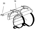
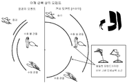
도 1은 사용자의 상지에 부착된 프레임에 수동 관절을 통해 장착된 복강경 기구, 및 외과 의사와 복강경 기구 사이의 전기기계적 방식의 인터페이스를 도시하는 본 발명의 일 실시 형태에 따른 사시도이다.
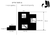
도 2는 외과 의사의 팔에 부착된 프레임 및 수동 관절에 프레임을 연결하는 조절 가능한 링크의 체인(붐(boom) 조절 시스템)을 도시하는 본 발명의 일 실시 형태에 따른 사시도이다.
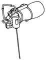
도 3은 인터페이스 및 복강경 기구 사이의 능동 관절을 도시하는 본 발명의 일 실시 형태에 따른 사시도이다.
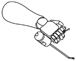
도 4는 인터페이스 및 복강경 기구 사이의 수동 관절을 도시하는 본 발명의 일 실시 형태에 따른 사시도이다.
도 5 내지 9는 복강경 기구를 잡는 여러 가지 구성을 도시하는 본 발명의 일 실시 형태에 따른 사시도이다.
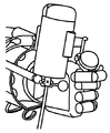
도 10은 복강경 기구의 손바닥 및 손가락 작동을 도시하는 본 발명의 일 실시 형태에 따른 사시도이다.
도 11은 복강경 기구가 인터페이스 상에 장착되는 방식을 도시하는 본 발명의 일 실시 형태에 따른 사시도이다.
도 12는 복강경 기구의 전후 틸팅을 도시하는 본 발명의 일 실시 형태에 따른 사시도이다.
도 13은 복강경 기구의 좌우 틸팅을 도시하는 본 발명의 일 실시 형태에 따른 사시도이다.
도 14 내지 15는 복강경 기구의 동작 자유도를 도시하는 본 발명의 일 실시 형태에 따른 사시도이다.
도 16은 복강경 기구의 각도 변위를 도시하는 본 발명의 일 실시 형태에 따른 사시도이다.
도 17은 우측 기구 위치로부터 중앙 위치까지 기구 동작의 시뮬레이션을 도시하는 도면이다.
도 18은 특정 기구 동작으로 인한 어깨 근육의 모멘트를 도시하는 도면이다.
도 19는 기구를 잡는 각 방식에 따라 발생하는 손바닥과 팔꿈치 높이 변화를 비교하는 시뮬레이션 결과를 도시하는 도면이다.
도 20은 기구를 잡는 각 방식에 따라 발생하는 다양한 팔 관절의 동작 범위를 비교하는 시뮬레이션 결과를 도시하는 도면이다.
도 21은 복강경 기구의 이용 방법을 도시하는 본 발명의 일 실시 형태에 따른 흐름도이다.
도 22는 본 발명의 일 실시 형태에 따른 복강경 기구용 홀더의 개략도이다.
도 23a는 본 발명의 일 실시 형태에 따른 내장형 컨트롤러를 구비한 핸들의 측면도이다.
도 23b는 본 발명의 일 실시 형태에 따른 내장형 컨트롤러를 구비한 핸들의 사시도이다.
도 24a 내지 24d는 수동 관절이 정면 위치에 있는 동안에 외과 의사가 환자 신체의 절개부(미도시)에 대해 복강경 기구를 동작시키는 것을 도시하는 본 발명의 일 실시 형태에 따른 측면도이다.
도 25는 수동 관절이 외부 위치에 있는 동안에 외과 의사가 환자 신체의 절개부(미도시)에 대해 복강경 기구를 잡는 것을 도시하는 본 발명의 일 실시 형태에 따른 측면도이다.Some embodiments of the invention described herein are described by way of example only and with reference to the accompanying drawings. Referring to the drawings in detail, it should be emphasized that the illustrations are for illustrative discussion of embodiments of the invention as examples. In this regard, the description of the drawings clearly shows to those skilled in the art how the embodiments of the invention can be practiced.
BRIEF DESCRIPTION OF THE DRAWINGS Figure 1 is a perspective view in accordance with one embodiment of the present invention showing a laparoscopic instrument mounted through a passive joint in a frame attached to a user's upper limb and an electromechanical interface between the surgeon and the laparoscopic instrument.
2 is a perspective view in accordance with an embodiment of the present invention showing a frame attached to a surgeon's arm and a chain of adjustable links (a boom adjustment system) connecting the frame to the passive joint.
3 is a perspective view in accordance with an embodiment of the present invention showing an active joint between an interface and a laparoscopic device;
4 is a perspective view in accordance with an embodiment of the present invention showing passive joints between the interface and the laparoscopic instrument;
5 to 9 are perspective views according to an embodiment of the present invention showing various configurations for holding a laparoscopic instrument.
10 is a perspective view in accordance with an embodiment of the present invention showing the palm and finger operation of a laparoscopic instrument.
Figure 11 is a perspective view in accordance with an embodiment of the present invention illustrating the manner in which the laparoscopic instrument is mounted on the interface.
12 is a perspective view of an embodiment of the present invention showing the front and back tilting of the laparoscopic instrument.
13 is a perspective view of an embodiment of the present invention showing left and right tilting of a laparoscopic instrument.
14 to 15 are perspective views according to one embodiment of the present invention showing the degree of freedom of operation of the laparoscopic instrument.
16 is a perspective view of an embodiment of the present invention showing angular displacement of a laparoscopic instrument.
17 is a view showing a simulation of the mechanism operation from the right instrument position to the center position.
18 is a view showing the moment of the shoulder muscle due to the operation of the specific mechanism.
19 is a diagram showing a simulation result for comparing palm and elbow height changes occurring according to each method of holding the instrument.
FIG. 20 is a diagram showing a simulation result for comparing various motion ranges of the arm joints generated according to each method of holding the apparatus.
21 is a flow chart according to an embodiment of the present invention showing a method of using a laparoscopic instrument.
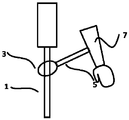
22 is a schematic view of a holder for a laparoscopic instrument according to an embodiment of the present invention.
23A is a side view of a handle having an embedded controller according to an embodiment of the present invention.
23B is a perspective view of a handle provided with a built-in controller according to an embodiment of the present invention.
24A-24D are side views in accordance with an embodiment of the present invention showing a surgeon operating a laparoscopic instrument against an incision (not shown) of a patient's body while the passive joint is in the front position.
25 is a side view in accordance with an embodiment of the present invention illustrating a surgeon holding a laparoscopic instrument against an incision (not shown) of a patient's body while the passive joint is in an external position;
본 발명은 일부 구체예에서 의료 장치, 더욱 상세하게는 외과 의사의 신체, 특히 외과 의사의 팔 및 복강경 기구 사이의 인터페이스에 관한 것이나, 이에 제한되는 것은 아니다.The present invention is in no way limited to, but in no way limited to, the interface between the medical device, and more particularly the body of the surgeon, and in particular the surgeon's arm and laparoscopic instrument in some embodiments.
본 발명의 일부 구체예는 복강경 기구의 위치 결정 및 기구 작동 기능의 분리에 관한 것이다. 본 발명의 예시적인 구체예에서 사용자의 상지 동작 및/또는 관절의 동작은 기구의 위치 결정을 바람직한 지점 및 올바른 방향으로 가능하게 한다. 사용자의 다른 신체 부위, 주로 손가락은 기구의 작동 동작을 실행시킨다.Some embodiments of the present invention relate to the positioning of the laparoscopic instrument and the separation of the instrument operating function. In an exemplary embodiment of the invention, the user's upper limb motion and / or the motion of the joint enable positioning of the instrument in the desired location and in the right direction. Other body parts of the user, mainly the fingers, perform the operation of the device.
시장에서 구입할 수 있는 기존 기구를 이용하여, 외과 의사는 통상적으로 두 가지 기능용 수술 기구 핸들을 사용한다. 첫째, 외과 의사는 바람직한 위치에서 기구를 잡아야 한다. 둘째, 외과 의사는 잘 알려진 바와 같이 레버 또는 다른 메커니즘의 누름/이동/당김/회전에 의해 기구를 작동시켜야 한다. 종종 이들 기능 사이에 충돌이 있다. 필요한 작동 위치에서 기구를 잡기 위해, 때때로 외과 의사는 불편하거나 불가능한 위치에서 기구를 작동시킬 필요가 있을 수 있다.Using existing instruments available on the market, surgeons typically use two functional surgical instrument handles. First, the surgeon must hold the instrument in the desired position. Second, the surgeon must operate the instrument by pressing / moving / pulling / rotating the lever or other mechanism as is well known. Often there is a conflict between these functions. Sometimes the surgeon may need to operate the instrument in an uncomfortable or impossible position, in order to hold the instrument in the required operating position.
인간 팔은 제한된 방향으로만 움직이거나/구부릴 수 있다. 전혀 할 수 없는 특정 동작, 및 관절에 통증 또는 손상을 유발하는 특정 동작이 있다. 어깨, 팔꿈치 및 손목은 팔의 동작을 위한 주요 관절이다. 그러나, 이들 인간 관절은 만능 관절이 아니고 무제한 범위의 동작을 갖지 못한다. 예를 들어, 기구가 외과 의사의 손바닥을 따라 잡히고 팔의 축과 기본적으로 평행하게 연장될 경우, 수동 관절 없이 복강경 기구를 잡는 것과 비교할 때, 일반적으로 외과 의사는 작은 동작을 이용하여 신체의 측면을 향해 기구를 배향시키고 적절한 절개부를 만들며 기구를 작동시킬 수 있다.The human arm can only move / bend in a limited direction. There are certain behaviors that can not be done at all, and certain behaviors that cause pain or damage to the joints. The shoulders, elbows and wrists are the main joints for the movement of the arms. However, these human joints are not universal joints and do not have an unlimited range of motion. For example, when an instrument is caught by the surgeon's palm and extends essentially parallel to the axis of the arm, the surgeon typically uses a small motion to position the side of the body It is possible to orient the instrument towards the instrument, make an appropriate incision, and operate the instrument.
외가 의사가 그의 손바닥을 따라 복강경 기구를 갖고 기구가 팔의 축과 기본적으로 평행하게 연장될 경우, 외과 의사는 환자의 위에서 쉽게 작업할 수 없다. 이것은 외과 의사의 어깨와 손목이 이러한 방향으로 기구를 작동시키기에 충분한 범위의 동작을 갖지 못하기 때문이다. 외과 의사가 환자의 측면에서 작업할 수 있는 동안에, 약 45도(환자의 위에서 작업할 때의 절반)로 움직이면, 그의 손목은 필요한 방향으로 움직이거나 구부릴 수 없기 시작한다. 이에 따라, 외과 의사는 통상적인 바와 같이 그의 손바닥을 따라 기구를 배치할 경우 복강경 기구를 작동시킬 수 있는 범위에서 제약을 받는다.A surgeon can not easily work on the patient if the surgeon has a laparoscopic instrument along his or her palms and the instrument extends essentially parallel to the axis of the arm. This is because the surgeon's shoulders and wrists do not have a sufficient range of motion to actuate the instrument in this direction. While the surgeon is able to work on the patient's side, moving about 45 degrees (half the time when working on the patient's side), his wrist starts moving or bending in the required direction. As a result, the surgeon is limited in the extent to which it can operate the laparoscopic instrument if the instrument is placed along the palm of his hand, as is typical.
기구를 잡기 위한 수동 관절(passive joint)을 사용할 경우 좌우로 기구의 동작 범위가 더 좋아지고, 반면에 종래처럼 기구를 잡을 경우 상기 범위의 절반만 가능하다. 또한, 수동 관절을 이용하는 동안에 외과 의사가 행한 작업량은 종래처럼 잡는 것에 비해 더 적어진다.The use of a passive joint for holding the instrument improves the operating range of the instrument to the left and right, while only half of the range is possible if the instrument is held as before. In addition, the amount of work done by a surgeon while using a passive joint is much smaller than the conventional one.
dH는 팔꿈치의 최저 위치로부터 팔꿈치의 최고 위치까지 높이 변화를 나타내고, 위치 에너지 변화 및 외과 의사의 어깨 근육에 의해 행해진 작업과 직접 관련된다.dH represents the height change from the lowest position of the elbow to the highest position of the elbow and is directly related to the changes in position energy and work done by the surgeon's shoulder muscles.
도 17은 우측 기구 위치로부터 중앙 위치까지 세 가지 형태의 기구(두 가지는 기구를 잡기 위한 수동 관절을 갖고, 하나는 통상적인 장착대이다)의 기구 동작의 시뮬레이션을 도시한다.Fig. 17 shows a simulation of the mechanism operation of three types of instruments from the right instrument position to the center position (two have passive joints for holding the instrument and one is a conventional mount).
유사하게, 원위에서 손 방향으로 또는 중앙에서 손 방향으로와 같이 기구를 다른 방향으로 배향시킬 경우, 외과 의사는 환자에 대한 특정 방향에서 기구를 작동시킬 수 없게 되는데, 그 이유는 그의 어깨, 팔꿈치 및/또는 손목 동작의 필요한 결합 범위를 갖지 못하기 때문이다. 도 17에 도시된 바와 같이, 팔꿈치 동작의 영역(envelope) 및 손바닥 동작의 영역이 있다. 달리 말하면, 팔꿈치와 손목 관절은 제한된 방향으로만 움직일 수 있다. 외과 의사가 기구를 어떻게 잡는지에 따라 팔 관절의 특정 동작 방향이 물리적으로 불가능하거나 물리적으로 힘들 수 있기 때문에, 기구를 사용할 수 있는 범위가 제한적이다.Similarly, when the instrument is oriented in the other direction, such as in the hand or in the center to hand direction, the surgeon will not be able to operate the instrument in a particular direction to the patient because his shoulders, And / or does not have the necessary binding range of wrist motion. As shown in Fig. 17, there is an envelope of the elbow motion and a region of the palm motion. In other words, the elbows and wrists can only move in a limited direction. Depending on how the surgeon grips the device, the range of use of the device is limited because the specific direction of movement of the arm joint may be physically impossible or physically difficult.
더욱 구체적으로, 손바닥과 팔꿈치 동작의 영역이 도 17에 도시되어 있다. 원통형 영역은 세 가지 치수를 갖는다. 아크는 동작의 각도를 나타내고, 높이는 일을 나타낸다. 세 번째 치수는 영역의 반경이다. 반경이 클수록, 외과 의사의 근육이 균형을 맞추어야 할 모멘트가 커진다. 이것은 인체공학의 품질, 근육의 피로도 및 외과 의사의 작업량과 관련된다.More specifically, the areas of palm and elbow motion are shown in Fig. The cylindrical region has three dimensions. The arc represents the angle of motion, and the height represents the work. The third dimension is the radius of the area. The larger the radius, the greater the moment that the surgeon's muscles must balance. This relates to ergonomic quality, muscle fatigue and surgeon's workload.
도 17에 도시된 바와 같이, 예를 들어, 복강경 기구의 위치는 가능한 동작의 영역을 결정한다. 특히, 최저 위치로부터 중앙 위치까지 기구를 이동시키는데 팔꿈치 동작이 얼마나 필요한가를 나타낸다. 기구를 잡는 수동 관절을 사용할 경우, 팔꿈치 동작은 최소량이 되면서 기구 동작의 영역 크기는 증가한다.As shown in FIG. 17, for example, the position of the laparoscopic instrument determines the area of possible operation. In particular, it indicates how much elbow motion is required to move the instrument from the lowest position to the center position. When using a passive joint that holds the instrument, the area size of the instrument motion increases as the elbow motion becomes minimal.
도 17은 수술 기구를 잡는 세 가지 방식, 즉 손바닥 외부(또는 손바닥 뒤)에 위치하여 기구를 잡는 수동 관절, 손바닥 내부에 위치하여 기구를 잡는 수동 관절, 및 통상적인 기구 잡는 방식 사이의 차이를 도시한다. 통상적인 기구 잡는 방식의 경우, 동작 영역이 상대적으로 작다. 손바닥 외부에 위치하여 기구를 잡는 수동 관절을 사용할 경우, 동작을 수행하는 동안에 작업량이 감소하면서 동작 영역의 크기가 증가한다. 또한, 이 방법은 근육에 최소 모멘트를 요구한다.Fig. 17 shows the difference between the three ways of holding the surgical instrument, i.e., the passive joint located outside the palm (or behind the palm) and holding the instrument, the passive joint located within the palm and holding the instrument, do. In the case of the conventional mechanism holding method, the operating area is relatively small. When using a passive joint that is located outside the palm of the hand and holding the device, the amount of work is reduced while the operation is performed, increasing the size of the operating area. In addition, this method requires a minimum moment on the muscles.
손의 뒤에 위치하여 기구를 잡는 수동 관절은 가장 좋은 해결수단을 제공하고, 최소한의 팔꿈치 동작으로 가장 큰 영역을 갖는다. 이것은 이점이다. 수동 관절 없이 큰 영역을 얻기 위해서는, 팔꿈치 동작을 현저하게 증가시킬 필요가 있다. 여기에 개시된 본 발명의 구체예는 효과적인데, 상술한 바와 같이, 기구를 잡는 수동 관절을 사용함으로써, 외과 의사가 더 적은 노력으로 그리고 더 인체공학적으로 기구를 동작시킬 수 있기 때문이다.The passive joints located behind the hands and holding the instruments provide the best solution and have the largest area with minimal elbow motion. This is an advantage. In order to obtain a large area without a passive joint, it is necessary to significantly increase the elbow motion. Embodiments of the invention disclosed herein are effective because, as described above, the use of a passive joint to hold the device allows the surgeon to operate the device with less effort and more ergonomically.
외과 수술 중에, 외과 의사의 상부 팔이 움직인다. 상부 팔 동작이 클수록, 상부 팔의 물리적 스트레스가 커진다. 따라서, 여기에 기술된 바와 같이 기구를 잡는 수동 힌지(hinge)를 사용하는 것이 유리한데, 그 이유는 기구 동작이 최대화되고, 동시에 상부 팔의 실제 동작이 최소화되며, 상부 팔의 스트레스가 감소하기 때문이다.During surgery, the upper arm of the surgeon moves. The greater the upper arm motion, the greater the physical stress of the upper arm. Thus, it is advantageous to use a manual hinge to hold the instrument as described herein, because the mechanism operation is maximized, at the same time the actual motion of the upper arm is minimized and the stress on the upper arm is reduced to be.
따라서, 외과 의사의 팔 동작을 최소화하고 팔 동작의 효율을 최적화하는 것이 목적이다. 동작이 적을수록, 팔꿈치와 같은 팔 관절의 스트레스가 더 감소한다는 것을 알 수 있다.Therefore, the aim is to minimize the arm motion of the surgeon and optimize the efficiency of the arm motion. The lower the motion, the more the stress on the elbow and the arm joints decreases.
때때로 외과 의사는 환자 신체의 다른 측면에서 삽입되는 기구를 잡을 필요가 있다. 이것은 기구용 긴 핸들 또는 팔의 물리적 제약을 요구하며, 외과 의사에게는 문제가 될 수 있다. 기구를 잡는 수동 관절을 사용함으로써, 외과 의사는 편안한 영역에서 작업하고 스트레스가 심한 작업을 피할 능력을 갖게 되며, 이에 따라 기구 제어를 향상시킨다.Occasionally a surgeon needs to grab a device that is inserted from the other side of the patient's body. This requires physical constraints on long handles or arms for the instrument and can be problematic for the surgeon. By using a passive joint to hold the instrument, the surgeon has the ability to work in a comfortable area and avoid stressful work, thereby improving instrument control.
동일한 사안이 어깨에도 해당된다. 사용자 또는 외과 의사가 통상적인 방식으로 기구를 잡으면서 그의 어깨를 사용하여 기구 동작을 실행시킨다면, 기구 동작 영역이 증가할 수 있다. 그러나, 기구를 잡는 수동 관절을 이용함으로써, 외과 의사는 어깨를 움직일 필요가 없게 되며, 수동 관절의 사용에 의해 인체공학적 작업이 더 효율적으로 이루어진다.The same applies to the shoulder. If the user or surgeon uses the shoulder to perform instrument operation while holding the instrument in the usual manner, the instrument operating area may increase. However, by using a passive joint to hold the device, the surgeon does not need to move the shoulder, and the use of passive joints makes the ergonomic work more efficient.
도 18은 우측으로부터 중앙 평면까지 기구를 움직이면서 기구를 잡는 여러 가지 방식에 의해 발생하는 어깨 근육의 모멘트를 나타내는 시뮬레이션 결과를 도시한다.18 shows a simulation result showing the moments of the shoulder muscles caused by various methods of holding the device while moving the device from the right side to the center plane.
어깨 또는 팔꿈치의 모멘트는 상지(즉, 상부 팔)를 동작시키거나 안정화시키도록 어깨 또는 팔꿈치 근육에 의해 가해지는 힘을 말한다.The moment of the shoulder or elbow refers to the force exerted by the shoulder or elbow muscles to actuate or stabilize the upper limb (i.e., the upper arm).
어깨 근육은 기구, 팔뚝 및 팔의 무게에 대항하여 작용하고, 팔꿈치 근육은 기구 및 팔뚝의 무게에 대항하여 작용하므로, 근육에 의해 가해지는 힘은 기구 자체의 모멘트보다 더 크다.The shoulder muscles act against the weight of the instrument, forearm and arm, and the elbow muscles act against the weight of the instrument and forearm, so that the force exerted by the muscles is greater than the moment of the instrument itself.
힘이 클수록, 피로가 커지고 근육 통증이 커진다. 아크의 반경은 어깨 또는 팔꿈치 관절로부터 무게 중심까지의 수평 거리를 나타낸다.The greater the force, the greater the fatigue and the greater the muscle pain. The radius of the arc represents the horizontal distance from the shoulder or elbow joint to the center of gravity.
반경이 클수록, 모멘트가 커진다. 이 개념을 설명하기 위해, 사람의 손에 잡힌 무거운 여행 가방을 생각해 보라. 사람은 자기 신체에 가능한 가깝게 가방을 잡으려 할 것이다. 그 이유는 이 위치에서 여행 가방이 어깨 바로 밑에 있기 때문이다. 따라서 근육에 의해 가해지는 힘과 반경이 최소가 된다. 다른 한편, 사람의 손에 여행 가방이 있고 손을 측면으로 올릴 경우를 생각해 보라. 이 위치에서 여행 가방은 어깨로부터 멀리 있다. 따라서 반경이 더 커지고 이 위치를 유지하기 위해 더 많은 근육 힘이 필요해진다.The larger the radius, the larger the moment. To illustrate this concept, think of a heavy suitcase in the hands of a man. A person will try to hold the bag as close to his body as possible. The reason for this is that the suitcase is just below the shoulder in this position. Thus minimizing the force and radius exerted by the muscles. On the other hand, consider the case where a person has a suitcase in his hand and raises his hand to the side. In this position the suitcase is far from the shoulders. Thus, the radius is larger and more muscle force is needed to maintain this position.
이 개념은 복강경 수술에도 동일하게 적용된다. 외과 의사는 일반적으로 어깨의 모멘트를 줄이길 원한다. 반경을 더 작게 함으로써, 외과 의사에게는 작동 위치를 유지하는데 필요한 근육 힘이 적어지고 피로와 불편도 적어진다. 여기에 개시된 기구 잡는 관절 및 인터페이스를 이용할 경우, 외과 의사는 반경을 줄이고 근육 힘을 더 적게 사용할 수 있다. 따라서 피로와 불편이 더 적어진다.This concept applies equally to laparoscopic surgery. Surgeons generally want to reduce the moment on their shoulders. By making the radius smaller, the surgeon has less muscle strength and less fatigue and inconvenience to maintain the operating position. Using the instrument grip joints and interfaces disclosed herein, the surgeon can reduce the radius and use less muscle force. So less fatigue and inconvenience.
도 19는 기구를 잡는 여러 가지 방식에 의해 발생하는 손바닥과 팔꿈치의 높이 변화를 비교하는 시뮬레이션 결과를 도시한다. 도면은 dH의 차이(중력에 대항한 일을 결정하는 높이 차이)를 보여준다. 높이 차이가 작을수록 외과 의사가 가하는 힘이 적어진다.Fig. 19 shows a simulation result comparing the changes in the height of the palm and the elbow caused by various methods of holding the instrument. The figure shows the difference in dH (height difference to determine work against gravity). The smaller the height difference, the less force the surgeon exerts.
외과 의사가 동일한 위치를 얻기 위해 중력에 대항하여 더 일할 필요가 있다면, 외과 의사의 능률은 줄고 피로가 더 일찍 올 것이다.If a surgeon needs to work more against gravity to get the same position, the surgeon's efficiency will be less and fatigue will come earlier.
따라서, 팔꿈치와 손바닥 동작을 줄임으로써, 외과 의사는 중력에 대항한 일을 줄일 수 있다. 여기에 개시된 기구 잡는 관절 및 인터페이스는 외과 의사의 능률을 늘리고 중력에 대항한 일을 줄인다.Thus, by reducing the elbow and palm motion, the surgeon can reduce work against gravity. The instrumental grips and interfaces disclosed herein increase the efficiency of the surgeon and reduce work against gravity.
도 20은 기구를 잡는 여러 가지 방식에 의해 발생하는 다양한 팔 관절의 동작 범위를 비교하는 시뮬레이션 결과를 도시한다.FIG. 20 shows a simulation result for comparing the range of motion of various arm joints caused by various methods of holding the instrument.
복강경 기구를 이용할 경우, 외과 의사는 기구가 사용될 수 있는 동작 범위를 갖는다. 도 20에 도시된 바와 같이, 예를 들어, 복강경 기구를 잡는 종래 또는 통상적인 방법은 상대적으로 제한된 동작 범위를 갖는다. 이에 비해, 수동 관절이 기구를 잡는데 사용될 경우, 외과 의사의 동작 패턴이 변하고 외과 의사 팔의 포텐셜(potential) 범위가 극적으로 증가한다. 수동 볼 관절을 사용할 경우, 기구 동작 범위는 더욱 증가한다.When using a laparoscopic instrument, the surgeon has a range of motion in which the instrument can be used. As shown in FIG. 20, for example, a conventional or conventional method of holding a laparoscopic instrument has a relatively limited range of motion. In contrast, when the passive joint is used to hold the instrument, the surgeon's motion pattern changes and the potential range of the surgeon's arm dramatically increases. When a manual ball joint is used, the operating range of the mechanism is further increased.
동작 범위는 복강경 기구 전체 동작을 의미한다. 이것은 환자 신체의 절개부에 대해 기구 각도를 변화시키는 외과 의사의 능력을 말한다.The operating range refers to the entire operation of the laparoscopic instrument. This refers to the surgeon's ability to vary the instrument angle relative to the incision of the patient's body.
기구를 잡는 수동 관절은 손 동작을 최소화하면서 얻게 될 기구 각도의 변화를 크게 한다. 수동 관절에 대해, 아크(각도 및 반경)는 동일하고, 이들은 도 20에 결합한다. 도시된 바와 같이, 동작이 적을수록 높이 변화가 적고, 반경이 작을수록 더 좋아진다.The passive joints that hold the instrument increase the change in the instrument angle that will be achieved while minimizing hand motion. For passive joints, the arcs (angles and radii) are the same and they couple to Fig. As shown, the smaller the movement, the smaller the height variation, and the smaller the radius, the better.
요컨대, 본 발명의 기본 개념은 복강경 기구의 위치 결정 및 기구 작동 기능이 분리된다는 것이다. 사용자의 상지(예를 들어, 팔뚝 및/또는 손) 동작 및/또는 관절의 동작은 기구의 위치 결정을 바람직한 위치 및 방향으로 가능하게 한다. 사용자의 손가락은 기구의 작동 동작을 실행시킨다.In short, the basic concept of the present invention is that the positioning and instrument operating functions of the laparoscopic instrument are separate. The user's upper limb (e.g., forearm and / or hand) motion and / or motion of the joint enables positioning of the instrument in the desired position and orientation. The user's finger executes the operation of the apparatus.
이러한 복강경 기구의 위치 결정 및 기구 작동 기능의 분리는 외과 의사가 현재 복강경 기구를 사용하는 방식과 비교하여 유리하다. 현재, 외과 의사는 손가락을 이용하여 기구의 위치를 잡고 기구를 작동한다. 이로 인해 외과 의사는 장시간 동안 비-인체공학 방식으로 일하게 되고, 손가락 동작에 제한을 가진 채 기구를 작동시키게 된다.The positioning of the laparoscopic instrumentation and the separation of the instrumentation function are advantageous compared to the way the surgeon currently uses the laparoscopic instrument. Currently, the surgeon uses a finger to position the instrument and operate the instrument. This causes the surgeon to work non-ergonomically for a long period of time and operate the instrument with limitations on finger motion.
도 21은 예를 들어 복강경 기구의 이용 방법을 나타내는 흐름도로서, 상기 방법은 사용자의 상지(일반적으로 팔뚝 또는 손)에 프레임을 부착하는 단계; 복강경 기구용 프레임 상에 장착대의 위치를 결정하는 단계; 장착대에 복강경 기구를 고정하는 단계; 복강경 기구에 컨트롤러를 작동되게 연결하고 컨트롤러가 사용자의 손에 의해 작동되도록 구성하는 단계; 및 컨트롤러의 작동 및/또는 사용자의 상부 팔 동작에 의해 복강경 기구의 동작을 개시하는 단계를 포함한다.21 is a flow chart illustrating a method of using a laparoscopic instrument, for example, comprising the steps of attaching a frame to a user's upper limb (generally the forearm or hand); Determining a position of the mounting table on the frame for the laparoscopic instrument; Securing a laparoscopic instrument to the mounting table; Operatively connecting the controller to the laparoscopic instrument and configuring the controller to be operated by a user's hand; And initiating operation of the laparoscopic instrument by operation of the controller and / or upper arm of the user.
사용자의 상지(일반적으로 팔뚝 및/또는 손) 동작 및/또는 관절의 동작은 기구의 위치 결정을 바람직한 지점 및 올바른 방향으로 가능하게 한다. 사용자의 손가락은 기구의 작동 동작을 실행시킨다.The user's upper limb (generally forearm and / or hand) motion and / or motion of the joint enable positioning of the instrument in the desired position and in the right direction. The user's finger executes the operation of the apparatus.
여기의 개시 내용에서 어깨 동작은 도시되지 않지만, 때때로 어깨는 동작에 참여할 수 있다. 여기에 개시된 복강경 기구를 장착 및 이용하는 방법 및 장치는 외과 의사가 어깨 사용을 최소화하고자 하는 상황을 고려한다. 하루에 몇 시간씩 어깨를 위로 올리거나 아래에 누르면서 수술하는 외과 의사에게는 만성 근육 통증이 발병할 것이고, 척추(목 및 하부 등) 및 어깨뼈 사이에 만성 압력이 발생할 것이다. 바람직하게는, 이것이 복강경 기구가 어깨 동작 없이 동작해야 하는 이유이다.In the present disclosure, the shoulder motion is not shown, but sometimes the shoulder can participate in the motion. The method and apparatus for mounting and using the laparoscopic instrument described herein contemplates situations in which the surgeon wishes to minimize shoulder use. Surgical surgeons with shoulder up or down for several hours a day will develop chronic muscle pain, and chronic pressure will develop between the spine (neck and lower back) and the shoulder bone. Preferably, this is why the laparoscopic instrument should operate without shoulder movement.
본 발명의 일부 구체예에 따르면, 복강경 기구를 이용하는 기본 방법 또는 방식은 먼저 팔뚝 또는 손과 같은 사용자의 상지에 프레임을 부착하는 것이다. 프레임은 이후 기술되는 어떠한 형태도 될 수 있다. 프레임은 팔 또는 손에 쉽게 끼워져야 한다.According to some embodiments of the present invention, a basic method or method using a laparoscopic instrument is to first attach a frame to the upper limb of a user, such as the forearm or hand. The frame may be any of the forms described below. The frame should fit easily into the arm or hand.
복강경 기구용으로 적합한 장착대는 프레임 상에 설치된다. 일부 구체예에서 장착대는 프레임과 일체로 제작될 수 있다. 일부 구체예는 프레임에 특정 방식으로 고정되는 별개의 장착대를 포함할 수 있다. 장착대는 기구 샤프트의 특정 동작 범위를 허용하는 관절을 포함할 수 있다. 수동 또는 능동 관절이 사용될 수 있다. 능동 관절은 기구의 샤프트를 동작시키는 특정 메커니즘을 갖고, 포트를 구비하는 기구를 지지할 필요 없이 기구의 바람직한 방향과 위치를 설정하는 능력을 갖는 것이다. 수동 관절은 기구의 자유로운 배향을 허용하는 것이지만, 기구는 지지대를 가질 필요가 있다(그렇지 않으면, 기구는 중력에 의해 결정되는 정지점으로 이동할 것이다).A mounting plate suitable for a laparoscopic instrument is mounted on the frame. In some embodiments, the mount may be fabricated integrally with the frame. Some embodiments may include separate mounts fixed to the frame in a particular manner. The mount may include a joint that allows a particular range of motion of the instrument shaft. Manual or active joints can be used. The active joint has a specific mechanism for operating the shaft of the instrument and has the ability to set the desired orientation and position of the instrument without having to support the instrument with the port. Passive joints allow free orientation of the device, but the device needs to have a support (otherwise the device will move to a stop point determined by gravity).
복강경 기구의 샤프트는 장착대(또는 관절)에 삽입되고 고정된다. 선택적으로, 샤프트는 단단히 고정되면서 장착대 또는 관절 내에서 기울거나 회전하지 않는다. 다른 구체예에서, 기구의 하우징이 고정되면서 전체 샤프트가 자유롭게 회전할 수 있다.The shaft of the laparoscopic instrument is inserted and fixed in the mount (or joint). Optionally, the shaft is rigidly secured and does not tilt or rotate within the mount or joint. In another embodiment, the entire shaft can freely rotate while the housing of the instrument is secured.
본 발명의 일부 구체예에 따르면, 컨트롤러는 복강경 기구에 작동되게 연결되고 외과 의사의 손에 의해 작동되도록 구성된다.According to some embodiments of the present invention, the controller is operatively connected to the laparoscopic device and configured to be operated by a surgeon's hand.
본 발명의 일 실시 형태에서, 복강경 기구의 동작은 컨트롤러의 작동 및/또는 사용자의 하부 팔의 동작에 의해 시작된다. 기구의 부품이 장착대(또는 관절)에 잡히고 장착대는 팔에 대해 고정된 채 있으므로, 팔 동작은 반드시 기구를 동작시킨다. 기구 부품의 동작은 컨트롤러를 이용하여 능동 관절을 작동시킴으로써 달성될 수 있다.In one embodiment of the invention, the operation of the laparoscopic device is initiated by operation of the controller and / or operation of the user's lower arm. Since the part of the instrument is caught on the mounting table (or joint) and the mounting stand is fixed with respect to the arm, the arm operation necessarily activates the instrument. The operation of the mechanical component can be achieved by operating the active joint using the controller.
본 발명의 일 실시 형태에서, 복강경 기구의 동작은 어깨뼈(견갑골, 빗장뼈) 동작, 팔뼈(위팔뼈, 노뼈, 자뼈) 동작, 손바닥 동작의 조합에 의해 및/또는 외과 의사의 어깨, 팔꿈치, 손목 및 손가락을 이용함으로써 실행된다.In one embodiment of the invention, the operation of the laparoscopic instrument is performed by a combination of shoulder bone (scapula, clavicular) motion, arm bone (upper arm, Wrists and fingers.
인터페이스에 장착된 관절을 이용할 경우, 외과 의사 또는 사용자는 사용자의 팔에 대한 상대 위치에서 복강경 기구의 샤프트를 유지할 수 있다.With the joints mounted on the interface, the surgeon or user can maintain the shaft of the laparoscopic instrument at a relative position to the user's arm.
일부 구체예에서, 팔에 대해 복강경 기구의 샤프트의 상대 위치를 변화시키는 것이 가능하다. 관절은 상대 위치에서 이 변화를 용이하게 한다. 이것은 도 16과 관련하여 이하에서 기술되는 바와 같이, 복강경 기구의 샤프트 및 외과 의사의 팔 사이의 각도를 변화시키는 것을 수반할 수 있다. 또한, 이것은 도 14 내지 15와 관련하여 이하에서 기술되는 바와 같이, 장착대 또는 관절에 대해 복강경 기구의 샤프트를 틸팅하는 것을 수반할 수 있다.In some embodiments, it is possible to vary the relative position of the shaft of the laparoscopic instrument relative to the arm. Joints facilitate this change in relative position. This may involve varying the angle between the shaft of the laparoscopic instrument and the surgeon's arm, as described below in connection with FIG. This can also entail tilting the shaft of the laparoscopic instrument relative to the mount or joint, as described below with respect to Figures 14-15.
일부 구체예에 따르면, 기구의 작동부는 장치를 제어하는 것과 분리되고 기구의 샤프트를 잡는 관절은 컨트롤러와 분리된다. 복강경 기구의 샤프트는 외과 의사/사용자의 팔과 반드시 동축일 필요가 없고 및/또는 복강경 기구의 샤프트는 컨트롤러와 반드시 동축일 필요가 없다.According to some embodiments, the actuating portion of the mechanism is separate from the control of the device, and the joint holding the shaft of the mechanism is separate from the controller. The shaft of the laparoscopic instrument does not necessarily co-axial with the surgeon / user's arm and / or the shaft of the laparoscopic instrument does not necessarily co-exist with the controller.
관절을 통해 프레임에 복강경 장치를 연결할 경우, 팔과 손목 동작을 뒤틀 필요 없이 복강경 장치를 동작시킬 수 있다. 이것은 외과 의사의 팔 또는 컨트롤러와 동축이지 않은 복강경 기구의 샤프트에 의해 달성된다. 이를 달성하기 위해, 복강경 기구는 프레임에 대해 바람직한 위치에 위치하는 관절을 통해 프레임에 연결된다. 관절이 수동이고 자유로운 동작을 갖는다면, 기구에 대한 추가적인 지지 없이, 복강경 장치는 중력 정지점에 도달할 때까지 동작할 것이고, 프레임과 사용자 팔에 대해 일정 각도에서 머물 것이다. 따라서, 일부 구체예에서, 장치는 수동 관절용 브레이크 메커니즘을 포함할 수 있어서, 복강경 장치는 프레임에 대해 바람직한 각도에서 유지될 것이다.If you connect the laparoscopic device to the frame through the joint, you can operate the laparoscopic device without having to twist your arms and wrist movements. This is accomplished by a surgeon's arm or shaft of a laparoscopic instrument that is not coaxial with the controller. To achieve this, the laparoscopic instrument is connected to the frame through a joint located at a desired position relative to the frame. If the joint has manual and free motion, without additional support for the instrument, the laparoscopic device will operate until it reaches the gravitational stop point and will stay at an angle to the frame and the user arm. Thus, in some embodiments, the device may include a brake mechanism for a passive joint so that the laparoscopic device will be maintained at a desired angle relative to the frame.
도 22는 복강경 기구용 홀더의 일 구체예에 대한 개략도이다.22 is a schematic view of one embodiment of a holder for a laparoscopic instrument.
도 22에 개략적으로 도시된 바와 같이, 가장 단순한 기본 형태에서, 일 구체예는 관절(3)에 잡힌 복강경 기구의 부품(1)을 포함한다. 관절(3)은 외과 의사의 팔(7)(또는 손)에 특정 방식으로 부착된 지지 부재(5) 상에 지지된다. 기구의 작동 요소를 이용할 경우, 컨트롤러(미도시)는 복강경 기구에 작동되게 연결되고 사용자의 손에 의해 작동되도록 구성된다.As shown schematically in Fig. 22, in its simplest basic form, one embodiment includes a
이 구성으로 인해 복강경 기구의 기구 위치 동작용 작동부는 컨트롤러와 분리될 수 있다. 복강경 기구의 샤프트는 외과 의사의 팔과 반드시 동축일 필요가 없고 및/또는 복강경 기구의 샤프트는 컨트롤러와 반드시 동축일 필요가 없다.Due to this configuration, the instrumental positioning operative portion of the laparoscopic instrument can be separated from the controller. The shaft of the laparoscopic instrument does not necessarily have to be coaxial with the surgeon's arm and / or the shaft of the laparoscopic instrument does not necessarily have to be coaxial with the controller.
본 발명의 예시적인 구체예에서, 복강경 기구의 위치 결정 및 기구 작동 기능은 분리된다. 사용자 팔 동작 및/또는 관절 동작은 기구의 위치 결정을 바람직한 지점 및 올바른 방향으로 가능하게 한다. 사용자의 손가락은 기구의 작동 동작을 실행시킨다.In an exemplary embodiment of the invention, the positioning and instrument operating functions of the laparoscopic instrument are separate. User arm motion and / or joint motion enable positioning of the instrument in the desired location and in the right direction. The user's finger executes the operation of the apparatus.
본 발명의 적어도 하나의 구체예를 상세하게 설명하기 전에, 본 발명은 이하의 설명에 기재되고 및/또는 도면 및/또는 실시예에 예시되는 구성요소 및/또는 방법의 구성 및 배치에 대한 상세사항에 제한되지 않는다. 본 발명은 다른 구체예일 수 있거나, 다양한 방식으로 실시되거나 수행될 수 있다.BRIEF DESCRIPTION OF THE DRAWINGS Before describing in detail one or more embodiments of the present invention, the present invention will be described in detail in the following description and / or detailed description of the components and / or arrangements of the components and / or methods illustrated in the drawings and / . The invention may be embodied in other specific forms, or may be practiced or carried out in various ways.
도면은 참고하면, 도 1은 사용자의 상지에 부착된 프레임에 수동 관절을 통해 장착된 기구, 및 외과 의사와 복강경 기구 사이의 수동 또는 전기기계적 방식의 인터페이스를 도시하는 본 발명의 일 실시 형태에 따른 사시도이다.Referring to the drawings, FIG. 1 is a perspective view of a device attached through a passive joint to a frame attached to a wearer's upper limb, and a manual or electromechanical interface between a surgeon and a laparoscopic device, according to an embodiment of the present invention. It is a perspective view.
도 1은 일부 구체예에 따라 두 기능 사이에 분리가 있는 것을 예시한다. 특히, 기구의 작동부는 기구 제어와 분리된다. 수동적인 구체예 및 전기기계적인 구체예 모두가 실행될 수 있다.Figure 1 illustrates that there is separation between the two functions according to some embodiments. Particularly, the operating part of the mechanism is separated from the mechanism control. Both passive and electromechanical embodiments can be practiced.
예시적인 수동적인 구체예에서, 컨트롤러(8)는 사용자의 손에 안착된다. 일부 구체예에 따르면, 스트랩(strap)이 컨트롤러(8)를 잡는데 사용될 수 있다. 직접적인 기계적 연결부(10)는 컨트롤러로부터 기구(6)의 작동 요소까지 연장된다. 기구가 동작하거나 활성화되는 방식은 컨트롤러가 사용자에 의해 작동되는 방식에 기반한다.In an exemplary passive embodiment, the
프레임 또는 슬리브(sleeve)의 특정 설계 및 구성은 본 발명에서 반드시 중요한 것이 아니다. 일부 구체예는 개방형 프레임을 이용하고, 반면에 다른 구체예는 폐쇄형 슬리브를 이용한다. 플라스틱 또는 금속과 같이 어떠한 적절한 재료도 사용될 수 있다. 부드러운 라이닝 재료가 의사를 더 편안하게 하고 팔의 쓸림과 자극을 방지하도록 적용될 수 있다. 프레임 또는 슬리브는 관절을 잡고 팔과 관절 사이의 작동 관계를 달성하는데 사용되어서, 팔 동작이 복강경 기구를 반드시 작동시킨다.The particular design and construction of the frame or sleeve is not critical to the present invention. Some embodiments use open frames, while other embodiments use closed sleeves. Any suitable material such as plastic or metal may be used. Soft lining materials can be applied to make the doctor more comfortable and to prevent swelling and irritation of the arm. The frame or sleeve is used to hold the joint and to achieve the working relationship between the arm and the joint, so that the arm action necessarily activates the laparoscopic instrument.
다른 구체예에 대해, 사용자의 하부 팔(2)(또는 하부 팔의 일부)에 착용되는 프레임(또는 인터페이스)(4)이 존재한다. 프레임은 단순한 금속(또는 단단한 플라스틱) 프레임일 수 있다. 일 구체예는 팔(2)을 둘러싸는 다수의 링(14)을 이용한다. 안정성을 위해, 스트랩(16)이 링(14)을 연결한다. 붐(boom)(18)이 팔로부터 연장되고 그 위에 복강경 기구를 동작시키는 작동 제어부가 장착된다. 이하에서 설명되는 바와 같이, 붐은 선형으로 확대(신축) 가능하여 사용자의 팔에 대해 기구의 위치를 변화시킬 수 있다.For another embodiment, there is a frame (or interface) 4 worn on the user's lower arm 2 (or part of the lower arm). The frame may be a simple metal (or rigid plastic) frame. One embodiment uses a plurality of
도 2는 외과 의사의 팔에 부착된 프레임 및 수동 관절에 프레임을 연결하는 조절 가능한 링크의 체인을 도시하는 본 발명의 일부 구체예에 따른 사시도이다.2 is a perspective view in accordance with some embodiments of the present invention showing a frame attached to a surgeon's arm and a chain of adjustable links connecting the frame to a passive joint;
도 2에 도시된 바와 같이, 프레임의 다른 구체예는 사용자의 하부 팔(2)에 착용되는 단단한 슬리브(20)를 포함한다.As shown in FIG. 2, another embodiment of the frame includes a
도 2를 참고하면, 붐(18)은 관절식일 수 있는 링크(22)를 포함할 수 있다. 이런 식으로 팔의 길이에 대해 신축 및 확대됨과 더불어, 붐은 좌우 또는 상하로도 움직일 수 있다. 관절식 링크에 의해, 복강경 기구의 많은 다른 각도와 배향이 달성될 수 있다. 이로 인해 외과 의사는 진행되고 있는 특정 동작에 대해 가장 적합하고 효율적인 위치로 복강경 기구를 동작시킬 수 있다.Referring to FIG. 2, the
관절식 링크(22)에 의해, 붐과 복강경 기구는 많은 다른 동작 평면 및 많은 다른 각도에서 움직일 수 있다. 일단 위치가 결정되면, 링크는 선택적으로 잠긴다. 이것은 팔이 움직일 경우에도 상대 위치에서 복강경 기구의 샤프트를 유지시킨다.By articulated
일 구체예에서, 예를 들어, 각 링크는 각각의 말단부에 중심 개구를 구비한 이어(ear)를 갖는다. 인접하는 링크들은 함께 끼워져서 이들의 이어는 정렬된다. 이후, 링크는 붐의 정확한 정렬을 달성하도록 위치하고, 핀이 두 개구를 통해 삽입되어 인접한 링크를 함께 잡는다. 잠금 너트가 이들을 단단하게 잡는데 사용된다. 다양한 핀의 풀림에 의해, 링크는 많은 다른 각도 및 방향으로 움직일 수 있고, 이에 따라 붐은 다수의 위치에 위치할 수 있다. 이로 인해 바람직한 공간 위치에서 복강경 기구를 잡는 수동 관절의 조절이 가능하다.In one embodiment, for example, each link has an ear with a central opening at each end. Adjacent links fit together and their posts are aligned. The links are then positioned to achieve accurate alignment of the boom, and pins are inserted through the two openings to hold the adjacent links together. Lock nuts are used to hold them tightly. By loosening the various pins, the link can be moved in many different angles and directions, so that the boom can be located in multiple locations. This makes it possible to adjust the passive joint to hold the laparoscopic instrument at the desired spatial location.
적어도 두 가지 기본 형태의 관절, 즉 수동 관절 또는 능동 관절이 붐 상에 복강경 기구의 작동 제어부를 장착하는데 사용될 수 있다. 특히, 수동 관절은 동작을 실행시키지 못하지만 기구 샤프트 동작의 자유로운 배향을 가능하게 하며, 반면에 능동 관절은 동작을 실행시킨다. 수동 관절의 경우, 기구는 절개 지점과 같은 추가 지점에서 지지될 수 있다. 능동 관절은 관절에서 모멘트 및 일을 형성한다. 이들 힘과 모멘트는 제2지지점의 필요 없이 바람직한 위치에서 기구를 지지할 수 있다.At least two basic types of joints, passive joints or active joints, can be used to mount the operation control of the laparoscopic instrument on the boom. In particular, passive joints do not perform motion, but allow free orientation of mechanism shaft motion, while active joints perform motion. In the case of a passive joint, the instrument may be supported at an additional point, such as the incision point. Active joints form moments and work in joints. These forces and moments can support the instrument in the desired position without the need for a second fulcrum.
도 3은 프레임에 연결된 능동 관절을 도시하는 본 발명의 일부 구체예에 따른 사시도이다.Figure 3 is a perspective view in accordance with some embodiments of the present invention illustrating an active joint connected to a frame.
도 3은 능동 관절의 가능한 일 구체예를 도시한다. 붐(18)의 원위 말단부 상에 기어(24)가 설치된다. 이 기어는 복강경 기구의 샤프트(28)에 설치된 기어(26)와 맞물린다. 기어 트레인의 동작은 샤프트에 전달되고 이에 따라 기구의 작동 요소가 이용된다. 샤프트(18) 및 기어(26)를 회전시키는 모터가 붐에 위치할 수 있고 기어(24)에 연결된다.Figure 3 shows one possible embodiment of the active joint. A
도 4는 프레임에 연결된 수동 관절을 도시하는 본 발명의 일부 구체예에 따른 사시도이다.Figure 4 is a perspective view in accordance with some embodiments of the present invention showing a passive joint connected to a frame.
수동 관절의 바람직한 구체예가 도 4에 도시되고 이하에서 설명될 것이다. 일반적으로, 수동 관절은 기구에 모멘트를 전달하지 않고 기구의 샤프트를 수동적으로 잡는다. 수동 관절의 가능한 한가지 기능은 기구에 대한 제1지지점이다. 포트(즉, 절개 지점)에서 수동 관절 지지점 및 제2지지점의 조합은 기구 배향의 완전한 제어를 가능하게 하고, 또한 외과 의사가 수술 부위의 내부 및 외부에서 절개부를 통해 기구를 슬라이드 하는 것을 가능하게 한다.A preferred embodiment of the passive joint is shown in FIG. 4 and described below. In general, passive joints passively hold the shaft of the instrument without transmitting moment to the instrument. One possible function of the passive joint is the first point of support for the implement. The combination of the passive joint support point and the second support point at the port (i. E., The incision site) enables full control of the instrument orientation and also allows the surgeon to slide the instrument through the incision, both inside and outside the surgical site .
도 5 내지 9는 외과 의사의 팔에 대한 수동 관절 위치의 여러 가지 구성을 도시하는 본 발명의 일부 구체예에 따른 사시도이다.Figures 5-9 are perspective views in accordance with some embodiments of the present invention illustrating various configurations of passive joint positions for a surgeon's arm.
수동 관절을 사용함으로써, 기구는 사용자의 손 중앙에(도 5), 사용자의 손 원위부에(도 6), 또는 사용자의 손 안(도 7)에 잡힐 수 있고, 또는 사용자의 손 위에 걸릴 수 있으며(도 8), 또는 운동감각적 브리지(kinesthetic bridge)에 의해 잡힐 수 있다(도 9).By using a passive joint, the instrument can be caught in the center of the user's hand (Figure 5), distal of the user's hand (Figure 6), or in the user's hand (Figure 7) (Fig. 8), or a kinesthetic bridge (Fig. 9).
기구가 외과 의사의 신체에 잡히는 관절에 의해 지지될 경우, 외과 의사는 기구를 동작시킬 새로운 방식을 채택할 필요가 있을 수 있는데, 그 이유는 외과 의사가 손으로 이들을 잡으면서 물체를 작동시키는데 익숙하기 때문이다. 운동감각적 브리지는 외과 의사의 일부, 이 경우에는 손에 관절을 연결하는 소형 링크로 구성된다. 이것은 단단한 연결부가 아니라, 예를 들어 마찰 감각을 이용하여 수동 관절의 위치, 동작 및 방향을 손으로 전달할 수 있는 연결부이다. 도 9에 도시된 바와 같이, 관절로부터 소형 링크가 올라와서 외과 의사의 손바닥을 터치한다. 외과 의사는 손바닥 및 링크(소형 볼) 헤드 사이의 힘을 증가시키거나, 필요할 경우 링크로부터 완전히 단절시킬 능력을 갖는다. 이 브리지는 외과 의사가 손의 연장 부위로서 수동 관절을 느끼도록 도울 것이다.If the instrument is supported by a joint held by the surgeon's body, the surgeon may need to adopt a new way to operate the instrument, as the surgeon is accustomed to operating the object Because. A kinesthetic bridge consists of a small portion of a surgeon, in this case a small link connecting the joints to the hands. This is not a rigid connection, but rather a connection that allows the hand to convey the position, motion and direction of a passive joint using, for example, a sense of friction. As shown in Fig. 9, a miniature link is lifted from the joint and the surgeon's palm is touched. The surgeon has the ability to increase the force between the palm and the link (small ball) head, or to completely disconnect it from the link if necessary. This bridge will help the surgeon feel the joints as an extension of the hand.
도 10은 기구의 작동부에 신호를 전달하는 사용자 손 안의 무선 장치를 도시한다.10 illustrates a wireless device in a user's hand that transmits a signal to an operating portion of the device.
도 11은 본 발명의 일부 구체예에 따라 복강경 기구가 수동 관절 상에 장착되는 방식을 도시한다.Figure 11 illustrates the manner in which a laparoscopic instrument is mounted on a passive joint in accordance with some embodiments of the present invention.
도 12는 본 발명의 일부 구체예에 따른 복강경 기구의 수동 관절을 이용한 절개 지점에 대한 전후 틸팅을 도시한다.Figure 12 illustrates the front and back tilting of a laparoscopic instrument in accordance with some embodiments of the present invention with respect to a point of incision using a passive joint.
도 13은 본 발명의 일부 구체예에 따른 복강경 기구의 수동 관절을 이용한 절개 지점에 대한 좌우 틸팅을 도시한다.Figure 13 illustrates the left and right tilting of a laparoscopic instrument in accordance with some embodiments of the present invention with respect to an incision site using a passive joint.
도 4에 도시된 바와 같이, 통상적인 수동 관절은 기구 샤프트(또는 기구의 특정 다른 부분)의 스템(stem)(28) 둘레를 물어서 이를 단단히 잡아주는 클램프(clamp)(30)를 포함할 수 있다. 도 10은 기구 샤프트(또는 기구의 특정 다른 부분)를 잡아주는 클램프(30)를 도시하고, 반면에 도 11은 클램핑 직전을 도시한다. 이러한 형태의 관절은 붐의 길이방향 동작에 의해 기구의 전후 틸팅을 실행시킬 수 있다. 기구의 좌우 틸팅은 붐의 회전에 의해 달성될 수 있다(도 13).4, a conventional passive joint may include a
절개 지점에서 샤프트를 지지하면서 수동 관절을 동작시킴으로써, 붐의 길이방향 동작이 이루어지고 전후 틸팅이 실행된다.By operating the passive joint while supporting the shaft at the incision point, the longitudinal movement of the boom is performed and the forward and backward tilting is performed.
붐의 측면 동작이 일어나면서 좌우 틸팅을 실행시킨다. 관절 연결로 인해, 이 동작은 때때로 외과 의사의 손목 동작(또는 회전)에 의해 달성될 수 있는데, 이때 붐은 그 하우징에서 자유롭게 회전한다.As the side motion of the boom occurs, the tilting is performed right and left. Owing to the joint connection, this operation can sometimes be achieved by the surgeon's wrist motion (or rotation), at which time the boom rotates freely in its housing.
도 14 내지 15는 본 발명의 일부 구체예에 따라 수동 관절에 부착된 복강경 기구의 동작 자유도를 도시한다.Figures 14-15 illustrate the operational freedom of a laparoscopic instrument attached to a passive joint in accordance with some embodiments of the present invention.
도 14 및 15를 참고하면, 수동적인 자유도(화살표(32) 참조)는 동작이 외과 의사의 팔 동작의 결과일 경우에 선택적으로 달성된다. 능동적인 자유도는 동작이 기구에서 모터의 결과일 경우에 선택적으로 달성된다(화살표(34) 참조).14 and 15, passive degrees of freedom (see arrow 32) are selectively achieved when the motion is the result of a surgeon's arm motion. The active degree of freedom is optionally achieved when the motion is the result of a motor in the mechanism (see arrow 34).
수동적인 자유도는 외과 의사가 (손 동작의 결과로서) 원하는 방향으로 기구를 위치시키고 절개부를 통해 기구 샤프트를 동작시키도록 할 수 있다. 능동적인 자유도는 힘 또는 토크로 구동되는 메커니즘에 의해 활성화되고 의료 수술을 수행하는 기구 부품을 동작시킨다.A passive degree of freedom may allow a surgeon to position the instrument in the desired direction (as a result of hand motion) and actuate the instrument shaft through the incision. The active degrees of freedom are activated by a force or torque driven mechanism and operate the mechanical parts performing medical operations.
도 16은 본 발명의 일부 구체예에 따라 복강경 기구를 잡는 제1프레임 부재의 각도 변위를 도시한다.Figure 16 illustrates the angular displacement of a first frame member for holding a laparoscopic instrument in accordance with some embodiments of the present invention.
본 발명의 일부 구체예에 따라 복강경 기구의 작동 기구 부위를 작동시키기 위해, 컨트롤러가 선택적으로 사용된다.A controller is optionally used to operate the operative site of the laparoscopic instrument in accordance with some embodiments of the present invention.
본 발명의 일부 구체예에서, 도 23a 및 23b는 예시적인 내장형 컨트롤러를 구비한 예시적인 핸들(300)을 도시한다. 손잡이(370)는 바람직하게는 외과 의사의 엄지손가락에 의해 작동되고 상하로 슬라이드 및 회전할 수 있다. 두 동작은 모두 동시에 이루어질 수 있어서, 외과 의사의 작업은 연속적이다. 레버(360)는 바람직하게는 외과 의사의 집게손가락에 의해 작동되고 전후로 회전 및 측면으로 회전할 수 있다. 두 동작은 모두 동시에 이루어질 수 있어서, 외과 의사의 작업은 연속적이다. 복강경 기구(400)는 짐벌(gimbal)(180)을 통해 브리지(330)에 부착된다. 브리지(330)는 힌지(301 및 302)를 통해 핸들(310)에 연결되고 외과 의사의 바람직한 위치에서 회전할 수 있다. 브리지(350)는 외과 의사/사용자가 짐벌의 높이를 변화시키도록 한다. 브리지(330)의 팔은 신축할 수 있다. 브래킷(320)은 핸들(310)의 측면에서 올라와서, 외과 의사가 손가락으로 핸들을 잡을 필요 없이 손바닥에서 핸들(300)의 균형을 잡는 것을 돕는데 사용된다. 또한, 브래킷(340)은 도 24a 내지 24d에 도시된 바와 같이, 외과 의사가 핸들을 잡을 필요 없이 손가락에서 핸들의 균형을 잡는 것을 돕는데 사용된다.In some embodiments of the present invention, Figures 23A and 23B illustrate an
도 24a 내지 24d는 수동 관절이 정면 위치에 있는 동안에 외과 의사가 환자 신체의 절개부에 대해 기구를 동작시키는 것을 도시하는 사시도이다.24A-24D are perspective views showing the surgeon operating the instrument against the incision of the patient's body while the passive joint is in the front position.
본 발명의 일부 구체예에 따라 샤프트의 위치 기능 및 기구 작동의 수단을 분리함에 따른 이점은 도 24a 내지 24d에서 쉽게 확인할 수 있다. 넓은 범위의 기구 동작이 외과 의사 손의 작은 동작에 의해 달성된다. 또한, 외과 의사 손의 방향 전환은 기구 샤프트의 극단적인 각도에 대해서도 필요하지 않다.Advantages of separating the position function of the shaft and the means of operating the mechanism according to some embodiments of the present invention can be readily seen in Figures 24A-24D. A wide range of instrument motion is achieved by the small motion of the surgeon's hand. Also, the orientation of the surgeon's hand is not required for extreme angles of the instrument shaft.
도 25는 수동 관절이 외부 위치에 있는 동안에 외과 의사가 환자 신체의 절개부에 대해 복강경 기구를 잡는 것을 도시하는 사시도이다.25 is a perspective view showing the surgeon holding the laparoscopic instrument against the incision of the patient's body while the passive joint is in the external position;
본 발명의 일부 구체예에 따라 샤프트의 위치 기능 및 기구 작동의 수단을 분리함에 따른 이점은 외과 의사 손의 작은 동작을 통한 넓은 범위의 기구 동작을 제공한다. 또한, 외과 의사 손의 방향 전환은 기구 샤프트의 극단적인 각도에 대해서도 필요하지 않다.Advantages of separating the position function of the shaft and the means of operating the mechanism in accordance with some embodiments of the present invention provide a wide range of instrument operation through the small operation of the surgeon's hand. Also, the orientation of the surgeon's hand is not required for extreme angles of the instrument shaft.
"포함한다", "포함하는", "갖는" 등의 용어는 "포함하지만 이에 제한되지 않는"을 의미한다.The terms "comprises", "comprising", "having", and the like mean "including but not limited to".
"구성되는"의 용어는 "포함하고 이에 제한되는"을 의미한다.The term "comprising" means "including and including"
"본질적으로 구성되는"의 용어는 조성, 방법 또는 구조가 부가적인 성분, 단계 및/또는 부품을 포함할 수 있지만, 상기 부가적인 성분, 단계 및/또는 부품이 청구된 조성, 방법 또는 구조의 기본적이고 새로운 특징을 실질적으로 변경하지 않는 경우에만 포함할 수 있는 것을 의미한다.The term " consisting essentially of "is intended to mean that the composition, method or structure may include additional components, steps and / or parts, but that the additional components, steps and / And can only be included if the new features do not substantially change.
달리 기재되지 않는 한, 단수 형태는 복수 형태를 포함한다.Unless otherwise stated, the singular forms include plural forms.
본원을 통해, 본 발명의 다양한 구체예가 범위 형태로 존재할 수 있다. 범위 형태의 설명은 단지 편의 및 간결을 위한 것일 뿐이고, 본 발명의 범위에 대한 변경할 수 없는 제한으로 해석되지 않아야 한다. 따라서, 범위의 설명은 그 범위 내에서 개별적인 수치 값뿐만 아니라 특정적으로 개시된 가능한 모든 부분 범위를 갖는 것으로 고려되어야 한다. 예를 들어, 1 내지 6과 같은 범위의 설명은 그 범위 내의 개별적인 수치, 예를 들어 1, 2, 3, 4, 5 및 6뿐만 아니라 1 내지 3, 1 내지 4, 1 내지 5, 2 내지 4, 2 내지 6, 3 내지 6 등과 같이 특정적으로 개시된 부분 범위를 갖는 것으로 고려되어야 한다. 이것은 범위의 폭과 무관하게 적용된다.Throughout this specification, various embodiments of the present invention may exist in a range of forms. The description of the scope form is merely for convenience and brevity, and should not be construed as an unchangeable limitation on the scope of the invention. Accordingly, the description of a range should be considered to include not only individual numerical values within that range, but also all possible subranges specifically disclosed. For example, an explanation of a range such as 1 to 6 may be applied to individual values within the range, such as 1, 2, 3, 4, 5 and 6 as well as 1 to 3, 1 to 4, 1 to 5, 2 to 4 , 2 to 6, 3 to 6, and the like. This applies irrespective of the width of the range.
수치 범위가 표시되는 경우에는 언제나, 그 표시된 범위 내에서 어떠한 숫자(분수 또는 정수)라도 포함하는 것을 의미한다. 제1표시 숫자 및 제2표시 숫자 "사이의 범위를 갖는/갖는다"란 말 그리고 제1표시 숫자 "내지" 제2표시 숫자 "까지의" "범위를 갖는/갖는다"란 말은 같은 의미로 사용되고, 제1과 제2표시 숫자 및 그 사이의 모든 분수와 정수 숫자를 포함하는 것을 의미한다.Wherever a numerical range is indicated, it is meant to include any number (fraction or integer) within the stated range. Quot; having / having a range between "the first display number and the second display number" and the word "having / ranging from the first display number" , The first and second display digits, and all fractions and integer numbers in between.
"방법"의 용어는 주어진 과제를 달성하기 위한 방식, 수단, 기술 및 절차를 말하지만, 공지된 방식, 수단, 기술 및 절차, 또는 화학, 약학, 생물학, 생화학 및 의학 분야의 전문가에 의해 공지된 방식, 수단, 기술 및 절차로부터 용이하게 개발된 것들에 제한되지 않는다.The term "method " refers to a method, means, technique and procedure for achieving a given task, but is not limited to a known method, means, technique and procedure, or a method known to one skilled in the art of chemistry, pharmacology, biology, biochemistry, , ≪ / RTI > means, techniques and procedures.
명확함을 위해 별개의 구체예로 기술된 본 발명의 특정 특징은 단일 구체예의 조합으로도 제공될 수 있다. 반대로, 간결함을 위해 단일 구체예로 기술된 본 발명의 다양한 특징은 별개로, 또는 적합한 부분 조합으로도, 또는 본 발명의 다른 구체예에서도 적합한 것으로 제공될 수 있다. 다양한 구체예로 기술된 특정 특징은 그 구체예가 그 요소 없이 작동 불가능하지 않은 한, 그 구체예의 본질적인 특징인 것으로 고려되지 않아야 한다.For purposes of clarity, certain features of the invention described in separate embodiments may also be provided in a single combination of embodiments. Conversely, various features of the invention, which are, for brevity, described in a single embodiment, may be provided separately, or in a suitable combination of parts, or in other embodiments of the invention. The particular features described in the various embodiments should not be considered essential features of the embodiments unless the embodiments are inoperable without the elements.
본 발명이 특정 구체예와 함께 기술되었을 경우에도, 많은 대체, 변경 및 변형이 이 분양의 통상의 기술자에게 명백할 것이다. 따라서, 첨부된 청구항의 진의 및 넓은 범위 내에 있는 모든 대체, 변경 및 변형을 포함하는 것으로 의도된다.Where the present invention has been described in conjunction with specific embodiments thereof, many alternatives, modifications, and variations will be apparent to those of ordinary skill in this art. Accordingly, it is intended to embrace all such alternatives, modifications and variations that fall within the true spirit and broad scope of the appended claims.
본 명세서에 언급된 모든 공개문헌, 특허 및 특허 출원은 본 명세서에 참고로 그 전체가 도입되는데, 각각의 개별적인 공개문헌, 특허 또는 특허 출원이 참고로 여기에 도입된다고 특정적으로 그리고 개별적으로 표시되는 것과 같은 정도이다. 또한, 본원에서 참고문헌의 인용 또는 식별은 그 참고문헌이 본 발명의 종래기술로서 이용 가능한 것을 시인하는 것으로 해석되지 않아야 한다. 섹션 표제가 사용되더라도 이것이 필연적인 제한으로 해석되지 않아야 한다.All publications, patents, and patent applications mentioned in this specification are herein incorporated by reference in their entirety and each individual publication, patent or patent application is expressly and individually indicated to be incorporated by reference herein. It is about the same. In addition, citation or identification of a reference herein should not be construed as an admission that the reference is available as prior art to the present invention. Even if section headings are used, they should not be interpreted as inevitable limitations.
Claims (53)
A frame attachable to the user's upper limb; A controller operatively connected to the laparoscopic instrument and configured to be actuated by a user's hand; And an attachment for positioning the laparoscopic instrument on the frame, wherein an actuating portion for the instrument position actuation of the laparoscopic instrument is separated from the controller, and the shaft of the laparoscopic instrument is not coaxial with the upper portion of the user, Instrument interface.
상기 장착대는 상기 복강경 기구의 상기 기구 샤프트 및 상기 프레임 사이에 관절을 포함하는 복강경 기구 인터페이스.
The method according to claim 1,
Wherein said mounting includes a joint between said instrument shaft and said frame of said laparoscopic instrument.
상기 장착대는 상기 복강경 기구를 잡아주는 한 쌍의 턱을 포함하고; 상기 프레임은 그 원위 말단부 상에 웜을 갖는 샤프트; 및 상기 웜과 맞물리는 한 쌍의 기어를 추가로 포함하며, 각각의 상기 턱은 각각의 스퍼 기어 상에 장착되는 복강경 기구 인터페이스.
The method according to claim 1,
The mounting table including a pair of jaws for holding the laparoscopic instrument; The frame including: a shaft having a worm on a distal end thereof; And a pair of gears engaged with the worm, wherein each jaw is mounted on a respective spur gear.
상기 장착대는 복강경 기구의 틸팅을 방지하는 잡기 요소를 포함하는 복강경 기구 인터페이스.
The method according to claim 1,
Wherein the mount includes a gripping element for preventing tilting of the laparoscopic instrument.
상기 틸팅을 방지하는 잡기 요소는 상기 복강경 기구를 잡아주는 한 쌍의 턱; 프레임에 위치하고 그 원위 말단부 상에 웜을 갖는 샤프트; 및 상기 웜과 맞물리는 한 쌍의 기어를 포함하며, 각각의 상기 턱은 각각의 스퍼 기어 상에 장착되는 복강경 기구 인터페이스.
5. The method of claim 4,
Wherein the gripping element for preventing the tilting includes a pair of jaws for holding the laparoscopic instrument; A shaft positioned in the frame and having a worm on its distal end; And a pair of gears engaged with the worm, each jaw being mounted on a respective spur gear.
상기 턱의 후방 부위 사이에 간격이 형성되는 복강경 기구 인터페이스.
6. The method of claim 5,
Wherein a gap is formed between the posterior portions of the jaw.
상기 장착대는 상기 복강경 기구의 상기 샤프트의 회전을 방지하는 브레이크 메커니즘을 포함하는 복강경 기구 인터페이스.
The method according to claim 1,
Wherein the mounting bracket comprises a brake mechanism to prevent rotation of the shaft of the laparoscopic instrument.
상기 브레이크 메커니즘은 스크루 샤프트를 갖는 모터; 상기 스크루 샤프트와 작동되게 결합하는 경사체; 피벗 상에 장착되고 그 제1말단부가 상기 경사체와 작동되게 맞물리는 레버; 및 프레임의 원위 말단부에 부착되고 상기 레버의 제2말단부와 작동되게 맞물리는 이어를 포함하는 복강경 기구 인터페이스.
8. The method of claim 7,
The brake mechanism includes a motor having a screw shaft; An inclined body operatively engaged with the screw shaft; A lever mounted on the pivot and having a first end operably engaged with the ramp; And an ear attached to the distal end of the frame and operatively engaged with the second end of the lever.
상기 브레이크 메커니즘은 장착대의 표면에 대항하는 성형된 브레이크 베어링; 및 상기 장착대의 상기 표면에 대항하여 상기 브레이크를 가압하는 수단을 포함하는 복강경 기구 인터페이스.
8. The method of claim 7,
Wherein the brake mechanism comprises a molded brake bearing against the surface of the mounting base; And means for pressing the brake against the surface of the mounting table.
상기 복강경 기구의 상기 샤프트 및 상기 사용자의 상기 상지 사이의 각도를 변화시키는 관절식 요소를 추가로 포함하는 복강경 기구 인터페이스.
The method according to claim 1,
Wherein the laparoscopic instrument interface further comprises an articulation element that changes the angle between the shaft of the laparoscopic instrument and the upper extremity of the user.
상기 관절식 요소는 모터를 포함하는 복강경 기구 인터페이스.
11. The method of claim 10,
Wherein the articulating element comprises a motor.
상기 관절식 요소는 상기 프레임의 원위 말단부 상에 장착되는 한 쌍의 아크 형상 트랙, 및 상기 복강경 기구의 각도 변위를 용이하게 하도록 상기 아크 형상 트랙에 대해 상기 장착대를 작동되게 이동시키는 수단을 포함하는 복강경 기구 인터페이스.
11. The method of claim 10,
The arthritic element includes a pair of arcuate tracks mounted on the distal end of the frame and means for operatively moving the mounting table relative to the arcuate track to facilitate angular displacement of the laparoscopic instrument Laparoscopic instrument interface.
상기 작동되게 이동시키는 수단은 모터, 상기 모터에 의해 구동되는 기어 트레인, 및 상기 기어 트레인과 맞물리는 롤러를 포함하며, 상기 롤러는 상기 한 쌍의 아크 형상 트랙의 대응 이빨과 맞물리는 기어를 갖는 복강경 기구 인터페이스.
13. The method of claim 12,
Wherein the means for actively moving comprises a motor, a gear train driven by the motor, and a roller engaging the gear train, the roller comprising a laparoscope having gears engaging corresponding teeth of the pair of arc- Instrument interface.
상기 프레임 상에 상기 관절을 지지하는 관절식 링크 메커니즘을 추가로 포함하는 복강경 기구 인터페이스.
3. The method of claim 2,
Further comprising an articulated link mechanism for supporting the joint on the frame.
상기 관절식 링크 메커니즘은 사용자의 팔에 대한 상대 위치에서 복강경 기구의 상기 샤프트를 유지하는 복강경 기구 인터페이스.
15. The method of claim 14,
Wherein the articulating link mechanism maintains the shaft of the laparoscopic instrument at a relative position to a user's arm.
상기 관절식 링크 메커니즘은 사용자의 팔에 대해 복강경 기구의 상기 샤프트의 상대 위치를 용이하게 변화시키는 복강경 기구 인터페이스.
15. The method of claim 14,
The articulating link mechanism facilitates the relative position of the shaft of the laparoscopic instrument relative to the user's arm.
상기 관절은 상기 복강경 장치의 이완 위치가 사용자의 팔에 대해 약 90도 관계에 있도록 하는 복강경 기구 인터페이스.
3. The method of claim 2,
Wherein the joint causes the relaxed position of the laparoscopic device to be about 90 degrees relative to the user's arm.
상기 관절은 사용자의 팔에 대한 상대 위치에서 복강경 기구의 상기 샤프트를 유지하는 복강경 기구 인터페이스.
3. The method of claim 2,
Wherein the joint maintains the shaft of the laparoscopic instrument in a relative position relative to a user's arm.
상기 관절은 상기 사용자의 상기 상지가 움직일 경우에도 사용자의 팔에 대한 상대 위치에서 복강경 기구의 상기 샤프트를 유지하는 복강경 기구 인터페이스.
3. The method of claim 2,
Wherein the joint maintains the shaft of the laparoscopic instrument at a relative position relative to the user's arm, even when the upper limb of the user is moving.
상기 기구 샤프트는 상기 사용자의 상기 상지에 대해 임의 각도에 있는 복강경 기구 인터페이스.
The method according to claim 1,
Wherein the instrument shaft is at an angle to the upper limb of the user.
상기 기구 샤프트는 상기 사용자의 상기 상지에 대해 90±45도 각도에 있는 복강경 기구 인터페이스.
The method according to claim 1,
Wherein the instrument shaft is at a 90 +/- 45 degree angle to the upper limb of the user.
A frame attachable to the user's upper limb; A controller operatively connected to the laparoscopic instrument and configured to be actuated by a user's hand; And a mounting on the frame for the laparoscopic instrument, wherein an actuating portion for instrument position actuation of the laparoscopic instrument is separate from the controller, and wherein the shaft of the laparoscopic instrument is not coaxial with the controller.
A frame attachable to the user's upper limb; A controller operatively connected to the laparoscopic instrument and operable by a user's hand to perform an operation of the laparoscopic instrument; And a mounting table positioned on the frame for the laparoscopic instrument, wherein the positioning of the laparoscopic instrument is performed by operation of the upper and / or the mounting base of the user.
상기 장착대는 상기 복강경 기구의 상기 기구 샤프트 및 상기 프레임 사이에 관절을 포함하는 복강경 기구 인터페이스.
24. The method of claim 23,
Wherein said mounting includes a joint between said instrument shaft and said frame of said laparoscopic instrument.
상기 장착대는 상기 복강경 기구를 잡아주는 한 쌍의 턱을 포함하고; 상기 프레임은 그 원위 말단부 상에 웜을 갖는 샤프트; 및 상기 웜과 맞물리는 한 쌍의 기어를 추가로 포함하며, 각각의 상기 턱은 각각의 스퍼 기어 상에 장착되는 복강경 기구 인터페이스.
24. The method of claim 23,
The mounting table including a pair of jaws for holding the laparoscopic instrument; The frame including: a shaft having a worm on a distal end thereof; And a pair of gears engaged with the worm, wherein each jaw is mounted on a respective spur gear.
상기 장착대는 상기 복강경 기구의 틸팅을 방지하는 잡기 요소를 포함하는 복강경 기구 인터페이스.
24. The method of claim 23,
Wherein the mounting platform includes a catching element to prevent tilting of the laparoscopic instrument.
상기 틸팅을 방지하는 잡기 요소는 상기 복강경 기구를 잡아주는 한 쌍의 턱; 프레임에 위치하고 그 원위 말단부 상에 웜을 갖는 샤프트; 및 상기 웜과 맞물리는 한 쌍의 기어를 포함하며, 각각의 상기 턱은 각각의 스퍼 기어 상에 장착되는 복강경 기구 인터페이스.
27. The method of claim 26,
Wherein the gripping element for preventing the tilting includes a pair of jaws for holding the laparoscopic instrument; A shaft positioned in the frame and having a worm on its distal end; And a pair of gears engaged with the worm, each jaw being mounted on a respective spur gear.
상기 턱의 후방 부위 사이에 간격이 형성되는 복강경 기구 인터페이스.
28. The method of claim 27,
Wherein a gap is formed between the posterior portions of the jaw.
상기 장착대는 상기 복강경 기구의 상기 샤프트의 회전을 방지하는 브레이크 메커니즘을 포함하는 복강경 기구 인터페이스.
24. The method of claim 23,
Wherein the mounting bracket comprises a brake mechanism to prevent rotation of the shaft of the laparoscopic instrument.
상기 브레이크 메커니즘은 스크루 샤프트를 갖는 모터; 상기 스크루 샤프트와 작동되게 결합하는 경사체; 피벗 상에 장착되고 그 제1말단부가 상기 경사체와 작동되게 맞물리는 레버; 및 상기 프레임의 원위 말단부에 부착되고 상기 레버의 제2말단부와 작동되게 맞물리는 이어를 포함하는 복강경 기구 인터페이스.
30. The method of claim 29,
The brake mechanism includes a motor having a screw shaft; An inclined body operatively engaged with the screw shaft; A lever mounted on the pivot and having a first end operably engaged with the ramp; And an ear attached to a distal end of the frame and operatively engaged with a second end of the lever.
상기 브레이크 메커니즘은 장착대의 표면에 대항하는 성형된 브레이크 베어링; 및 상기 장착대의 상기 표면에 대항하여 상기 브레이크를 가압하는 수단을 포함하는 복강경 기구 인터페이스.
30. The method of claim 29,
Wherein the brake mechanism comprises a molded brake bearing against the surface of the mounting base; And means for pressing the brake against the surface of the mounting table.
상기 복강경 기구의 상기 샤프트 및 상기 사용자의 상기 상지 사이의 각도를 변화시키는 관절식 요소를 추가로 포함하는 복강경 기구 인터페이스.
24. The method of claim 23,
Wherein the laparoscopic instrument interface further comprises an articulation element that changes the angle between the shaft of the laparoscopic instrument and the upper extremity of the user.
상기 관절식 요소는 모터를 포함하는 복강경 기구 인터페이스.
33. The method of claim 32,
Wherein the articulating element comprises a motor.
상기 관절식 요소는 상기 프레임의 원위 말단부 상에 장착되는 한 쌍의 아크 형상 트랙, 및 상기 복강경 기구의 각도 변위를 용이하게 하도록 상기 아크 형상 트랙에 대해 상기 장착대를 작동되게 이동시키는 수단을 포함하는 복강경 기구 인터페이스.
34. The method of claim 33,
The arthritic element includes a pair of arcuate tracks mounted on the distal end of the frame and means for operatively moving the mounting table relative to the arcuate track to facilitate angular displacement of the laparoscopic instrument Laparoscopic instrument interface.
상기 작동되게 이동시키는 수단은 모터, 상기 모터에 의해 구동되는 기어 트레인, 및 상기 기어 트레인과 맞물리는 롤러를 포함하며, 상기 롤러는 상기 한 쌍의 아크 형상 트랙의 대응 이빨과 맞물리는 기어를 갖는 복강경 기구 인터페이스.
35. The method of claim 34,
Wherein the means for actively moving comprises a motor, a gear train driven by the motor, and a roller engaging the gear train, the roller comprising a laparoscope having gears engaging corresponding teeth of the pair of arc- Instrument interface.
상기 프레임 상에 상기 관절을 지지하는 관절식 링크 메커니즘을 추가로 포함하는 복강경 기구 인터페이스.
25. The method of claim 24,
Further comprising an articulated link mechanism for supporting the joint on the frame.
상기 관절식 링크 메커니즘은 사용자의 상지에 대한 상대 위치에서 복강경 기구의 상기 샤프트를 유지하는 복강경 기구 인터페이스.
37. The method of claim 36,
Wherein the articulating link mechanism maintains the shaft of the laparoscopic instrument at a position relative to a user's upper limb.
상기 관절식 링크 메커니즘은 상기 사용자의 상기 상지에 대해 상기 복강경 기구의 상기 샤프트의 상대 위치를 용이하게 변화시키는 복강경 기구 인터페이스.
37. The method of claim 36,
Wherein the articulating link mechanism facilitates changing the relative position of the shaft of the laparoscopic instrument relative to the upper extremity of the user.
상기 관절은 상기 복강경 장치의 이완 위치가 상기 사용자의 상기 상지에 대해 약 90도 관계에 있도록 하는 복강경 기구 인터페이스.
25. The method of claim 24,
Wherein the joint causes the relaxation position of the laparoscopic device to be about 90 degrees relative to the upper extremity of the user.
상기 관절은 상기 사용자의 상기 상지에 대한 상대 위치에서 복강경 기구의 상기 샤프트를 유지하는 복강경 기구 인터페이스.
25. The method of claim 24,
Wherein the joint maintains the shaft of the laparoscopic instrument at a position relative to the user's upper limb.
상기 관절은 상기 사용자의 상기 상지가 움직일 경우에도 사용자의 상지에 대한 상대 위치에서 복강경 기구의 상기 샤프트를 유지하는 복강경 기구 인터페이스.
25. The method of claim 24,
Wherein the joint maintains the shaft of the laparoscopic instrument at a position relative to the user's upper limb, even when the upper limb of the user is moving.
상기 기구 샤프트는 상기 사용자의 상기 상지에 대해 임의 각도에 있는 복강경 기구 인터페이스.
24. The method of claim 23,
Wherein the instrument shaft is at an angle to the upper limb of the user.
상기 기구 샤프트는 상기 사용자의 상기 상지에 대해 90±45도 각도에 있는 복강경 기구 인터페이스.
24. The method of claim 23,
Wherein the instrument shaft is at a 90 +/- 45 degree angle to the upper limb of the user.
Attaching a frame to a user's upper limb; Determining a position of the mounting table on the frame for the laparoscopic instrument; Fixing the laparoscopic instrument to the mounting table; Operatively connecting a controller to the laparoscopic instrument and configuring the controller to be actuated by the user's hand; And initiating operation of the laparoscopic instrument by operation of the controller and / or by upper limb operation of the user.
상기 사용자의 상기 손에 의한 상기 컨트롤러의 상기 작동은 상기 복강경 기구의 작동을 실행시키고; 상기 복강경 기구의 위치 결정은 상기 사용자의 상기 상지 및/또는 상기 장착대의 동작에 의해 실행되는 복강경 기구의 이용 방법.
45. The method of claim 44,
Said actuation of said controller by said hand of said user performing an actuation of said laparoscopic instrument; Wherein the positioning of the laparoscopic instrument is performed by operation of the upper and / or the mounting base of the user.
상기 복강경 기구의 상기 동작은 사용자의 어깨 동작에 의해 실행되지 않는 복강경 기구의 이용 방법.
45. The method of claim 44,
Wherein the operation of the laparoscopic instrument is not performed by a user's shoulder operation.
상기 복강경 장치의 이완 위치를 사용자의 상지에 대해 약 90도 관계에 있도록 하는 단계를 추가로 포함하는 복강경 기구의 이용 방법.
45. The method of claim 44,
Further comprising the step of making the relaxed position of the laparoscopic device about 90 degrees relative to the upper limb of the user.
상기 복강경 기구의 샤프트를 사용자의 상지에 대한 상대 위치에서 유지시키는 단계를 추가로 포함하는 복강경 기구의 이용 방법.
45. The method of claim 44,
Further comprising maintaining a shaft of the laparoscopic instrument at a position relative to a user's upper limb.
상기 복강경 기구의 샤프트는 상기 사용자의 상기 상지가 움직일 경우에도 사용자의 상지에 대한 상대 위치에서 유지되는 복강경 기구의 이용 방법.
49. The method of claim 48,
Wherein the shaft of the laparoscopic instrument is maintained at a relative position with respect to the user's upper limb even when the upper limb of the user is moved.
상기 복강경 기구의 샤프트의 상대 위치를 사용자의 상지에 대해 변화시키는 단계를 추가로 포함하는 복강경 기구의 이용 방법.
45. The method of claim 44,
Further comprising changing a relative position of the shaft of the laparoscopic instrument relative to the user's upper limb.
상기 복강경 기구의 상기 샤프트 및 상기 사용자의 상기 상지 사이의 각도를 변화시키는 단계를 추가로 포함하는 복강경 기구의 이용 방법.
45. The method of claim 44,
Further comprising changing an angle between the shaft of the laparoscopic instrument and the upper extremity of the user.
상기 장착대에 대한 상기 복강경 기구의 상기 샤프트의 틸팅을 방지하는 단계를 추가로 포함하는 복강경 기구의 이용 방법.
45. The method of claim 44,
Further comprising the step of preventing tilting of the shaft of the laparoscopic instrument relative to the mounting table.
상기 장착대에서 상기 복강경 기구의 상기 샤프트의 회전을 방지하는 단계를 추가로 포함하는 복강경 기구의 이용 방법.45. The method of claim 44,
Further comprising the step of preventing rotation of the shaft of the laparoscopic instrument at the mounting table.
Applications Claiming Priority (3)
| Application Number | Priority Date | Filing Date | Title |
|---|---|---|---|
| US201261694865P | 2012-08-30 | 2012-08-30 | |
| US61/694,865 | 2012-08-30 | ||
| PCT/IL2013/050731 WO2014033717A1 (en) | 2012-08-30 | 2013-08-28 | Interface between user and laparoscopic tools |
Publications (1)
| Publication Number | Publication Date |
|---|---|
| KR20150050568A true KR20150050568A (en) | 2015-05-08 |
Family
ID=50182610
Family Applications (1)
| Application Number | Title | Priority Date | Filing Date |
|---|---|---|---|
| KR1020157007336A KR20150050568A (en) | 2012-08-30 | 2013-08-28 | Interface between user and laparoscopic tools |
Country Status (9)
| Country | Link |
|---|---|
| US (1) | US20150164601A1 (en) |
| EP (1) | EP2890316A4 (en) |
| JP (2) | JP2015529519A (en) |
| KR (1) | KR20150050568A (en) |
| CN (1) | CN104812321B (en) |
| CA (1) | CA2882262A1 (en) |
| HK (1) | HK1209612A1 (en) |
| MX (1) | MX2015002575A (en) |
| WO (1) | WO2014033717A1 (en) |
Families Citing this family (21)
| Publication number | Priority date | Publication date | Assignee | Title |
|---|---|---|---|---|
| US9629689B2 (en) * | 2008-04-11 | 2017-04-25 | Flexdex, Inc. | Attachment apparatus for remote access tools |
| US9869339B2 (en) | 2008-04-11 | 2018-01-16 | Flexdex, Inc. | End-effector jaw closure transmission systems for remote access tools |
| US10405936B2 (en) | 2008-04-11 | 2019-09-10 | The Regents Of The University Of Michigan | Parallel kinematic mechanisms with decoupled rotational motions |
| DE102014205559B4 (en) * | 2014-03-25 | 2023-07-06 | Fraunhofer-Gesellschaft zur Förderung der angewandten Forschung e.V. | Input device for a surgical instrument and surgical device |
| JP2016016157A (en) * | 2014-07-09 | 2016-02-01 | Hoya株式会社 | Cable holder for endoscope |
| WO2016111134A1 (en) * | 2015-01-06 | 2016-07-14 | オリンパス株式会社 | Operation input device and medical manipulator system |
| US10753439B2 (en) | 2015-04-03 | 2020-08-25 | The Regents Of The University Of Michigan | Tension management apparatus for cable-driven transmission |
| JP6770058B2 (en) * | 2015-04-15 | 2020-10-14 | フレックスデックス, インク.Flexdex, Inc. | Mounting device for remote access tools |
| JP6887997B2 (en) | 2015-10-02 | 2021-06-16 | フレックスデックス, インク.Flexdex, Inc. | Handle mechanism that grants unlimited rolls |
| US11896255B2 (en) | 2015-10-05 | 2024-02-13 | Flexdex, Inc. | End-effector jaw closure transmission systems for remote access tools |
| JP6886459B2 (en) | 2015-10-05 | 2021-06-16 | フレックスデックス, インク.Flexdex, Inc. | End effector jaw closure transmission system for remote access tools |
| CN109480967B (en) * | 2017-09-12 | 2021-02-19 | 赛诺微医疗科技(北京)有限公司 | Operation puncture actuating mechanism and operation mechanical arm adopting same |
| US20210045764A1 (en) * | 2018-03-29 | 2021-02-18 | Human Xtensions Ltd. | Control unit for a medical device |
| KR102168567B1 (en) * | 2018-10-26 | 2020-10-21 | 윤삼열 | wearable surgical robot arm |
| WO2021001822A1 (en) * | 2019-06-30 | 2021-01-07 | Human Xtensions Ltd. | Sterile barriers and sensor sets for a medical device |
| US11850013B2 (en) | 2020-04-17 | 2023-12-26 | Cilag Gmbh International | Surgical systems and methods for robotic actuation of continuum joints |
| WO2021247719A1 (en) | 2020-06-02 | 2021-12-09 | Flexdex, Inc. | Surgical tool and assembly |
| CN112278559B (en) * | 2020-09-10 | 2022-10-25 | 贵州天地医疗器械有限责任公司 | Portable blood collection tube with auxiliary supporting structure |
| CN112618006A (en) * | 2020-12-31 | 2021-04-09 | 江苏省华星医疗器械实业有限公司 | Radio frequency needle |
| CN113509257B (en) * | 2021-04-21 | 2022-08-05 | 曹敏 | Needle type electric knife pen with smoke suction device |
| CN116035725B (en) * | 2023-01-12 | 2023-06-27 | 美科特医疗科技(苏州)有限公司 | Self-adaptive wearing ring and minimally invasive medical instrument |
Family Cites Families (24)
| Publication number | Priority date | Publication date | Assignee | Title |
|---|---|---|---|---|
| DE4326618C2 (en) * | 1993-03-04 | 1995-05-18 | Wolfgang Daum Medizintechnik | Manipulator hand |
| DE4306786C1 (en) * | 1993-03-04 | 1994-02-10 | Wolfgang Daum | Hand-type surgical manipulator for areas hard to reach - has distal components actuated by fingers via Bowden cables |
| US5776126A (en) * | 1993-09-23 | 1998-07-07 | Wilk; Peter J. | Laparoscopic surgical apparatus and associated method |
| US5779623A (en) * | 1993-10-08 | 1998-07-14 | Leonard Medical, Inc. | Positioner for medical instruments |
| US5807376A (en) * | 1994-06-24 | 1998-09-15 | United States Surgical Corporation | Apparatus and method for performing surgical tasks during laparoscopic procedures |
| US5697285A (en) * | 1995-12-21 | 1997-12-16 | Nappi; Bruce | Actuators for simulating muscle activity in robotics |
| DE19652792C2 (en) * | 1996-12-18 | 1999-05-27 | Storz Karl Gmbh & Co | Medical handling device, in particular for endoscopic applications |
| US6852107B2 (en) * | 2002-01-16 | 2005-02-08 | Computer Motion, Inc. | Minimally invasive surgical training using robotics and tele-collaboration |
| US6659939B2 (en) * | 1998-11-20 | 2003-12-09 | Intuitive Surgical, Inc. | Cooperative minimally invasive telesurgical system |
| AU2001280635B2 (en) * | 2000-07-20 | 2006-09-21 | Kinetic Surgical Llc | Hand-actuated articulating surgical tool |
| JP4014792B2 (en) * | 2000-09-29 | 2007-11-28 | 株式会社東芝 | manipulator |
| US6632170B1 (en) * | 2000-11-27 | 2003-10-14 | Biomec Inc. | Articulated arm for holding surgical instruments |
| JP4286571B2 (en) | 2003-03-31 | 2009-07-01 | 独立行政法人科学技術振興機構 | Surgical device |
| US7410483B2 (en) * | 2003-05-23 | 2008-08-12 | Novare Surgical Systems, Inc. | Hand-actuated device for remote manipulation of a grasping tool |
| US20080255420A1 (en) | 2007-04-10 | 2008-10-16 | Cambridge Endoscopic Devices, Inc. | Surgical instrument |
| US20080306387A1 (en) * | 2007-04-13 | 2008-12-11 | Schutz Ronald W | Finger mounted imaging and sensing assembly |
| AU2009234288B2 (en) * | 2008-04-11 | 2014-07-10 | The Regents Of The University Of Michigan | Minimal access tool |
| WO2009129287A1 (en) * | 2008-04-15 | 2009-10-22 | University Of Utah Research Foundation | Active handrest for haptic guidance and ergonomic support |
| CN102186396A (en) * | 2008-08-14 | 2011-09-14 | M.S.T.医疗手术技术有限公司 | N degrees-of-freedom (dof) laparoscope maneuverable system |
| US20130066304A1 (en) * | 2009-02-27 | 2013-03-14 | Modular Surgical, Inc. | Apparatus and methods for hybrid endoscopic and laparoscopic surgery |
| WO2011025818A1 (en) * | 2009-08-26 | 2011-03-03 | Carefusion 2200, Inc. | Articulated surgical tool |
| US9782214B2 (en) * | 2010-11-05 | 2017-10-10 | Ethicon Llc | Surgical instrument with sensor and powered control |
| US9393017B2 (en) * | 2011-02-15 | 2016-07-19 | Intuitive Surgical Operations, Inc. | Methods and systems for detecting staple cartridge misfire or failure |
| US10610289B2 (en) * | 2013-09-25 | 2020-04-07 | Covidien Lp | Devices, systems, and methods for grasping, treating, and dividing tissue |
-
2013
- 2013-08-28 CA CA2882262A patent/CA2882262A1/en not_active Abandoned
- 2013-08-28 JP JP2015529208A patent/JP2015529519A/en active Pending
- 2013-08-28 MX MX2015002575A patent/MX2015002575A/en unknown
- 2013-08-28 WO PCT/IL2013/050731 patent/WO2014033717A1/en active Application Filing
- 2013-08-28 KR KR1020157007336A patent/KR20150050568A/en not_active Application Discontinuation
- 2013-08-28 CN CN201380051693.0A patent/CN104812321B/en not_active Expired - Fee Related
- 2013-08-28 EP EP13832412.4A patent/EP2890316A4/en not_active Withdrawn
-
2015
- 2015-02-26 US US14/632,061 patent/US20150164601A1/en not_active Abandoned
- 2015-10-26 HK HK15110502.3A patent/HK1209612A1/en unknown
-
2018
- 2018-03-14 JP JP2018046749A patent/JP2018134429A/en active Pending
Also Published As
| Publication number | Publication date |
|---|---|
| EP2890316A4 (en) | 2016-08-10 |
| MX2015002575A (en) | 2015-12-01 |
| JP2018134429A (en) | 2018-08-30 |
| US20150164601A1 (en) | 2015-06-18 |
| WO2014033717A1 (en) | 2014-03-06 |
| HK1209612A1 (en) | 2016-04-08 |
| CN104812321B (en) | 2018-04-13 |
| CA2882262A1 (en) | 2014-03-06 |
| CN104812321A (en) | 2015-07-29 |
| JP2015529519A (en) | 2015-10-08 |
| EP2890316A1 (en) | 2015-07-08 |
Similar Documents
| Publication | Publication Date | Title |
|---|---|---|
| KR20150050568A (en) | Interface between user and laparoscopic tools | |
| US5908436A (en) | VuMedical handling device in particular for endoscopic applications | |
| CN105592801B (en) | Control unit for medical apparatus | |
| EP2429441B1 (en) | Remote centre of motion positioner | |
| US10363055B2 (en) | Articulated hand-held instrument | |
| JP5513483B2 (en) | Minimum access equipment | |
| JP2018529468A (en) | Handle mechanism to give unlimited roll | |
| CN108601603A (en) | Surgical apparatus | |
| JP2019509789A (en) | Finger motion rail, support thereof, treatment device including the same, and operation method | |
| JP2018512295A (en) | Mounting device for remote access tools | |
| US11504200B2 (en) | Wearable user interface device | |
| JP5642788B2 (en) | Operating body with manual holding part and comfortable joint structure | |
| US6428530B1 (en) | Grip of endoscopic instrument | |
| US20230064250A1 (en) | Input handles for a surgeon console of a robotic surgical system | |
| KR102202030B1 (en) | Handling device of surgical robot system |
Legal Events
| Date | Code | Title | Description |
|---|---|---|---|
| WITN | Application deemed withdrawn, e.g. because no request for examination was filed or no examination fee was paid |