KR20150044423A - Method for attaching a photovoltaic panel - Google Patents
Method for attaching a photovoltaic panel Download PDFInfo
- Publication number
- KR20150044423A KR20150044423A KR1020147028494A KR20147028494A KR20150044423A KR 20150044423 A KR20150044423 A KR 20150044423A KR 1020147028494 A KR1020147028494 A KR 1020147028494A KR 20147028494 A KR20147028494 A KR 20147028494A KR 20150044423 A KR20150044423 A KR 20150044423A
- Authority
- KR
- South Korea
- Prior art keywords
- photovoltaic panel
- frame
- elements
- profile
- slot
- Prior art date
Links
- 238000000034 method Methods 0.000 title claims abstract description 23
- 230000000903 blocking effect Effects 0.000 claims abstract description 13
- 239000013536 elastomeric material Substances 0.000 claims abstract description 7
- 239000002131 composite material Substances 0.000 claims description 18
- 230000000295 complement effect Effects 0.000 claims description 9
- 239000000463 material Substances 0.000 claims description 9
- 239000004033 plastic Substances 0.000 claims description 9
- 229920003023 plastic Polymers 0.000 claims description 9
- 229920001971 elastomer Polymers 0.000 claims description 8
- 238000001125 extrusion Methods 0.000 claims description 7
- 239000000806 elastomer Substances 0.000 claims description 6
- 229910052751 metal Inorganic materials 0.000 claims description 4
- 239000002184 metal Substances 0.000 claims description 4
- 238000003780 insertion Methods 0.000 claims description 3
- 230000037431 insertion Effects 0.000 claims description 3
- 230000015572 biosynthetic process Effects 0.000 claims description 2
- 238000009434 installation Methods 0.000 description 6
- 229910052782 aluminium Inorganic materials 0.000 description 3
- XAGFODPZIPBFFR-UHFFFAOYSA-N aluminium Chemical compound [Al] XAGFODPZIPBFFR-UHFFFAOYSA-N 0.000 description 3
- 238000012423 maintenance Methods 0.000 description 3
- 238000004519 manufacturing process Methods 0.000 description 2
- 230000008021 deposition Effects 0.000 description 1
- 239000013013 elastic material Substances 0.000 description 1
- 238000000465 moulding Methods 0.000 description 1
- 230000005855 radiation Effects 0.000 description 1
- 229920003031 santoprene Polymers 0.000 description 1
- 229920002994 synthetic fiber Polymers 0.000 description 1
- 229920002725 thermoplastic elastomer Polymers 0.000 description 1
Images


Classifications
-
- B—PERFORMING OPERATIONS; TRANSPORTING
- B25—HAND TOOLS; PORTABLE POWER-DRIVEN TOOLS; MANIPULATORS
- B25B—TOOLS OR BENCH DEVICES NOT OTHERWISE PROVIDED FOR, FOR FASTENING, CONNECTING, DISENGAGING OR HOLDING
- B25B5/00—Clamps
- B25B5/14—Clamps for work of special profile
- B25B5/145—Clamps for work of special profile for plates
-
- F—MECHANICAL ENGINEERING; LIGHTING; HEATING; WEAPONS; BLASTING
- F24—HEATING; RANGES; VENTILATING
- F24S—SOLAR HEAT COLLECTORS; SOLAR HEAT SYSTEMS
- F24S25/00—Arrangement of stationary mountings or supports for solar heat collector modules
- F24S25/10—Arrangement of stationary mountings or supports for solar heat collector modules extending in directions away from a supporting surface
- F24S25/11—Arrangement of stationary mountings or supports for solar heat collector modules extending in directions away from a supporting surface using shaped bodies, e.g. concrete elements, foamed elements or moulded box-like elements
-
- F—MECHANICAL ENGINEERING; LIGHTING; HEATING; WEAPONS; BLASTING
- F24—HEATING; RANGES; VENTILATING
- F24S—SOLAR HEAT COLLECTORS; SOLAR HEAT SYSTEMS
- F24S25/00—Arrangement of stationary mountings or supports for solar heat collector modules
- F24S25/10—Arrangement of stationary mountings or supports for solar heat collector modules extending in directions away from a supporting surface
- F24S25/16—Arrangement of interconnected standing structures; Standing structures having separate supporting portions for adjacent modules
-
- F—MECHANICAL ENGINEERING; LIGHTING; HEATING; WEAPONS; BLASTING
- F24—HEATING; RANGES; VENTILATING
- F24S—SOLAR HEAT COLLECTORS; SOLAR HEAT SYSTEMS
- F24S25/00—Arrangement of stationary mountings or supports for solar heat collector modules
- F24S25/60—Fixation means, e.g. fasteners, specially adapted for supporting solar heat collector modules
- F24S25/61—Fixation means, e.g. fasteners, specially adapted for supporting solar heat collector modules for fixing to the ground or to building structures
- F24S25/615—Fixation means, e.g. fasteners, specially adapted for supporting solar heat collector modules for fixing to the ground or to building structures for fixing to protruding parts of buildings, e.g. to corrugations or to standing seams
-
- F—MECHANICAL ENGINEERING; LIGHTING; HEATING; WEAPONS; BLASTING
- F24—HEATING; RANGES; VENTILATING
- F24S—SOLAR HEAT COLLECTORS; SOLAR HEAT SYSTEMS
- F24S25/00—Arrangement of stationary mountings or supports for solar heat collector modules
- F24S25/60—Fixation means, e.g. fasteners, specially adapted for supporting solar heat collector modules
- F24S25/63—Fixation means, e.g. fasteners, specially adapted for supporting solar heat collector modules for fixing modules or their peripheral frames to supporting elements
- F24S25/632—Side connectors; Base connectors
-
- F—MECHANICAL ENGINEERING; LIGHTING; HEATING; WEAPONS; BLASTING
- F24—HEATING; RANGES; VENTILATING
- F24S—SOLAR HEAT COLLECTORS; SOLAR HEAT SYSTEMS
- F24S25/00—Arrangement of stationary mountings or supports for solar heat collector modules
- F24S25/60—Fixation means, e.g. fasteners, specially adapted for supporting solar heat collector modules
- F24S25/65—Fixation means, e.g. fasteners, specially adapted for supporting solar heat collector modules for coupling adjacent supporting elements, e.g. for connecting profiles together
-
- H—ELECTRICITY
- H02—GENERATION; CONVERSION OR DISTRIBUTION OF ELECTRIC POWER
- H02S—GENERATION OF ELECTRIC POWER BY CONVERSION OF INFRARED RADIATION, VISIBLE LIGHT OR ULTRAVIOLET LIGHT, e.g. USING PHOTOVOLTAIC [PV] MODULES
- H02S20/00—Supporting structures for PV modules
- H02S20/20—Supporting structures directly fixed to an immovable object
- H02S20/22—Supporting structures directly fixed to an immovable object specially adapted for buildings
- H02S20/23—Supporting structures directly fixed to an immovable object specially adapted for buildings specially adapted for roof structures
-
- H—ELECTRICITY
- H02—GENERATION; CONVERSION OR DISTRIBUTION OF ELECTRIC POWER
- H02S—GENERATION OF ELECTRIC POWER BY CONVERSION OF INFRARED RADIATION, VISIBLE LIGHT OR ULTRAVIOLET LIGHT, e.g. USING PHOTOVOLTAIC [PV] MODULES
- H02S30/00—Structural details of PV modules other than those related to light conversion
- H02S30/10—Frame structures
-
- F—MECHANICAL ENGINEERING; LIGHTING; HEATING; WEAPONS; BLASTING
- F24—HEATING; RANGES; VENTILATING
- F24S—SOLAR HEAT COLLECTORS; SOLAR HEAT SYSTEMS
- F24S25/00—Arrangement of stationary mountings or supports for solar heat collector modules
- F24S2025/01—Special support components; Methods of use
- F24S2025/014—Methods for installing support elements
-
- F—MECHANICAL ENGINEERING; LIGHTING; HEATING; WEAPONS; BLASTING
- F24—HEATING; RANGES; VENTILATING
- F24S—SOLAR HEAT COLLECTORS; SOLAR HEAT SYSTEMS
- F24S25/00—Arrangement of stationary mountings or supports for solar heat collector modules
- F24S25/60—Fixation means, e.g. fasteners, specially adapted for supporting solar heat collector modules
- F24S2025/6007—Fixation means, e.g. fasteners, specially adapted for supporting solar heat collector modules by using form-fitting connection means, e.g. tongue and groove
-
- F—MECHANICAL ENGINEERING; LIGHTING; HEATING; WEAPONS; BLASTING
- F24—HEATING; RANGES; VENTILATING
- F24S—SOLAR HEAT COLLECTORS; SOLAR HEAT SYSTEMS
- F24S80/00—Details, accessories or component parts of solar heat collectors not provided for in groups F24S10/00-F24S70/00
- F24S2080/01—Selection of particular materials
- F24S2080/015—Plastics
-
- Y—GENERAL TAGGING OF NEW TECHNOLOGICAL DEVELOPMENTS; GENERAL TAGGING OF CROSS-SECTIONAL TECHNOLOGIES SPANNING OVER SEVERAL SECTIONS OF THE IPC; TECHNICAL SUBJECTS COVERED BY FORMER USPC CROSS-REFERENCE ART COLLECTIONS [XRACs] AND DIGESTS
- Y02—TECHNOLOGIES OR APPLICATIONS FOR MITIGATION OR ADAPTATION AGAINST CLIMATE CHANGE
- Y02B—CLIMATE CHANGE MITIGATION TECHNOLOGIES RELATED TO BUILDINGS, e.g. HOUSING, HOUSE APPLIANCES OR RELATED END-USER APPLICATIONS
- Y02B10/00—Integration of renewable energy sources in buildings
- Y02B10/10—Photovoltaic [PV]
-
- Y—GENERAL TAGGING OF NEW TECHNOLOGICAL DEVELOPMENTS; GENERAL TAGGING OF CROSS-SECTIONAL TECHNOLOGIES SPANNING OVER SEVERAL SECTIONS OF THE IPC; TECHNICAL SUBJECTS COVERED BY FORMER USPC CROSS-REFERENCE ART COLLECTIONS [XRACs] AND DIGESTS
- Y02—TECHNOLOGIES OR APPLICATIONS FOR MITIGATION OR ADAPTATION AGAINST CLIMATE CHANGE
- Y02B—CLIMATE CHANGE MITIGATION TECHNOLOGIES RELATED TO BUILDINGS, e.g. HOUSING, HOUSE APPLIANCES OR RELATED END-USER APPLICATIONS
- Y02B10/00—Integration of renewable energy sources in buildings
- Y02B10/20—Solar thermal
-
- Y—GENERAL TAGGING OF NEW TECHNOLOGICAL DEVELOPMENTS; GENERAL TAGGING OF CROSS-SECTIONAL TECHNOLOGIES SPANNING OVER SEVERAL SECTIONS OF THE IPC; TECHNICAL SUBJECTS COVERED BY FORMER USPC CROSS-REFERENCE ART COLLECTIONS [XRACs] AND DIGESTS
- Y02—TECHNOLOGIES OR APPLICATIONS FOR MITIGATION OR ADAPTATION AGAINST CLIMATE CHANGE
- Y02E—REDUCTION OF GREENHOUSE GAS [GHG] EMISSIONS, RELATED TO ENERGY GENERATION, TRANSMISSION OR DISTRIBUTION
- Y02E10/00—Energy generation through renewable energy sources
- Y02E10/40—Solar thermal energy, e.g. solar towers
- Y02E10/47—Mountings or tracking
-
- Y—GENERAL TAGGING OF NEW TECHNOLOGICAL DEVELOPMENTS; GENERAL TAGGING OF CROSS-SECTIONAL TECHNOLOGIES SPANNING OVER SEVERAL SECTIONS OF THE IPC; TECHNICAL SUBJECTS COVERED BY FORMER USPC CROSS-REFERENCE ART COLLECTIONS [XRACs] AND DIGESTS
- Y02—TECHNOLOGIES OR APPLICATIONS FOR MITIGATION OR ADAPTATION AGAINST CLIMATE CHANGE
- Y02E—REDUCTION OF GREENHOUSE GAS [GHG] EMISSIONS, RELATED TO ENERGY GENERATION, TRANSMISSION OR DISTRIBUTION
- Y02E10/00—Energy generation through renewable energy sources
- Y02E10/50—Photovoltaic [PV] energy
-
- Y—GENERAL TAGGING OF NEW TECHNOLOGICAL DEVELOPMENTS; GENERAL TAGGING OF CROSS-SECTIONAL TECHNOLOGIES SPANNING OVER SEVERAL SECTIONS OF THE IPC; TECHNICAL SUBJECTS COVERED BY FORMER USPC CROSS-REFERENCE ART COLLECTIONS [XRACs] AND DIGESTS
- Y10—TECHNICAL SUBJECTS COVERED BY FORMER USPC
- Y10T—TECHNICAL SUBJECTS COVERED BY FORMER US CLASSIFICATION
- Y10T29/00—Metal working
- Y10T29/49—Method of mechanical manufacture
- Y10T29/49826—Assembling or joining
Abstract
본 발명은 광전지 패널(P)의 두 개의 평행한 모서리 또는 광전지 패널(P)의 프레임의 두 개의 평행한 윙을 결합함으로써 광전지 패널을 유지할 수 있는 유지 수단(2)을 포함하는 프레임형 또는 언프레임형 광전지 패널을 부착하는 장치(1)로서, 상기 유지 수단(2)은 상기 광전지 패널(P)의 두 개의 평행한 모서리 또는 광전지 패널(P)의 프레임의 평행한 윙을 결합하는 요소들(3, 4; 5, 6; 5`, 6`)을 포함하며, 상기 요소들 각각은 프레임형 광전지 패널(P)의 프레임의 윙을 수용하도록 설계되거나 언프레임형 광전지 패널(P)의 모서리를 수용하도록 설계된 슬롯(7)을 구비하여, 슬롯(7)의 축에 수직하고 광전지 패널(P)의 평면에 평행한 방향 및 광전지 패널(P)에 수직 방향을 따라 적어도 광전지 패널의 블록킹을 제공하며, 상기 요소들(3, 4; 5, 6; 5`, 6`)은, 엘라스토머로 각각 만들어지며, 탄성 클램핑(elastic clamping)의 형성 및 한편의 상기 요소들(3, 4; 5, 6; 5`, 6`)의 엘라스토머 물질과 다른 한편의 언프레임형 광전지 패널(P) 또는 프레임형 광전지 패널(P) 사이의 마찰력으로 인하여, 적어도 슬롯(7) 상에서, 유일하게 요소들의 슬롯(7)의 축을 따라 광전지 패널(P)을 블록킹(blocking)하며, 유지 수단은 광전지 패널의 프레임의 두 개의 윙 또는 광전지 패널(P)의 두 개의 반대편 모서리와 홀로 결합하는 방법 및 광전지 패널이 슬롯(7)의 축을 따라 상기 유지 수단을 넘어 연장하여 구비될 수 있는 방법으로 배치되는 프레임형 또는 언프레임형 광전지 패널을 부착하는 장치 및 방법에 관한 것이다.The present invention relates to a frame or an unframed frame comprising holding means (2) capable of holding a photovoltaic panel by combining two parallel edges of a photovoltaic panel (P) or two parallel wings of a frame of a photovoltaic panel (2) comprises two parallel corners of the photovoltaic panel (P) or elements (3) for joining the parallel wings of a frame of the photovoltaic panel (P) , Each of which is designed to accommodate the wings of the frame of the frame-type photovoltaic panel (P) or to receive the corners of the frame-type photovoltaic panel (P) And provides a blocking of at least the photovoltaic panel along a direction perpendicular to the axis of the slot 7 and parallel to the plane of the photovoltaic panel P and perpendicular to the photovoltaic panel P, The elements (3, 4; 5, 6; 5 ', 6' Each being made of elastomeric material of the elastic clamping and the elastomeric material of the said elements 3, 4; 5, 6; 5 ', 6' on the other and of the unframed photovoltaic panel P or frame Type photovoltaic panel P, at least on the slot 7, the photovoltaic panel P is blocked only along the axis of the slot 7 of the elements, A method of joining together two opposing edges of two wings or photovoltaic panels P and a method of joining together a frame or an unframed frame arranged in such a way that a photovoltaic panel can be extended beyond the holding means along the axis of the slot 7. [ Type photovoltaic panel according to the present invention.
Description
본 발명은 광전지 패널의 두 개의 모서리 또는 광전지 패널의 프레임 상에 광전지 프레임을 유지할 수 있는 프레임형(framed) 또는 언프레임형(unframed) 광전지 패널을 부착하는 장치에 관한 것이다.The present invention relates to an apparatus for attaching a framed or unframed photovoltaic panel capable of holding a photovoltaic cell frame on two corners of a photovoltaic panel or on a frame of a photovoltaic panel.
본 발명의 분야는, 특히 프레임 상에, 예컨대 플로팅(floating) 태양열 발전소의 플로팅 시스템 상에 또는 지붕 상에, 광전지 패널을 부착 및 설치하는 것에 관한 것이다.FIELD OF THE INVENTION [0002] The field of the invention relates to the attachment and installation of photovoltaic panels, especially on a frame, for example on a floating system of a floating solar power plant or on a roof.
광전지 패널은 주로 알루미늄 프레임과 구비되며, 클램프(clamp) 시스템, 기계화된 금속 부품, 패널의 윙(wing)과 결합하는 각각의 부품으로 패널을 부착하는 것으로 알려져 있다.Photovoltaic panels are predominantly comprised of aluminum frames and are known to attach the panels to their respective parts in combination with a clamping system, mechanized metal parts, and wings of the panel.
프레임의 고정은 통상적으로 나사를 조여서 클램프(clamp)의 조(jaw)를 조임으로써 이루어진다.Fixing of the frame is usually done by tightening the screws and tightening the jaws of the clamps.
다양한 광전지 패널의 다양한 치수를 취급하기 위해서, 두 개의 클램프가 레일을 따라 배치되는 구성을 구비하는 것이 알려져 있으며, 그리하여 패널의 프레임의 두 개의 모서리를 유지하기 위해서 적절한 위치에 부착된다.In order to handle the various dimensions of the various photovoltaic panels it is known to have a configuration in which two clamps are arranged along the rails and are therefore attached at appropriate locations to hold the two corners of the frame of the panel.
이러한 부착 기술은, 예컨대, 수평 표면 지붕에 광전지 패널의 설치를 위한 특별한 어플리케이션을 구비하는 지지대 모듈(module)에 관해 설명한 특허문헌 DE 102009019548A1에 개시된다. 상기 모듈은 조절 가능한 위치에서 클램프 시스템이 상부에 구비된 열성형 플라스틱 쉘을 포함한다. 상기 시스템은 두 개의 클램프가 배치된 레일을 구비한다. 레일에서 제 위치에 부착된 클램프의 블로킹(blocking)은 잠금 나사의 조임에 의해서 이루어진다. 또한, 클램프 각각은 나사의 조임으로 패널의 알루미늄 프레임과 결합할 수 있다.This attachment technique is disclosed, for example, in patent document DE 102009019548A1 which describes a support module with a particular application for the installation of a photovoltaic panel on a horizontal surface roof. The module includes a thermoformed plastic shell having an upper clamping system in an adjustable position. The system comprises a rail on which two clamps are arranged. Blocking of clamps in place on the rails is achieved by tightening the locking screws. Further, each of the clamps can be engaged with the aluminum frame of the panel by tightening the screws.
상기 부착 기술은 많은 금속 부품들을 필요로 하며 실질적으로 많은 비용이 든다. 더욱이, 패널의 치수에 따라 클램프의 위치의 조절하기 위해 많은 나사의 조임을 요구한다.The attachment technique requires many metal parts and is substantially costly. Furthermore, depending on the dimensions of the panel, many tightening of the screws is required to adjust the position of the clamp.
본 발명의 목적은 설치를 쉽게 하는 광전지 패널을 부착하는 장치를 제안하여 상기한 단점들을 극복하고 선행기술의 부착하는 장치에 비하여 크게 비용을 절감하는 것이다.It is an object of the present invention to provide a device for attaching a photovoltaic panel that facilitates installation, overcoming the above-mentioned disadvantages and greatly reducing costs as compared with the device of the prior art.
본 발명의 다른 목적은 광전지 패널의 부착, 또는 설치 지지대 상에 상기 장치를 부착하는데 있어 어떠한 도구를 필요로 하지 않는 부착하는 장치를 제공하는 것이다.It is a further object of the present invention to provide an attachment device that does not require any tools for attachment of the photovoltaic panel or attachment of the device on an installation support.
본 발명의 다른 목적은 다양한 크기의 광전지 패널의 부착을 가능하게 하는 부착하는 장치를 제공하는 것이다.It is another object of the present invention to provide an attachment device which enables the attachment of photovoltaic panels of various sizes.
본 발명의 다른 목적 및 이점은 단지 정보 목적으로만 제공되며 그 목적이 전혀 이를 제한하지 않는 설명에서 드러날 것이다.Other objects and advantages of the present invention will be apparent from the description, which is provided for informational purposes only and is not intended to be limiting in any way.
본 발명은 광전지 패널의 두 개의 평행한 모서리 또는 광전지 패널의 프레임의 두 개의 평행한 윙을 결합함으로써 광전지 패널을 유지할 수 있는 유지하기 위한 수단을 포함하는 프레임형(framed) 또는 언프레임형(unframed) 광전지 패널을 부착하는 장치로서, 상기 유지 수단은 상기 광전지 패널의 두 개의 평행한 모서리 또는 광전지 패널의 프레임의 평행한 윙을 결합하는 요소들을 포함하며, 상기 요소들 각각은 프레임형 광전지 패널의 프레임의 윙을 수용하도록 설계되거나 언프레임형 광전지 패널의 모서리를 수용하도록 설계된 슬롯을 구비하여, 슬롯의 축에 수직하고 광전지 패널의 평면에 평행한 방향 및 광전지 패널에 수직 방향을 따라 적어도 광전지 패널의 블록킹(blocking)을 제공한다.The present invention relates to a framed or unframed panel comprising means for holding the photovoltaic panel by holding two parallel edges of the photovoltaic panel or two parallel wings of the frame of the photovoltaic panel, An apparatus for attaching a photovoltaic panel, said holding means comprising elements joining two parallel edges of the photovoltaic panel or a parallel wing of a frame of a photovoltaic panel, each of the elements comprising a frame And a slot designed to receive the edge of the unframed photovoltaic panel, wherein the slot is perpendicular to the axis of the slot and parallel to the plane of the photovoltaic panel and perpendicular to the photovoltaic panel, blocking.
본 발명에 따르면, 상기 요소들(3, 4; 5, 6; 5`, 6`)은, 엘라스토머로 각각 만들어지며, 탄성 클램핑(elastic clamping)의 형성 및 한편의 상기 요소들(3, 4; 5, 6; 5`, 6`)의 엘라스토머 물질과 다른 한편의 언프레임형 광전지 패널(P) 또는 프레임형 광전지 패널(P) 사이의 마찰력으로 인하여, 적어도 슬롯(7) 상에서, 유일하게 요소들의 슬롯(7)의 축을 따라 광전지 패널(P)을 블록킹(blocking)한다.According to the invention, said elements (3, 4; 5, 6; 5 ', 6') are each made of an elastomer and are formed by the formation of elastic clamping and the said elements (3,4; Due to the frictional force between the elastomeric material of the frame type photovoltaic panel (P) and the frame type photovoltaic panel (P) Blocking the photovoltaic panel P along the axis of the
유리하게는, 유지 수단은 광전지 패널의 프레임의 두 개의 윙 또는 광전지 패널(P)의 두 개의 반대편 모서리와 홀로 결합하는 방법 및 광전지 패널이 슬롯(7)의 축을 따라 상기 유지 수단을 넘어 연장하여 구비될 수 있는 방법으로 배치된다.Advantageously, the retaining means comprises two wings of the frame of the photovoltaic panel or a method of joining together the two opposing edges of the photovoltaic panel (P), and a method in which the photovoltaic panel extends beyond said holding means along the axis of the slot In a way that can be done.
본 발명의 선택적인 특징에 따라 다음의 구성들을 중 하나 또는 구성들의 조합을 포함할 수 있다:May comprise one or a combination of the following configurations according to an optional feature of the present invention:
- 요소들 각각은 상기 슬롯뿐 아니라 상기 고정 홈 안으로 삽입되도록 설계된 상보 리브(complementary rib)를 구비하는 지지대에 합성 제품 요소를 부착하게 할 수 있는 고정 홈을 포함한다;Each of the elements comprises a fixing groove capable of attaching the composite product element to a support having a complementary rib designed to be inserted into said fixing groove as well as said slot;
- 슬롯의 축 및 고정 홈의 축은 서로 평행하다;The axis of the slot and the axis of the fixing groove are parallel to each other;
-고정 홈은 T형 구역을 구비한다;The fixing groove has a T-shaped section;
- 요소들의 슬롯들은 광전지 패널의 두 개의 평행한 모서리 상에 언프레임형 광전지 패널을 유지시키기 위해서, 안쪽으로, 서로 직면한다;The slots of the elements face each other inwardly to hold the unframed photovoltaic panel on two parallel edges of the photovoltaic panel;
- 요소들의 슬롯은 프레임의 두 개의 평행한 윙 상에 프레임형 광전지 패널의 프레임을 유지시키기 위해서 바깥쪽으로 돌려진다;The slots of the elements are turned outward to hold the frame of the frame-type photovoltaic panel on two parallel wings of the frame;
- 적어도 하나의 요소 또는 요소 각각은 합성 제품 프로파일의 형태를 가지며, 유지하기 위한 요소의 슬롯(7)은 프로파일(8)에 길이 방향으로 있다;- each of the at least one element or element has the form of a composite product profile, the slot (7) of the element for holding is longitudinally in the profile (8);
- 프로파일은, 슬롯의 반대편 상에, 상기 합성 제품 요소의 신축성 윙(12) 및 유지하기 위한 요소의 몸체 사이에 형성된 케이블의 통과를 위해 설계된 홈을 구비한다;The profile is provided on the opposite side of the slot with a groove designed for the passage of a cable formed between the
- 상기 또는 각각의 요소는 엘라스토머로 만들어진 단일부의 프로파일(8)의 형태를 가진다;- said or each element has the form of a profile (8) of a single part made of an elastomer;
- 유지하기 위한 요소들은 합성 제품(synthetic) 요소이다;- The elements to maintain are synthetic elements;
본 발명은 추가적으로 합성 제품 물질로 만들어진 상기 프로파일은 하나 또는 여러 개의 플라스틱 물질로 공압출(coextrusion) 또는 압출로 얻어지는 본 발명에 따른 부착하는 장치를 제조하는 방법에 관한 것이다.The invention further relates to a method of manufacturing an adhering device according to the invention in which the profile made of synthetic product material is obtained by coextrusion or extrusion with one or several plastics materials.
본 발명의 다른 실시예에 따르면, 상기 또는 각각의 요소는 특히 금속으로 만들어진 프로파일 및 엘라스토머 스트립을 포함하며, 프로파일은, 측면에서 열리며, 엘라스토머 스트립을 수용하는 채널을 구비하며, 상기 채널은 상기 요소의 슬롯을 구성하는 엘라스토머 스트립을 구비한다.According to another embodiment of the invention, the or each element comprises in particular a metal-made profile and an elastomeric strip, the profile opening on the side and having a channel for receiving the elastomeric strip, Of the elastomeric strip.
본 발명은 또한 요소들 각각이 프로파일 및 엘라스토머 스트립을 포함하는 부착하는 장치에 의해 설치된 지지대 상에 광전지 패널을 설치하는 방법에 관한 것이다.The present invention also relates to a method of installing a photovoltaic panel on a support provided by an attachment device, each of which includes a profile and an elastomeric strip.
상기 방법은 다음의 단계를 포함한다:The method comprises the steps of:
본 발명은 또한 지지대 상에 요소들의 프로파일의 고정 및 상기 요소들의 프로파일의 채널 안에 광전지 패널의 프레임의 두 개의 평행한 윙을 제 위치에 설치하는 단계; 및The present invention also relates to a method of fixing a profile of elements on a support and installing two parallel wings of a frame of a photovoltaic panel in a channel of the profile of the elements in place; And
채널 안으로 엘라스토머 스트립들의 강제적인 삽입을 통하여 채널에서 광전지 패널을 블록킹(blocking)하는 단계.Blocking the photovoltaic panel in the channel through the forced insertion of the elastomeric strips into the channel.
본 발명은 또한 광전지 패널을 유지하기 위해 구비되는 본 발명에 따른 부착하는 장치 및 광전지 패널을 포함하는 유닛에 관한 것이다.The invention also relates to a unit comprising an apparatus for attaching and a photovoltaic panel according to the invention, which is provided for holding a photovoltaic panel.
본 명세서에 포함되어 있음.Are included herein.
본 발명은 첨부된 도면을 수반하는 다음의 상세한 설명을 통해 더 잘 이해될 수 있다.
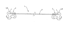
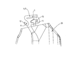
도 1은, 언프레임형(unframed) 광전지 패널의 두 개의 반대편 모서리에 직접적으로 고정되는 장치와 제 1 실시예에 따른 부착하는 장치의 단면도를 도시한다.
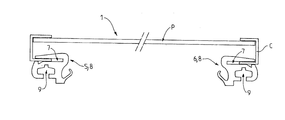
도 2는 프레임형(framed) 광전지 패널의 프레임에 고정되는 장치와 제 2 실시예에 따른 부착하는 장치의 단면도를 도시한다.
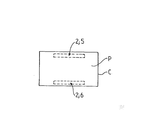
도 2a는 부착하는 장치를 투명하게 볼 수 있는 광전지 패널의 상면도이다.
도 3은 탄성 물질(elastomeric material)로 만들어진 프로파일(profile) 형태로 유지하기 위한 요소의 사시도이다.
도 4는, 비-제한적인 실시예에 따라, 지지대 상에 도 3의 프로파일을 끼어 넣어 부착하는 것을 도시하는 사시도이다.
도 5는 도 4의 단면도이다.
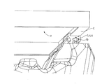
도 6은 광전지 패널의 프레임과 도 5의 프로파일의 결합을 도시한다.
도 7은 본 발명에 따른 장치들의 중재(intermediary)에 의해 태양열 발전 설비 상에 광전지 패널의 부착한 것을 도시한다.
도 8은 고정된 공간(spacing)을 가진 리브(rib) 에 다른 크기들의 광전지 패널을 부착하기 위해서 변형될 수 있는 좀 더 특별한 치수(△) 및 본 발명에 따른 장치의 프로파일의 단면도를 도시한다.
도 9는 본 발명에 따른 부착하는 장치의 제 2 실시예를 도시한다.
도 10 및 도 11은 도 9의 장치와 패널의 부착을 자세히 도시한다.
도 12는 도 9에 따른 장치와 함께 광전지 패널의 유지를 도시하는 단면도이다.BRIEF DESCRIPTION OF THE DRAWINGS The invention may be better understood from the following detailed description taken in conjunction with the accompanying drawings, in which: FIG.
BRIEF DESCRIPTION OF THE DRAWINGS Figure 1 shows a cross-sectional view of a device directly attached to two opposing edges of an unframed photovoltaic panel and an attachment device according to the first embodiment.
Figure 2 shows a cross-sectional view of an apparatus fixed to a frame of a framed photovoltaic panel and an apparatus for attaching according to a second embodiment.
2A is a top view of a photovoltaic panel that can transparently view an attachment device.
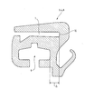
3 is a perspective view of an element for retaining in the form of a profile made of an elastomeric material.
FIG. 4 is a perspective view illustrating fitting of the profile of FIG. 3 onto a support in accordance with a non-limiting embodiment.
5 is a cross-sectional view of Fig.
Figure 6 shows the combination of the frame of Figure 5 with the frame of the photovoltaic panel.
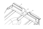
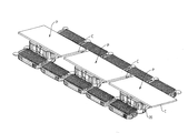
Figure 7 shows the attachment of a photovoltaic panel on a solar thermal power plant by the intermediaries of the devices according to the invention.
Figure 8 shows a more particular dimension (DELTA) that can be modified to attach photovoltaic panels of different sizes to a rib with a fixed spacing and a cross-sectional view of the profile of the device according to the invention.
Figure 9 shows a second embodiment of an attachment device according to the invention.
Figures 10 and 11 detail the attachment of the device and panel of Figure 9.
12 is a sectional view showing the maintenance of the photovoltaic panel together with the apparatus according to Fig.
본 발명은 프레임형(framed) 또는 언프레임형(unframed) 광전지 패널을 부착하는 장치(1)에 관한 것이며, 상기 장치(1)는 상기 광전지 패널(P)의 두 평행한 모서리와 결합함으로써(즉, 도 1), 또는 대안적으로 광전지 패널(P)의 프레임의 두 개의 평행한 윙(wing)과 결합함으로써(즉, 도 2 또는 도 12), 광전지 패널(P)을 유지할 수 있는 유지 수단(2)을 포함한다.The present invention relates to a device (1) for attaching a framed or unframed photovoltaic panel, said device (1) comprising at least two pairs of (Fig. 2 or 12), or alternatively by combining with two parallel wings of a frame of the photovoltaic panel P (i.e., Fig. 2 or 12) 2).
본 발명에 따르면, 유지 수단(2)는 요소들(3, 4; 5, 6; 5`, 6`)을 포함하며, 특히 광전지 패널(P)의 프레임(C)의 두 개의 평행한 윙 또는 광전지 패널의 두 개의 평행한 모서리와 결합하는 합성 제품(synthetic)을 포함한다.According to the invention, the holding means 2 comprises
합성 제품(synthetic) 물질로 구성될 때, 상기 요소들 각각은 엘라스토머(elastomer) 같은 단일 플라스틱의 압출 또는 몰딩(moulding)에 의해서, 또는 오버-몰딩(over-moulding) 또는 공압출(coextrusion)의 기술들에 의해 몇몇 플라스틱에 의해서 획득될 수 있다.When constructed from synthetic materials, each of these elements may be formed by extrusion or molding of a single plastic such as an elastomer, or by overmoulding or coextrusion techniques Can be obtained by some plastics.
각 요소는 프레임형 광전지 패널(P)의 프레임(C)의 윙(즉 도 2 또는 도 12)을 수용하도록 설계된 슬롯(7)을 구비하거나, 대안적으로 언프레임형 광전지 패널(P)의 모서리(즉, 도1)를 수용하도록 설계된 슬롯(7)을 구비한다.Each element has a
유지하기 위한 요소들(3, 4; 5, 6; 5`, 6`)에 광전지 패널(P)의 부착은 유지 수단(2)의 슬롯들(7) 안으로 광전지 패널(또는 광전지 패널의 프레임)을 삽입함으로써 장비들 없이 달성될 수 있다.Attachment of the photovoltaic panel P to the
이점적으로는, 상기 요소들(3, 4; 5, 6; 5`, 6`)의 슬롯들(7)은 광전지 패널(P)의 수직 방향, 및 광전지 패널(P)의 평면에 평행한 방향 및 슬롯들(7)의 축에 수직한 방향을 따라 적어도 광전지 패널을 블록킹(blocking)하기 위해 제공된다.Advantageously, the
청구되지 않은 실시예에 따르면, 제 3 방향, 즉 슬롯들(7)의 축을 따라 패널의 블록킹은 상기 요소들과 분리된 블록킹 수단(blocking means)의 중재에 의해서 달성될 수 있다.According to a non-claimed embodiment, blocking of the panel along a third direction, i.e. along the axis of the
도시된 발명에 따르면, 요소들(3, 4; 5, 6; 5`, 6`) 각각은 탄성 클램핑(elastic clamping)의 만들어짐, 및 한편의 상기 요소들(3, 4; 5, 6; 5`, 6`)의 엘라스토머 물질과 다른 한편의 언프레임형 광전지 패널(P) 또는 프레임형 광전지 패널(P)의 프레임(C) 사이의 마찰 때문에 홀로 구비된 슬롯들(7)의 축을 따라 광전지 패널(P)을 블록킹하며, 적어도 슬롯(7)에, 탄성물질로 만들어진다.Each of the
바람직하게는, 유지 수단(2)의 슬롯들(7)은 광전지 패널(P)에 평행하고 동일한 평면에 제한된다.Preferably, the
도 1에 도시된 실시예에 따르면, 요소들(3, 4)의 슬롯들(7)은, 광전지 패널(P)의 두 개의 평행한 모서리 상에 언프레임형 광전지 패널을 유지하기 위해서, 안쪽으로, 서로 마주볼 수 있다.According to the embodiment shown in Figure 1, the
도 2 또는 도 12에 도시된 다른 실시예에 따르면, 요소들(5, 6; 5`, 6`)의 슬롯들(7)은 프레임(C)의 두 개의 평행한 윙(wing)에 프레임형 광전지 패널의 프레임(C)을 유지하기 위해서 바깥쪽으로 돌려진다.2 or 12, the
보다 구체적으로, 상기된 후자의 실시예에 따르면, 패널의 프레임은 합성 제품 요소들(5, 6;5`, 6`)의 슬롯들(7)에 의해 유지될 수 있으며 패널 아래에 배치되는 돌출된 윙을 포함한다.More specifically, according to the latter embodiment described above, the frame of the panel can be held by the
이점적으로, 도 2 또는 도 12에 도시된 것처럼, 이러한 위치에서는, 요소들(5, 6)은 자외선 복사 및 궂은 날씨로부터 상기 요소들을 보호하기 위해서, 광전지 패널(P) 및 광전지 패널의 프레임(C)에 의해 적어도 부분적으로 덮여있다.Advantageously, in this position, as shown in FIG. 2 or 12, the
비-제한적인 실시예에 따르면, 적어도 하나의 요소 또는 요소들(3, 4; 5, 6) 각각은 합성 제품 프로파일(profile)(8) 형태를 취하며, 유지를 위한 상기 요소들의 슬롯(7)은 상기 프로파일(8)에 세로 방향에 있다. 유리하게는, 이러한 프로파일(8)은 몇몇 플라스틱의 공압출 또는 플라스틱의 압출에 의해서 얻어질 수 있다. 예컨대, 합성 제품 요소들의 플라스틱은 ExxonMobil 회사 또는 다른 상업회사의 SantopreneTM 같은 열가소성 엘라스토머일 수 있다.According to a non-limiting embodiment, each of at least one element or
보다 구체적으로, 서로 평행한 두 개의 프로파일(8)은 언프레임형 광전지 패널(P)의 두 개의 평행한 모서리, 또는 대안적으로 프레임형 광전지 패널의 프레임의 두 개의 평행한 윙을 유지하도록 할 수 있다.More specifically, two
요소의 고정을 쉽게 하기 위해서, 특히 합성 제품, 합성 제품 지지대 상에서, 상기 또는 각각의 합성 제품 요소들(3, 4; 5, 6)은 상기 세로 방향의 슬롯(7)뿐만 아니라 상보 리브(complementary rib)(10)를 구비하는 지지대에 합성 제품 요소의 부착을 허용하는 고정 홈(fixing groove)(9)을 포함할 수 있다.In order to facilitate fixing of the elements, in particular on the synthetic product, the synthetic product support, the or each of the or each of the
상기 실시예에 따르면, 지지대 상에 상기 요소(8)의 고정은, 상기 합성 제품 요소(3, 4; 5, 6) 특히 프로파일(9)의 상기 홈(9) 안으로 지지대의 상보 리브(10)를 간단하게 삽입하여, 특별한 도구 없이 이루어진다. 일단 제자리에 위치되면, 리브의 방향에 따른 상기 합성 제품 요소의 유지(maintaining)는 상기 요소의 합성 제품 물질, 특히 엘라스토머 및 상보 리브(10)의 물질, 특히 플라스틱 사이의 마찰력 때문에 쉽게 달성될 수 있다.According to this embodiment, the fixing of the
고정 홈(9)은 열쇠구멍 형태(프래피즈(trapeze)와 결합된 디스크) 또는 상보 리브(10)로부터 상기 합성 제품 요소(3, 4;5, 6)를 당김으로써 제거되는 것을 방지하는 다른 형태의 T형 구역을 구비할 수 있다.The locking
바람직하게는, 고정 홈(9)의 축은 슬롯(7)의 축에 평행하다. 상기 요소(3, 4;5, 6)가 합성 제품 프로파일(8)인 경우, 플롯(7) 및 고정 홈(9)은 동일한 압출 단계 동안에 얻어진다.Preferably, the axis of the fixing
도시된 실시예에 따르면, 지지대(20)는, 광전지 패널의 고정하는 치수에 상응하는 치수로 서로 평행하고 서로 분리되어 두 개의 리브(10)가 구비된 상부면 상에, 하나의 요소, 특히 플라스틱, 특히 단일부의 형태를 취할 수 있다.According to the illustrated embodiment, the
통상적으로, 두 개의 상보 리브(10) 사이에 공간은 고정된다. 하지만, 다양한 크기의 패널이 적합한 합성 제품 요소, 특히 적합한 프로파일(8)을 선택함으로써 이러한 두 개의 리브(10)에 부착될 수 있다.Typically, the space between the two
보다 구체적으로, 슬롯(7)의 하부(70) 및 고정 홈(9) 사이에 정의된, 도 8에 도시된 치수(dimension)(△)에 작용함으로써, 최소의 비용으로 다양한 크기의 패널에 적응하는 것과 같이, 특히 패널(또는 패널의 프레임)의 두 개의 모서리에 고정을 유지하도록 설계된 두 개의 슬롯(7)의 하부(70) 사이의 공간이 조절 가능하다. 상기 요소 특히 합성 제품이 프로파일(8)이거나 분리된 치수들(△)을 구비하는 몇몇의 프로파일을 얻기 위한 생산 장비의 비싸지 않은 조각들인 복수의 압출 금형(extrusion dies)을 구비하기 위해서 프로파일(85)을 포함할 때, 상기 변화들이 요구된다.More specifically, by acting on the dimension (DELTA) shown in FIG. 8 defined between the
실시예에 따르면, 합성 제품 물질로 만들어진 프로파일(8)은, 특히 슬롯(7)의 반대편 상에, 전기 케이블이 지나가도록 설계된 홈(11)을 구비할 수 있으며, 상기 홈은 유지하기 위한 요소(3, 4, 5, 6)의 몸체(81) 및 상기 유지하기 위한 요소의 신축성 윙(flexible wing)(12) 사이에 형성된다.According to an embodiment, the
보다 구체적으로, 도 3에 도시된 것처럼, 상기 합성 제품 물질로 만들어진 프로파일(8)은, 프로파일에 세로 방향인, 광전지 패널 또는 광전지 패널의 프레임(C)의 유지를 위해 설계된 상기 슬롯(7)을 포함한다. 상기 슬롯(7)은 상부 윙(80) 특히 프로파일(8)의 고무 밴드(elastic) 및 프로파일(8)의 몸체(81) 사이에 정의되며, 상부 윙(80) 및 몸체(81)는 프로파일(8)의 정션부(junction portion)(82)에 의해서 상부 윙 및 몸체 사이에 붙어 있다.More specifically, as shown in FIG. 3, the
상기 슬롯(7)은 상부 윙(80), 고무 밴드 및 몸체(81) 사이에 들어온 광전지 패널(P) 또는 광전지 패널의 프레임(C)를 유지하는 것을 가능하게 한다. 상기 프로파일(8)은 패널을 제거하는 방향으로 마찰력을 증가하도록 설계된 돌림 방지 기능을 가진 투스(tooth)(84)를 슬롯(7)의 개구(opening)(83)에 구비할 수 있다. 상기 투스(84)는 특히 슬롯(7)의 하부 벽 상에서 몸체(81) 깊게, 삼각형의 홈(85)에 의해서 구체화된다.The
도 3에 도시되었듯이,프로파일(8)은, 상보 구역의 리브(10)에 프로파일을 끼워 넣어 부착하도록 설계된 프로파일(8)의 하단부 아래에서 열리면서, 특히 T형 구역을 가진, 고정 홈(9)을 또한 구비할 수 있다. 프로파일은 상기 프로파일의 몸체(81) 및 신축성 윙(12) 사이에 형성된, 상기 슬롯(7) 반대편 상에, 프로파일의 길이 방향으로, 케이블이 통과하는 기능을 가진 홈(11)을 추가로 구비할 수 있다.3, the
유리하게는, 본 발명에 따르면, 유지 수단은 광전지 패널(P)의 두 개의 반대편 모서리(또는 프레임형 광전지 패널의 프레임(c)의 두 개의 평행한 윙)와 유일하게 결합하며, 상기 방식으로 광전지 패널은 도 6에서 비-제한적인 예에 따라 도시된 것과 같은 상기 슬롯에 평행한 방향으로 유지 수단(2)(즉, 요소(3, 4; 5, 6;5`, 6`)를 넘어 연장하면서 구비될 수 있다.Advantageously, according to the invention, the holding means is uniquely associated with two opposite edges of the photovoltaic panel (or two parallel wings of the frame (c) of the frame-type photovoltaic panel) The panel extends beyond the holding means 2 (i.e.,
엄밀한 의미에서, 유지된 모서리 방향의 광전지 패널의 치수는 설치 제한이 아니다.In the strict sense, the dimension of the photovoltaic panel in the maintained corner direction is not an installation limitation.
이점적으로는, 광전지 패널의 고정된 모서리들에 수직하고 광전지 패널에 평행한 방향에 따라, 유지하기 위한 요소들(3, 4; 5, 6; 5`, 6`)의 슬롯(7)의 깊이는 과다할 수 있다.Advantageously, it is possible to maintain the position of the
상기 증착은 확장 현성 때문에 패널 및/또는 지지대의 치수의 변화를 고려하는 것을 가능하게 하며, 패널(패널의 프레임)이 두 개의 슬롯(7)의 하부(70)에 인접하는 것을 방지한다.The deposition makes it possible to take into account the variation of the dimensions of the panel and / or the support due to the expansion stiffness and to prevent the panel (the frame of the panel) from adjoining the
도 9 내지 12에 도시된 실시예에 따르면, 상기 또는 각각의 요소(5` 또는 6`)는 프로파일(85) 또는 엘라스토머 스트립(elastomeric strip)(86)을 포함하며, 상기 프로파일(85)은 엘라스토머 스트립(86)을 수용하고 측면으로 개방하는 채널(87)을 구비하며, 상기 채널(87)은 상기 요소의 슬롯(7)을 구성하는 상기 엘라스토머 스트립(86)과 구비된다.9-12, the or each element (5 'or 6') comprises a
프로파일(85)은 금속, 예컨대 알루미늄 이나 다른 물질로 만들어질 수 있다. 프로파일(85)의 채널(87)은 정션 윙(junction wing)(89)에 의해 프로파일(85)의 몸체에 인접하는 프로파일의 상부 윙(88) 사이에 정의된다.The
프로파일(85)은 또한, 상보 구역의 리브(10)에 프로파일을 끼워 넣어 부착하도록 설계된 프로파일(85)의 하단부 아래에서 열리는 T형 구역을 가진 고정 홈(9)을 구비한다. 프로파일은 또한 프로파일(85)의 몸체 및 윙(12`) 사이에 형성된, 상기 슬롯(7) 반대편 상에, 프로파일의 측면으로, 케이블이 통과하는 기능을 지닌 홈(11)을 구비할 수 있다The
설치 동안에, 프레임형 광전지 패널은 다음의 단계에 따라 지지대 상에 고정될 수 있다.During installation, the frame-type photovoltaic panel can be fixed on the support by the following steps.
- 지지대 상에 요소들의 프로파일(85)의 고정 및 상기 요소들(5`, 6`)의 프로파일(85)의 채널(87) 안에 광전지 패널(P)의 프레임(C)의 두 개의 평행한 윙을 제 위치에 설치하는 단계; 및Of the frame (C) of the photovoltaic panel (P) in the channel (87) of the profile (85) of the elements (5 ', 6' In place; And
- 채널(87) 안으로 엘라스토머 스트립들(86)의 강제적인 삽입을 통하여 채널(87)에서 광전지 패널(P)을 블록킹하는 단계.Blocking the photovoltaic panel (P) in the channel (87) through the forced insertion of the elastomeric strips (86) into the channel (87).
지지대에 프로파일(85)의 고정은 프로파일의 고정 홈(9) 안으로 지지대의 고정 리브를 삽입함으로써 수행될 수 있다. 가능하게는 고정 나사가 프로파일 및 리브를 동시에 통과하는 나사와 함께 리브의 축을 따라 프로파일의 위치를 블록킹하는데 사용될 수 있다.The fixing of the
채널(87)에 엘라스토머 스트립(86)을 삽입하는 단계는 드라이버 같은 공구로 사람 손으로 수행될 수 있다.The step of inserting the
일단 삽입된 엘라스토머 스트립(86)은 프로파일(85)의 채널(87)의 내부 벽과 엘라스토머 스트립 표면들의 일부 및 광전지 패널(P)의 프레임의 윙과 엘라스토머 스트립 표면들의 다른 일부를 통하여 접촉한다. 엘라스토머 스트립(86)은 만들어진 마찰력 때문에 슬롯들(7)의 축을 따라 패널의 블록킹을 제공한다.Once inserted, the
본 발명에 따른 장치는 지지대, 지붕, 발전선, 등에 광전지 패널을 부착할 필요성이 있을 때 기술적 해결책을 제시한다.The device according to the invention presents a technical solution when there is a need to attach a photovoltaic panel to a support, a roof, a power line, and the like.
또한 본 발명은 본 발명에 따른 부착하는 장치 및 광전지 패널을 포함하는 유닛유 관한 것이며, 상기 장치는 광전지 패널의 유지를 제공한다.The present invention also relates to an apparatus for attaching and a unit comprising a photovoltaic panel according to the invention, the apparatus providing for the maintenance of a photovoltaic panel.
예컨대, 도 3에 도시된 실시예에 따르면, 요소들은 합성 제품, 및 보다 구체적으로는 엘라스토머 물질로 만들어진 단일부의 프로파일이다.For example, according to the embodiment shown in FIG. 3, the elements are synthetic products, and more specifically, a profile of a single portion made of an elastomeric material.
다른 실시예들은 이하의 청구항에 정의된 발명의 범위를 떠나지 않는 한 통상의 기술자에게 자명할 것이다.Other embodiments will be apparent to those of ordinary skill in the art without departing from the scope of the invention as defined in the following claims.
1: 부착하는 장치(Device for attaching),
2: 유지 수단(Means for maintaining),
3, 4, 5, 6: 합성 제품 요소(Synthetic elements),
5', 6': 요소(Elements),
7: 슬롯(Slot),
8: 프로파일(Profile),
9: 고정 홈(Fixing groove),
10: 상보 리브(Complementary rib) (고정 홈(9)),
11: 케이블 통과 홈(Cable passing groove),
12: 신축성 윙(Flexible wing)(홈(11) 프로파일(8)),
12: 윙(Wing) (홈(11) profile(85)),
20: 지지대(Support),
70: 하부(Bottom) (슬롯(7)),
80: 상부 윙(Upper wing) (프로파일(8)),
81: 몸체(Body) (프로파일(8)),
82: 정션부(Junction portion),
83: 개구(Opening),
84: 투스(Tooth),
85: 프로파일(Profile),
86: 엘라스토머 스트립(Elastomeric strip),
87: 채널(Channel) (프로파일(85)),
88: 상부 윙(Upper wing) (프로파일(85)),
89: 정션 윙(Junction wing) (프로파일(85)),
P: 광전지 패널(Photovoltaic panel),
C: 프레임(Frame) (광전지 패널).1: Device for attaching,
2: Means for maintaining,
3, 4, 5, 6: Synthetic elements,
5 ', 6': Elements,
7: Slot,
8: Profile,
9: Fixing groove,
10: Complementary ribs (fixing grooves 9),
11: Cable passing groove,
12: Flexible wing (groove (11) profile (8)),
12: Wing (groove (11) profile (85)),
20: Support,
70: Bottom (slot 7),
80: Upper wing (profile 8),
81: Body (profile 8),
82: Junction portion,
83: Opening,
84: Tooth,
85: Profile,
86: Elastomeric strip,
87: Channel (profile 85),
88: Upper wing (profile 85),
89: Junction wing (profile 85),
P: Photovoltaic panel,
C: Frame (photovoltaic panel).
Claims (15)
상기 유지 수단(2)은 상기 광전지 패널(P)의 두 개의 평행한 모서리 또는 광전지 패널(P)의 프레임의 평행한 윙을 결합하는 요소들(3, 4; 5, 6; 5`, 6`)을 포함하며,
상기 요소들 각각은 프레임형 광전지 패널(P)의 프레임의 윙을 수용하도록 설계되거나 언프레임형 광전지 패널(P)의 모서리를 수용하도록 설계된 슬롯(7)을 구비하여, 슬롯(7)의 축에 수직하고 광전지 패널(P)의 평면에 평행한 방향 및 광전지 패널(P)에 수직 방향을 따라 적어도 광전지 패널의 블록킹을 제공하며,
상기 요소들(3, 4; 5, 6; 5`, 6`)은, 엘라스토머로 각각 만들어지며, 탄성 클램핑(elastic clamping)의 형성 및 한편의 상기 요소들(3, 4; 5, 6; 5`, 6`)의 엘라스토머 물질과 다른 한편의 언프레임형 광전지 패널(P) 또는 프레임형 광전지 패널(P) 사이의 마찰력으로 인하여, 적어도 슬롯(7) 상에서, 유일하게 요소들의 슬롯(7)의 축을 따라 광전지 패널(P)을 블록킹(blocking)하며,
상기 유지 수단은 광전지 패널의 프레임의 두 개의 윙 또는 광전지 패널(P)의 두 개의 반대편 모서리와 홀로 결합하는 방식 및 광전지 패널이 슬롯(7)의 축을 따라 상기 유지기 위한 수단을 넘어 연장하여 구비될 수 있는 방식으로 배치되는 광전지 패널을 부착하는 장치.Frame type or unframe type photovoltaic panel comprising holding means (2) capable of holding a photovoltaic panel by combining two parallel edges of the photovoltaic panel (P) or two parallel wings of the frame of the photovoltaic panel (P) 1. A device (1) for attaching,
The holding means 2 comprises two parallel edges of the photovoltaic panel P or elements 3, 4; 5, 6; 5 ', 6` for joining the parallel wings of the frame of the photovoltaic panel P. [ ),
Each of the elements has a slot 7 designed to accommodate the wings of the frame of the frame-type photovoltaic panel P or to accommodate the corners of the unframed photovoltaic panel P, Providing at least a blocking of the photovoltaic panel along a direction perpendicular to the plane of the photovoltaic panel (P) and a direction parallel to the plane of the photovoltaic panel (P)
The elements (3, 4; 5, 6; 5 ', 6') are each made of an elastomer and the formation of elastic clamping, Due to the frictional force between the elastomeric material of the frame 7 and the frame type photovoltaic panel P or the unframed photovoltaic panel P or frame type photovoltaic panel P of the other, Blocking the photovoltaic panel P along the axis,
The holding means may comprise two wings of the frame of the photovoltaic panel or a combination of two opposite edges of the photovoltaic panel (P) with one another and a photovoltaic panel extending along the axis of the slot (7) Gt; A < / RTI > apparatus for attaching a photovoltaic panel as claimed in any preceding claim.
요소들(3, 4; 5, 6) 각각은 상기 슬롯(7)뿐 아니라 상기 고정 홈(9) 안으로 삽입되도록 설계된 상보 리브(10)를 구비하는 지지대에 합성 제품 요소를 부착하게 할 수 있는 고정 홈(9)을 포함하는 광전지 패널을 부착하는 장치.The method according to claim 1,
Each of the elements 3, 4; 5, 6 is fastened to the support 7 with a complementary rib 10 designed to be inserted into the slot 7, A device for attaching a photovoltaic panel comprising a groove (9).
슬롯(7)의 축 및 고정 홈(9)의 축은 서로 평행한 광전지 패널을 부착하는 장치.3. The method of claim 2,
Wherein the axis of the slot (7) and the axis of the fixing groove (9) attach the photovoltaic panels parallel to each other.
고정 홈은 T형 구역을 구비하는 광전지 패널을 부착하는 장치.The method according to claim 2 or 3,
Wherein the securing groove has a T-shaped section.
요소들(3, 4)의 슬롯들(7)은 광전지 패널(P)의 두 개의 평행한 모서리 상에 언프레임형 광전지 패널을 유지시키기 위해서, 안쪽으로 서로 직면하는 광전지 패널을 부착하는 장치.5. The method according to any one of claims 1 to 4,
Wherein the slots (7) of the elements (3,4) attach the photovoltaic panels facing inwardly to hold the unframed photovoltaic panel on two parallel edges of the photovoltaic panel (P).
요소들(5, 6; 5`, 6`)의 슬롯(7)은 프레임(C)의 두 개의 평행한 윙에 프레임형 광전지 패널의 프레임을 유지시키기 위해서 바깥쪽으로 돌려진 광전지 패널을 부착하는 장치.5. The method according to any one of claims 1 to 4,
The slots 7 of the elements 5, 6; 5 ', 6 ' are arranged in two parallel wings of the frame C, with a device for attaching photovoltaic panels turned outwardly to hold the frame of the frame- .
적어도 하나의 요소(3, 4; 5, 6) 또는 요소 각각은 합성 제품 프로파일(8)의 형태를 가지며,
유지하기 위한 요소의 슬롯(7)은 프로파일(8)에 길이 방향으로 있는 광전지 패널을 부착하는 장치.7. The method according to any one of claims 1 to 6,
Each of the at least one element (3, 4; 5, 6) or element has the form of a composite product profile (8)
A slot (7) of an element for holding a photovoltaic panel in longitudinal direction in a profile (8).
프로파일(8)은, 슬롯(7)의 반대편 상에, 상기 합성 제품 요소의 신축성 윙(12) 및 유지하기 위한 요소(3, 4; 5,6)의 몸체 사이에 형성된 케이블의 통과를 위해 설계된 홈(11)을 구비하는 광전지 패널을 부착하는 장치.8. The method of claim 7,
The profile 8 is designed on the opposite side of the slot 7 for the passage of cables formed between the body of the elastic wings 12 of the composite product element and the elements 3, A device for attaching a photovoltaic panel comprising a groove (11).
상기 요소 또는 요소 각각은 엘라스토머로 만들어진 단일부의 프로파일(8)의 형태를 가지는 광전지 패널을 부착하는 장치.9. The method according to claim 7 or 8,
Each of said elements or elements having the form of a profile (8) of an end portion made of an elastomer.
상기 요소들(3, 4; 5, 6)은 합성 제품 요소인 프레임형 또는 언프레임형 광전지 패널을 부착하는 장치.10. The method according to any one of claims 1 to 9,
The element (3, 4; 5, 6) is a composite product element that attaches to a frame or unframe photovoltaic panel.
상기 요소(5`, 6) 또는 요소 각각은 특히 금속으로 만들어진 프로파일(85) 및 엘라스토머 스트립(86)을 포함하며,
상기 프로파일(85)은, 측면에서 열려 엘라스토머 스트립(86)을 수용하는 채널(87)을 구비하며,
상기 채널(87)은 상기 요소(5`, 6`)의 슬롯(7)을 구성하는 엘라스토머 스트립(86)을 구비하는 광전지 패널을 부착하는 장치.7. The method according to any one of claims 1 to 6,
Each of said elements (5 ', 6) or elements comprises a profile (85) and an elastomeric strip (86), in particular made of metal,
The profile 85 has a channel 87 that opens at the side and receives the elastomeric strip 86,
Wherein the channel (87) comprises an elastomeric strip (86) constituting a slot (7) of the element (5 ', 6').
프로파일(85)은, 슬롯(7)의 반대편에, 상기 프로파일의 윙(12) 및 유지하기 위한 요소의 몸체 사이에 형성된 케이블의 통과를 위해 설계된 홈(11)이 구비되는 광전지 패널을 부착하는 장치.12. The method of claim 11,
The profile 85 is a device for attaching a photovoltaic panel with a groove 11 designed for passage of a cable formed between the wing 12 of the profile and the body of the element for holding, .
채널(87) 안으로 엘라스토머 스트립들(86)의 강제적인 삽입을 통하여 채널(87)에서 광전지 패널(P)을 블록킹하는 단계;
를 포함하는 제 11 항 또는 제 12 항에 따른 부착하는 장치에 의해 설치된 지지대 상에 광전지 패널을 설치하는 방법.The two parallel wings of the frame C of the photovoltaic panel P in the channels 87 of the profiles 85 of the elements 5 ', 6' Installing in place; And
Blocking the photovoltaic panel (P) in the channel (87) through the forced insertion of the elastomeric strips (86) into the channel (87);
Wherein the photovoltaic panel is mounted on a support bracket provided by an attachment device according to claim 11 or 12.
Applications Claiming Priority (3)
| Application Number | Priority Date | Filing Date | Title |
|---|---|---|---|
| FR1253252A FR2989154A1 (en) | 2012-04-10 | 2012-04-10 | METHOD FOR FIXING A PHOTOVOLTAIC PANEL |
| FR1253252 | 2012-04-10 | ||
| PCT/FR2013/050779 WO2013153329A1 (en) | 2012-04-10 | 2013-04-10 | Method for attaching a photovoltaic panel |
Publications (1)
| Publication Number | Publication Date |
|---|---|
| KR20150044423A true KR20150044423A (en) | 2015-04-24 |
Family
ID=48366315
Family Applications (1)
| Application Number | Title | Priority Date | Filing Date |
|---|---|---|---|
| KR1020147028494A KR20150044423A (en) | 2012-04-10 | 2013-04-10 | Method for attaching a photovoltaic panel |
Country Status (9)
| Country | Link |
|---|---|
| US (1) | US9314904B2 (en) |
| EP (1) | EP2836771A1 (en) |
| JP (1) | JP2015520306A (en) |
| KR (1) | KR20150044423A (en) |
| CN (1) | CN104380008B (en) |
| FR (1) | FR2989154A1 (en) |
| HK (1) | HK1201910A1 (en) |
| IN (1) | IN2014DN08346A (en) |
| WO (1) | WO2013153329A1 (en) |
Families Citing this family (15)
| Publication number | Priority date | Publication date | Assignee | Title |
|---|---|---|---|---|
| US8776454B2 (en) * | 2011-04-05 | 2014-07-15 | Michael Zuritis | Solar array support structure, mounting rail and method of installation thereof |
| FR3014830B1 (en) | 2013-12-16 | 2017-02-17 | Ciel Et Terre Int | FLOATING DEVICE PHOTOVOLTAIC PANEL SUPPORT |
| US10171027B2 (en) * | 2015-03-02 | 2019-01-01 | Sunpower Corporation | Photovoltaic module mount |
| US10240820B2 (en) * | 2015-03-25 | 2019-03-26 | Ironridge, Inc. | Clamp for securing and electrically bonding solar panels to a rail support |
| CN106357206A (en) * | 2015-07-17 | 2017-01-25 | 汉能新材料科技有限公司 | Photovoltaic module carrier and matrix |
| US11817818B2 (en) | 2015-07-24 | 2023-11-14 | Tecsi Solar, Inc. | Module frame with cable management flange |
| WO2017019433A1 (en) * | 2015-07-24 | 2017-02-02 | Sunedison, Inc. | Ergonomic solar module frame with cable management flange |
| CN205545095U (en) * | 2016-04-07 | 2016-08-31 | 北京铂阳顶荣光伏科技有限公司 | Solar cell flexible installation structure and agriculture optical filtering sunshade power generation system |
| US9729101B1 (en) | 2016-04-25 | 2017-08-08 | X Development Llc | Deployment techniques of a floating photovoltaic power generation system |
| CN107453689B (en) * | 2016-05-10 | 2023-09-26 | 宿州诺亚坚舟光伏科技有限公司 | Modular floating type photovoltaic array |
| KR101704588B1 (en) * | 2016-05-19 | 2017-02-08 | 주식회사 이엠테크 | Solar frames and railing installation structure provided for this module |
| CA3027978A1 (en) * | 2016-06-17 | 2017-12-21 | PowerField Energy LLC | Solar module mounting and support system |
| US10079569B1 (en) * | 2017-06-16 | 2018-09-18 | Bluescope Buildings North America, Inc. | Roof system for production of electrical power |
| JP2019031896A (en) * | 2017-08-04 | 2019-02-28 | ベイジン アポロ ディン ロン ソーラー テクノロジー カンパニー リミテッド | Groove type mounting bracket, solar power generation unit and mounting method of solar power generation module |
| US11757400B1 (en) | 2023-03-15 | 2023-09-12 | Sunmodo Corporation | Devices for mounting solar PV panels to roofs and other mounting structures |
Family Cites Families (13)
| Publication number | Priority date | Publication date | Assignee | Title |
|---|---|---|---|---|
| US6111189A (en) * | 1998-07-28 | 2000-08-29 | Bp Solarex | Photovoltaic module framing system with integral electrical raceways |
| DE19934073B4 (en) * | 1999-07-19 | 2005-08-25 | Regen Energiesysteme Gmbh | Device for fixing solar modules |
| WO2002041407A1 (en) * | 2000-11-16 | 2002-05-23 | Kaneka Corporation | Solar battery module, photovoltaic power generation system, support block supporting solar battery module, and photovoltaic power generation system installation method |
| AT501455B1 (en) * | 2005-02-21 | 2006-11-15 | Lechthaler Andreas | STRUCTURE FOR PLATE-MADE SOLAR CELL OR SUN COLLECTOR MODULES |
| GB2473966B (en) * | 2008-05-05 | 2013-03-13 | Alden T Gibbs | A system for roofs and the like |
| US20100059641A1 (en) * | 2008-09-10 | 2010-03-11 | Epv Solar, Inc. | Mounting Systems for Photovoltaic Modules |
| US20100089390A1 (en) * | 2008-10-13 | 2010-04-15 | Sunlink, Corp | Solar array mounting system |
| DE102009019548A1 (en) | 2009-04-30 | 2010-11-04 | Wilhelm Ötting Kunststoffverformung GmbH & Co. KG | Assembling module for assembling solar collector at e.g. flat roof of house, has fastening devices displaced at holding rail and fixed in desired position, where holding rails are attached at upper side of columns |
| EP2449599B1 (en) * | 2009-07-02 | 2018-08-15 | SolarCity Corporation | Apparatus for leveling photovoltaic arrays |
| DE202010001518U1 (en) * | 2010-01-28 | 2010-04-22 | Ralos Vertriebs Gmbh | Device for receiving a solar module, in particular photovoltaic module |
| US20110209422A1 (en) * | 2010-02-18 | 2011-09-01 | King Zachary A | Method and apparatus for mounting photovoltaic modules to shingled surfaces |
| US8418983B2 (en) * | 2010-07-29 | 2013-04-16 | First Solar, Inc. | Slider clip and photovoltaic structure mounting system |
| US8590222B2 (en) * | 2010-10-05 | 2013-11-26 | Alexander Koller | Support arrangement |
-
2012
- 2012-04-10 FR FR1253252A patent/FR2989154A1/en active Pending
-
2013
- 2013-04-10 EP EP13721555.4A patent/EP2836771A1/en not_active Withdrawn
- 2013-04-10 WO PCT/FR2013/050779 patent/WO2013153329A1/en active Application Filing
- 2013-04-10 JP JP2015505004A patent/JP2015520306A/en active Pending
- 2013-04-10 US US14/387,564 patent/US9314904B2/en not_active Expired - Fee Related
- 2013-04-10 CN CN201380019237.8A patent/CN104380008B/en active Active
- 2013-04-10 IN IN8346DEN2014 patent/IN2014DN08346A/en unknown
- 2013-04-10 KR KR1020147028494A patent/KR20150044423A/en not_active Application Discontinuation
-
2015
- 2015-03-10 HK HK15102415.6A patent/HK1201910A1/en unknown
Also Published As
| Publication number | Publication date |
|---|---|
| US9314904B2 (en) | 2016-04-19 |
| FR2989154A1 (en) | 2013-10-11 |
| CN104380008A (en) | 2015-02-25 |
| WO2013153329A1 (en) | 2013-10-17 |
| HK1201910A1 (en) | 2015-09-11 |
| JP2015520306A (en) | 2015-07-16 |
| CN104380008B (en) | 2019-05-03 |
| EP2836771A1 (en) | 2015-02-18 |
| IN2014DN08346A (en) | 2015-05-08 |
| US20150075587A1 (en) | 2015-03-19 |
Similar Documents
| Publication | Publication Date | Title |
|---|---|---|
| KR20150044423A (en) | Method for attaching a photovoltaic panel | |
| US20190363668A1 (en) | Panel mounting bracket assembly including an extension device and related methods | |
| US8567154B2 (en) | Apparatus and methods for mounting a photovoltaic module on a roof | |
| US9249995B2 (en) | Solar panel positioning system | |
| RU2630944C2 (en) | Profiled element for vehicle glass connection to cladding component, and profiled element assembly | |
| US20160043688A1 (en) | Solar panel installation systems and methods | |
| CA2850051C (en) | Solar light roof panel abutment structure | |
| US20040221524A1 (en) | Photovoltaic panel mounting bracket | |
| DE202005001469U1 (en) | Roof mounting for solar energy panels is formed from frame produced of extruded section material | |
| CN101903611B (en) | Method for fastening plate or glass panel in frame element and sealing element for use in such method | |
| US9515599B2 (en) | Photovoltaic panel mounting rail with integrated electronics | |
| JP2016185061A (en) | Frame skeleton molding for solar cell laminate, solar module with frame, and coupling system for solar module | |
| US20160017605A1 (en) | Wall panel connecting system for modular building units | |
| JP2018538464A (en) | Profile for tightening glass panels | |
| US20160079909A1 (en) | Photovoltaic panel mounting system | |
| KR101306098B1 (en) | Clamp for solar cell module | |
| ES2908191T3 (en) | Panel mounting bracket with intermediate grounding clamp and related methods | |
| US9948072B2 (en) | Mounting system for arranging electric devices, for example, especially in switchgear cabinets | |
| US20160186487A1 (en) | Method and Fastening Element for Installing a Sunshade in a Glazing Part | |
| WO2015166273A1 (en) | Glazing system for a passenger service vehicle | |
| WO2015116911A1 (en) | Solar module with integrated collapsible rack assembly | |
| US20180026577A1 (en) | Device for attaching a solar panel | |
| EP3243976B1 (en) | Panel splice connector for linear ceiling panels | |
| KR101680612B1 (en) | Glass edge molding structure for curtain wall bracket | |
| DE50000002D1 (en) | Laying profile system for panels |
Legal Events
| Date | Code | Title | Description |
|---|---|---|---|
| WITN | Withdrawal due to no request for examination |