KR20150036184A - Methods and fuel processing apparatuses for upgrading a pyrolysis oil stream and a hydrocarbon stream - Google Patents
Methods and fuel processing apparatuses for upgrading a pyrolysis oil stream and a hydrocarbon stream Download PDFInfo
- Publication number
- KR20150036184A KR20150036184A KR1020157001939A KR20157001939A KR20150036184A KR 20150036184 A KR20150036184 A KR 20150036184A KR 1020157001939 A KR1020157001939 A KR 1020157001939A KR 20157001939 A KR20157001939 A KR 20157001939A KR 20150036184 A KR20150036184 A KR 20150036184A
- Authority
- KR
- South Korea
- Prior art keywords
- pyrolysis oil
- stream
- reaction zone
- oil stream
- hydrocarbon
- Prior art date
Links
Images

Classifications
-
- C—CHEMISTRY; METALLURGY
- C10—PETROLEUM, GAS OR COKE INDUSTRIES; TECHNICAL GASES CONTAINING CARBON MONOXIDE; FUELS; LUBRICANTS; PEAT
- C10G—CRACKING HYDROCARBON OILS; PRODUCTION OF LIQUID HYDROCARBON MIXTURES, e.g. BY DESTRUCTIVE HYDROGENATION, OLIGOMERISATION, POLYMERISATION; RECOVERY OF HYDROCARBON OILS FROM OIL-SHALE, OIL-SAND, OR GASES; REFINING MIXTURES MAINLY CONSISTING OF HYDROCARBONS; REFORMING OF NAPHTHA; MINERAL WAXES
- C10G3/00—Production of liquid hydrocarbon mixtures from oxygen-containing organic materials, e.g. fatty oils, fatty acids
- C10G3/42—Catalytic treatment
-
- C—CHEMISTRY; METALLURGY
- C10—PETROLEUM, GAS OR COKE INDUSTRIES; TECHNICAL GASES CONTAINING CARBON MONOXIDE; FUELS; LUBRICANTS; PEAT
- C10G—CRACKING HYDROCARBON OILS; PRODUCTION OF LIQUID HYDROCARBON MIXTURES, e.g. BY DESTRUCTIVE HYDROGENATION, OLIGOMERISATION, POLYMERISATION; RECOVERY OF HYDROCARBON OILS FROM OIL-SHALE, OIL-SAND, OR GASES; REFINING MIXTURES MAINLY CONSISTING OF HYDROCARBONS; REFORMING OF NAPHTHA; MINERAL WAXES
- C10G11/00—Catalytic cracking, in the absence of hydrogen, of hydrocarbon oils
- C10G11/02—Catalytic cracking, in the absence of hydrogen, of hydrocarbon oils characterised by the catalyst used
-
- B—PERFORMING OPERATIONS; TRANSPORTING
- B01—PHYSICAL OR CHEMICAL PROCESSES OR APPARATUS IN GENERAL
- B01J—CHEMICAL OR PHYSICAL PROCESSES, e.g. CATALYSIS OR COLLOID CHEMISTRY; THEIR RELEVANT APPARATUS
- B01J4/00—Feed or outlet devices; Feed or outlet control devices
- B01J4/001—Feed or outlet devices as such, e.g. feeding tubes
- B01J4/002—Nozzle-type elements
-
- C—CHEMISTRY; METALLURGY
- C10—PETROLEUM, GAS OR COKE INDUSTRIES; TECHNICAL GASES CONTAINING CARBON MONOXIDE; FUELS; LUBRICANTS; PEAT
- C10G—CRACKING HYDROCARBON OILS; PRODUCTION OF LIQUID HYDROCARBON MIXTURES, e.g. BY DESTRUCTIVE HYDROGENATION, OLIGOMERISATION, POLYMERISATION; RECOVERY OF HYDROCARBON OILS FROM OIL-SHALE, OIL-SAND, OR GASES; REFINING MIXTURES MAINLY CONSISTING OF HYDROCARBONS; REFORMING OF NAPHTHA; MINERAL WAXES
- C10G11/00—Catalytic cracking, in the absence of hydrogen, of hydrocarbon oils
- C10G11/14—Catalytic cracking, in the absence of hydrogen, of hydrocarbon oils with preheated moving solid catalysts
- C10G11/18—Catalytic cracking, in the absence of hydrogen, of hydrocarbon oils with preheated moving solid catalysts according to the "fluidised-bed" technique
- C10G11/187—Controlling or regulating
-
- C—CHEMISTRY; METALLURGY
- C10—PETROLEUM, GAS OR COKE INDUSTRIES; TECHNICAL GASES CONTAINING CARBON MONOXIDE; FUELS; LUBRICANTS; PEAT
- C10G—CRACKING HYDROCARBON OILS; PRODUCTION OF LIQUID HYDROCARBON MIXTURES, e.g. BY DESTRUCTIVE HYDROGENATION, OLIGOMERISATION, POLYMERISATION; RECOVERY OF HYDROCARBON OILS FROM OIL-SHALE, OIL-SAND, OR GASES; REFINING MIXTURES MAINLY CONSISTING OF HYDROCARBONS; REFORMING OF NAPHTHA; MINERAL WAXES
- C10G3/00—Production of liquid hydrocarbon mixtures from oxygen-containing organic materials, e.g. fatty oils, fatty acids
- C10G3/50—Production of liquid hydrocarbon mixtures from oxygen-containing organic materials, e.g. fatty oils, fatty acids in the presence of hydrogen, hydrogen donors or hydrogen generating compounds
-
- C—CHEMISTRY; METALLURGY
- C10—PETROLEUM, GAS OR COKE INDUSTRIES; TECHNICAL GASES CONTAINING CARBON MONOXIDE; FUELS; LUBRICANTS; PEAT
- C10G—CRACKING HYDROCARBON OILS; PRODUCTION OF LIQUID HYDROCARBON MIXTURES, e.g. BY DESTRUCTIVE HYDROGENATION, OLIGOMERISATION, POLYMERISATION; RECOVERY OF HYDROCARBON OILS FROM OIL-SHALE, OIL-SAND, OR GASES; REFINING MIXTURES MAINLY CONSISTING OF HYDROCARBONS; REFORMING OF NAPHTHA; MINERAL WAXES
- C10G3/00—Production of liquid hydrocarbon mixtures from oxygen-containing organic materials, e.g. fatty oils, fatty acids
- C10G3/54—Production of liquid hydrocarbon mixtures from oxygen-containing organic materials, e.g. fatty oils, fatty acids characterised by the catalytic bed
- C10G3/55—Production of liquid hydrocarbon mixtures from oxygen-containing organic materials, e.g. fatty oils, fatty acids characterised by the catalytic bed with moving solid particles, e.g. moving beds
- C10G3/57—Production of liquid hydrocarbon mixtures from oxygen-containing organic materials, e.g. fatty oils, fatty acids characterised by the catalytic bed with moving solid particles, e.g. moving beds according to the fluidised bed technique
-
- C—CHEMISTRY; METALLURGY
- C10—PETROLEUM, GAS OR COKE INDUSTRIES; TECHNICAL GASES CONTAINING CARBON MONOXIDE; FUELS; LUBRICANTS; PEAT
- C10G—CRACKING HYDROCARBON OILS; PRODUCTION OF LIQUID HYDROCARBON MIXTURES, e.g. BY DESTRUCTIVE HYDROGENATION, OLIGOMERISATION, POLYMERISATION; RECOVERY OF HYDROCARBON OILS FROM OIL-SHALE, OIL-SAND, OR GASES; REFINING MIXTURES MAINLY CONSISTING OF HYDROCARBONS; REFORMING OF NAPHTHA; MINERAL WAXES
- C10G3/00—Production of liquid hydrocarbon mixtures from oxygen-containing organic materials, e.g. fatty oils, fatty acids
- C10G3/60—Controlling or regulating the processes
-
- C—CHEMISTRY; METALLURGY
- C10—PETROLEUM, GAS OR COKE INDUSTRIES; TECHNICAL GASES CONTAINING CARBON MONOXIDE; FUELS; LUBRICANTS; PEAT
- C10G—CRACKING HYDROCARBON OILS; PRODUCTION OF LIQUID HYDROCARBON MIXTURES, e.g. BY DESTRUCTIVE HYDROGENATION, OLIGOMERISATION, POLYMERISATION; RECOVERY OF HYDROCARBON OILS FROM OIL-SHALE, OIL-SAND, OR GASES; REFINING MIXTURES MAINLY CONSISTING OF HYDROCARBONS; REFORMING OF NAPHTHA; MINERAL WAXES
- C10G51/00—Treatment of hydrocarbon oils, in the absence of hydrogen, by two or more cracking processes only
- C10G51/02—Treatment of hydrocarbon oils, in the absence of hydrogen, by two or more cracking processes only plural serial stages only
- C10G51/04—Treatment of hydrocarbon oils, in the absence of hydrogen, by two or more cracking processes only plural serial stages only including only thermal and catalytic cracking steps
-
- B—PERFORMING OPERATIONS; TRANSPORTING
- B01—PHYSICAL OR CHEMICAL PROCESSES OR APPARATUS IN GENERAL
- B01J—CHEMICAL OR PHYSICAL PROCESSES, e.g. CATALYSIS OR COLLOID CHEMISTRY; THEIR RELEVANT APPARATUS
- B01J2204/00—Aspects relating to feed or outlet devices; Regulating devices for feed or outlet devices
- B01J2204/002—Aspects relating to feed or outlet devices; Regulating devices for feed or outlet devices the feeding side being of particular interest
-
- B—PERFORMING OPERATIONS; TRANSPORTING
- B01—PHYSICAL OR CHEMICAL PROCESSES OR APPARATUS IN GENERAL
- B01J—CHEMICAL OR PHYSICAL PROCESSES, e.g. CATALYSIS OR COLLOID CHEMISTRY; THEIR RELEVANT APPARATUS
- B01J2204/00—Aspects relating to feed or outlet devices; Regulating devices for feed or outlet devices
- B01J2204/007—Aspects relating to the heat-exchange of the feed or outlet devices
-
- C—CHEMISTRY; METALLURGY
- C10—PETROLEUM, GAS OR COKE INDUSTRIES; TECHNICAL GASES CONTAINING CARBON MONOXIDE; FUELS; LUBRICANTS; PEAT
- C10G—CRACKING HYDROCARBON OILS; PRODUCTION OF LIQUID HYDROCARBON MIXTURES, e.g. BY DESTRUCTIVE HYDROGENATION, OLIGOMERISATION, POLYMERISATION; RECOVERY OF HYDROCARBON OILS FROM OIL-SHALE, OIL-SAND, OR GASES; REFINING MIXTURES MAINLY CONSISTING OF HYDROCARBONS; REFORMING OF NAPHTHA; MINERAL WAXES
- C10G2300/00—Aspects relating to hydrocarbon processing covered by groups C10G1/00 - C10G99/00
- C10G2300/10—Feedstock materials
- C10G2300/1011—Biomass
-
- C—CHEMISTRY; METALLURGY
- C10—PETROLEUM, GAS OR COKE INDUSTRIES; TECHNICAL GASES CONTAINING CARBON MONOXIDE; FUELS; LUBRICANTS; PEAT
- C10G—CRACKING HYDROCARBON OILS; PRODUCTION OF LIQUID HYDROCARBON MIXTURES, e.g. BY DESTRUCTIVE HYDROGENATION, OLIGOMERISATION, POLYMERISATION; RECOVERY OF HYDROCARBON OILS FROM OIL-SHALE, OIL-SAND, OR GASES; REFINING MIXTURES MAINLY CONSISTING OF HYDROCARBONS; REFORMING OF NAPHTHA; MINERAL WAXES
- C10G2300/00—Aspects relating to hydrocarbon processing covered by groups C10G1/00 - C10G99/00
- C10G2300/10—Feedstock materials
- C10G2300/1074—Vacuum distillates
-
- C—CHEMISTRY; METALLURGY
- C10—PETROLEUM, GAS OR COKE INDUSTRIES; TECHNICAL GASES CONTAINING CARBON MONOXIDE; FUELS; LUBRICANTS; PEAT
- C10G—CRACKING HYDROCARBON OILS; PRODUCTION OF LIQUID HYDROCARBON MIXTURES, e.g. BY DESTRUCTIVE HYDROGENATION, OLIGOMERISATION, POLYMERISATION; RECOVERY OF HYDROCARBON OILS FROM OIL-SHALE, OIL-SAND, OR GASES; REFINING MIXTURES MAINLY CONSISTING OF HYDROCARBONS; REFORMING OF NAPHTHA; MINERAL WAXES
- C10G2300/00—Aspects relating to hydrocarbon processing covered by groups C10G1/00 - C10G99/00
- C10G2300/40—Characteristics of the process deviating from typical ways of processing
- C10G2300/4006—Temperature
-
- Y—GENERAL TAGGING OF NEW TECHNOLOGICAL DEVELOPMENTS; GENERAL TAGGING OF CROSS-SECTIONAL TECHNOLOGIES SPANNING OVER SEVERAL SECTIONS OF THE IPC; TECHNICAL SUBJECTS COVERED BY FORMER USPC CROSS-REFERENCE ART COLLECTIONS [XRACs] AND DIGESTS
- Y02—TECHNOLOGIES OR APPLICATIONS FOR MITIGATION OR ADAPTATION AGAINST CLIMATE CHANGE
- Y02P—CLIMATE CHANGE MITIGATION TECHNOLOGIES IN THE PRODUCTION OR PROCESSING OF GOODS
- Y02P30/00—Technologies relating to oil refining and petrochemical industry
- Y02P30/20—Technologies relating to oil refining and petrochemical industry using bio-feedstock
Landscapes
- Chemical & Material Sciences (AREA)
- Oil, Petroleum & Natural Gas (AREA)
- Chemical Kinetics & Catalysis (AREA)
- Organic Chemistry (AREA)
- Engineering & Computer Science (AREA)
- General Chemical & Material Sciences (AREA)
- Physics & Mathematics (AREA)
- Thermal Sciences (AREA)
- Production Of Liquid Hydrocarbon Mixture For Refining Petroleum (AREA)
- Processing Of Solid Wastes (AREA)
Abstract
본원에서는, 열분해유 스트림 및 탄화수소 스트림을 개량하기 위한 방법 및 장치가 제공된다. 한 실시양태에서, 열분해유 스트림 및 탄화수소 스트림을 개량하는 방법은, 열분해유 스트림 및 탄화수소 스트림을 반응 구역으로 개별적으로 도입하여, 반응 구역에서 열분해유 스트림과 탄화수소 스트림의 혼합물을 형성하는 단계를 포함한다. 열분해유 스트림과 탄화수소 스트림의 혼합물은 반응 구역에서 입자성(particulate) 분해 촉매의 존재 하에 접촉 분해된다. 열분해유 스트림은, 실질적으로 반응 구역으로의 도입까지 100℃ 이하의 온도로 유지된다.SUMMARY OF THE INVENTION In the present application, a method and apparatus for improving a pyrolysis oil stream and a hydrocarbon stream are provided. In one embodiment, a method for improving a pyrolysis oil stream and a hydrocarbon stream comprises separately introducing a pyrolyzed oil stream and a hydrocarbon stream into a reaction zone to form a mixture of a pyrolyzed oil stream and a hydrocarbon stream in the reaction zone . The mixture of pyrolysis oil stream and hydrocarbon stream is contact cracked in the presence of a particulate cracking catalyst in the reaction zone. The pyrolysis oil stream is maintained at a temperature of 100 DEG C or lower until it is substantially introduced into the reaction zone.
Description
우선권 주장Priority claim
이 출원은 2012년 7월 31일에 제출된 미국 출원 제13/563,172호를 우선권으로 주장하며, 그의 내용이 그 전체로서 본원에 참고로 인용된다.This application claims priority from U.S. Application No. 13 / 563,172, filed July 31, 2012, the content of which is incorporated herein by reference in its entirety.
기술 분야Technical field
본원의 기술 분야는, 일반적으로는 열분해유 스트림 및 탄화수소 스트림을 개량하기 위한 방법 및 연료 처리 장치와 관련된다. 보다 구체적으로는, 본원의 기술 분야는 열분해유 스트림과 탄화수소 스트림의 혼합물을 접촉 분해하기 위한 방법 및 연료 처리 장치와 관련된다.BACKGROUND OF THE INVENTION [0002] The field of the present invention relates generally to methods for improving pyrolysis oil streams and hydrocarbon streams and to fuel treatment devices. More specifically, the present technical field relates to a method and a fuel treatment apparatus for catalytically cracking a mixture of a pyrolysis oil stream and a hydrocarbon stream.
유동 접촉 분해(fluid catalytic cracking: FCC)는, 난방유 또는 가솔린 범위에서, 비교적 높은 비등점 탄화수소의 낮은 비등점 탄화수소로의 전환으로 널리 공지된 방법이다. 이러한 방법은 통상 당업계에서 "개량(upgrading)" 공정으로 일컬어진다. FCC 공정을 수행하기 위해서, 하나 이상의 반응 구역을 갖는 FCC 유닛이 일반적으로 제공되며, 상기 하나 이상의 반응 구역에서 탄화수소 스트림이 입자성(particulate) 분해 촉매와 접촉한다. 입자성 분해 촉매는, 비교적 높은 비등점 탄화수소의 낮은 비등점 탄화수소로의 전환에 적합한 조건 하에서 유화된 상태로 유지된다.Fluid catalytic cracking (FCC) is a well known method for the conversion of relatively high boiling hydrocarbons to low boiling hydrocarbons in the range of heating oil or gasoline. Such a process is commonly referred to in the art as an "upgrading" process. To perform the FCC process, an FCC unit having at least one reaction zone is generally provided, wherein the hydrocarbon stream in the at least one reaction zone is contacted with a particulate cracking catalyst. The particulate decomposition catalyst is maintained in an emulsified state under conditions suitable for the conversion of relatively high boiling hydrocarbons to low boiling hydrocarbons.
탄화수소 스트림, 예컨대 감압 가스유, 발두 원유, 또는 그 밖의 탄화수소의 석유계 공급원은 통상적으로 FCC 공정을 통해 개량하여 왔으나, FCC 공정에서 탄화수소 스트림과 함께 바이오 연료를 개량하는 일반적인 바람이 있다. 탄화수소 스트림과 함께 바이오 연료를 개량함으로써, 그 결과로 생성된 개량된 연료가 재생 가능한 성분을 포함하고 개량된 연료의 석유계 탄화수소 실함량이 감소된다.BACKGROUND OF THE INVENTION [0002] Petroleum streams of hydrocarbon streams, such as reduced pressure gas, petroleum hydrocarbon, or other hydrocarbons, have traditionally been refined through the FCC process, but there is a general tendency to improve the biofuel with the hydrocarbon stream in the FCC process. By improving the biofuel with the hydrocarbon stream, the resulting improved fuel contains regenerable components and the petroleum hydrocarbon content of the improved fuel is reduced.
바이오 연료는 유기 바이오매스로부터 유래하는 다양한 유형의 가연성 연료를 포함하고, 바이오 연료 중 한 특정 유형으로는 열분해유가 있으며, 이것은 통상 바이오매스 유래 열분해유로도 일컬어 진다. 열분해유는 최근 개발된 급속 열분해 공정을 비롯한 열분해를 통해 제조된다. 급속 열분해는 유기 바이오매스, 예컨대 목재 폐기물, 농업 폐기물 등을 열분해 유닛을 이용하여 공기의 부재 하에 450℃ ∼ 600℃로 급속히 가열하는 방법이다. 이러한 조건 하에서는, 챠(char)(재 및 가연성 탄화수소 고체를 포함함)와 더불어, 유기 증기, 수증기 및 열분해 가스를 포함하는 열분해 증기 스트림이 생성된다. 열분해 증기 스트림의 일부분은 응축 시스템에서 응축되어 열분해유 스트림을 생성한다. 열분해유는 높은 산도(TAN >150)를 갖는 물을 일반적으로 20∼30 중량% 함유하는 복합적인, 고도로 산소화된 유기 액체이다.Biofuels include various types of combustible fuels derived from organic biomass, and one particular type of biofuel is pyrolysis oil, which is also commonly referred to as biomass-derived pyrolysis oil. Pyrolysis oil is produced by pyrolysis including the recently developed rapid pyrolysis process. Rapid thermal decomposition is a method in which organic biomass such as wood waste, agricultural waste, etc. is rapidly heated to 450 ° C to 600 ° C in the absence of air using a thermal decomposition unit. Under these conditions, a pyrolytic vapor stream containing organic vapors, water vapor, and pyrolysis gases is produced, along with char (including ashes and combustible hydrocarbon solids). A portion of the pyrolysis vapor stream is condensed in a condensation system to produce a pyrolysis oil stream. Pyrolysis oil is a complex, highly oxygenated organic liquid containing 20 to 30% by weight of water with a high acidity (TAN > 150).
열분해유의 높은 산소 함량 때문에, 열분해유는 일반적으로 탄화수소 스트림과 비혼화성이다. 열분해유 스트림과 탄화수소 스트림을 동시 처리하는 종래의 시도는, 열분해유를 탈산소화한 다음, 탈산소화된 열분해유 스트림과 탄화수소 스트림을 조합한 후, FCC 가공하는 것을 포함하고 있었다. 이러한 접근은, 추가된 자본비를 수반하는 단위 조작을 개량 공정에 추가한다. 또한, 공급 라인의 막힘(clogging)은 열분해유를 탈산소화한 후에도 여전히 우려될 수 있으며, FCC 가공이 수행되는 반응 구역으로의 분해유 스트림의 도입을 촉진하는 공급 라인은 막힘이 발생하기 쉽다. 게다가, 탄화수소 스트림과 열분해유 스트림의 혼합물을 함유하는 공급 라인은, 이 공급 라인 내의 열분해유 스트림의 존재로 인해, 역시 일반적으로 막힘이 발생하기 쉽다. 별개의 공급 라인들을 통해서 탄화수소 스트림 및 열분해유 스트림을 단순히 분리하고 반응 구역으로 도입하는 것은 막힘의 방지에 효과적이지 않다.Because of the high oxygen content of the pyrolysis oil, the pyrolysis oil is generally incompatible with the hydrocarbon stream. Conventional attempts to co-treat pyrolysis oil streams and hydrocarbon streams have involved deoxidizing the pyrolysis oil, then combining the deoxygenated pyrolysis oil stream with the hydrocarbon stream and then FCC processing. This approach adds a unit operation with the added capital cost to the remediation process. Also, clogging of the feed line can still be a concern after deoxygenating pyrolysis oil, and feed lines that facilitate the introduction of the cracked oil stream into the reaction zone where FCC processing is performed are prone to clogging. In addition, the feed line containing a mixture of hydrocarbons and pyrolysis oil streams is also generally subject to clogging, due to the presence of the pyrolysis oil stream in this feed line. Simply separating hydrocarbon streams and pyrolysis oil streams through separate feed lines and introducing them into the reaction zone is not effective at preventing clogging.
따라서, 접촉 분해를 통해, 예컨대 유동 접촉 분해 유닛에서, 공급 라인의 과도한 막힘을 방지하면서, 열분해유 스트림과 탄화수소 스트림의 혼합물을 개량할 수 있는 방법 및 장치를 제공하는 것이 바람직하다. 또한, 본 발명의 다른 바람직한 특징 및 특성은, 첨부의 도면 및 본 발명의 이 배경기술과 함께, 후술하는 본 발명의 상세한 설명 및 첨부의 청구범위로부터 명백해질 것이다.It is therefore desirable to provide a method and apparatus for improving the mixture of pyrolysis oil stream and hydrocarbon stream, for example, in a flow catalytic cracking unit, through contact cracking, while preventing excessive clogging of the feed line. Other preferred features and characteristics of the present invention will become apparent from the following detailed description of the invention and the appended claims, taken in conjunction with the accompanying drawings and this background of the invention.
본원에서는 열분해유 스트림 및 탄화수소 스트림을 개량하기 위한 방법 및 장치가 제공된다. 한 실시양태에서, 열분해유 스트림 및 탄화수소 스트림을 개량하는 방법은, 열분해유 스트림 및 탄화수소 스트림을 반응 구역으로 개별적으로 도입하여, 반응 구역에서 열분해유 스트림과 탄화수소 스트림의 혼합물을 형성하는 단계를 포함한다. 열분해유 스트림과 탄화수소 스트림의 혼합물은 반응 구역에서 입자성 분해 촉매의 존재 하에 접촉 분해된다. 열분해유 스트림은 실질적으로 반응 구역으로의 도입까지 100℃ 이하의 온도로 유지된다.SUMMARY OF THE INVENTION A method and apparatus for improving a pyrolysis oil stream and a hydrocarbon stream are provided herein. In one embodiment, a method for improving a pyrolysis oil stream and a hydrocarbon stream comprises separately introducing a pyrolyzed oil stream and a hydrocarbon stream into a reaction zone to form a mixture of a pyrolyzed oil stream and a hydrocarbon stream in the reaction zone . The mixture of pyrolysis oil stream and hydrocarbon stream is contact cracked in the presence of a particulate cracking catalyst in the reaction zone. The pyrolysis oil stream is maintained at a temperature of 100 DEG C or lower until it is substantially introduced into the reaction zone.
다른 실시양태에서, 열분해유 스트림 및 탄화수소 스트림을 개량하는 방법은 유동 접촉 분해 유닛에서 실시된다. 유동 접촉 분해 유닛은 반응 구역을 포함하며, 상기 방법은, 열분해유 공급 라인을 통해서 열분해유 스트림을, 탄화수소 공급 라인을 통해서 탄화수소 스트림을 반응 구역으로 개별적으로 도입하여 반응 구역에서 열분해유 스트림과 탄화수소 스트림의 혼합물을 형성하는 단계를 포함한다. 열분해유 공급 라인은 반응 구역으로의 열분해유 배출구를 포함하고, 탄화수소 공급 라인은 반응 구역으로의 탄화수소 배출구를 포함한다. 열분해유 스트림과 탄화수소 스트림의 혼합물은 반응 구역에서 입자성 분해 촉매의 존재 하에 접촉 분해된다. 열분해유 스트림은 열분해유 공급 라인에서, 실질적으로 반응 구역으로의 열분해유 배출구까지 100℃ 이하의 온도로 유지된다.In another embodiment, a method for improving the pyrolysis oil stream and the hydrocarbon stream is conducted in a fluid catalytic cracking unit. The fluidized catalytic cracking unit comprises a reaction zone wherein the pyrolysis oil stream is introduced separately through a pyrolysis oil feed line into a reaction zone through a hydrocarbon feed line to produce a pyrolyzed oil stream and a hydrocarbon stream ≪ / RTI > The pyrolysis oil feed line includes a pyrolysis oil outlet to the reaction zone, and the hydrocarbon feed line includes a hydrocarbon outlet to the reaction zone. The mixture of pyrolysis oil stream and hydrocarbon stream is contact cracked in the presence of a particulate cracking catalyst in the reaction zone. The pyrolysis oil stream is maintained at a temperature of 100 DEG C or lower from the pyrolysis oil feed line to the pyrolysis oil exit to substantially the reaction zone.
다른 실시양태에서, 연료 처리 장치는 열분해 반응기 및 유동 접촉 분해 유닛을 포함한다. 열분해 반응기는 바이오매스 스트림을 열분해하여 열분해유 스트림을 생성한다. 유동 접촉 분해 유닛은 반응 구역, 열분해유 공급 라인 및 탄화수소 공급 라인을 포함한다. 입자성 분해 촉매는 반응 구역에서 탄화수소 스트림과 열분해유 스트림의 혼합물과 접촉된다. 열분해유 공급 라인은 반응 구역으로의 열분해유 스트림의 도입을 위한, 반응 구역으로의 열분해유 배출구를 갖는다. 열분해유 공급 라인은 이 열분해유 공급 라인을 통한 열분해유 스트림의 외부 가열을 억제하도록 적합하게 되어 있다. 탄화수소 공급 라인은 열분해유 스트림과 별도로 반응 구역으로 탄화수소 스트림을 도입하기 위한, 반응 구역으로의 탄화수소 배출구를 갖는다.In another embodiment, the fuel processing apparatus includes a pyrolysis reactor and a flow catalytic cracking unit. The pyrolysis reactor pyrolyzes the biomass stream to produce a pyrolyzed stream. The flow catalytic cracking unit includes a reaction zone, a pyrolysis oil feed line and a hydrocarbon feed line. The particulate cracking catalyst is contacted with a mixture of hydrocarbon stream and pyrolysis oil stream in the reaction zone. The pyrolysis oil feed line has a pyrolysis oil outlet to the reaction zone for introduction of the pyrolysis oil stream into the reaction zone. The pyrolysis oil supply line is adapted to suppress external heating of the pyrolysis oil stream through the pyrolysis oil supply line. The hydrocarbon feed line has a hydrocarbon outlet to the reaction zone for introducing the hydrocarbon stream into the reaction zone separately from the pyrolysis oil stream.
이하, 다양한 실시양태를 이어지는 도면과 함께 설명할 것이며, 도면에서 동일한 숫자는 동일한 구성 요소를 나타낸다.
도 1은 예시적 실시양태에 따른, 개량된 열분해유를 제조하는 연료 처리 장치 및 방법의 개략도이고;
도 2는 열분해유 공급 라인의 한 실시양태를 보다 상세히 도시하는, 도 1의 개략도의 일부분의 개략도이다.BRIEF DESCRIPTION OF THE DRAWINGS The various embodiments will now be described with reference to the following drawings in which like numerals represent like elements.
BRIEF DESCRIPTION OF THE DRAWINGS Figure 1 is a schematic diagram of a fuel processing apparatus and method for producing an improved pyrolysis oil, according to an exemplary embodiment;
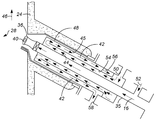
Fig. 2 is a schematic view of a portion of the schematic view of Fig. 1, showing in more detail one embodiment of a pyrolysis oil supply line. Fig.
이어지는 상세한 설명은 사실상 단지 예시적인 것이며, 본 발명 또는 본 출원 및 본 발명의 용도를 한정하려고 의도된 것은 아니다. 또한, 전술한 배경기술 또는 후술하는 상세한 설명에서 제시된 어떠한 이론에 의해서도 구속하고자 하는 바는 아니다.The following detailed description is merely exemplary in nature and is not intended to limit the invention or the application and uses of the invention. Further, it is not intended to be bound by any of the theories presented in the above-described background art or in the following detailed description.
본원에서는 열분해유 스트림 및 탄화수소 스트림을 개량하기 위한 방법 및 연료 처리 장치가 제공된다. 본원에서 지칭하는 바와 같이, "개량"은 비교적 높은 비등점 탄화수소의 낮은 비등점 탄화수소로의 전환을 가리킨다. 개량 공정은 일반적으로 탄화수소 스트림 및 열분해유 스트림을 수송 연료로서 사용하기에 적합하게 한다. 본원에 기술된 방법 및 연료 처리 장치에서, 열분해유 스트림과 탄화수소 스트림의 혼합물은 반응 구역에서 입자성 분해 촉매의 존재 하에 접촉 분해된다. 본원에서 지칭하는 바와 같은 반응 구역은, 입자성 분해 촉매가 열분해유 스트림 및/또는 탄화수소 스트림과 함께 혼합되는 영역 또는 공간이다. 접촉 분해는 100℃ 초과의 온도에서 실시되며, 탄화수소 스트림은 일반적으로 100℃ 초과의 온도로 제공된다. 그러나, 열분해유는 일반적으로 100℃ 초과의 온도에서 중합되어 장치 내에 침착물(deposit)을 형성한다. 침착물 형성은, 반응 구역으로 이어지는 공급 라인에 비하면 반응 구역에서는 그다지 우려되는 것이 아니다. 특히, 반응 구역에서의 침착물 형성은 일반적으로, 입자성 분해 촉매 상에 침착된 화합물의 형성을 초래한다. 입자성 분해 촉매는 그에 존재하는 침착된 화합물의 양이 많아도 종래의 공정을 통해 재생될 수 있기 때문에, 입자성 분해 촉매 상에 침착된 화합물의 형성에 의해 연료 처리 장치의 작동이 크게 영향을 받는 것은 아니다. 그러나, 반응 구역으로 이어지는 공급 라인에서의 침착물 형성은 막힘을 유발할 수 있으며, 이는 연료 처리 장치의 정지 및 막힌 공급 라인의 청소를 요한다. 따라서, 반응 구역으로 이어지는 공급 라인에서 열분해유 스트림 내의 중합에 기인하는 침착물 형성을 최소화하기 위해, 본원에 기술된 방법 및 연료 처리 장치는 열분해유 스트림에 침착물 형성이 막힘을 유발할 수 있는 구조물이 없을 때까지, 열분해유 스트림의 온도 상승을 최소화하도록 적합하게 된다.A method and a fuel treatment apparatus for improving a pyrolysis oil stream and a hydrocarbon stream are provided herein. As referred to herein, "improved" refers to the conversion of relatively high boiling hydrocarbons to low boiling hydrocarbons. The upgrading process generally makes the hydrocarbon stream and pyrolysis oil stream suitable for use as a transportation fuel. In the process and fuel treatment apparatus described herein, a mixture of a pyrolysed oil stream and a hydrocarbon stream is contact cracked in the presence of a particulate cracking catalyst in the reaction zone. The reaction zone as referred to herein is the region or space in which the particulate cracking catalyst is mixed with the pyrolyzed oil stream and / or the hydrocarbon stream. The catalytic cracking is carried out at a temperature in excess of < RTI ID = 0.0 > 100 C < / RTI > However, the pyrolysis oil is generally polymerized at temperatures above 100 ° C to form deposits in the apparatus. Deposition formation is less of a concern in the reaction zone as compared to the feed line leading to the reaction zone. In particular, formation of deposits in the reaction zone generally results in the formation of compounds deposited on the particulate decomposition catalyst. Since the particulate decomposition catalyst can be regenerated through conventional processes even if the amount of the deposited compound present therein is large, the operation of the fuel treatment apparatus is greatly affected by the formation of the compound deposited on the particulate decomposition catalyst no. Formation of deposits in the feed line leading to the reaction zone, however, can lead to clogging, which requires the stopping of the fuel treatment unit and the cleaning of the clogged feed line. Thus, in order to minimize formation of deposits due to polymerization in the pyrolysis oil stream in the feed line leading to the reaction zone, the methods and fuel treatment apparatus described herein are useful for reducing the formation of deposits in the pyrolysis oil stream Until it is no longer present, to minimize the temperature rise of the pyrolysis oil stream.
본원에 기술된 방법 및 연료 처리 장치에 따라 열분해유 스트림의 온도 상승을 최소화하기 위해, 열분해유 스트림 및 탄화수소 스트림은, 경우에 따라 운반 기체의 존재 하에 반응 구역으로 개별적으로 도입되며, 열분해유 스트림의 온도는 실질적으로 반응 구역으로의 도입까지 100℃ 이하의 온도로 유지된다. 열분해유 스트림의 온도는, 이하에 보다 상세히 기술하는 바와 같은 여러 가지 상이한 방식으로 유지될 수 있다. 어떠한 특정 이론에도 구속되지 않고, 열분해유 스트림의 100℃ 이상의 온도 상승은, 열분해유 스트림 내의 중합으로 인한 과도한 침착물 형성을 초래하는 것으로 생각된다. 열분해유 스트림의 온도를, 실질적으로 반응 구역으로의 도입까지는 100℃ 이하의 온도로 유지함으로써, 침착물 형성이 막힘을 유발할 수 있는, 반응 구역 외부의 연료 처리 장치 내의 구조물과 열분해유 스트림이 접촉하는 동안에는 적어도, 반응 구역으로 열분해유 스트림을 도입하기 전의 침착물 형성을 최소화한다.In order to minimize the temperature rise of the pyrolysis oil stream in accordance with the methods and fuel treatment apparatus described herein, the pyrolysis oil stream and the hydrocarbon stream are optionally introduced separately into the reaction zone in the presence of a carrier gas, The temperature is maintained at a temperature of 100 DEG C or below until introduction into the reaction zone. The temperature of the pyrolysis oil stream may be maintained in a number of different ways as described in more detail below. Without being bound by any particular theory, it is believed that a temperature rise of 100 ° C or more in the pyrolysis oil stream results in the formation of excessive deposits due to polymerization in the pyrolysis oil stream. By keeping the temperature of the pyrolysis oil stream substantially at or below 100 ° C until introduction into the reaction zone, the structure and pyrolysis oil stream in the fuel processor outside the reaction zone, which can cause blockage formation, During contact, at least the formation of deposits prior to introduction of the pyrolysis oil stream into the reaction zone is minimized.
이하, 개량된 열분해유를 제조하는 방법의 한 예시적 실시양태를, 도 1에 도시된 예시적 연료 처리 장치(10)를 참조하여 다룰 것이다. 이 실시양태에서, 연료 처리 장치(10)는 열분해 유닛(12) 및 유동 접촉 분해(FCC) 유닛(14)을 포함한다. 열분해 유닛(12)은, 예컨대 최근 개발된 급속 열분해를 통해, 바이오매스 스트림(18)을 열분해하여 열분해유 스트림(16)을 생성함으로써 열분해유 스트림(16)을 제공한다. 급속 열분해는 바이오매스 스트림(18), 예컨대 목재 폐기물, 농업 폐기물, 에너지용으로 의도적으로 재배하고 수확한 바이오매스 등을, 열분해 유닛(12)에서 공기의 부재 하에 450℃ ∼ 600℃로 급속히 가열하는 공정이다. 이들 조건 하에서, 유기 증기, 수증기 및 열분해 가스를 포함하는 열분해 증기 스트림이 챠(재 및 가연성 탄화수소 고체를 포함함)와 함께 생성된다. 열분해 증기 스트림의 일부분은 열분해 유닛(12) 내의 응축 시스템에서 응축되어 열분해유 스트림(16)을 생성한다. 열분해유 스트림(16)은 산소 함량을 갖는 복합적인 유기 액체이며, 물 또한 함유할 수 있다. 예를 들어, 열분해유 스트림(16)의 산소 함량은, 열분해유 스트림(16)의 총 중량을 기준으로 30 ∼ 60 중량%, 예컨대 40 ∼ 55 중량%일 수 있다. 물은 열분해유 스트림(16)의 총 중량을 기준으로 10 ∼ 35 중량%, 예컨대 20 ∼ 32 중량%의 양으로 열분해유 스트림(16)에 존재할 수 있다. 다른 실시양태에서는, 도시하지는 않았으나, 열분해유 스트림(16)을 함유하는 용기와 같은 임의의 열분해유 공급원으로부터 열분해유 스트림(16)이 제공될 수 있으며, 본원에 기술된 방법은 임의의 특정한 공급원으로부터 열분해유 스트림(16)을 제공하는 것으로 한정되지 않는다는 것이 이해되어야 한다. 한 실시양태에서는, 열분해 유닛(12)으로부터 배출된 후 침착물 형성을 초래할 수 있는 열분해유 스트림(16)의 중합을 최소화하기 위해서, 열분해유 스트림(16)이 열분해 유닛(12)으로부터 100℃ 이하, 예컨대 80℃ 이하의 온도로 제공된다.Hereinafter, one exemplary embodiment of a method for producing an improved pyrolysis oil will be described with reference to the exemplary
본원에서 고안된 예시적 방법에 따르면, 탄화수소 스트림(20)이 또한 제공된다. 본원에서 지칭하는 바와 같이, "탄화수소 스트림"은 탄화수소의 석유계 공급원을 가리킨다. 탄화수소 스트림(20)은 열분해유 스트림(16)과 별도로 제공되며, 열분해유 스트림(16) 및 탄화수소 스트림(20)이 이하에 보다 상세히 설명하는 바와 같이 반응 구역(28)에 개별적으로 도입된다. 탄화수소 스트림(20)은 신선한 탄화수소 스트림을 포함하거나, 다른 정제 처리로부터의 정제된 탄화수소 스트림을 포함할 수 있다. 한 실시양태에서, 탄화수소 스트림(20)은 감압 가스유이며, 이것은 FCC 유닛에서 개량되는 일반적인 탄화수소 스트림(20)이다. 탄화수소 스트림(20)은 임의의 공급원으로부터 제공될 수 있으며, 본원에 기술된 방법은 임의의 특정한 공급원으로부터 탄화수소 스트림(20)을 제공하는 것으로 한정되지 않는다는 것이 이해되어야 한다. 실시양태에서, 탄화수소 스트림(20)은 열분해유 스트림(16)보다 높은 온도로 제공되며, 또한 열분해유 스트림(16)보다 높은 온도로 반응 구역(28)에 도입되는데, 고온으로 인한 탄화수소 스트림(20)으로부터의 침착물 형성의 위험이 적기 때문이고, 고온의 탄화수소 스트림(20)이 접촉 분해를 촉진하기 때문이다. 한 실시양태에서, 탄화수소 스트림(20)은 100℃ 이상, 예컨대 100℃ ∼ 425℃, 예를 들어 200℃ ∼ 300℃의 온도로 제공된다.According to an exemplary method devised herein, a
도 1을 참조하면, 본원에서 고안된 FCC 유닛(14)의 예시적 실시양태는 반응 구역(28), 열분해유 공급 라인(35) 및 탄화수소 공급 라인(34)을 포함한다. 특히, 입자성 분해 촉매(30)는 반응 구역(28)에서 탄화수소 스트림(20)과 열분해유 스트림(16)의 혼합물(46)과 접촉된다. 열분해유 공급 라인(35)은 반응 구역(28)에 열분해유 스트림(16)을 도입하기 위한, 반응 구역(28)으로의 열분해유 배출구(36)를 갖는다. 한 실시양태에서 및 도 2에 도시된 바와 같이, 열분해유 공급 라인(35)은 열분해유 스트림(16)을 반응 구역(28)에 분무 또는 분사하기 위한 공급물 분산 선단부(40)를 더 포함하며, 열분해유 배출구(36)가 공급물 분산 선단부(40)에 위치한다. 탄화수소 공급 라인(34)은 열분해유 스트림(16)과 별도로, 반응 구역(28)에 탄화수소 스트림(20)을 도입하기 위한, 반응 구역(28)으로의 탄화수소 배출구(38)를 갖는다. 상기 예시적 방법은 열분해유 스트림(16) 및 탄화수소 스트림(20)을 반응 구역(28)에 개별적으로 도입하여 반응 구역(28)에서 열분해유 스트림(16)과 탄화수소 스트림(20)의 혼합물(46)을 형성하는 것으로 이어진다.Referring to FIG. 1, an exemplary embodiment of an
열분해유 스트림(16) 및 탄화수소 스트림(20)을 반응 구역(28)에 개별적으로 도입함으로써, 열분해유 스트림(16)의 온도 상승이 제어될 수 있고 열분해유 스트림(16)의 온도가, 실질적으로 반응 구역(28)로의 도입까지, 예컨대 실질적으로 반응 구역(28)으로의 열분해유 배출구(36)까지, 100℃ 이하, 예컨대 80℃ 이하로 유지될 수 있다. 이와 관련하여, 열분해유 공급 라인(35)은 열분해유 공급 라인(35)을 통해 유동하는 열분해유 스트림(16)의 외부 가열을 억제하도록 적합하게 된다. 본원에서 지칭하는 바와 같이, "실질적으로 ∼까지"는 반응 구역(28)으로의 열분해유 배출구(36)와 인접하나 열분해유 공급 라인(35) 내에서 열분해유 배출구(36)의 상류인, 열분해유 공급 라인(35) 내의 위치, 예컨대 열분해유 공급 라인(35) 내에서 열분해유 배출구(36)와 가장 근접한 위치를 가리키며, 여기서 열분해유 공급 라인(35)의 단열 또는 능동적 외부 냉각이 실시된다. 열분해유 스트림(16)이 열분해유 배출구(36)를 통과하기 전에도, 열분해유 스트림(16)의 온도가 실질적으로 반응 구역(28)으로의 도입까지 100℃ 이하로 유지되는 한, 전술한 수치 이상의 경미한 온도 상승은 허용됨을 이해해야 한다. 한 실시양태에서, 열분해유 스트림(16)을 능동 냉각시킴으로써, 열분해유 스트림(16)의 온도를 100℃ 이하로 유지시킨다. 본원에서 지칭하는 바와 같은 능동적 냉각은, 단열 처리만을 이용하여 열분해유 스트림(16)을 단열시키는 것과는 대조적으로, 냉각의 정도를 증가 또는 감소시킬 수 있는 조절 가능한 냉각 활동에 의해 열분해유 스트림(16)을 냉각시키는 것을 의미한다. 다른 실시양태에서는, 열분해유 스트림(16)을, 예컨대 열분해 유닛(12)으로부터, 능동적 냉각이 필요하지 않을 정도로 충분히 낮은 온도로 제공하며, 열분해유 스트림(16)의 온도를 100℃로 유지하고 반응 구역(28)에서 열분해유 공급 라인(35)으로의 열 전도로 인한 100℃ 이상의 온도 상승을 방지하기 위해서 열분해유 공급 라인(35)을 충분히 단열시킨다.By separately introducing the
실시양태에서, 능동적 냉각은 외부 냉매(42)에 의한 열분해유 스트림(16)의 외부적 냉각 및/또는 열분해유 스트림(16)에 첨가된 보충 성분(52)에 의한 열분해유 스트림(16)의 내부적 냉각에 의해 실시될 수 있다. 한 실시양태에서 및 도 2에 도시된 바와 같이, 열분해유 공급 라인(35) 내의 열분해유 스트림(16)은, 열분해유 공급 라인(35)을 외부 냉각시키는 외부 냉매(42)로 외부 냉각시킴으로써, 열분해유 공급 라인(35)의 벽(44)을 통한 열분해유 스트림(16)의 외부 가열을 억제한다. 이 실시양태에서, 외부 냉매(42)는 냉각 유체(42)이며, 액체 또는 기체일 수 있다. 예를 들면, 공기, 증기 및 FCC 생성물 가스가 효과적인 냉각 유체(42)의 예이다. 냉각 유체(42)는, 외부 열에 대한 노출로부터 열분해유 공급 라인(35)을 완충해주는, 열분해유 공급 라인(35)의 벽(44)와 접촉한다. 한 실시양태에서, 도 1 및 도 2에 도시된 바와 같이, 냉각 유체(42)의 유동을 지지하는 냉각 재킷(48)이 열분해유 공급 라인(35) 주변에 배치되어, 냉각 유체(42)를 열분해유 공급 라인(35)의 벽(44)과 접촉시킨다. 또한, 도 2에 도시된 바와 같이, 냉각 유체(42)는 반응 구역(28)에 직접 노출될 수 있는 냉각 재킷(48)의 외벽(45)과 접촉함으로써, 반응 구역(28)으로부터 공급물 분산 선단부(40) 주위에 유입되는 기체로부터 열을 가져가며[그렇지 않으면, 열은 열분해유 공급 라인(35)을 통해 유동하는 열분해유 스트림(16)의 온도 상승을 초래할 수 있음], 이에 의해, 그렇지 않으면 발생할 수 있는 열분해유 스트림(16)의 온도 상승을 최소화한다. 냉각 재킷(48)은 냉각 유체 주입구(50), 열분해유 공급 라인(35)의 벽(44) 부근에 배치된 내부 유로(54), 열분해유 공급 라인(35)으로부터 내부 유로(54)의 맞은 편 상에서 열분해유 공급 라인(35)의 벽(44)으로부터 이격되어 있는 외부 유로(56), 및 냉각 유체 배출구(58)를 포함한다. 냉각 유체 주입구(50)는 도 1에 도시된 바와 같이, 냉각 유체 공급원(43), 예컨대 공기 압축기로부터 냉각 재킷(48)으로의 냉각 유체(42)의 유동을 지지한다. 일단, 냉각 재킷(48)에서, 냉각 유체(42)가 열분해유 공급 라인(35)의 벽(44)과 접촉하고 있는 내부 유로(54)를 통해 유동한다. 실시양태에서 및 도 2에 도시된 바와 같이, 내부 유로(54)는 실질적으로 반응 구역(28)으로의 열분해유 배출구(36)까지 연장되고, 여기서 이어서 냉각 유체(42)가 외부 유로(56)로 유입되며, 그 다음에 냉각 유체(42)는 냉각 유체 배출구(58)를 통해 냉각 재킷(48) 외부로 반송된다. 이 실시양태에서, 도시하지는 않았으나, 냉각 유체(42)가 폐회로에서 처리될 수 있으며, 여기서 냉각 유체 배출구(58)를 통해 배출되는 냉각 유체(42)는 냉각되어 냉각 재킷(48)의 냉각 유체 주입구(50)로 복귀된다. 대안적인 실시양태에서, 도시하지는 않았으나, 냉각 재킷(48)의 냉각 유체 배출구(58)는 열분해유 배출구(36)에 인접하여 배치될 수 있고, 냉각 유체(42)는 열분해유 스트림(16)과 함께 반응 구역(28)으로 배출될 수 있다. 이 실시양태에서는, 냉각 재킷(48)에 외부 유로(56)가 없다. 또한 이 실시양태에서, 반응 구역(28)에서의 접촉 분해 반응에 대한, 공기 중에 존재하는 산소의 잠재적인 영향을 회피하기 위해, 냉각 유체(42)가 증기 또는 FCC 생성물 가스일 수 있다. 특정한 공정 파라미터들, 예컨대 냉각 유체(42)의 유속, 냉각 유체(42)의 주입구 온도, 열분해유 공급 라인(35)의 벽(44)과 냉각 유체(42) 사이의 접촉 면적, 냉각 유체(42)와 냉각 재킷(48)의 외벽(45) 사이의 접촉 면적, 냉각 유체 조성, 및 열분해유 스트림(16)을 실질적으로 반응 구역(28)으로의 도입까지 100℃ 이하의 온도로 유지하는 것과 관련된 기타 고려 사항은, 당업자에 의해 용이하게 결정될 수 있는 설계 고려 사항이다.In an embodiment, the active cooling may be accomplished by external cooling of the pyrolysed
다른 실시양태에서, 상기 언급한 바와 같이, 열분해유 스트림(16)은 열분해유 스트림(16)에 첨가되는 보충 성분(52)을 이용하여 내부적으로 냉각한다. 열분해유 스트림(16)을 내부적으로 냉각시키면서 열분해유 스트림(16)을 외부 냉각시켜, 열분해유 스트림(16)을 실질적으로 반응 구역(28)으로의 도입까지 100℃ 이하의 온도로 유지할 수 있다. 한 실시양태에서, 열분해유 스트림(16)은 열분해유 공급 라인(35)을 통해 유동하는 열분해유 스트림(16)에 보충 성분(52)을 첨가함으로써 내부적으로 냉각시킨다. 보충 성분(52)은, 예를 들어 반응 구역(28)으로의 열분해유 스트림(16)의 도입에 조력하기 위해 열분해유 스트림(16)에 첨가되는 운반 기체(52)일 수 있다. 이 실시양태에서, 운반 기체(52) 및 열분해유 스트림(16)은 열분해유 스트림(16)을 반응 구역(28)에 도입하기 전에 혼합되어, 역시 열분해유 스트림(16)을 내부적으로 냉각시킨다. 운반 기체(52)는 FCC 생성물 가스, 증기, 및/또는 불활성 기체, 예컨대 질소일 수 있다. 보충 성분(52)으로 열분해유 스트림(16)을 냉각시키기 위해서, 보충 성분(52)은 100℃ 이하, 예컨대 80℃ 이하, 또는 예컨대 10℃ 미만의 온도로 제공된다. 운반 기체(52)를 이용하여 열분해유 스트림(16)을 내부적으로 냉각시키는 조건 하에서는, 운반 기체(52)를 열분해유 스트림(16)에 비해 비교적 적은 양으로 사용하기 때문에, 운반 기체(52)는 냉각을 유발하기 위해 사용하는 운반 기체의 특정 유형에 따라서는, 실질적으로 10℃ 미만의 온도로 제공될 수 있다.In another embodiment, as noted above,
본원에서 고안된 방법의 예시적 실시양태에 따르면, 바이오매스 스트림(18)의 열분해로부터 생성된 열분해유 스트림(16)은, 열분해유 스트림(16)의 개량 공정의 개입 없이 반응 구역(28)에 도입한다. 개량 공정의 개입은 탈산소화, 분해, 수소 처리 등을 포함하나, 이에 한정되는 것은 아니다. 한 실시양태에서, 열분해유 스트림(16)은 열분해 유닛(12)으로부터의 응축된 생성물 스트림으로서 직접적으로 제공된다.The
본원에 기술한 방법은, 열분해유 스트림(16) 대 탄화수소 스트림(20)의 비율과는 상관없이, 열분해유 스트림(16)을 반응 구역(28)에 도입하기 전에 열분해유 스트림(16)으로부터의 침착물 형성을 최소화하는 데에 효과적이긴 하나, 입자성 분해 촉매(30) 상의 과도한 침착물 형성은 열분해유 스트림(16)과 탄화수소 스트림(20)이 혼합되는 비율을 조정함으로써 방지할 수도 있다. 한 실시양태에서, 열분해유 스트림(16)과 탄화수소 스트림(20)은, 열분해유 스트림(16) 대 탄화수소 스트림(20)의 중량비가 0.005:1 ∼ 0.2:1, 예컨대 0.01:1 ∼ 0.05:1로 혼합된다. 전술한 중량비 내에서, 열분해유 스트림(16)은 열분해유 스트림(16)과 탄화수소 스트림(20)의 혼합물(46) 내에서 충분히 희석되어, 입자성 분해 촉매(30) 상의 과도한 침착물 형성이 방지되며, 이에 의해 유동 접촉 분해 유닛(14) 내에서의 입자성 분해 촉매(30)의 선택성 및 촉매 활성에 대한 영향, 또는 촉매 재생기(70) 내의 과도한 열 발생이 방지된다.The process described herein is advantageous in that the
예시적 방법은, 입자성 분해 촉매(30)의 존재 하에 열분해유 스트림(16)과 탄화수소 스트림(20)의 혼합물(46)을 접촉 분해하는 단계로 이어진다. 이와 관련하여, 입자성 분해 촉매(30)는 먼저 탄화수소 스트림(20) 또는 열분해유 스트림(16)중 하나와 혼합된 후, 탄화수소 스트림(20) 또는 열분해유 스트림(16) 중 다른 하나와 혼합될 수 있다. 입자성 분해 촉매(30)는 일반적으로, 열분해유 스트림(16) 및 탄화수소 스트림(20)의 혼합물(46)의 접촉 분해를 촉진하기에 충분한 온도로 반응 구역(28)에 도입되기 때문에, 접촉 분해는 일반적으로 입자성 분해 촉매(30)가 탄화수소 스트림(20) 및/또는 열분해유 스트림(16)과 혼합될 때에 개시된다.The exemplary method leads to the step of catalytically cracking the
예시적 실시양태에서 및 도 1에 도시된 바와 같이, FCC 유닛(14)의 반응 구역(28)은 수직 도관 또는 라이저(riser)(24)에 포함되어 있다. 한 실시양태에서, 열분해유 스트림(16) 및 탄화수소 스트림(20)의 혼합물(46)을 접촉 분해하는 단계는, 반응 구역(28)에서 입자성 분해 촉매(30)와 열분해유 스트림(16) 및/또는 탄화수소 스트림(20)을 혼합하는 단계를 포함한다. 예를 들어, 한 실시양태에서 및 도 1에 도시된 바와 같이, 탄화수소 스트림(20)은 탄화수소 배출구(38)로부터 라이저(24)로 도입되며, 탄화수소 배출구(38)는 열분해유 배출구(36)의 상류에 위치한다. 이 실시양태에서 입자성 분해 촉매(30)는, 탄화수소 배출구(38)의 하류이나 열분해유 배출구(36)의 상류에 있는 촉매 배출구(31)에서 반응 구역(28)으로 도입됨으로써, 반응 구역(28)에 열분해유 스트림(16)이 도입되기 전에 입자성 분해 촉매(30)가 먼저 탄화수소 스트림(20)과 혼합될 수 있다. 이러한 탄화수소 배출구(38), 촉매 배출구(31) 및 열분해유 배출구(36)의 배열은, 반응 구역(28)에 상대적으로 저온의 열분해유 스트림(16)을 도입하기 전에, 반응 구역(28) 내의 반응 온도를 용이하게 최적화하는 것을 가능하게 할 수 있다. 그러나, 본원에 기술된 방법은 탄화수소 배출구(38), 촉매 배출구(31) 및 열분해유 배출구(36)의 상기 상대적 위치로 특히 한정되는 것은 아니며, 탄화수소 배출구(38), 촉매 배출구(31) 및 열분해유 배출구(36)의 임의의 상대적 위치가, 상류에서든, 하류에서든, 또는 서로 동류(evenstream)에서, 본원에 기술된 방법에 따라 실현 가능함을 이해해야 한다. 한 실시양태에서 및 도 2에 도시된 바와 같이, 열분해유 스트림(16)은 라이저(24) 내의 유동 방향을 향하는 각도로 반응 구역(28)에 도입되어, 열분해유 배출구(36)를 마주하는 라이저(24)의 벽과의 열분해유 스트림(16)의 접촉을 최소화하며, 이에 의해 열분해유 스트림(16)에 기인하는 라이저(24) 벽 상의 침착물 형성을 최소화한다. 라이저(24)에서의 입자성 분해 촉매(30) 및 열분해유 스트림(16)과 탄화수소 스트림(20)의 혼합물(46)의 체류 시간은 일반적으로 단지 몇 초이다. FCC 유닛 중 반응 구역(28)에 대한 일반적인 작동 조건은 업계에 공지되어 있다.In an exemplary embodiment and as shown in FIG. 1, the
열분해유 스트림(16)과 탄화수소 스트림(20)의 혼합물(46)의 접촉 분해는, 소비된 입자성 분해 촉매(76) 및 기체 성분(60)을 포함하는 유출물(59)을 생성한다. 기체 성분(60)은 반응 구역(28)에서의 반응으로부터의 생성물, 예컨대 분해된 탄화수소를 포함하며, 분해된 탄화수소는 다양한 비등점을 갖는 개량된 연료 제품을 얻기 위해 응축될 수 있다. 개량된 연료 제품의 예는 프로판, 부탄, 나프타, 경질 사이클 오일(light cycle oil) 및 중질 연료유(heavy fuel oil)를 포함하나, 이에 한정되는 것은 아니다. 고안된 방법의 실시양태에 따르면, 소비된 입자성 분해 촉매(76) 및 기체 성분(60)이 분리된다. 이 실시양태에서, 및 도 1에 도시된 바와 같이, FCC 유닛(14)은 반응 구역(28)과 유체 연통된 분리기 용기(62)을 더 포함한다. 분리기 용기(62)는 소비된 입자성 분해 촉매(76)를 유출물(59)로부터 분리한다. 분리기 용기(62)는 통상, 분리기 용기(62) 내의 정상부에 위치하는 고체-증기 분리 장치(64)를 포함할 수 있다. 분리기 용기(62)에서, 유출물(59)의 기체 성분(60)은 소비된 입자성 분해 촉매(76)로부터 분리되며, 기체 성분(60)은 생성물 라인(66)을 통해서 분리기 용기(62)로부터 배출될 수 있다. 도시하지는 않았으나, 기체 성분(60)은 개량된 연료 제품을 얻기 위해 압축될 수 있으며, 응축되지 않은 FCC 생성물 가스는 실시양태에서 냉각 유체(42) 및/또는 운반 기체(52)로 사용하기 위해 재활용될 수 있다. 한 실시양태에서, 소비된 입자성 분해 촉매(76)는 분리기 용기(62)의 저부에 위치한 스트리퍼(68)로 강하한다. 스트리퍼(68)는 추가의 촉매 재생에 앞서, 침착된 화합물을 소비된 입자성 분해 촉매(76)로부터 제거하는 데 조력한다.Catalytic cracking of the
한 실시양태에서, FCC 유닛(14)은, 분리기 용기(62) 및 또한 반응 구역(28)과 유체 연통된 촉매 재생기(70)를 더 포함한다. 기체 성분(60)으로부터 분리된, 소비된 입자성 분해 촉매(76)는 스트리퍼(68)로부터 촉매 재생기(70)로 도입되며, 소비된 입자성 분해 촉매(476)를 산소 함유 재생 가스와 접촉시킴으로써, 촉매 재생기(70)에서 소비된 입자성 분해 촉매(76)로부터 침착된 화합물을 제거한다. 한 실시양태에서, 소비된 입자성 분해 촉매(76)는 촉매 재생기(70)와 스트리퍼(68) 사이에 연결된 제1 이송 라인(72)을 통해 촉매 재생기(70)에 이송된다. 또한, 반응 구역(28)과 유체 연통된 촉매 재생기(70)는 재생된 입자성 촉매(30)를 반응 구역(28)으로 이송한다. 도 1에 도시된 바와 같은 FCC 유닛(14)에서, 입자성 분해 촉매(30)는, 예컨대 제2 이송 라인(74)을 통해, 반응 구역(28)으로부터 촉매 재생기(70)로, 그 다음 다시 반응 구역(28)으로 연속적으로 순환된다.In one embodiment, the
앞선 본 발명의 상세한 설명에서 하나 이상의 예시적 실시양태를 제시한 동안, 다수의 변형예가 존재함이 이해되어야 한다. 예시적 실시양태 또는 예시적 실시양태는 단지 예시이며, 본 발명의 범위, 적용성 또는 구성을 어떤 식으로든 한정하려는 것은 아님이 역시 이해되어야 한다. 오히려, 전술한 상세한 설명은 당업자에게 본 발명의 예시적 실시양태를 실시하기 위한 편리한 로드맵을 제공할 것이다. 첨부의 특허청구범위에 개시된 바와 같은 본 발명의 범위를 벗어나지 않으면서, 예시적 실시양태에 기술된 요소들의 배열 및 기능에 다양한 변화가 이루어질 수 있음이 이해된다.In the foregoing Detailed Description of the Invention, it should be understood that there are many variations while presenting one or more exemplary embodiments. It is also to be understood that the exemplary embodiments or example embodiments are illustrative only and are not intended to limit the scope, applicability or configuration of the invention in any way. Rather, the foregoing detailed description will provide those skilled in the art with a convenient road map for implementing the exemplary embodiments of the present invention. It is understood that various changes may be made in the arrangement and function of the elements described in the exemplary embodiments without departing from the scope of the invention as set forth in the appended claims.
Claims (10)
열분해유 스트림 및 탄화수소 스트림을 반응 구역으로 개별적으로 도입하여, 반응 구역에서 열분해유 스트림과 탄화수소 스트림의 혼합물을 형성하는 단계;
반응 구역에서 입자성(particulate) 분해 촉매의 존재 하에 열분해유 스트림과 탄화수소 스트림의 혼합물을 접촉 분해하는 단계; 및
열분해유 스트림을, 실질적으로 반응 구역으로의 도입까지 100℃ 이하의 온도로 유지하는 단계
를 포함하는 방법.As a method for improving pyrolysis oil stream and hydrocarbon stream,
Separately introducing the pyrolysis oil stream and the hydrocarbon stream into the reaction zone to form a mixture of the pyrolysis oil stream and the hydrocarbon stream in the reaction zone;
Catalytically cracking a mixture of a pyrolyzed oil stream and a hydrocarbon stream in the presence of a particulate cracking catalyst in the reaction zone; And
Maintaining the pyrolysis oil stream at a temperature of 100 DEG C or lower until substantially introduction into the reaction zone
≪ / RTI >
열분해유 공급 라인을 통해서 열분해유 스트림을, 그리고 탄화수소 공급 라인을 통해서 탄화수소 스트림을 반응 구역으로 개별적으로 도입하여, 반응 구역에서 열분해유 스트림과 탄화수소 스트림의 혼합물을 형성하는 단계로서, 상기 열분해유 공급 라인은 반응 구역으로의 열분해유 배출구를 포함하고, 상기 탄화수소 공급 라인은 반응 구역으로의 탄화수소 배출구를 포함하는 것인 단계;
반응 구역에서 입자성 분해 촉매의 존재 하에 열분해유 스트림과 탄화수소 스트림의 혼합물을 접촉 분해하는 단계;
열분해유 스트림을, 실질적으로 반응 구역으로의 열분해유 배출구까지, 열분해유 공급 라인에서 100℃ 이하의 온도로 유지하는 단계
를 포함하는 방법.A method for improving a pyrolysis oil stream and a hydrocarbon stream in a flow catalytic cracking unit comprising a reaction zone,
Separately introducing a pyrolysis oil stream through a pyrolysis oil feed line and a hydrocarbon stream into a reaction zone through a hydrocarbon feed line to form a mixture of a pyrolyzed oil stream and a hydrocarbon stream in a reaction zone, Comprising a pyrolysis oil outlet to the reaction zone, wherein the hydrocarbon feed line comprises a hydrocarbon outlet to the reaction zone;
Catalytically cracking a mixture of a pyrolysis oil stream and a hydrocarbon stream in the presence of a particulate decomposition catalyst in a reaction zone;
Maintaining the pyrolysis oil stream at a temperature of 100 DEG C or below in the pyrolysis oil feed line to substantially the pyrolysis oil outlet to the reaction zone
≪ / RTI >
바이오매스 스트림을 열분해하여 열분해유 스트림을 생성하기 위한 열분해 반응기; 및
유동 접촉 분해 유닛
을 포함하며, 상기 유동 접촉 분해 유닛은
입자성 분해 촉매가 탄화수소 스트림과 열분해유 스트림의 혼합물과 접촉하는 반응 구역;
반응 구역으로 열분해유 스트림을 도입하기 위한, 반응 구역으로의 열분해유 배출구를 갖는 열분해유 공급 라인으로서, 그를 통해 유동하는 열분해유 스트림의 외부 가열을 억제하도록 적합하게 된 것인 열분해유 공급 라인; 및
열분해유 스트림과 별도로 반응 구역으로 탄화수소 스트림을 도입하기 위한, 반응 구역으로의 탄화수소 배출구를 갖는 탄화수소 공급 라인
을 포함하는 것인 장치.A fuel processing apparatus comprising:
A pyrolysis reactor for pyrolyzing the biomass stream to produce a pyrolysed oil stream; And
Flow contact decomposition unit
, Wherein the flow contact decomposition unit
A reaction zone in which the particulate decomposition catalyst is in contact with a mixture of a hydrocarbon stream and a pyrolysis oil stream;
A pyrolysis oil feed line having a pyrolysis oil outlet to the reaction zone for introducing a pyrolysis oil stream into the reaction zone, the pyrolysis oil feed line being adapted to inhibit external heating of the pyrolysis oil stream flowing therethrough; And
A hydrocarbon feed line having a hydrocarbon outlet to the reaction zone for introducing the hydrocarbon stream into the reaction zone separately from the pyrolysis oil stream
. ≪ / RTI >
Applications Claiming Priority (3)
| Application Number | Priority Date | Filing Date | Title |
|---|---|---|---|
| US13/563,172 US9663729B2 (en) | 2012-07-31 | 2012-07-31 | Methods and fuel processing apparatuses for upgrading a pyrolysis oil stream and a hydrocarbon stream |
| US13/563,172 | 2012-07-31 | ||
| PCT/US2013/040879 WO2014021975A1 (en) | 2012-07-31 | 2013-05-14 | Methods and fuel processing apparatuses for upgrading a pyrolysis oil stream and a hydrocarbon stream |
Publications (1)
| Publication Number | Publication Date |
|---|---|
| KR20150036184A true KR20150036184A (en) | 2015-04-07 |
Family
ID=50024433
Family Applications (1)
| Application Number | Title | Priority Date | Filing Date |
|---|---|---|---|
| KR1020157001939A KR20150036184A (en) | 2012-07-31 | 2013-05-14 | Methods and fuel processing apparatuses for upgrading a pyrolysis oil stream and a hydrocarbon stream |
Country Status (12)
| Country | Link |
|---|---|
| US (1) | US9663729B2 (en) |
| EP (1) | EP2880127B1 (en) |
| KR (1) | KR20150036184A (en) |
| CN (1) | CN104508086B (en) |
| AU (1) | AU2013297028A1 (en) |
| BR (1) | BR112015001657A2 (en) |
| CA (1) | CA2878917C (en) |
| ES (1) | ES2650457T3 (en) |
| IN (1) | IN2015DN00303A (en) |
| RU (1) | RU2599246C2 (en) |
| SG (1) | SG11201500269QA (en) |
| WO (1) | WO2014021975A1 (en) |
Cited By (1)
| Publication number | Priority date | Publication date | Assignee | Title |
|---|---|---|---|---|
| KR20190140675A (en) * | 2018-06-12 | 2019-12-20 | 한국에너지기술연구원 | Method for improving properties of pyrolysis oil produced from biomass |
Families Citing this family (12)
| Publication number | Priority date | Publication date | Assignee | Title |
|---|---|---|---|---|
| WO2016053780A1 (en) * | 2014-09-29 | 2016-04-07 | Uop Llc | Methods for reducing flue gas emissions from fluid catalytic cracking unit regenerators |
| US20160090539A1 (en) * | 2014-09-30 | 2016-03-31 | Uop Llc | Fcc units, apparatuses and methods for processing pyrolysis oil and hydrocarbon streams |
| US20160312127A1 (en) * | 2015-04-22 | 2016-10-27 | Uop Llc | Processes for minimizing catalyst fines in a regenerator flue gas stream |
| US10696906B2 (en) | 2017-09-29 | 2020-06-30 | Marathon Petroleum Company Lp | Tower bottoms coke catching device |
| US11975316B2 (en) | 2019-05-09 | 2024-05-07 | Marathon Petroleum Company Lp | Methods and reforming systems for re-dispersing platinum on reforming catalyst |
| CA3109675A1 (en) | 2020-02-19 | 2021-08-19 | Marathon Petroleum Company Lp | Low sulfur fuel oil blends for stability enhancement and associated methods |
| CA3203839A1 (en) * | 2020-12-29 | 2022-07-07 | Lummus Technology Llc | Catalytic cracking process for a true circular solution for converting pyrolysis oil produced from recycled waste plastic into virgin olefins and petrochemical intermediates |
| US20220268694A1 (en) | 2021-02-25 | 2022-08-25 | Marathon Petroleum Company Lp | Methods and assemblies for determining and using standardized spectral responses for calibration of spectroscopic analyzers |
| US11905468B2 (en) | 2021-02-25 | 2024-02-20 | Marathon Petroleum Company Lp | Assemblies and methods for enhancing control of fluid catalytic cracking (FCC) processes using spectroscopic analyzers |
| US11898109B2 (en) | 2021-02-25 | 2024-02-13 | Marathon Petroleum Company Lp | Assemblies and methods for enhancing control of hydrotreating and fluid catalytic cracking (FCC) processes using spectroscopic analyzers |
| US11692141B2 (en) | 2021-10-10 | 2023-07-04 | Marathon Petroleum Company Lp | Methods and systems for enhancing processing of hydrocarbons in a fluid catalytic cracking unit using a renewable additive |
| CA3188122A1 (en) | 2022-01-31 | 2023-07-31 | Marathon Petroleum Company Lp | Systems and methods for reducing rendered fats pour point |
Family Cites Families (20)
| Publication number | Priority date | Publication date | Assignee | Title |
|---|---|---|---|---|
| US5346133A (en) * | 1993-03-25 | 1994-09-13 | The M. W. Kellogg Company | High temperature liquid injection apparatus |
| US6042717A (en) | 1997-12-05 | 2000-03-28 | Uop Llc | Horizontal FCC feed injection process |
| BR9905840B1 (en) | 1999-12-14 | 2010-07-13 | load dispersing system of fluid catalytic cracking units. | |
| BR0205585A (en) * | 2002-10-29 | 2004-08-03 | Petroleo Brasileiro Sa | Fluid catalytic cracking process for high basic nitrogen hydrocarbon fillers |
| DE102004003667A1 (en) * | 2004-01-24 | 2005-08-11 | Nill Tech Gmbh | Recovering fractionated hydrocarbons from plastics and/or oil residues comprises compression, melting, evaporation, heating, cracking and condensing |
| CA2502635A1 (en) | 2005-03-29 | 2006-09-29 | Nova Chemicals Corporation | Reduction of fouling in thermal processing of olefinic feedstocks |
| EP1892280A1 (en) | 2006-08-16 | 2008-02-27 | BIOeCON International Holding N.V. | Fluid catalytic cracking of oxygenated compounds |
| GB2447684B (en) * | 2007-03-21 | 2011-11-23 | Statoil Asa | Biogasoline |
| CN101314724B (en) * | 2007-05-31 | 2013-03-06 | 中国石油化工股份有限公司 | Combined catalytic conversion method for biological oil and fat and mineral oil |
| EP2184335B1 (en) | 2007-08-09 | 2021-03-31 | China Petroleum & Chemical Corporation | A process of catalytic conversion |
| US7794585B2 (en) | 2007-10-15 | 2010-09-14 | Uop Llc | Hydrocarbon conversion process |
| CN101214919B (en) * | 2007-12-26 | 2011-03-23 | 中国科学院广州能源研究所 | Method for preparing synthetic gas by gasifying biological oil and device thereof |
| EP2486107A1 (en) | 2009-10-09 | 2012-08-15 | Velocys Inc. | Process for treating heavy oil |
| BR112012010055A8 (en) * | 2009-10-27 | 2017-10-17 | Ignite Energy Resources Ltd | methods for producing hydrocarbon products from bio-oils and / or coal oils |
| US8471081B2 (en) | 2009-12-28 | 2013-06-25 | Uop Llc | Production of diesel fuel from crude tall oil |
| CN101870881B (en) * | 2010-06-21 | 2013-04-24 | 中国科学院广州能源研究所 | Method for preparing liquid alkane fuel by upgrading bio-oil in aqueous phase catalytic mode |
| BR112013005821A2 (en) * | 2010-09-14 | 2019-09-24 | Radlein Desmond | methods of transforming bio-oil into transport type hydrocarbon fuels |
| WO2012062924A1 (en) | 2010-11-12 | 2012-05-18 | Shell Internationale Research Maatschappij B.V. | Process for the preparation of a biofuel and/or biochemical |
| US8829258B2 (en) * | 2010-12-27 | 2014-09-09 | Phillips 66 Company | Integrated FCC biomass pyrolysis/upgrading |
| CA2819903C (en) | 2010-12-30 | 2019-06-18 | Kior Inc. | Production of renewable biofuels |
-
2012
- 2012-07-31 US US13/563,172 patent/US9663729B2/en active Active
-
2013
- 2013-05-14 KR KR1020157001939A patent/KR20150036184A/en not_active Application Discontinuation
- 2013-05-14 IN IN303DEN2015 patent/IN2015DN00303A/en unknown
- 2013-05-14 RU RU2015106999/04A patent/RU2599246C2/en active
- 2013-05-14 ES ES13825505.4T patent/ES2650457T3/en active Active
- 2013-05-14 CN CN201380040124.6A patent/CN104508086B/en active Active
- 2013-05-14 SG SG11201500269QA patent/SG11201500269QA/en unknown
- 2013-05-14 CA CA2878917A patent/CA2878917C/en active Active
- 2013-05-14 AU AU2013297028A patent/AU2013297028A1/en not_active Abandoned
- 2013-05-14 EP EP13825505.4A patent/EP2880127B1/en active Active
- 2013-05-14 BR BR112015001657A patent/BR112015001657A2/en not_active IP Right Cessation
- 2013-05-14 WO PCT/US2013/040879 patent/WO2014021975A1/en active Application Filing
Cited By (1)
| Publication number | Priority date | Publication date | Assignee | Title |
|---|---|---|---|---|
| KR20190140675A (en) * | 2018-06-12 | 2019-12-20 | 한국에너지기술연구원 | Method for improving properties of pyrolysis oil produced from biomass |
Also Published As
| Publication number | Publication date |
|---|---|
| EP2880127B1 (en) | 2017-10-25 |
| RU2599246C2 (en) | 2016-10-10 |
| WO2014021975A1 (en) | 2014-02-06 |
| CA2878917C (en) | 2017-10-17 |
| ES2650457T3 (en) | 2018-01-18 |
| BR112015001657A2 (en) | 2017-07-04 |
| CN104508086A (en) | 2015-04-08 |
| RU2015106999A (en) | 2016-09-20 |
| CA2878917A1 (en) | 2014-02-06 |
| AU2013297028A1 (en) | 2015-03-05 |
| US20140034550A1 (en) | 2014-02-06 |
| EP2880127A4 (en) | 2016-04-06 |
| IN2015DN00303A (en) | 2015-06-12 |
| CN104508086B (en) | 2017-03-29 |
| US9663729B2 (en) | 2017-05-30 |
| EP2880127A1 (en) | 2015-06-10 |
| SG11201500269QA (en) | 2015-03-30 |
Similar Documents
| Publication | Publication Date | Title |
|---|---|---|
| KR20150036184A (en) | Methods and fuel processing apparatuses for upgrading a pyrolysis oil stream and a hydrocarbon stream | |
| US20160090539A1 (en) | Fcc units, apparatuses and methods for processing pyrolysis oil and hydrocarbon streams | |
| KR101531430B1 (en) | Process for producing propylene using a reaction zone comprising two risers in parallel and a common gas-solid separation zone | |
| US8551324B2 (en) | Fluid catalytic cracking process adapted for the treatment of feeds with a low conradson carbon, comprising recycling a coking cut employing novel technology | |
| KR102115859B1 (en) | Fluid catalytic cracking process and apparatus for maximizing light olefins or middle distillates and light olefins | |
| CA2694352C (en) | Olefin production utilizing a feed containing condensate and crude oil | |
| JP2010506996A (en) | Production of olefins with improved distillate production using whole crude / condensate feed | |
| JP2009528426A (en) | Production of olefins using condensate feedstock | |
| KR20070012835A (en) | Process and apparatus for removing coke formed during steam cracking of hydrocarbon feedstocks containing resids | |
| RU2510966C2 (en) | Device and method for mixing the recovered catalyst with carbonised catalyst | |
| CA2215584C (en) | Process for the fluid catalytic cracking of heavy feedstocks | |
| KR930011920B1 (en) | Process for catalystic cracking of hydrocarbons | |
| KR20210006415A (en) | Maximum olefin production using multi-step catalytic reaction and regeneration | |
| CA2878916C (en) | Methods and fuel processing apparatuses for upgrading a pyrolysis oil stream and a hydrocarbon stream | |
| US9523042B2 (en) | Methods and fuel processing apparatuses for upgrading a pyrolysis oil stream and a hydrocarbon stream | |
| WO2015119598A1 (en) | Methods and fuel processing apparatuses for upgrading a pyrolysis oil stream and a hydrocarbon stream | |
| BRPI0605009B1 (en) | Process for maximizing fcc middle distillates with petrochemical input production and maximum profitability |
Legal Events
| Date | Code | Title | Description |
|---|---|---|---|
| A201 | Request for examination | ||
| E902 | Notification of reason for refusal | ||
| E902 | Notification of reason for refusal | ||
| E601 | Decision to refuse application |