KR20150033072A - Electric compressor - Google Patents
Electric compressor Download PDFInfo
- Publication number
- KR20150033072A KR20150033072A KR20130112591A KR20130112591A KR20150033072A KR 20150033072 A KR20150033072 A KR 20150033072A KR 20130112591 A KR20130112591 A KR 20130112591A KR 20130112591 A KR20130112591 A KR 20130112591A KR 20150033072 A KR20150033072 A KR 20150033072A
- Authority
- KR
- South Korea
- Prior art keywords
- stator
- electric motor
- motor
- permanent magnets
- electric
- Prior art date
Links
Images


Classifications
-
- F—MECHANICAL ENGINEERING; LIGHTING; HEATING; WEAPONS; BLASTING
- F04—POSITIVE - DISPLACEMENT MACHINES FOR LIQUIDS; PUMPS FOR LIQUIDS OR ELASTIC FLUIDS
- F04C—ROTARY-PISTON, OR OSCILLATING-PISTON, POSITIVE-DISPLACEMENT MACHINES FOR LIQUIDS; ROTARY-PISTON, OR OSCILLATING-PISTON, POSITIVE-DISPLACEMENT PUMPS
- F04C23/00—Combinations of two or more pumps, each being of rotary-piston or oscillating-piston type, specially adapted for elastic fluids; Pumping installations specially adapted for elastic fluids; Multi-stage pumps specially adapted for elastic fluids
- F04C23/02—Pumps characterised by combination with or adaptation to specific driving engines or motors
-
- B—PERFORMING OPERATIONS; TRANSPORTING
- B60—VEHICLES IN GENERAL
- B60H—ARRANGEMENTS OF HEATING, COOLING, VENTILATING OR OTHER AIR-TREATING DEVICES SPECIALLY ADAPTED FOR PASSENGER OR GOODS SPACES OF VEHICLES
- B60H1/00—Heating, cooling or ventilating [HVAC] devices
- B60H1/32—Cooling devices
- B60H1/3204—Cooling devices using compression
- B60H1/3222—Cooling devices using compression characterised by the compressor driving arrangements, e.g. clutches, transmissions or multiple drives
-
- F—MECHANICAL ENGINEERING; LIGHTING; HEATING; WEAPONS; BLASTING
- F04—POSITIVE - DISPLACEMENT MACHINES FOR LIQUIDS; PUMPS FOR LIQUIDS OR ELASTIC FLUIDS
- F04C—ROTARY-PISTON, OR OSCILLATING-PISTON, POSITIVE-DISPLACEMENT MACHINES FOR LIQUIDS; ROTARY-PISTON, OR OSCILLATING-PISTON, POSITIVE-DISPLACEMENT PUMPS
- F04C18/00—Rotary-piston pumps specially adapted for elastic fluids
- F04C18/02—Rotary-piston pumps specially adapted for elastic fluids of arcuate-engagement type, i.e. with circular translatory movement of co-operating members, each member having the same number of teeth or tooth-equivalents
- F04C18/0207—Rotary-piston pumps specially adapted for elastic fluids of arcuate-engagement type, i.e. with circular translatory movement of co-operating members, each member having the same number of teeth or tooth-equivalents both members having co-operating elements in spiral form
- F04C18/0215—Rotary-piston pumps specially adapted for elastic fluids of arcuate-engagement type, i.e. with circular translatory movement of co-operating members, each member having the same number of teeth or tooth-equivalents both members having co-operating elements in spiral form where only one member is moving
-
- F—MECHANICAL ENGINEERING; LIGHTING; HEATING; WEAPONS; BLASTING
- F04—POSITIVE - DISPLACEMENT MACHINES FOR LIQUIDS; PUMPS FOR LIQUIDS OR ELASTIC FLUIDS
- F04C—ROTARY-PISTON, OR OSCILLATING-PISTON, POSITIVE-DISPLACEMENT MACHINES FOR LIQUIDS; ROTARY-PISTON, OR OSCILLATING-PISTON, POSITIVE-DISPLACEMENT PUMPS
- F04C23/00—Combinations of two or more pumps, each being of rotary-piston or oscillating-piston type, specially adapted for elastic fluids; Pumping installations specially adapted for elastic fluids; Multi-stage pumps specially adapted for elastic fluids
- F04C23/008—Hermetic pumps
-
- F—MECHANICAL ENGINEERING; LIGHTING; HEATING; WEAPONS; BLASTING
- F04—POSITIVE - DISPLACEMENT MACHINES FOR LIQUIDS; PUMPS FOR LIQUIDS OR ELASTIC FLUIDS
- F04C—ROTARY-PISTON, OR OSCILLATING-PISTON, POSITIVE-DISPLACEMENT MACHINES FOR LIQUIDS; ROTARY-PISTON, OR OSCILLATING-PISTON, POSITIVE-DISPLACEMENT PUMPS
- F04C29/00—Component parts, details or accessories of pumps or pumping installations, not provided for in groups F04C18/00 - F04C28/00
- F04C29/0021—Systems for the equilibration of forces acting on the pump
-
- F—MECHANICAL ENGINEERING; LIGHTING; HEATING; WEAPONS; BLASTING
- F04—POSITIVE - DISPLACEMENT MACHINES FOR LIQUIDS; PUMPS FOR LIQUIDS OR ELASTIC FLUIDS
- F04C—ROTARY-PISTON, OR OSCILLATING-PISTON, POSITIVE-DISPLACEMENT MACHINES FOR LIQUIDS; ROTARY-PISTON, OR OSCILLATING-PISTON, POSITIVE-DISPLACEMENT PUMPS
- F04C29/00—Component parts, details or accessories of pumps or pumping installations, not provided for in groups F04C18/00 - F04C28/00
- F04C29/0042—Driving elements, brakes, couplings, transmissions specially adapted for pumps
- F04C29/0085—Prime movers
-
- F—MECHANICAL ENGINEERING; LIGHTING; HEATING; WEAPONS; BLASTING
- F04—POSITIVE - DISPLACEMENT MACHINES FOR LIQUIDS; PUMPS FOR LIQUIDS OR ELASTIC FLUIDS
- F04C—ROTARY-PISTON, OR OSCILLATING-PISTON, POSITIVE-DISPLACEMENT MACHINES FOR LIQUIDS; ROTARY-PISTON, OR OSCILLATING-PISTON, POSITIVE-DISPLACEMENT PUMPS
- F04C29/00—Component parts, details or accessories of pumps or pumping installations, not provided for in groups F04C18/00 - F04C28/00
- F04C29/04—Heating; Cooling; Heat insulation
- F04C29/045—Heating; Cooling; Heat insulation of the electric motor in hermetic pumps
-
- H—ELECTRICITY
- H02—GENERATION; CONVERSION OR DISTRIBUTION OF ELECTRIC POWER
- H02K—DYNAMO-ELECTRIC MACHINES
- H02K1/00—Details of the magnetic circuit
- H02K1/06—Details of the magnetic circuit characterised by the shape, form or construction
- H02K1/12—Stationary parts of the magnetic circuit
- H02K1/14—Stator cores with salient poles
-
- H—ELECTRICITY
- H02—GENERATION; CONVERSION OR DISTRIBUTION OF ELECTRIC POWER
- H02K—DYNAMO-ELECTRIC MACHINES
- H02K15/00—Methods or apparatus specially adapted for manufacturing, assembling, maintaining or repairing of dynamo-electric machines
- H02K15/02—Methods or apparatus specially adapted for manufacturing, assembling, maintaining or repairing of dynamo-electric machines of stator or rotor bodies
- H02K15/03—Methods or apparatus specially adapted for manufacturing, assembling, maintaining or repairing of dynamo-electric machines of stator or rotor bodies having permanent magnets
-
- H—ELECTRICITY
- H02—GENERATION; CONVERSION OR DISTRIBUTION OF ELECTRIC POWER
- H02K—DYNAMO-ELECTRIC MACHINES
- H02K21/00—Synchronous motors having permanent magnets; Synchronous generators having permanent magnets
- H02K21/12—Synchronous motors having permanent magnets; Synchronous generators having permanent magnets with stationary armatures and rotating magnets
- H02K21/14—Synchronous motors having permanent magnets; Synchronous generators having permanent magnets with stationary armatures and rotating magnets with magnets rotating within the armatures
-
- F—MECHANICAL ENGINEERING; LIGHTING; HEATING; WEAPONS; BLASTING
- F04—POSITIVE - DISPLACEMENT MACHINES FOR LIQUIDS; PUMPS FOR LIQUIDS OR ELASTIC FLUIDS
- F04C—ROTARY-PISTON, OR OSCILLATING-PISTON, POSITIVE-DISPLACEMENT MACHINES FOR LIQUIDS; ROTARY-PISTON, OR OSCILLATING-PISTON, POSITIVE-DISPLACEMENT PUMPS
- F04C2210/00—Fluid
- F04C2210/26—Refrigerants with particular properties, e.g. HFC-134a
-
- F—MECHANICAL ENGINEERING; LIGHTING; HEATING; WEAPONS; BLASTING
- F04—POSITIVE - DISPLACEMENT MACHINES FOR LIQUIDS; PUMPS FOR LIQUIDS OR ELASTIC FLUIDS
- F04C—ROTARY-PISTON, OR OSCILLATING-PISTON, POSITIVE-DISPLACEMENT MACHINES FOR LIQUIDS; ROTARY-PISTON, OR OSCILLATING-PISTON, POSITIVE-DISPLACEMENT PUMPS
- F04C2240/00—Components
- F04C2240/30—Casings or housings
-
- F—MECHANICAL ENGINEERING; LIGHTING; HEATING; WEAPONS; BLASTING
- F04—POSITIVE - DISPLACEMENT MACHINES FOR LIQUIDS; PUMPS FOR LIQUIDS OR ELASTIC FLUIDS
- F04C—ROTARY-PISTON, OR OSCILLATING-PISTON, POSITIVE-DISPLACEMENT MACHINES FOR LIQUIDS; ROTARY-PISTON, OR OSCILLATING-PISTON, POSITIVE-DISPLACEMENT PUMPS
- F04C2240/00—Components
- F04C2240/40—Electric motor
-
- F—MECHANICAL ENGINEERING; LIGHTING; HEATING; WEAPONS; BLASTING
- F05—INDEXING SCHEMES RELATING TO ENGINES OR PUMPS IN VARIOUS SUBCLASSES OF CLASSES F01-F04
- F05B—INDEXING SCHEME RELATING TO WIND, SPRING, WEIGHT, INERTIA OR LIKE MOTORS, TO MACHINES OR ENGINES FOR LIQUIDS COVERED BY SUBCLASSES F03B, F03D AND F03G
- F05B2210/00—Working fluid
- F05B2210/10—Kind or type
- F05B2210/14—Refrigerants with particular properties, e.g. HFC-134a
-
- F—MECHANICAL ENGINEERING; LIGHTING; HEATING; WEAPONS; BLASTING
- F05—INDEXING SCHEMES RELATING TO ENGINES OR PUMPS IN VARIOUS SUBCLASSES OF CLASSES F01-F04
- F05B—INDEXING SCHEME RELATING TO WIND, SPRING, WEIGHT, INERTIA OR LIKE MOTORS, TO MACHINES OR ENGINES FOR LIQUIDS COVERED BY SUBCLASSES F03B, F03D AND F03G
- F05B2260/00—Function
- F05B2260/20—Heat transfer, e.g. cooling
- F05B2260/232—Heat transfer, e.g. cooling characterised by the cooling medium
Abstract
Description
본 발명은 전동 압축기에 관한 것으로, 더욱 상세히는 전동 모터부로부터 발생하는 진동과 압축기 하우징의 진동의 중첩으로 발생하는 진동의 공진 영역을 회피함으로써 종래 압축기에 비해서 감소된 진동 및 소음 구조를 갖는 전동 압축기에 관한 것이다.The present invention relates to an electric compressor, and more particularly, to an electric compressor having a reduced vibration and noise structure compared with a conventional compressor by avoiding a resonance region of vibration generated by superposition of vibration generated from the electric motor portion and vibration of the compressor housing. .
일반적으로 차량용 공조시스템에서 냉매를 압축시키는 역할을 하는 압축기는 다양한 형태로 개발되어 왔으며, 최근 자동차 부품의 전장화 추세에 따라 전력으로 구동되는 전동 압축기의 개발이 활발하게 이루어지고 있다. 2. Description of the Related Art Generally, compressors for compressing refrigerant in automotive air conditioning systems have been developed in various forms, and electric compressors driven by electric power have been actively developed according to the tendency of electric components to be electricized.
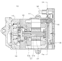
도 1에 도시된 바와 같이 전동 압축기(100)는 대체로 전기력을 역학적 에너지로 변환하여 회전력을 발생시키는 전동 모터부(121), 전동 모터부(121)로부터 회전력을 전달받아 냉매를 압축하는 압축기구부(111) 및 전동 모터부(121)에 전력을 공급하는 제어부(134)를 포함하여 구성된다.As shown in FIG. 1, the
상기 전동 모터부(121)는 모터 하우징(120) 내에 동축으로 배치되고 모터 하우징(120)에 압입되어 고정되는 스테이터(121b) 및 스테이터(121b)의 내부에 회전가능하게 배치되어 스테이터(121b)에 권선된 코일과의 상호작용으로 회전력을 발생하는 로터(121a)를 포함하여 구성되고, 압축기구부(111)는 압축기구부 하우징(110) 내에 배치되어 상기 전동 모터부(121)로부터 회전축(122)을 통해 회전력을 전달받아 회전하도록 구비되는 선회 스크롤 및 상대적으로 고정된 고정 스크롤을 포함하여 구성된다. The
또한, 상기 제어부(134)는 제어부 하우징(130)의 내부에 장착되는 PCB 등 각종 구동회로 및 회로소자들을 포함하며, 전원 케이블(134)로부터 외부 전력을 전달받아 밀폐단자(140)를 통해 모터측 커넥터(141)를 거쳐 전동 모터부(121)로 전력을 공급하도록 구성된다.The control unit 134 includes various driving circuits and circuit elements such as a PCB mounted inside the
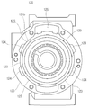
도 2 및 도 3은 도 1의 전동 압축기(100)의 중심축에 수직한 방향(A-A')으로 전동 모터부(121)를 향해 바라본 절단도이다. 2 and 3 are sectional views of the
도 2 및 도 3에 도시된 바와 같이 압축될 냉매가 도시되지 않은 냉매 흡입구를 통해 유입되고, 전동 모터부(121)의 스테이터(121b)의 외주면에 형성된 유로를 통과하여 화살표 방향으로 이동되어 압축기구부(111)로 전달되도록 하기 위해서, 전동 모터부(121)의 스테이터(121b)와 모터 하우징(120) 사이 및 복수의 압입면(123) 사이에는 복수의 냉매 유로(124)가 형성된다.2 and 3, the refrigerant to be compressed flows through a refrigerant suction port (not shown), passes through a flow path formed on the outer peripheral surface of the
이들 유로는 전동 모터부(121)에서 발생하는 열을 흡수하여 전동 모터부(121)의 과열로 인해서 발생하는 전동 압축기(100)의 오작동 문제를 방지하는 역할을 한다.These flow paths absorb heat generated from the
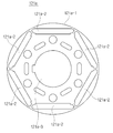
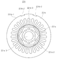
도 4에는 이러한 복수의 냉매 유로 및 복수의 압입면들이 개시되어 있으며, 상세히는 모터 하우징(120)의 내주면에는 적어도 5개의 냉매 유로(124)가 구비되고, 이들 냉매 유로들 사이에는 모터 하우징(120)의 내주면이 스테이터(121b)의 압입면(123)으로 작용하도록 구성된다. 4, at least five
여기서, 도 4의 모터 하우징(120) 상단에 개시된 홀은 전동 모터부(121)의 커넥터(미도시)가 배치되는 공간에 해당된다.4 corresponds to a space in which a connector (not shown) of the
다만, 도 5에 도시된 바와 같이 총 6개의 영구자석이 매립되는 로터(121a)를 구비한 전동 모터(이하, 6극 모터라 함)가 사용되는 경우에 전동 모터는 6의 배수의 주파수를 갖는 진동(이하, 6차수 진동이라 함) 특성을 갖게 된다. However, when an electric motor (hereinafter referred to as a six-pole motor) having a
그러나 상기와 같이 총 5개의 냉매 유로(124)가 구비되는 구성, 즉, 전동 모터부(121)의 압입면(123)이 총 6개소로 구비되는 모터 하우징(120)에 도 5에 도시된 바와 같은 6극 전동 모터가 구비되는 경우에 6극 모터의 의해서 발생하는 6차수의 진동이 총 6개소의 압입면(123)을 통해 모터 하우징(120)에 입력되기 때문에 전동 모터부 및 모터 하우징(120)을 포함하는 전체 전동 압축기(100)에 발생하는 진동은 6차수 진동 특성을 갖게 된다.However, in the
따라서 전동 모터의 로터(121a)에 의해 발생하는 6차수 진동과 전체 전동 압축기(100)의 6차수 진동이 중첩 및 공진되어 진동 및 소음이 증폭되는 문제점이 발생하게 된다.Therefore, there is a problem that the sixth order vibration generated by the
본 발명은 전술한 바와 같은 문제점을 해결하기 위해서 안출된 것으로서, 전동 모터부로부터 발생하는 진동 차수와, 전동 모터부로 인해서 발생하는 압축기 전체의 진동 차수를 서로 상이하게 하여 이들 진동들 사이의 공진을 회피함으로써 감소된 진동 및 소음 구조를 갖는 전동 압축기를 제공하는 것을 목적으로 한다.SUMMARY OF THE INVENTION The present invention has been made in order to solve the above-mentioned problems, and it is an object of the present invention to provide an electric motor, And to provide a motor-driven compressor having a reduced vibration and noise structure.
전술한 과제를 해결하기 위해서, 코일이 권선되는 스테이터(221b, 321b) 및 상기 스테이터(221b, 321b)의 내부에 회전가능하게 구비되며 소정 개수의 영구자석이 매립된 로터(221a, 321a)를 구비한 전동 모터부(221, 321); 및 상기 전동 모터부(221, 321)를 수용하며, 상기 스테이터(221b, 321b)의 외주면을 지지하는 복수의 압입면(223, 323)이 형성된 모터 하우징(220, 320);을 포함하고, 상기 영구자석의 개수와 상기 스테이터의 외주면과 상기 압입면(223, 323)이 서로 접촉하는 접촉면의 개수가 서로 상이한 것을 특징으로 한다.In order to solve the above-described problems, the stator includes a
또한, 본 발명에 따른 전동 압축기는 상기 영구자석의 개수는 상기 접촉면의 개수보다 많은 것을 특징으로 한다.Further, in the motor-driven compressor according to the present invention, the number of the permanent magnets is greater than the number of the contact surfaces.
또한, 본 발명에 따른 전동 압축기는 상기 영구자석의 개수는 6이며, 상기 접촉면의 개수는 5 이하인 것을 특징으로 한다.In the motor-driven compressor according to the present invention, the number of the permanent magnets is 6, and the number of the contact surfaces is 5 or less.
또한, 본 발명에 따른 전동 압축기는 상기 영구자석의 개수는 상기 접촉면의 개수보다 적은 것을 특징으로 한다.Further, in the motor-driven compressor according to the present invention, the number of the permanent magnets is smaller than the number of the contact surfaces.
또한, 본 발명에 따른 전동 압축기는 상기 영구자석의 개수는 6이며, 상기 접촉면의 개수는 7 이상인 것을 특징으로 한다.In the motor-driven compressor according to the present invention, the number of the permanent magnets is 6, and the number of the contact surfaces is 7 or more.
또한, 본 발명에 따른 전동 압축기는 상기 복수의 접촉면들 사이에는 상기 냉매가 통과하는 유로(224, 321b-4)가 형성되는 것을 특징으로 한다.Further, in the motor-driven compressor according to the present invention,
또한, 본 발명에 따른 전동 압축기는 상기 전동 모터부(221, 321)로부터 회전력을 전달받아 냉매를 압축하는 압축기구부를 더 포함하고, 상기 유로(224, 321b-4)를 통과한 냉매는 상기 압축기구부로 전달되는 것을 특징으로 한다.The electric compressor according to the present invention further includes a compression mechanism for compressing the refrigerant by receiving the rotational force from the
또한, 본 발명에 따른 전동 압축기는 상기 유로(224, 321b-4)는 상기 모터 하우징(220, 320)의 내주면에 구비되는 것을 특징으로 한다.The motor-driven compressor according to the present invention is characterized in that the
또한, 본 발명에 따른 전동 압축기는 상기 유로(224, 321b-4)가 상기 스테이터(221b, 321b)의 외주면(221b-1, 321b-1)에 구비되는 것을 특징으로 한다.The electric compressor according to the present invention is characterized in that the
또한, 본 발명에 따른 전동 압축기는 상기 전동 모터부(221, 321)는 상기 모터 하우징(220, 320)에 열간 압입 방식으로 삽입되어 고정되는 것을 특징으로 한다.In the motor-driven compressor according to the present invention, the
본 발명에 따른 전동 압축기는 전동 모터부로부터 발생하는 열을 냉매를 이용하여 효과적으로 배출함으로써 전동 모터부의 안정적인 작동을 보장함과 동시에,전동 모터부, 상세히는 로터의 진동과, 로터에 의해서 진동하게 되는 모터 하우징의 진동의 사이의 공진을 방지함으로써 종래에 비해서 전동 및 소음 특징이 개선되는 효과를 갖는다.INDUSTRIAL APPLICABILITY The motor-driven compressor according to the present invention effectively discharges heat generated from an electric motor part by using a coolant to thereby ensure stable operation of the electric motor part, and also to prevent vibrations of the electric motor part, Thereby preventing resonance between the vibrations of the motor housing, thereby improving the transmission and noise characteristics compared to the prior art.
도 1은 종래의 전동 압축기를 중심축에 나란한 방향으로 절단한 단면도이다.
도 2는 도 1의 전동 압축기의 중심축에 수직한 방향(A-A')으로 전동 모터부를 향해 바라본 절단도이며, 도 3은 도 2의 사시도이다.
도 4는 도 2의 절단도에서 전동 모터부를 생략한 도면이다.
도 5는 6개의 영구자석 모터를 구비한 전동 모터부의 로터를 도시한 도면이다.
도 6은 본 발명의 제1 실시예에 따른 전동 압축기에 구비되는 모터 하우징을 설명하기 위한 도면이다.
도 7은 본 발명의 제1 실시예에 따른 전동 압축기에 구비되는 전동 모터부를 설명하기 위한 도면이다.
도 8은 본 발명의 제2 실시예에 따른 전동 압축기에 구비되는 모터 하우징을 설명하기 위한 도면이다.
도 9는 본 발명의 제2 실시예에 따른 전동 압축기에 구비되는 전동 모터부를 설명하기 위한 도면이다.
도 10은 종래기술에 따른 전동 압축기에서 발생하는 소음 및 본 발명의 실시예에 따른 전동 압축기에서 발생하는 소음을 측정하여 비교 설명하기 위한 도면이다.1 is a cross-sectional view of a conventional motor-driven compressor taken in a direction parallel to a center axis.
FIG. 2 is a sectional view of the motor-driven compressor shown in FIG. 1, taken in a direction (A-A ') perpendicular to the central axis of the motor-driven compressor, and FIG. 3 is a perspective view of FIG.
Fig. 4 is a view showing the electric motor part omitted from the cut-away view of Fig. 2. Fig.
5 is a view showing a rotor of an electric motor unit having six permanent magnet motors.
6 is a view for explaining a motor housing included in the motor-driven compressor according to the first embodiment of the present invention.
7 is a view for explaining an electric motor unit included in the electric compressor according to the first embodiment of the present invention.
8 is a view for explaining a motor housing of an electric compressor according to a second embodiment of the present invention.
9 is a view for explaining an electric motor unit included in the electric compressor according to the second embodiment of the present invention.
10 is a view for comparing and comparing noise generated in the motor compressor according to the related art and noise generated in the motor compressor according to the embodiment of the present invention.
본 발명의 실시를 위한 구체적인 실시예를 첨부된 도면들을 참조하여 설명한다. DETAILED DESCRIPTION OF THE PREFERRED EMBODIMENTS Reference will now be made in detail to embodiments of the present invention, examples of which are illustrated in the accompanying drawings.
본 발명은 다양한 변경을 가할 수 있고 여러 가지 실시예를 가질 수 있는 바, 특정 실시예들을 도면에 예시하고 상세한 설명에 상세하게 설명하고자 한다. 이는 본 발명을 특정한 실시 형태에 대해 한정하려는 의도는 아니며, 본 발명의 사상 및 기술 범위에 포함되는 모든 변경, 균등물 내지 대체물을 포함하는 것으로 이해될 수 있다.While the invention is susceptible to various modifications and alternative forms, specific embodiments thereof are shown by way of example in the drawings and will herein be described in detail. It is to be understood that the present invention is not intended to be limited to the specific embodiments but includes all changes, equivalents, and alternatives included in the spirit and scope of the present invention.
본 발명을 설명함에 있어서 제 1, 제 2 등의 용어는 다양한 구성요소들을 설명하는데 사용될 수 있지만, 상기 구성요소들은 상기 용어들에 의해 한정되지 않을 수 있다. 상기 용어들은 하나의 구성요소를 다른 구성요소로부터 구별하는 목적으로만 된다. 예를 들어, 본 발명의 권리 범위를 벗어나지 않으면서 제 1 구성요소는 제 2 구성요소로 명명될 수 있고, 유사하게 제 2 구성요소도 제 1 구성요소로 명명될 수 있다. In describing the present invention, the terms first, second, etc. may be used to describe various components, but the components may not be limited by the terms. The terms are only for the purpose of distinguishing one component from another. For example, without departing from the scope of the present invention, the first component may be referred to as a second component, and similarly, the second component may also be referred to as a first component.
어떤 구성요소가 다른 구성요소에 "연결되어" 있다거나 "접속되어" 있다고 언급되는 경우는, 그 다른 구성요소에 직접적으로 연결되어 있거나 또는 접속되어 있을 수도 있지만, 중간에 다른 구성요소가 존재할 수도 있다고 이해될 수 있다. 반면에, 어떤 구성요소가 다른 구성요소에 "직접 연결되어" 있다거나 "직접 접속되어" 있다고 언급된 때에는, 중간에 다른 구성요소가 존재하지 않는 것으로 이해될 수 있다. When an element is referred to as being "connected" or "connected" to another element, it may be directly connected or connected to the other element, but other elements may be present in between Can be understood. On the other hand, when it is mentioned that an element is "directly connected" or "directly connected" to another element, it can be understood that no other element exists in between.
본 명세서에서 사용한 용어는 단지 특정한 실시예를 설명하기 위해 사용된 것으로, 본 발명을 한정하려는 의도가 아니다. 단수의 표현은 문맥상 명백하게 다르게 뜻하지 않는 한, 복수의 표현을 포함할 수 있다. The terminology used herein is for the purpose of describing particular embodiments only and is not intended to be limiting of the invention. The singular expressions may include plural expressions unless the context clearly dictates otherwise.
본 명세서에서, "포함하다" 또는 "구비하다" 등의 용어는 명세서상에 기재된 특징, 숫자, 단계, 동작, 구성요소, 부품 또는 이들을 조합한 것이 존재함을 지정하려는 것으로서, 하나 또는 그 이상의 다른 특징들이나 숫자, 단계, 동작, 구성요소, 부품 또는 이들을 조합한 것들의 존재 또는 부가 가능성을 미리 배제하지 않는 것으로 이해될 수 있다. In this specification, the terms "comprise", "comprising", and the like are used interchangeably to designate the presence of stated features, integers, steps, operations, elements, components, or combinations thereof, But do not preclude the presence or addition of features, numbers, steps, operations, components, parts, or combinations thereof.
또한, 다르게 정의되지 않는 한, 기술적이거나 과학적인 용어를 포함해서 본 명세서에서 사용되는 모든 용어들은 본 발명이 속하는 기술 분야에서 통상의 지식을 가진 자에 의해 일반적으로 이해되는 것과 동일한 의미를 가질 수 있다. 일반적으로 사용되는 사전에 정의되어 있는 것과 같은 용어들은 관련 기술의 문맥상 가지는 의미와 일치하는 의미를 가지는 것으로 해석될 수 있으며, 본 명세서에서 명백하게 정의하지 않는 한, 이상적이거나 과도하게 형식적인 의미로 해석되지 않을 수 있다.Also, unless otherwise defined, all terms used herein, including technical or scientific terms, may have the same meaning as commonly understood by one of ordinary skill in the art to which this invention belongs . Terms such as those defined in commonly used dictionaries can be interpreted as having a meaning consistent with the meaning in the context of the related art and, unless explicitly defined herein, are interpreted in an ideal or overly formal sense .
또한, 이하의 실시예는 당 업계에서 평균적인 지식을 가진 자에게 보다 명확하게 설명하기 위해서 제공되는 것으로서, 도면에서의 요소들의 형상 및 크기 등은 보다 명확한 설명을 위해 과장될 수 있다.
In addition, the following embodiments are provided so as to explain the invention more clearly to those skilled in the art. The shapes and sizes of the elements in the drawings may be exaggerated for clarity.
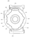
도 6 및 도 7은 본 발명의 제1 실시예에 따른 전동 압축기에 구비되는 모터 하우징(220) 및 전동 모터부(221)를 설명하기 위한 도면이다. FIGS. 6 and 7 are views for explaining the
도 6 및 도 7을 참조하면, 본 발명의 제1 실시예에 따른 전동 압축기는 코일이 권선되는 스테이터(221b) 및 상기 스테이터(221b)의 내부에 회전가능하게 구비되며 소정 개수의 영구자석이 매립된 로터(221a)를 구비한 전동 모터부(221); 및 상기 전동 모터부(221)를 수용하며, 상기 스테이터(221b)의 외주면을 지지하는 압입면(223)이 형성된 모터 하우징(220);을 포함하고, 상기 압입면(223)은 복수 개로 구비되며, 이들 복수의 압입면(223) 사이에는 상기 냉매가 통과하는 유로(224)가 형성되도록 구성되고, 상기 유로(224)는 모터 하우징(220)에 형성되도록 구성된다.6 and 7, the motor-driven compressor according to the first embodiment of the present invention includes a
즉, 스테이터(221b)를 반경방향으로 지지하는 모터 하우징(220)의 내주면이 복수의 압입면(223) 및 복수의 유로(224)로 분할되도록 구성되며, 상기 압입면(223)은 후술하는 스테이터의 외주면과의 접촉면으로 작용한다.That is, the inner circumferential surface of the
나아가 상기 영구자석의 개수와 상기 복수의 접촉면의 개수가 서로 상이하도록 구성될 수 있으며, 바람직하게는 영구자석의 개수가 상기 접촉면의 개수보다 많거나 적게 되도록 구성된다.Furthermore, the number of the permanent magnets may be different from the number of the plurality of contact surfaces. Preferably, the number of the permanent magnets is larger or smaller than the number of the contact surfaces.
즉, 전동 모터부(221)가 압입되는 지지되는 접촉면의 개수와 전동 모터부(221)의 개수를 서로 다르게 구성함으로써 종래 전동 압축기(100)에서 발생하는 진동 및 소음을 효과적으로 감소시킬 수 있게 된다.That is, the vibration and noise generated in the conventional motor-driven
이를 좀 더 상세히 설명하면 다음과 같다.This will be described in more detail as follows.
본 발명에 따른 전동 압축기의 모터 하우징(220)은 금속 재질, 바람직하게는 알루미늄 등과 같이 가벼우면서도 일정한 강성을 갖는 금속으로 형성되며, 내부에는 전동 모터부(221)를 밀폐식으로 수용하기 위한 수용 공간이 형성된다.The
또한, 상기 모터 하우징(220)의 내주면에는 도 7에 도시된 전동 모터부(221), 정확히는 스테이터(221b)가 압입되어 고정되는 동시에 스테이터(221b)를 원주방향으로 지지하는 압입면(223)이 원주 방향으로 복수 개소에 구비된다.7 is press-fitted and fixed to the inner circumferential surface of the
이에 한정되는 것은 아니지만 본 발명에 따른 전동 모터부(221)는 스테이터(221b)의 외주면이 상기 모터 하우징(220)의 내주면, 즉 압입면(223)에 열간 압입 방식으로 삽입되어 고정되도록 구성된다.Although not limited thereto, the
한편, 모터 하우징(220)의 내주면에 구비된 복수의 압입면(223) 사이에는 하우징의 길이방향으로 냉매가 통과하는 유로(224)가 형성되며, 바람직하게는 상기 유로(224)는 모터 하우징(220)의 내주면에 복수 개소에 구비된다.A
이들 유로(224)는 압축기구부(미도시)로 전달될 냉매가 통과하는 공간으로서 유입된 냉매는 전동 모터부(221)로부터 발생하는 열을 스테이터(221b)의 외주면으로부터 효과적으로 흡수하여 전동 모터부(221)를 냉각하고 전동 모터부(221)의 과열을 방지하는 역할을 한다.The
즉, 전동 모터부(221)는 작동 시 상당한 수준의 발열이 발생하기 때문에 이러한 발열에 의해서 전동 모터부(221)의 오작동이 발생할 위험이 있다.That is, since the
따라서 전동 압축기로 유입된 냉매를 통해서 전동 모터부(221)에서 발생하는 열을 흡수하도록 구성함으로써 전동 모터부(221)의 과열을 방지할 수 있게 된다. Therefore, the heat generated in the
전동 모터부(221)를 통과한 냉매는 전동 압축기의 축방향으로 이동되고, 압축기구부로 전달되어 최종적으로 압축되어 압축기 외부로 토출된다.The refrigerant passing through the
한편, 본 발명에 따른 전동 압축기의 전동 모터부(221)는 내부에 코일이 권선되며 모터 하우징(220)에 압입되어 고정되는 스테이터(221b) 및 상기 스테이터(221b)의 내부에 회전가능하게 구비되며 복수 개의 영구자석이 매립되는 로터(221a)를 구비한다. Meanwhile, the
스테이터(221b)는 대략의 원통 형상을 갖도록 구성되며, 내주면에는 스테이터의 길이방향으로 연장되어 코일이 감기게 되는 복수의 권선티스(221b-3)가 형성되며, 상기 권선티스(221b-3)에는 코일이 상기 권선티스(221b-3)를 따라 그 연장방향으로 권선되고, 중앙 관통홀에는 로터(221a)가 회전가능하게 구비된다.A plurality of winding
한편, 도 7에 도시된 스테이터(221b)의 외주면은 대략 원통형상으로 굴곡이 없는 평탄면으로 형성되는 것으로 도시되어 있으나, 스테이터(221b)의 외주면을 통과하는 냉매로의 열전달 효율을 높이기 위해 상기 유로(224)에 대응되는 위치에 일정한 함몰부(미도시)가 구비될 수도 있으며, 이러한 함몰부는 스테이터(221b)가 충분한 강성을 가질 수 있는 구조로 형성되는 경우에 구비되는 것이 바람직하다.The outer surface of the
또한, 스테이터(221b)의 외주면에는 상기 코일에 전력을 공급하게 위한 커넥터(미도시)가 설치되는 체결슬롯(221b-2)이 더 구비될 수 있다.The
로터(221a)는 스테이터(221b)에 권선된 코일에 의해 발생되는 전기력과 상호작용하도록 복수 개의 영구자석이 길이방향으로 매립되며, 도 7에는 예시적으로 영구자석이 총 6개 매립될 수 있도록 총 6개의 삽입공(221a-2)이 구비된 로터(221a)가 도시되어 있지만, 본 발명은 이에 한정되는 것은 아니며, 다양한 개수의 영구자석을 구비한 로터(221a)로 본 발명의 범위에 속하는 것으로 볼 것이다. A plurality of permanent magnets are embedded in the longitudinal direction so that the
이하에서는 총 6개의 영구자석을 포함하는 전동 모터(6극 모터)를 기준으로 설명한다.Hereinafter, an electric motor (six-pole motor) including six permanent magnets will be used as a reference.
도 7과 같은 6극의 전동 모터부(221)가 구비되는 되는 경우에 전동 모터부(221)의 작동 시 전술한 바와 같이 로터(221a)에 의해서 6차수의 진동이 발생하며, 발생된 진동은 스테이터(221b)를 통해서 복수의 접촉면을 거쳐 모터 하우징(220)으로 전달된다.7, when the
이때, 모터 하우징(220)의 내주면과 스테이터(221b) 사이의 접촉면의 개수가 6이 아닌 수(5 또는 7)로 설정하여 모터 하우징(220) 및 전동 모터부(221) 전체 진동 특성이 6차수가 되지 않도록 하여, 전동 모터부(221)로부터 발생하는 진동 차수와 모터 하우징(220) 전체의 진동 차수가 서로 상이하게 구성됨으로써 이들 진동 사이의 공진을 회피할 수 있게 된다.At this time, the number of contact surfaces between the inner circumferential surface of the
즉, 전동 모터부(221)의 진동에 의한 모터 하우징(220)의 진동 특성이 적어도 6차수가 되지 않도록 구성함으로써 전동 모터부(221)의 진동과, 이로 인해 발생하는 모터 하우징(220)의 진동 사이의 공진을 회피하도록 구성하는 것이다.That is, the vibration characteristics of the
도 6에 도시된 바와 같이 제1 실시예는 예시적으로 모터 하우징(220)의 내주면에 총 5개의 압입면(223)이 구비되도록 하여 접촉면이 총 5개로 구성되어 있지만, 그 이하의 접촉면의 개수를 갖거나, 총 7개 이상의 접촉면을 갖도록 구성하는 것도 가능하며, 이들 모두는 본 발명의 범위에 당연히 속하게 된다.As shown in FIG. 6, in the first embodiment, a total of five contact surfaces are provided so that a total of five
도 8 및 도 9는 본 발명의 제2 실시예에 따른 전동 압축기에 구비되는 모터 하우징(320) 및 전동 모터부(321)를 설명하기 위한 도면이다.8 and 9 are views for explaining a
도 8 및 도 9를 참조하면, 본 발명의 제2 실시예에 따른 전동 압축기는, 제1 실시예와 유사하게 코일이 권선되는 스테이터(321b) 및 상기 스테이터(321b)의 내부에 회전가능하게 구비되며 소정 개수의 영구자석이 매립된 로터(321a)를 구비한 전동 모터부(321); 및 상기 전동 모터부(321)를 수용하며, 상기 스테이터(321b)의 외주면을 지지하는 압입면(323)이 형성된 모터 하우징(320);을 포함하고, 상기 스테이터(321b)의 외주면에는 상기 냉매가 통과하는 복수의 유로(321b-4)가 형성되도록 구성된다.8 and 9, an electric compressor according to a second embodiment of the present invention includes a
즉, 제1 실시예와는 달리 제2 실시예는 냉매가 통과하는 유로가 모터 하우징(320)의 내주면이 아닌 전동 모터부(321)의 스테이터(321b)의 외주면에 함몰부(321b-4)의 형태로 구비되도록 구성된다.That is, unlike the first embodiment, the second embodiment differs from the first embodiment in that the flow passage through which the refrigerant passes is not the inner peripheral surface of the
이러한 실시예는 모터 하우징(320)의 벽 두께가 유로를 형성하기에 비교적 부족한 경우에 바람직하다. This embodiment is preferable when the wall thickness of the
다만, 모터 하우징(320)의 강성에 영향을 주지 않는 범위 내에서 모터 하우징(320)의 내주면에는 상기 함몰부(321b-4)에 대응되는 위치에 일정한 유로(미도시)가 형성될 수도 있다However, a constant flow passage (not shown) may be formed on the inner circumferential surface of the
한편, 상기와 같이 스테이터(321b)의 외주면에 냉매의 유로가 형성되는 경우에 로터(321a)로부터 스테이터(321b)를 거쳐 모터 하우징(320)의 내주면으로 입력되는 진동의 차수는 스테이터(321b)의 외주면의 함몰부(321b-4)의 개수 및 접촉면(321b-1)의 개수로 결정된다.The degree of vibration input from the
도 9에 도시된 바와 같이 6극 모터가 사용되는 경우에 공진으로 인한 진동 및 소음을 방지하기 위해서, 상기 접촉면(321b-1)의 개수는 6이 되지 않도록 구성된다.As shown in FIG. 9, in order to prevent vibration and noise due to resonance when a six-pole motor is used, the number of contact surfaces 321b-1 is not set to six.
이를 위해 도 9에는 접촉면(321b-1)의 개수가 8이며, 냉매가 통과하는 함몰부(321b-4)의 개수가 7이 되는 스테이터(321b)가 도시되어 있다.9 shows a
다만, 제1 실시예와 마찬가지로 이러한 접촉면(321b-1)의 개수 및 함몰부(321b-4)는 조절이 가능하며, 접촉면(321b-1)의 개수와 로터(321a)에 매립되는 영구자석의 수가 서로 다르게 설정되는 구성은 모두 본 발명의 범위에 속함은 당연하다.Like the first embodiment, the number of the contact surfaces 321b-1 and the
기타 모터 하우징(320) 및 전동 모터부(321)의 다른 상세 구성은 제1 실시예와 동일하며, 중복되는 내용은 생략하기로 한다.Other detailed configurations of the
도 10은 종래기술에 따른 전동 압축기에서 발생하는 소음 및 본 발명의 실시예에 따른 전동 압축기에서 발생하는 소음을 측정하여 비교 설명하기 위한 도면이다.10 is a view for comparing and comparing noise generated in the motor compressor according to the related art and noise generated in the motor compressor according to the embodiment of the present invention.
도 10을 참조하면, 먼저 종래 기술에 따라 6극의 전동 모터부 및 6개의 압입면이 형성된 모터 하우징을 대상으로 전동 모터의 회전수에 따른 소음량에 대한 측정 결과 선도(B1) 및 본 발명(특히, 제1 실시예)에 따라 6극의 전동 모터부 및 5개의 접촉면이 형성된 모터 하우징을 대상으로 전동 모터의 회전수에 따른 소음량에 대한 측정 결과 선도(B2)가 도시되어 있다.Referring to FIG. 10, the results of the measurement of the amount of noise according to the number of revolutions of the electric motor (B1) and the present invention Particularly, a measurement result B2 of a noise amount according to the number of revolutions of the electric motor is shown for a motor housing having six electric motor parts and five contact surfaces according to the first embodiment.
이 경우에 가로축은 로터의 회전수(Hz)에 해당하며, 세로축은 해당 회전수로 발생하는 전동 압축기 전체의 소음량(dB)를 나타낸다.In this case, the horizontal axis corresponds to the number of revolutions (Hz) of the rotor, and the vertical axis denotes the noise amount (dB) of the entire motor compressor generated at the corresponding number of revolutions.
해당 측정 결과를 분석하면, 본 발명에 따른 전동 압축기의 소음량이 종래 압축기의 소음량보다 낮음을 알 수 있으며, 특히 고주파 대역(1500Hz 이상)에서의 소음량이 확연히 차이가 남을 확인할 수 있었으며, 본 발명이 종래 기술에 비해서 소음 저감 효과가 우수함이 확인할 수 있었다.It can be seen from the analysis of the measurement results that the noise level of the electric compressor according to the present invention is lower than the noise level of the conventional compressor and the noise level at the high frequency band (1500 Hz or more) It was confirmed that the noise reduction effect is superior to that of the prior art.
이와 같이, 상술한 본 발명의 기술적 구성은 본 발명이 속하는 기술분야의 당업자가 본 발명의 그 기술적 사상이나 필수적 특징을 변경하지 않고서 다른 구체적인 형태로 실시될 수 있다는 것을 이해할 수 있을 것이다.As described above, it is to be understood that the technical structure of the present invention can be embodied in other specific forms without departing from the spirit and essential characteristics of the present invention.
그러므로 이상에서 기술한 실시예들은 모든 면에서 예시적인 것이며 한정적인 것이 아닌 것으로서 이해되어야 하고, 본 발명의 범위는 전술한 상세한 설명보다는 후술하는 특허청구범위에 의하여 나타내어지며, 특허청구범위의 의미 및 범위 그리고 그 등가개념으로부터 도출되는 모든 변경 또는 변형된 형태가 본 발명의 범위에 포함되는 것으로 해석되어야 할 것이다.It should be understood, therefore, that the embodiments described above are to be considered in all respects as illustrative and not restrictive, the scope of the invention being indicated by the appended claims rather than the foregoing description, And all changes or modifications derived from the equivalents thereof should be construed as being included within the scope of the present invention.
Claims (10)
코일이 권선되는 스테이터(221b, 321b) 및 상기 스테이터(221b, 321b)의 내부에 회전가능하게 구비되며 소정 개수의 영구자석이 매립된 로터(221a, 321a)를 구비한 전동 모터부(221, 321); 및
상기 전동 모터부(221, 321)를 수용하며, 상기 스테이터(221b, 321b)의 외주면을 지지하는 압입면(223, 323)이 형성된 모터 하우징(220, 320);
을 포함하고,
상기 영구자석의 개수와 상기 스테이터의 외주면과 상기 압입면(223, 323)이 서로 접촉하는 접촉면의 개수가 서로 상이한 것을 특징으로 하는 전동 압축기.An electric compressor for compressing refrigerant,
And electric motors 221 and 321b provided with rotors 221a and 321a which are rotatably disposed in the stator 221b and 321b and in which a predetermined number of permanent magnets are embedded, ); And
Motor housings (220, 320) housing the electric motor portions (221, 321) and having press-in surfaces (223, 323) for supporting the outer circumferential surfaces of the stator (221b, 321b);
/ RTI >
Wherein the number of the permanent magnets, the outer circumferential surface of the stator, and the number of contact surfaces where the press-in surfaces (223, 323) contact each other are different from each other.
상기 영구자석의 개수는 상기 접촉면의 개수보다 많은 것을 특징으로 하는 전동 압축기.The method according to claim 1,
Wherein the number of the permanent magnets is greater than the number of the contact surfaces.
상기 영구자석의 개수는 6이며, 상기 접촉면의 개수는 5 이하인 것을 특징으로 하는 전동 압축기.5. The method of claim 4,
Wherein the number of the permanent magnets is 6, and the number of the contact surfaces is 5 or less.
상기 영구자석의 개수는 상기 접촉면의 개수보다 적은 것을 특징으로 하는 전동 압축기.The method according to claim 1,
Wherein the number of the permanent magnets is smaller than the number of the contact surfaces.
상기 영구자석의 개수는 6이며, 상기 접촉면의 개수는 7 이상인 것을 특징으로 하는 전동 압축기.5. The method of claim 4,
Wherein the number of the permanent magnets is 6, and the number of the contact surfaces is 7 or more.
상기 복수의 접촉면들 사이에는 상기 냉매가 통과하는 유로(224, 321b-4)가 형성되는 것을 특징으로 하는 전동 압축기.The method according to claim 1,
And flow paths (224, 321b-4) through which the refrigerant passes are formed between the plurality of contact surfaces.
상기 전동 모터부(221, 321)로부터 회전력을 전달받아 냉매를 압축하는 압축기구부를 더 포함하고,
상기 유로(224, 321b-4)를 통과한 냉매는 상기 압축기구부로 전달되는 것을 특징으로 하는 전동 압축기.The method according to claim 6,
Further comprising a compression mechanism for receiving the rotational force from the electric motor units (221, 321) and compressing the refrigerant,
And the refrigerant having passed through the flow paths (224, 321b-4) is transmitted to the compression mechanism.
상기 유로(224, 321b-4)는 상기 모터 하우징(220, 320)의 내주면에 구비되는 것을 특징으로 하는 전동 압축기.The method according to claim 6,
Wherein the oil passages (224, 321b-4) are provided on an inner peripheral surface of the motor housing (220, 320).
상기 유로(224, 321b-4)는 상기 스테이터(221b, 321b)의 외주면(221b-1, 321b-1)에 구비되는 것을 특징으로 하는 전동 압축기.The method according to claim 6,
Wherein the flow paths 224 and 321b-4 are provided on the outer peripheral surfaces 221b-1 and 321b-1 of the stator 221b and 321b, respectively.
상기 전동 모터부(221, 321)는 상기 모터 하우징(220, 320)에 열간 압입 방식으로 삽입되어 고정되는 것을 특징으로 하는 전동 압축기.The method according to claim 1,
Wherein the electric motor units (221, 321) are inserted and fixed to the motor housings (220, 320) by a hot pressing method.
Priority Applications (1)
| Application Number | Priority Date | Filing Date | Title |
|---|---|---|---|
| KR20130112591A KR20150033072A (en) | 2013-09-23 | 2013-09-23 | Electric compressor |
Applications Claiming Priority (1)
| Application Number | Priority Date | Filing Date | Title |
|---|---|---|---|
| KR20130112591A KR20150033072A (en) | 2013-09-23 | 2013-09-23 | Electric compressor |
Publications (1)
| Publication Number | Publication Date |
|---|---|
| KR20150033072A true KR20150033072A (en) | 2015-04-01 |
Family
ID=53030502
Family Applications (1)
| Application Number | Title | Priority Date | Filing Date |
|---|---|---|---|
| KR20130112591A KR20150033072A (en) | 2013-09-23 | 2013-09-23 | Electric compressor |
Country Status (1)
| Country | Link |
|---|---|
| KR (1) | KR20150033072A (en) |
Cited By (1)
| Publication number | Priority date | Publication date | Assignee | Title |
|---|---|---|---|---|
| WO2020153682A1 (en) * | 2019-01-25 | 2020-07-30 | 한온시스템 주식회사 | Electric compressor |
-
2013
- 2013-09-23 KR KR20130112591A patent/KR20150033072A/en not_active Application Discontinuation
Cited By (1)
| Publication number | Priority date | Publication date | Assignee | Title |
|---|---|---|---|---|
| WO2020153682A1 (en) * | 2019-01-25 | 2020-07-30 | 한온시스템 주식회사 | Electric compressor |
Similar Documents
| Publication | Publication Date | Title |
|---|---|---|
| US6836051B2 (en) | Motor | |
| US20150056086A1 (en) | Electric compressor | |
| EP2903141A2 (en) | Motor | |
| JP5698007B2 (en) | Electric compressor | |
| JP2010110142A (en) | Permanent magnet type rotary electric machine and compressor using the same | |
| US10707715B2 (en) | Motor-driven compressor | |
| JP6766666B2 (en) | Electric compressor | |
| EP3154175B1 (en) | Electric motor and compressor having the same | |
| CN109923757B (en) | Permanent magnet type rotating electrical machine and compressor using the same | |
| WO2019073509A1 (en) | Stator, electric motor, compressor, air conditioning device, and stator manufacturing method | |
| JP5945194B2 (en) | Electric compressor | |
| US20140377095A1 (en) | Motor-driven compressor | |
| KR101591027B1 (en) | Motor-driven compressor | |
| KR20150033072A (en) | Electric compressor | |
| JPWO2016199884A1 (en) | Electric compressor | |
| JP2010093910A (en) | Permanent magnet type rotating electric machine and compressor using the same | |
| US20160006316A1 (en) | Radially offset motor control housing | |
| KR20200063728A (en) | ElECTRIC COMPRESSOR | |
| JP2022156947A (en) | Fluid machine | |
| WO2023190366A1 (en) | Electric compressor | |
| WO2019146030A1 (en) | Permanent magnet dynamo-electric machine, and compressor using same | |
| JP6492446B2 (en) | Terminal and compressor with terminal | |
| US20210017992A1 (en) | Electric compressor | |
| KR20190135277A (en) | Electric compressor | |
| JP2004297936A (en) | Motor |
Legal Events
| Date | Code | Title | Description |
|---|---|---|---|
| E902 | Notification of reason for refusal | ||
| E601 | Decision to refuse application |