KR20150018547A - Vanadium flow cell - Google Patents
Vanadium flow cell Download PDFInfo
- Publication number
- KR20150018547A KR20150018547A KR1020147034241A KR20147034241A KR20150018547A KR 20150018547 A KR20150018547 A KR 20150018547A KR 1020147034241 A KR1020147034241 A KR 1020147034241A KR 20147034241 A KR20147034241 A KR 20147034241A KR 20150018547 A KR20150018547 A KR 20150018547A
- Authority
- KR
- South Korea
- Prior art keywords
- flow
- electrolyte
- state
- stack
- end plate
- Prior art date
Links
Images


Classifications
-
- H—ELECTRICITY
- H01—ELECTRIC ELEMENTS
- H01M—PROCESSES OR MEANS, e.g. BATTERIES, FOR THE DIRECT CONVERSION OF CHEMICAL ENERGY INTO ELECTRICAL ENERGY
- H01M8/00—Fuel cells; Manufacture thereof
- H01M8/18—Regenerative fuel cells, e.g. redox flow batteries or secondary fuel cells
- H01M8/184—Regeneration by electrochemical means
- H01M8/188—Regeneration by electrochemical means by recharging of redox couples containing fluids; Redox flow type batteries
-
- H—ELECTRICITY
- H01—ELECTRIC ELEMENTS
- H01M—PROCESSES OR MEANS, e.g. BATTERIES, FOR THE DIRECT CONVERSION OF CHEMICAL ENERGY INTO ELECTRICAL ENERGY
- H01M8/00—Fuel cells; Manufacture thereof
- H01M8/18—Regenerative fuel cells, e.g. redox flow batteries or secondary fuel cells
-
- H—ELECTRICITY
- H01—ELECTRIC ELEMENTS
- H01M—PROCESSES OR MEANS, e.g. BATTERIES, FOR THE DIRECT CONVERSION OF CHEMICAL ENERGY INTO ELECTRICAL ENERGY
- H01M8/00—Fuel cells; Manufacture thereof
- H01M8/02—Details
- H01M8/0271—Sealing or supporting means around electrodes, matrices or membranes
- H01M8/0273—Sealing or supporting means around electrodes, matrices or membranes with sealing or supporting means in the form of a frame
-
- H—ELECTRICITY
- H01—ELECTRIC ELEMENTS
- H01M—PROCESSES OR MEANS, e.g. BATTERIES, FOR THE DIRECT CONVERSION OF CHEMICAL ENERGY INTO ELECTRICAL ENERGY
- H01M8/00—Fuel cells; Manufacture thereof
- H01M8/04—Auxiliary arrangements, e.g. for control of pressure or for circulation of fluids
- H01M8/04298—Processes for controlling fuel cells or fuel cell systems
- H01M8/04992—Processes for controlling fuel cells or fuel cell systems characterised by the implementation of mathematical or computational algorithms, e.g. feedback control loops, fuzzy logic, neural networks or artificial intelligence
-
- H—ELECTRICITY
- H01—ELECTRIC ELEMENTS
- H01M—PROCESSES OR MEANS, e.g. BATTERIES, FOR THE DIRECT CONVERSION OF CHEMICAL ENERGY INTO ELECTRICAL ENERGY
- H01M8/00—Fuel cells; Manufacture thereof
- H01M8/02—Details
-
- H—ELECTRICITY
- H01—ELECTRIC ELEMENTS
- H01M—PROCESSES OR MEANS, e.g. BATTERIES, FOR THE DIRECT CONVERSION OF CHEMICAL ENERGY INTO ELECTRICAL ENERGY
- H01M8/00—Fuel cells; Manufacture thereof
- H01M8/04—Auxiliary arrangements, e.g. for control of pressure or for circulation of fluids
-
- H—ELECTRICITY
- H01—ELECTRIC ELEMENTS
- H01M—PROCESSES OR MEANS, e.g. BATTERIES, FOR THE DIRECT CONVERSION OF CHEMICAL ENERGY INTO ELECTRICAL ENERGY
- H01M8/00—Fuel cells; Manufacture thereof
- H01M8/04—Auxiliary arrangements, e.g. for control of pressure or for circulation of fluids
- H01M8/04007—Auxiliary arrangements, e.g. for control of pressure or for circulation of fluids related to heat exchange
- H01M8/04067—Heat exchange or temperature measuring elements, thermal insulation, e.g. heat pipes, heat pumps, fins
- H01M8/04074—Heat exchange unit structures specially adapted for fuel cell
-
- H—ELECTRICITY
- H01—ELECTRIC ELEMENTS
- H01M—PROCESSES OR MEANS, e.g. BATTERIES, FOR THE DIRECT CONVERSION OF CHEMICAL ENERGY INTO ELECTRICAL ENERGY
- H01M8/00—Fuel cells; Manufacture thereof
- H01M8/04—Auxiliary arrangements, e.g. for control of pressure or for circulation of fluids
- H01M8/04223—Auxiliary arrangements, e.g. for control of pressure or for circulation of fluids during start-up or shut-down; Depolarisation or activation, e.g. purging; Means for short-circuiting defective fuel cells
- H01M8/04228—Auxiliary arrangements, e.g. for control of pressure or for circulation of fluids during start-up or shut-down; Depolarisation or activation, e.g. purging; Means for short-circuiting defective fuel cells during shut-down
-
- H—ELECTRICITY
- H01—ELECTRIC ELEMENTS
- H01M—PROCESSES OR MEANS, e.g. BATTERIES, FOR THE DIRECT CONVERSION OF CHEMICAL ENERGY INTO ELECTRICAL ENERGY
- H01M8/00—Fuel cells; Manufacture thereof
- H01M8/20—Indirect fuel cells, e.g. fuel cells with redox couple being irreversible
-
- H—ELECTRICITY
- H01—ELECTRIC ELEMENTS
- H01M—PROCESSES OR MEANS, e.g. BATTERIES, FOR THE DIRECT CONVERSION OF CHEMICAL ENERGY INTO ELECTRICAL ENERGY
- H01M8/00—Fuel cells; Manufacture thereof
- H01M8/24—Grouping of fuel cells, e.g. stacking of fuel cells
-
- H—ELECTRICITY
- H01—ELECTRIC ELEMENTS
- H01M—PROCESSES OR MEANS, e.g. BATTERIES, FOR THE DIRECT CONVERSION OF CHEMICAL ENERGY INTO ELECTRICAL ENERGY
- H01M8/00—Fuel cells; Manufacture thereof
- H01M8/24—Grouping of fuel cells, e.g. stacking of fuel cells
- H01M8/2465—Details of groupings of fuel cells
- H01M8/2483—Details of groupings of fuel cells characterised by internal manifolds
-
- H—ELECTRICITY
- H01—ELECTRIC ELEMENTS
- H01M—PROCESSES OR MEANS, e.g. BATTERIES, FOR THE DIRECT CONVERSION OF CHEMICAL ENERGY INTO ELECTRICAL ENERGY
- H01M8/00—Fuel cells; Manufacture thereof
- H01M8/04—Auxiliary arrangements, e.g. for control of pressure or for circulation of fluids
- H01M8/04298—Processes for controlling fuel cells or fuel cell systems
- H01M8/043—Processes for controlling fuel cells or fuel cell systems applied during specific periods
- H01M8/04303—Processes for controlling fuel cells or fuel cell systems applied during specific periods applied during shut-down
-
- Y—GENERAL TAGGING OF NEW TECHNOLOGICAL DEVELOPMENTS; GENERAL TAGGING OF CROSS-SECTIONAL TECHNOLOGIES SPANNING OVER SEVERAL SECTIONS OF THE IPC; TECHNICAL SUBJECTS COVERED BY FORMER USPC CROSS-REFERENCE ART COLLECTIONS [XRACs] AND DIGESTS
- Y02—TECHNOLOGIES OR APPLICATIONS FOR MITIGATION OR ADAPTATION AGAINST CLIMATE CHANGE
- Y02E—REDUCTION OF GREENHOUSE GAS [GHG] EMISSIONS, RELATED TO ENERGY GENERATION, TRANSMISSION OR DISTRIBUTION
- Y02E60/00—Enabling technologies; Technologies with a potential or indirect contribution to GHG emissions mitigation
- Y02E60/30—Hydrogen technology
- Y02E60/50—Fuel cells
Landscapes
- Engineering & Computer Science (AREA)
- General Chemical & Material Sciences (AREA)
- Sustainable Development (AREA)
- Sustainable Energy (AREA)
- Manufacturing & Machinery (AREA)
- Chemical & Material Sciences (AREA)
- Chemical Kinetics & Catalysis (AREA)
- Electrochemistry (AREA)
- Life Sciences & Earth Sciences (AREA)
- Automation & Control Theory (AREA)
- Artificial Intelligence (AREA)
- Computing Systems (AREA)
- Evolutionary Computation (AREA)
- Fuzzy Systems (AREA)
- Medical Informatics (AREA)
- Software Systems (AREA)
- Theoretical Computer Science (AREA)
- Health & Medical Sciences (AREA)
- Fuel Cell (AREA)
Abstract
바나듐 화학물질을 이용하는 플로우 셀 시스템이 제공된다. 플로우 셀 시스템은 스택, 전해질 열 교환기들, 및 상태 머신을 실행시키는 제어기를 포함한다. 엔드 플레이트 구조를 갖는 플로우 셀 시스템용 스택은 전도 플레이트 및 유체 매니폴드들을 포함하는 가스켓 프레임을 포함한다. 전해질 열 교환기는 플로우 필드 매체; 및 플로우 필드 매체를 분리하는 열 전달 시트들을 포함하고, 여기서 전해질 및 열 교환 유체가 전해질 열 교환기를 통해 유동될 수 있다. 본 발명에 따른 제어기는 초기화 상태; 충전 상태; 방전 상태; 플로트 상태; 하이버네이트 상태; 및 셧다운 상태를 포함할 수 있다.A flow cell system using vanadium chemistry is provided. The flow cell system includes a stack, electrolyte heat exchangers, and a controller for executing the state machine. A stack for a flow cell system having an endplate structure includes a gasket frame including a conduction plate and fluid manifolds. The electrolyte heat exchanger is a flow field medium; And heat transfer sheets separating the flow field medium, wherein the electrolyte and the heat exchange fluid can flow through the electrolyte heat exchanger. The controller according to the present invention comprises: an initialization state; Charge status; Discharge state; Float state; Hibernate status; And a shutdown state.
Description
관련 출원들에 대한 참조Reference to Related Applications
본 출원은 2012년 5월 10일에 출원된 미국 가출원 제 61/645,495 호, 및 2013년 3월 15일에 출원된 미국 정규출원 제 13/842,446 호에 대해 우선권을 주장하며, 이들 출원의 전체 내용들은 그 전체가 참조로서 여기에 포함된다.This application claims priority to U.S. Provisional Application No. 61 / 645,495, filed May 10, 2012, and U.S. Serial No. 13 / 842,446, filed on March 15, 2013, Are hereby incorporated by reference in their entirety.
본 발명의 분야Field of the Invention
본 개시물은 플로우 (flow) 셀 시스템, 특히 바나듐계 화학물질을 사용하는 플로우 셀 시스템에 관한 것이다.The present disclosure relates to flow cell systems, and more particularly to flow cell systems using vanadium based chemicals.
신규하고 혁신적인 전기 전력 저장 시스템들에 대한 요구가 증가하고 있다. 레독스 (redox) 플로우 셀 배터리들은 이러한 에너지 저장을 위한 매력적인 수단이 되고 있다. 소정 애플리케이션들에서, 레독스 플로우 셀 배터리는 하나 이상의 레독스 플로우 셀들을 포함할 수도 있다. 레독스 플로우 셀들의 각각은 분리된 하프 셀 (half-cell) 컴파트먼트들에 배치된 양극 및 음극 전극을 포함할 수도 있다. 2 개의 하프 셀들은 다공성 또는 이온 선택성 멤브레인에 의해 분리될 수도 있으며, 이 멤브레인을 통해 이온들이 레독스 반응 동안 트랜스퍼 (transfer) 된다. 전해질들 (애노드액 (anolyte) 및 캐소드액 (catholyte)) 은 레독스 반응이 일어날 때, 종종 외부 펌핑 시스템에 의해, 하프 셀들을 통해 유동된다. 이 방식으로, 레독스 플로우 셀 배터리에서의 멤브레인은 수용성 전해질 환경에서 동작한다. There is an increasing demand for new and innovative electric power storage systems. Redox flow cell batteries are becoming an attractive means of storing such energy. In certain applications, the redox flow cell battery may include one or more redox flow cells. Each of the redox flow cells may include anode and cathode electrodes disposed in separate half-cell compartments. The two half cells may be separated by a porous or ion selective membrane through which the ions are transferred during the redox reaction. Electrolytes (anolyte and catholyte) are flowed through the half cells, often by an external pumping system, when a redox reaction takes place. In this way, the membrane in the redox flow cell battery operates in a water soluble electrolyte environment.
지속적인 에너지 공급을 제공하기 위해서는, 레독스 플로우 셀 배터리 시스템의 다수의 컴포넌트들이 적절히 수행되는 것이 중요하다. 레독스 플로우 셀 배터리 성능은, 예를 들어 충전 상태, 온도, 전해질 레벨, 전해질의 농도와 같은 파라미터들 및 누설, 펌프 문제들, 및 파워링 일렉트로닉스에 대한 전력 공급 실패와 같은 고장 조건들에 기초하여 변할 수도 있다. In order to provide a sustainable energy supply, it is important that multiple components of the redox flow cell battery system are properly performed. The redox flow cell battery performance is based on fault conditions such as, for example, conditions of charge, temperature, electrolyte level, parameters such as electrolyte concentration and leakage, pump problems, and power supply failures to powering electronics It may change.
바나듐계 플로우 셀 시스템이 얼마 동안 제안되어 왔다. 하지만, 경제적으로 실현가능할 수 있는 바나듐계 시스템을 개발함에 있어서 많은 과제들이 있어왔다. 이들 과제들은, 예를 들어 바나듐 전해질의 고비용, 적합한 멤브레인들의 고비용, 희석된 전해질의 저 에너지 밀도, 열적 관리, 바나듐에서의 불순물 레벨들, 일관성 없는 성능, 스택 리키지 (stack leakage), 파울링 (fouling) 과 같은 멤브레인 성능, 박리 및 산화와 같은 전극 성능, 리밸런스 셀 테크놀로지들, 및 시스템 모니터링 및 동작을 포함한다. Vanadium based flow cell systems have been proposed for some time. However, there have been many challenges in developing a vanadium based system that can be economically feasible. These challenges include, for example, the high cost of vanadium electrolytes, the high cost of suitable membranes, the low energy density of diluted electrolytes, thermal management, impurity levels in vanadium, inconsistent performance, stack leakage, fouling fouling, electrode performance such as stripping and oxidation, rebalance cell technologies, and system monitoring and operation.
따라서, 보다 양호한 레독스 플로우 셀 배터리 시스템들이 필요하다. Therefore, better redox flow cell battery systems are needed.
일부 실시형태들에 따르면, 플로우 시스템은 플로우 스택, 냉각 열 교환기, 및 상태 머신을 실행시키는 제어기를 포함한다. 일부 실시형태들에 따른 엔드 플레이트 구조를 갖는 플로우 셀 시스템용 스택은 전도 플레이트; 절연성 엔드 플레이트로서, 이 절연성 엔드 플레이트는 삽입부를 수용하기 위한 포켓을 갖는, 상기 절연성 엔드 플레이트; 전극을 갖는 프레임; 펠트 (felt); 및 펠트 위에 형성된 가스켓을 포함하고, 펠트를 가로질러 유체 플로우에는 터널이 형성된다. 본 발명의 일부 실시형태들에 따른 전해질 열 교환기는 플로우 필드 매체; 및 플로우 필드 매체를 분리하는 열 전달 시트들을 포함하고, 전해질 및 열 교환 유체가 전해질 열 교환기를 통해 유동될 수 있다. 본 발명에 따른 제어기는 초기화 상태; 충전 상태; 방전 상태; 플로트 (float) 상태; 하이버네이트 (hibernate) 상태; 및 셧다운 상태를 포함할 수 있고, 이 상태들 간에 트랜지션들이 이루어진다.According to some embodiments, the flow system includes a flow stack, a cooling heat exchanger, and a controller for executing the state machine. A stack for a flow cell system having an end plate structure according to some embodiments includes a conductive plate; An insulating end plate comprising: an insulating end plate having a pocket for receiving an insert; A frame having an electrode; Felt; And a gasket formed on the felt, wherein a tunnel is formed in the fluid flow across the felt. An electrolyte heat exchanger in accordance with some embodiments of the present invention includes a flow field medium; And heat transfer sheets separating the flow field media, wherein the electrolyte and the heat exchange fluid can flow through the electrolyte heat exchanger. The controller according to the present invention comprises: an initialization state; Charge status; Discharge state; Float state; Hibernate state; And a shutdown state, and transitions are made between these states.
이들 및 다른 실시형태들은 다음의 도면들에 대하여 이하에서 더 상세히 설명될 것이다.These and other embodiments will be described in more detail below with reference to the following drawings.
도 1a 는 본 발명의 일부 실시형태들에 따른 플로우 셀 시스템을 예시한다.
도 1b 는 도 1a 에 도시된 바와 같은 플로우 셀 시스템에 대한 화학물질을 예시한다.
도 2 는 본 발명의 일부 실시형태들에 따른 스택의 예를 예시한다.
도 3 은 도 2 에 예시된 스택에서 가스켓의 일부분의 확대도를 예시한다.
도 4 는 본 발명의 일부 실시형태들에 따른 엔드 플레이트의 일 실시형태를 예시한다.
도 5 는 본 발명의 일부 실시형태들에 따른 엔드 플레이트의 단면을 예시한다.
도 6 은 본 발명의 일부 실시형태들에 다른 엔드 플레이트를 추가로 예시한다.
도 7a 및 도 7b 는 본 발명의 일부 실시형태들에 따른 엔드 플레이트를 추가로 예시한다.
도 8a 및 도 8b 는 본 발명의 일부 실시형태들에 따른 엔드 플레이트를 추가로 예시한다.
도 9a 및 도 9b 는 도 1a 에 예시된 바와 같은 전해질 열 교환기의 일부 실시형태들을 예시한다.
도 10 은 도 1a 에 도시된 플로우 셀 시스템을 제어하기 위해 이용될 수 있는 상태 머신을 예시한다.
도면들은 다음의 상세한 설명을 읽음으로써 더 잘 이해될 수도 있다. 도면들은 실척되지 않는다.Figure 1A illustrates a flow cell system in accordance with some embodiments of the present invention.
Figure IB illustrates a chemical for a flow cell system as shown in Figure 1A.
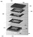
Figure 2 illustrates an example of a stack according to some embodiments of the present invention.
Figure 3 illustrates an enlarged view of a portion of the gasket in the stack illustrated in Figure 2;
Figure 4 illustrates one embodiment of an end plate in accordance with some embodiments of the present invention.
Figure 5 illustrates a cross-section of an end plate in accordance with some embodiments of the present invention.
Figure 6 further illustrates an end plate in accordance with some embodiments of the present invention.
Figures 7A and 7B further illustrate an end plate according to some embodiments of the present invention.
8A and 8B further illustrate an end plate according to some embodiments of the present invention.
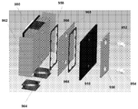
9A and 9B illustrate some embodiments of an electrolytic heat exchanger as illustrated in FIG. 1A.
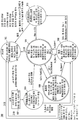
FIG. 10 illustrates a state machine that may be used to control the flow cell system shown in FIG. 1A.
The drawings may be better understood by reading the following detailed description. The drawings are not exhaustive.
바나듐계 화학물질을 이용하는 바나듐 플로우 셀 시스템이 개시된다. 그룹들은 H2SO4 에서 바나듐/바나듐 전해질들을 조사하고 있다. 그 노력으로, V2O5 + V2O3 + H2SO4 은 VOSO4 를 생산한다. V2O5 + H2SO4 의 전기화학적 환원은 또한, VOSO4 를 생산할 수 있다. 그러나, 전해질의 준비는 어렵고 비현실적인 것이 입증되고 있다. 다른 그룹은 HCl 에 VOSO4 를 용해함으로써 H2SO4 및 HCl 의 혼합물을 시도하고 있다. 그러나, 이 전해질은 황산염이 없는 제제 (sulfate free formulation) 를 준비하는데 고가이고 비현실적인 것으로 다시 입증되었다.A vanadium flow cell system using vanadium-based chemicals is disclosed. The groups are investigating vanadium / vanadium electrolytes in H 2 SO 4 . In that effort, V 2 O 5 + V 2 O 3 + H 2 SO 4 produces VOSO 4 . Electrochemical reduction of V 2 O 5 + H 2 SO 4 can also produce VOSO 4 . However, the preparation of electrolytes has proven difficult and unrealistic. Another group is attempting a mixture of H 2 SO 4 and HCl by dissolving VOSO 4 in HCl. However, this electrolyte has proven to be expensive and unrealistic in preparing sulfate free formulations.
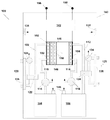
도 1a 는 본 발명의 일부 실시형태들에 따른 플로우 셀 시스템 (100) 을 개념적으로 예시한다. 도 1a 에 도시된 바와 같이, 플로우 셀 시스템 (100) 은 스택 (102) 을 포함한다. 스택 (102) 는 개별적인 플로우 셀들 (146) 의 적층된 배열체이고, 각각의 플로우 셀 (146) 은 멤브레인 (148) 에 의해 분리된 2 개의 하프-셀들을 포함한다. 멤브레인 (148) 은, 예를 들어 미국 특허 제 7,927,731 호에 설명된 바와 같은 이온 투과성 멤브레인일 수 있고, 이 특허는 그 전체가 참조로서 본원에 포함된다. 또한, 셀 (146) 의 각각의 하프-셀은 전극 (150) 을 포함한다. 엔드 셀들은 엔드 전극들 (152 및 154) 을 포함한다. 제어기 (142) 는 엔드 전극들 (152 및 154) 에 커플링되어, 스택 (102) 안팎으로 전하를 제어한다. 제어기 (142) 는, 시스템 (100) 이 방전되는 경우 스택 (102) 으로부터 단자들 (156 및 158) 로 전하를 제공하고, 충전되는 경우 단자들 (156 및 158) 로부터 전하를 수신하여 스택 (102) 에 제공한다. 단자들 (156 및 158) 은 이어서, 시스템 (100) 이 방전되는 경우 전류를 부하에 공급하도록 커플링되고, 시스템 (100) 의 충전을 위해 전원 (예를 들어, 풍력 발전기, 태양 전지, 디젤 발전기, 전력망, 또는 다른 전력 소스) 에 커플링된다.Figure 1A conceptually illustrates a
도 1a 에 예시된 바와 같이, 전해질 용액들은 셀들 (146) 의 하프 셀들 각각을 통해 유동된다. 음극액은 하프 셀들 중 하나를 통해 유동되고, 양극액은 하프 셀들 중 다른 것을 통해 유동된다. 다른 화학물질들이 시스템 (100) 에서의 사용을 위해 제안되고 있으나, 일부 실시형태들에서 바나듐계 화학물질이 전하를 홀딩하고 스택 (102) 으로부터 전하를 제공하는데 이용된다. 바나듐 화학물질은 셀 (146) 의 네거티브 하프 셀에서 V3+ + e- → V2+ 및 셀 (146) 의 포지티브 하프 셀에서 VO2+ + H20 → V02 + + 2H+ + e- (V4 + → V5+ + e- ) 의 반응을 수반한다. 바나듐 화학물질을 이용하는 스택 (102) 에서의 각각의 셀의 이론적인 개방 회로 전압은 그러면, 1.25V (하나의 하프 셀로부터 -0.25 V 및 다른 하프 셀 (108) 로부터 1.00 V) 이다. 이온들 H+ 및 Cl- 은 이 반응 동안 멤브레인 (148) 을 횡단할 수도 있다. 시스템 (100) 에 이용될 수 있는 바나듐 전해질은 미국 특허출원 제 13/651,230 호에서 추가로 설명되고, 이 출원은 그 전체가 참조로서 본원에 포함된다.As illustrated in FIG. 1A, electrolyte solutions flow through each of the half cells of the
도 1a 에 예시된 바와 같이, 전해질들은 탱크들 (104 및 106) 에 저장된다. 탱크 (104) 는 파이프들 (108 및 110) 을 통해 스택 (102) 에 유동적으로 커플링된다. 탱크 (104) 에 저장된 전해질은 펌프 (116) 에 의해 스택 (102) 을 통해 펌핑될 수 있다. 유사하게, 탱크 (106) 는 파이프들 (112 및 114) 을 통해 스택 (102) 에 유동적으로 커플링된다. 탱크 (106) 로부터의 전해질은 펌프 (118) 에 의해 스택 (102) 을 통해 펌핑될 수 있다.As illustrated in FIG. 1A, electrolytes are stored in
도 1a 에 도시된 바와 같이, 시스템 (100) 은 캐비넷 (160) 내에 하우징된다. 시스템 (100) 의 동작 동안, 상당한 양의 열이 시스템 (100), 및 특히 스택 (102) 에 의해 생성될 수도 있다. 일부 실시형태들에서, 냉각 팬들 (138) 이 제공될 수도 있다. 일부 실시형태들에 따른 온도 제어 시스템은 미국특허 제 7,919,204 호에서 설명되어 있으며, 이 특허는 그 전체가 참조로서 본원에 포함된다.As shown in FIG. 1A, the
도 1a 에 추가로 도시된 바와 같이, 시스템 (100) 은 전해질 냉각 시스템들 (120 및 128) 을 포함하고, 이 시스템들은 스택 (102) 으로부터 탱크들 (104 및 106) 각각으로 리턴하는 전해질을 냉각시킨다. 도시된 바와 같이, 파이프 (108) 를 통해 유동하는 스택 (102) 으로부터의 전해질은 전해질 열 교환기 (122) 를 통해 유동할 수 있다. 유사하게, 파이프 (112) 를 통해 유동하는 스택 (102) 으로부터의 전해질은 전해질 열 교환기 (130) 를 통해 유동할 수 있다. 교환기들 (122 및 130) 각각은 전해질 교환기들 (122 및 130) 을 통해 유동되고 열 교환기들 (126 및 136) 각각에 의해 자체 냉각되는 냉각 액체를 이용하여 전해질들을 냉각시킬 수 있다. 펌프들 (124 및 134) 각각은, 열 교환기들 (126 및 136) 각각을 통해, 그리고 열 교환기들 (126 및 136) 각각을 통해 냉각 유체를 순환시킬 수 있다.1A,
도 1a 에 추가로 예시된 바와 같이, 제어 시스템 (142) 은 시스템 (100) 의 각종 양태들을 제어한다. 제어 시스템 (142) 은 스택 (102) 및 전해질 펌프들 (116 및 118) 의 동작을 제어하여 시스템 (100) 을 충전 및 방전시킨다. 제어 시스템 (142) 은 또한, 냉각 팬들 (138) 및 냉각 유체 펌프들 (124 및 134) 을 제어하여 시스템 (100) 의 냉각을 제어할 수 있다. 제어 시스템 (142) 은 시스템 (100) 의 동작에 관한 데이터를 제공하는 각종 센서들 (140) 로부터 신호들을 수신할 수 있다. 제어 시스템 (142) 은 예를 들어, 미국 특허출원 제 12/577,147 호에 설명된 바와 같은 유체 레벨 센서; 미국 특허출원 제 12/790,794 호에 설명된 바와 같은 수소 염소 레벨 검출기들; 또는 미국 특허출원 제 12/790,749 호에 설명된 바와 같은 광학 리크 검출기들을 포함할 수 있고, 이 특허들 각각은 본원에서 그 전체가 참조로서 포함된다.As further illustrated in FIG. 1A, the
전술된 바와 같이, HCl 전해질 내의 바나듐이 미국 특허출원 제 13/651,230 호에서 설명된 바와 같이, 시스템 (100) 에서 이용될 수 있다.As described above, vanadium in the HCl electrolyte can be used in the
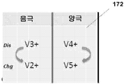
다음의 반응들은 스택 (102) 의 전기화학 셀들 (146) 에서 발생할 수도 있다: 포지티브 하프 셀 (음극액) 에서,The following reactions may occur in the
VOCl2 + H20 + Cl- → VO2Cl + 2HCl + e-;VOCl 2 + H 2 O + Cl - > VO 2 Cl + 2HCl + e - ;
네거티브 하프 셀 (양극액) 에서,In the negative half cell (anolyte solution)
VCl3 + e- → VCl2 + Cl-; 및VCl 3 + e - ? VCl 2 + Cl - ; And
연료 셀 (146) 에서,In the
V0Cl2 + H20 + VCl3 → V02Cl + 2HCl + VCl2. V0Cl 2 + H 2 0 + VCl 3 → V0 2 Cl + 2HCl + VCl 2.
이들 반응들은 도 1b 의 반응도 (172) 에서 도식적으로 예시된다. 도 1a 에 도시된 셀은 전술된 것들과 상이한 반응들 및 상이한 전해질 화학물질을 이용할 수도 있다. 상기 설명은 단지 예시적인 목적을 위한 것이다.These reactions are schematically illustrated in the reaction diagram 172 of FIG. 1B. The cell shown in FIG. 1A may utilize different reactions and different electrolyte chemistries than those described above. The above description is for illustrative purposes only.
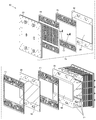
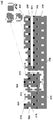
도 2 는 예를 들어, 미국 특허출원 일련번호 12/577,134 및 미국 특허출원 일련번호 13/350,424 호에 설명된 바와 같은 스택 (102) 의 실시형태를 예시하고, 이들 출원 각각은 그 전체가 참조로서 본원에 포함된다. 도 2 에 도시된 바와 같이, 스택 (102) 는 기본적으로 전극 엘리먼트들 (202), 멤브레인 엘리먼트들 (204), 및 가스켓들 (210 및 212) 로 구성된다. 도 2 에 예시된 바와 같이, 전극 엘리먼트들 (202) 은 전극 재료 (208) 가 부착되는 프레임을 포함한다. 멤브레인 엘리먼트들 (204) 은 멤브레인 (206) 이 부착되는 프레임을 포함한다. 가스켓들 (210 및 212) 은 멤브레인들 (206) 과 전극들 (208) 간에 전해질 유체 플로우들을 생성한다. 예시된 바와 같이, 가스켓들 (210 및 212) 은 동일하게 구성되지만 180 도 만큼 회전될 수도 있다. 2 개의 전해질들이 분리되어 엘리먼트들 간의 적합한 플로우 필드들로 지향될 수 있도록 형성된 통로들이 존재한다.2 illustrates an embodiment of
도 2 는 또한, 단자 (152) 를 예시한다. 단자 (152) 는 전극 (208) 을 포함하고, 이 전극은 이 구성에서 전하 컬렉터일 수 있다. 컴포넌트들 (216 및 218) 이 전극 (208) 과 엔드 플레이트 (220) 사이에 샌드위치된다. 컴포넌트들 (216 및 218) 은 절연 시일 (seal) 들일 수도 있다. 엔드 플레이트 (220) 는 알루미늄 엔드 플레이트일 수도 있다. 전극들은 전극 (208) 과 접촉하고 엔드 플레이트 (220) 로부터 확장될 수도 있다. 스택 (102) 는 함께 홀딩되고, 볼트들 (214) 에 의해 팽팽해진다.Fig. 2 also illustrates terminal 152. Fig.
도 3 은 단자 (152) 에서, 집전 장치인, 전극 (208) 과의 인터페이스에서 가스켓 (210) 의 일 실시형태를 예시한다. 확대 (300) 로 예시된 바와 같이, 유체 플로우 인터페이스는 가스켓 (210) 의 플라스틱 슬리브 (306) 를 통해 포트 (302) 와 그래파이트 집전 장치 (208) 사이에서 전해액 유체를 운반하는 채널 (304) 을 포함한다. 시간이 경과함에 따라, 그래파이트 집전 장치 (208) 와 플라스틱 슬리브 (306) 간의 인터페이스로 전해질이 침투하려는 경향이 있고, 이는 결국 전해질로 하여금 집전 장치 단자 (152) 를 통해 누설되게 한다.Figure 3 illustrates one embodiment of a
도 4 는 본 발명의 일부 실시형태들에 따른 단자 (152) 의 집전 장치 (208) 와 가스켓 (210) 간의 인터페이스를 예시한다. 도 4 에 예시된 바와 같이, 터널 (410) 이 제공된다. 입구 (412) 및 출구 (414) 를 포함하는 터널 (410) 은, 그래파이트 집전 장치 (208) 와 슬리브 (306) 간의 인터페이스가 전해질에 노출되지 않고 따라서 전해질 누설의 가능성을 제거하도록 플로우 경로 상에 바이패스를 생성한다. 도 4 에 도시된 바와 같이, 터널 (410) 은 입구 (412) 및 출구 (414) 를 포함하고, 여기서 입구는 가스켓 (210) 에서의 채널 (304) 로부터 유체를 수신하고, 출구는 이 유체를 슬리브 (306) 를 통해 그래파이트 집전 장치 (208) 에 제공한다.Figure 4 illustrates the interface between the
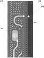
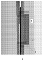
도 5 는 스택 (102) 의 단부의 단면을 예시한다. 도 5 는 멤브레인 엘리먼트 (204), 가스켓 (210), 전극 엘리먼트 (202), 및 엔드 단자 (152) 를 포함한다. 도 5 에 도시된 바와 같이, 위에서 아래로, 제 1 층은 프레임 (204) 과 멤브레인 (206) 을 갖는 멤브레인 층이다. 다음으로 가스켓 (210) 이 있고, 이 가스켓 (210) 은 플로우를 유지하는 펠트 (502) 를 프레이밍한다. 다음의 아래 층은 집전 장치 전극 (208) 을 갖는 다른 프레임 (202) 이고, 이것은 예를 들어 산토프렌 (Santoprene) 으로 형성될 수 있는 프레임에 의해 둘러싸인 티타늄 (504) 으로 형성될 수 있다. 매니폴드로부터의 플로우는 펠트 (502) 로 들어가 터널 (410) 을 통해 절연 엔드플레이트 (218) 를 경유하고, 그래파이트 (208) 바이폴라 플레이트와 프레임 (202) 의 폴리프로필렌 슬리브 간의 인터페이스 에지를 바이패스한다. 절연성 엔드 플레이트 (218) 는, 예를 들어 PVC 플레이트일 수도 있다. 다음 층은 산토프렌으로 형성될 수 있는 엔드 가스켓 (216) 이고, 이 가스켓은 집전 장치를 아래의 층으로부터 분리한다. 다음 층은 절연성 엔드 플레이트 (218) 이다. 알루미늄으로 형성될 수 있는 압력 플레이트 (220) 가, 그 후 스택의 엔드를 완성한다. 도 5 에 도시된 바와 같이, 터널 (410) 은 프레임 (204) 및 가스켓 (210) 을 통과하면서 엔드 플레이트 (218) 에 형성된다. 그래파이트와 플라스틱 프레임 층들 사이의 심 (seam) 상의 수직력 (normal force) 은 그 심을 실링되게 유지한다. 도 5 에 도시된 바와 같이, 플로우 바이-패스 (터널)(410) 는, PVC 로 형성될 수 있는, 엔드 플레이트 (218) 내의 포켓 및 브리지 지지부를 가짐으로써 생성된다. 일부 실시형태들에서, 이 구조는 접착제에 대한 필요성 없이 전해질로부터 집전 장치를 실링한다. 도 6 은 매니폴드 (302) 로부터 터널 (410) 로 그리고 터널 (410) 로부터 입구 (412) 및 출구 (414) 를 경유하는 플로우를 예시한다.5 illustrates a cross section of the end of the
엔드 단자 (156) 에 대한 터널 (410) 의 추가는 추가적인 엔드 플레이트들을 이용하지 않으면서 래버린스 (labyrinth) 채널을 개선시킨다. 부가적으로, 스택 두께의 증가가 필요없다. 비용에서의 미미한 증가는, 현재 PVC 엔드 플레이트들 (216) 상의 블라인드 직사각형 포켓을 기계 가공하고, 플로우를 위한 도관을 제공하기 위해 사출 성형된 CPVC 또는 다른 호환 가능한 플라스틱 삽입부를 사용하는데 있어서, 터널용 그래파이트 (208) 에 생성된 입구 (412) 및 출구 (414) 홀들 주변에 지지부를 추가함으로써 실현된다.The addition of the
도 7a 및 도 7b 는 또한, 엔드 플레이트 (218) 에 형성된 삽입 포켓 (702) 의 구성을 예시한다. 도 7a 에 예시된 바와 같이, 포켓 (702) 은 엔드플레이트 내에 형성되고, 터널 (410) 을 제공하는 삽입부 (704) 는 포켓 (702) 내에 안착되어 형성된다.7A and 7B also illustrate the configuration of the
결과의 터널 (410) 이 도 7b 에 도시된다. 도 7b 에 도시된 바와 같이, 엔드 플레이트 (218) 는 삽입부 (704) 를 포함한다. 도 7b 에 도시된 바와 같이, 가스켓 층 (708) 은 엔드 플레이트 (218) 와 티타늄 층 (504) 을 갖는 집전 층 (216) 사이에 삽입될 수 있다. 각종 지지부들 (706) 이 그래파이트 층 (208) 을 통해 출구 (414) 에 제공되어, 지지를 제공할 수 있다.The resulting
도 8a 및 도 8b 는 또한, 엔드 플레이트의 포켓에 제공된 삽입부를 예시한다. 압축력은 산토프렌이 존재하는 삽입부의 상단을 거친다. 이 힘은 그래파이트 플레이트 (208) 와 PP 슬리브 사이의 갭을 실링한다.Figures 8A and 8B also illustrate an insert provided in the pocket of the end plate. The compressive force passes over the top of the insert where the Santoprene is present. This force seals the gap between the
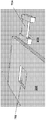
도 1a 에 추가로 예시된 바와 같이, 일부 실시형태들에서 열 교환기들 (122 및 130) 이 제공되어 전해질을, 그들이 탱크들 (104 및 106) 각각으로 리턴할 때 냉각시킨다. 도 9a 는 본 발명의 일부 실시형태들에 따른 열 교환기들 중 하나 (122 또는 130) 일 수 있는, 전해질 열 교환기의 일 실시형태를 예시한다. 전술된 바와 같이, 플로우 배터리들은 열 뿐만 아니라 전기를 생성한다. 이 열은 플로우 셀의 동작을 최적화하기 위해 관리될 것이다. 전해질의 공격적인 성질로 인해, 금속으로 이루어진 종래의 열 교환기들이 전해질을 냉각시키는데 사용될 수 없었다. 따라서, 열 교환기 (900) 는 주로 플라스틱들로 형성된다.As further illustrated in FIG. 1A, in some
일부 플라스틱 열 교환기들이 식별되었으나, 그 비용은 고가이고 유닛들은 큰 것으로 발견되었다. 조사되었던 열 교환기는 모두 튜브-인-쉘 (tube-in-shell) 열 교환기들로 지칭된 유형이었다. 그러나, 유사한 재료들은, 이들 재료들이 전해질에 의해 나타나는 화학적 컨디션들을 견디기 때문에 스택 (102) 의 나머지에서 이용되는 바와 같이, 열 교환기 (900) 에서 이용될 수 있다.Some plastic heat exchangers were identified, but the cost was high and the units were found to be large. All investigated heat exchangers were of the type referred to as tube-in-shell heat exchangers. However, similar materials can be used in the
도 9a 는 본 발명의 일부 실시형태들에 따른 플레이트 유형 열 교환기 (900) 를 예시한다. 열 교환기 (900) 는 플로우 배터리 재료들이고, 그 설계에서 교유하다. 열 교환기 (900) 는 전해질에서의 프로세스 열을, 예를 들어 글리콜과 같은 종래의 냉각 액체로 트랜스퍼하는 액체-투-액체 플레이트 유형 열 교환기이다. 이 설계의 토폴로지는 또한, 플로우 배터리들에 적용될 수 있다; 멤브레인들 및 바이폴라 플레이트들로 플로우 분리기들을 대체하는 것과 같은 변형들이 요구된다.9A illustrates a plate
도 9a 에 도시된 바와 같이, 열 교환기 (900) 는 열 교환 섹션을 구성하는 특정 형상 및 사이즈의 교번 시트들로 형성된다. 패키지는 이 패키지를 압축하는 한 쌍의 압력 플레이트들의 측면에 있다. 이들은 타이 로드들 및 스프링들을 수용하기 위한 홀들을 갖는다. 특히, 도 9a 에 도시된 바와 같이, 열 교환기 (900) 는 압력 플레이트들 (902 와 922) 사이에 형성된다. 압력 플레이트들 (902 및 922) 은 열 교환기 (900) 를 홀딩 및 실링하는 스프링들 및 타이 로드들을 수용하는 정렬된 홀들 (920) 을 포함한다. 도 9a 에 도시된 바와 같이, 가스켓 (904) 은 압력 플레이트 (902) 에 대해 안착되고, 또한 홀들 (920) 을 포함할 수 있다. 가스켓 (924) 은 압력 플레이트 (922) 에 대해 안착되고, 홀들 (920) 을 포함할 수 있다. 가스켓 (924 와 920) 사이에는, 플로우 필드 매체 (906) 와 열 전달 시트들 (908) 이 위치된다. 플로우 필드 매체 (906) 는 각 층에서 90 도 만큼 회전되고, 각각의 플로우 필드 매체 (906) 는 열 전달 시트 (908) 에 의해 다음의 플로우 필드 매체 (906) 로부터 분리된다. 열 전달 시트들 (908) 및 플로우 필드 매체 (906) 각각은 열 교환기 (900) 전체를 모든 유체들이 이동하기 위한 매니폴드들 (910) 을 포함한다. 압력 시트 (902) 및 가스켓 (904) 은 매니폴드들을 포함하지 않고, 이 매니폴드들을 실링한다. 압력 시트 (922) 및 가스켓 (924) 은 2 개의 매체 (하나는 냉각 매체이고 다른 하나는 냉각될 전해질) 의 유입 및 유출을 허용하기 위한 입력 포트들 (912, 913, 916, 및 918) 을 포함한다.As shown in FIG. 9A, the
플로우 매체가 유입구 포트 1 (912) 로 들어갈 때, 그것은 매니폴드 채널들 (910) 중 하나를 경유한 후, 포트 (912) 로부터 플로우 매체를 수신하고 분배하도록 배향되는 이들 플로우 필드 매체 (906) 에서의 플로우 필드 내의 매니폴딩 섹션으로 유동한다. 플로우 매체는 열 전달 시트들 (908) 과 접촉하는 플로우 매체 (906) 를 통해 유동한다. 열 전달 시트들 (908) 의 반대 측 상에서, 다른 플로우 매체는 열 전달 시트들 (908) 과 접촉하여 유동된다. 플로우 필드는 제 1 의 언급된 유동 필드와 동일한 형상 및 사이즈이지만, 도시된 바와 같은 배향을 획득하도록 회전된다. 포트 2 (916) 를 통해 들어가는 다른 매체는 유사한 경로를 따른다. 유체들은 항상 분리되고, 열은 유체 매체 중 하나로부터 열 전달 시트들을 통해 다른 것으로 전달된다. 도 9a 에 도시된 바와 같이, 플로우 매체 1 은 유입구 포트 (912) 통해 들어가고 유출구 포트 (914) 를 통해 나가고, 매체 2 는 유입구 포트 (916) 를 통해 들어가고 유출구 포트 (918) 를 통해 나간다.When the flow medium enters the
열 전달 시트들 (908) 은 폴리에틸렌, 폴리프로필렌, pvdf, 테프론, 경질 고무와 같은 플라스틱들로 만들어질 수 있다. 플로우 유체들 (906) 은 소프트 산토프렌과 같은 더 부드러운 재료로 만들어질 수 있다. 대안의 경질 및 연질 재료들이 반대의 액체들과 환경들 사이의 실링을 확보한다.
도 9a 에 예시된 바와 같은 열 교환기 (900) 의 실시형태는, 2 차원이고 이런 이유로 낮은 비용에서 제조될 수 있는 단지 2 개의 상이한 컴포넌트들을 이용한다. 대안의 시트들의 수는 상이한 열 전달 요건들을 따르도록 쉽게 변경될 수 있다. 어셈블리는 쉽고, 특별한 기법들이 요구되지 않는다. 금속 플레이트 열 교환기들을 이용하는 통상과 같이, 열 교환기 (900) 는 유사하게 레이팅된 튜브-인 쉘-열 교환기에 비해 콤팩트하다.An embodiment of the
플로우 필드 (906) 가 이전의 실시형태에서 연성 고무로 만들어진 열 교환기 (900) 의 다른 실시형태는 단단한 플라스틱 재료로 대체된다. 고무는, 이것이 경질 플라스틱으로 대체되면 손실되는 실링 기능을 수행한다. 실링 기능은 층들을 함께 접착시키거나 용접함으로써 대체될 수 있다. 고무의 제거는 비용을 감소시킬 수 있고, 고무의 존재로 인한 오염이 제거된다.Another embodiment of the
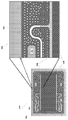
열 교환기 (900) 의 다른 실시형태에서, 전해질은 열을 공기와 교환하고, 따라서 중간의 액체 루프를 이용하지 않는다. 도 9b 는 그러한 전해질 열 교환기 (900) 의 확대도를 예시한다. In another embodiment of the
도 9b 에 도시된 바와 같이, 전해질은 그래파이트 시트들 (960) 사이에서, 공통의 매니폴드 채널들 (966 및 968) 에서 출발하여 이들 안에 수집되어 유동한다. 그래파이트 시트들 (960) 은 특히, 그 구조로 인해 평면의 방향에서 매우 좋은 열 전도체들이다. 전해질은 그래파이트 (960) 및 고무 시트들 (958) 을 적층함으로써 발생하는 구조를 통해 플로우를 포함하고 지향시킬 목적으로 특정 사이즈 및 형상의 고무 시트들 (958) 에 의해 포함된다. 그래파이트 시트들 (960) 은 고무 시트들 (958) 로부터 확장되고 따라서 전해질이 아니고 단지 열이 외부 환경으로 트랜스퍼되도록 한다. 열 교환기 (900) 는 엔드 플레이트 (958) 및 압력 플레이트 (956) 로 형성된다. 사이드 플레이트들 (962) 은 공기의 플로우를 지향시키도록 이용될 수도 있다.As shown in FIG. 9B, the electrolyte begins at the
도 9b 에 추가로 도시된 바와 같이, 전해질은 포트들 (952 및 954) 을 통해 열 교환기 (900) 안 및 밖으로 유동된다. 강제 대류 팬들 (964) 로부터의 공기 플로우는 열의 제거를 제공한다. 그러나 소정 실시형태들에서, 열은 그래파이트 시트들 (960) 을 수직으로 배향시킴으로써 수동적으로 제거될 수 있고, 공기가 들어오는 (air let) 밀도 차이들이 이 프로세스를 가동한다. 이 접근에서, 팬 (964) 은 생략될 수도 있다.As further shown in FIG. 9B, the electrolyte flows into and out of
전해질 플로우는 매우 공격적인 전해질과 화학적으로 호환 가능한 외부 펌프에 의해 가동된다. 포지티브 배치 펌프들 뿐만 아니라 원심 펌프들은 이 호환가능성을 갖고 존재한다. 일반적으로, 원심 펌프들은 그들의 더 긴 수명 때문에 바람직하다. 단점은, 이들 펌프들이 준비될 필요가 있다는 것이다. 이 경우에서 준비 (priming) 는, 펌프가 그늘의 기능을 수행할 수 있기 전에 액체로 채워질 필요가 있다는 것이다. 자동화된 및 수동적인 준비 방법들은 잘 알려져 있고, 유입구 및 유출구 양자에서의 전해질이 항상 액체 레벨 미만에 있는 것을 보장함으로써 준비 방법들은 단지 커미셔닝 동안 및 서비스 동안에만 필요할 것이다. The electrolyte flow is driven by an external pump that is chemically compatible with the highly aggressive electrolyte. Centrifugal pumps as well as positive batch pumps exist with this compatibility. In general, centrifugal pumps are preferred due to their longer life. The disadvantage is that these pumps need to be prepared. In this case, priming means that the pump needs to be filled with liquid before it can perform the function of the shade. Automated and passive preparation methods are well known, and by ensuring that the electrolyte in both the inlet and outlet is always below the liquid level, the preparation methods will only be needed during commissioning and during service.
도 10 은 도 1 에 도시된 바와 같은 제어기 (142) 상에서 실행될 수 있는 본 발명의 일부 실시형태들에 따른 상태 기능 (1000) 을 예시한다. 플로우 셀들에 대한 제어 시스템은 미국 특허출원 일련번호 12/790,793 에서 이전에 설명되었고, 이것은 그 전체가 참조로서 본원에 포함된다.10 illustrates a
도 10 에 도시된 바와 같이, 제어기 (142) 는 시스템 초기화 (1002) 를 파워 온하여 시작한다. 시스템 초기화 상태 (1002) 에서, 제어기 (142) 외부의 모든 내부 레지스터들, 메모리들 및 디바이스들은 스타트 업을 위해 초기화된다. 추가로, 모든 하드웨어 컴포넌트들은 디폴트 상태들로 설정된다. 시스템 초기화 상태 (1002) 로부터, 상태 기능 (1000) 은 ESP동글초기화 (ESPDongleInit) 상태 (1004) 로 트랜지션한다.As shown in FIG. 10, the
ESP동글초기화 상태 (1004) 에서, 제어기 (142) 는 동글 (dongle) 의 존재에 대해 체크하고, 존재하지 않는다면 상태 기능 (1000) 은 경보를 제공하고 충전 상태 (1014) 또는 방전 상태 (1008) 중 어느 하나를 나간다. 동글이 존재하면, 레독스 플로우 배터리 시스템 (Redox Flow Battery System) 파라미터들이 동글로부터 판독된다. Comm bit 가 설정되면, 그것은 외부 커미셔닝 (Commissioning) 프로그램과 통신한다. 그것이 시스템 컴포넌트들을 업데이트하고, Ebox 이 테스트되었는지를 확인하고, Ebox 에서의 임의의 보드들이 변경되었는지 여부를 체크하고, 동글이 등록되지 않은 경우 등록을 위해 동글로부터 서버 정보를 전송하며, DMS 보드로부터 시간 응답 (time ack) 을 대기한다. 대기 시간들은 1 분 내이다. ESP동글초기화 상태 (1004) 로부터, 상태 기능 (1000) 은 En_Buck 신호 및 DongleExBit 에 따라, 충전 상태 (1014) 또는 방전 상태 (1008) 중 어느 하나로 트랜지션한다. DongleExBit 는, 타임아웃이 발생하는 경우 또는 커미셔닝 프로세스가 행해지는 경우 설정된다.In the ESP
충전 상태 (1014) 에서는, 스택 (102) 가 충전된다. 일반적으로, 전력은 BBus 로부터 취해지고, 일정한 전류 충전을 통해 스택 (102) 로 전달된다. 특히, 충전 전류는 동글초기화 상태 (1004) 에서 동글을 판독함으로써 획득되었던 시스템 유형 정보에 의해 결정된다. 다음의 기능들이 그 후 수행된다: 펌프들, 팬들 및 블로어들이 모두 턴 온된다; 충전 전류는 벅 부스트 보드들과의 상호작용에 의해 램프된다; 레벨 제어 알고리즘이 초기화되고 기능적이다; 시스템의 SoC 는, 일단 정상 충전 전류가 확립되면 계산된다 (스택 전압은 SoC 를 계산하기 위해 사용될 수 있음); 시스템의 ESR 은 일단 시스템의 SoC 가 SoC 임계 (SoCthreshold) 를 횡단하면 계산된다; 전해질의 온도가 기록된다; 냉각 시스템 (열 교환기) 알고리즘이 전해질 온도에 기초하여 턴 온된다. 리크 센서들은 임의의 리크들에 대해 연속적으로 모니터링된다. 다음의 컴포넌트들이 모니터링, 기록, 및 보고된다: 모든 팬들 및 블로어 전류들; 제어 보드 상의 모든 전력 공급 전압들; 벅 부스트 보드들 상의 모든 전력 공급 전압들; Ebox, ESP 대기 및 ESP 대기 온도 밖의 온도; Bbus 전압; 및 디젤 생성기 센서 또는 전기 보드 센서와 같은 외부 센서.In the
방전 상태 (1008) 에서는, 전력이 스택 (102) 으로부터 Bbus 로 전달된다. En-Buck 신호는, Bbus 전압이 임계 전압 미만으로 떨어지는 경우 "1" 에서 "0" 으로 변한다. En-Buck 신호 스테이터스에 기초하여, 방전 상태 (1008) 로의 스위칭이 일어난다. 방전 상태 (1008) 는 충전 전류 제어가 발생하지 않는 것을 제외하고 충전 상태 (1014) 의 기능들 모두를 수행한다; ESR 계산은 발생하지 않는다; 디젤 생성기를 제어하기 위한 PFC 가 수행된다; 그리고 ABB 가 턴 온되면, SoC 가 높은 경우 그것은 턴 온된다.In the
플로트 (Float) 상태 (1006) 는, SOC 가 플로트SOC (FloatSoC) 값보다 큰 경우 충전 상태 (1014) 로부터 트랜지션된다. FloatSoC 는 커미셔닝 프로그램에 의해 또는 시스템 동글에서의 FRP 시스템에 의해 셋업된다. 벅 부스트는 온 상태에 있고, BBus 전력이 사라지고 임계 값 미만으로 떨어지는 경우 방전하도록 준비 유지된다. 플로트 상태 (1006) 에서, 충전 전류는 정지된다; 펌프들은 정지된다; 그리고 팬들 및 블로어들은 정지된다. 전해질의 온도가 기록되고, 냉각 시스템 알고리즘이 온되며 냉각 시스템이 전해질 온도에 기초하고, 리크 센서들이 임의의 리크들에 대해 모니터링되며, 충전 상태 (1014) 에서 행해진 것처럼 컴포넌트들이 모니터링, 기록, 및 보고된다. 펌프들이 정지된 이후로, 스택에서의 전해질은 배출되지 않는다. 그러나, 스택 전압은 셀프 방전 프로세스로 인해 천천히 감쇠한다. 스택 전압은 연속적으로 모니터링되고, 스택 전압이 임계 전압 미만으로 떨어지는 경우 펌프들은 약 90 분 동안 턴 온된다. 이 시간 동안, 새로운 (fresh) 전해질이 스택 안으로 제공된다. 전해질의 SoC 는, 펌프들이 가동되는 경우 계산된다. 일단 펌프가 정지하면, 새로운 전해질은 스택에 머물고 따라서 스택 전압이 임계 전압 보다 높아진다. 스택 전압은 이제, 천천히 셀프 방전하고 전압은 임계 전압 미만으로 떨어지며 그 후 펌프가 다시 턴 온된다. 이 프로세스는, 시스템의 SoC 가 임계 SoC 미만으로 떨어질 때까지 반복을 유지한다. 일단 이것이 임계 SoC 미만으로 떨어지면, 시스템은 충전 모드 (1014) 로 리턴한다.
SoC 가 SOC하이버네이트임계 (SoCHibernatethreshold) 미만으로 떨어지는 경우, 방전 상태 (1008) 로부터 하이버네이트 (Hibernate) 상태 (1010) 로 진입된다. 하이버네이트 상태에서, 펌프들은 턴 오프되고, 벅 부스트는 턴 오프되며, 냉각 시스템 알고리즘은 턴 오프된다. 전해질의 온도가 기록되고, 리크 센서들이 임의의 리크들에 대해 모니터링되며, 충전 상태 (1014) 에서 행해진 것 처럼 컴포넌트들이 모니터링, 기록, 및 보고된다. 상태 기능 (1000) 은, BBus 전력이 재개되고 또는 스택 (102) 의 전력 손실로 인한 고장이 발생하는 경우 하이버네이트 상태 (1010) 로부터 변할 것이고, 상태 기능 (1000) 이 셧다운 (1002) 으로 트랜지션한다.When the SoC falls below the SOC Hibernate threshold, it enters the
상태 기능 (1000) 은, 에러가 발생하는 경우 임의의 다른 상태로부터 셧다운 상태로 (1012) 로 트랜지션한다. 이 상태에서, 모든 기능들은 모니터링 기능을 제외하고는 디스에이블된다. 셧다운 상태 (1012) 로부터의 리커버리는, 원격 SMS 커맨드에 의해, BBus 전력이 이용 가능한 경우, 또는 엔트리가 하이버네이트 상태 (1010) 를 통하고 BBus 전압이 52V 보다 큰 경우 BTS 스위치를 턴 온/오프함으로써 발생한다.The
앞선 상세한 설명에서, 각종 실시형태들은 첨부한 도면들을 참조하여 설명되었다. 그러나, 다음의 청구항들에 대한 세트로서 본 발명의 광범위한 범위로부터 벗어남 없이, 각종 변형들 및 변경들이 실시형태들에 대하여 이루어질 수 있고, 추가의 실시형태들이 구현될 수도 있다는 것이 명백할 것이다. 상세한 설명 및 도면들은 따라서, 제한적 의미 보다는 예시적인 것으로 간주된다.
In the foregoing detailed description, various embodiments have been described with reference to the accompanying drawings. It will, however, be evident that various modifications and changes can be made to the embodiments and additional embodiments may be implemented without departing from the broader scope of the invention as a set of the following claims. The description and drawings are, accordingly, to be regarded as illustrative rather than limiting.
Claims (3)
상기 엔드 플레이트 구조는,
집전 플레이트;
상기 집전 플레이트와 접촉하고 유체 매니폴드들을 포함하는, 가스켓 프레임;
상기 가스켓 프레임 내의 펠트 (felt);
엔드 플레이트로서, 상기 집전 플레이트는 상기 엔드 플레이트와 상기 가스켓 프레임 사이에 위치되고, 상기 엔드 플레이트는 삽입부를 수용하기 위한 포켓을 갖는, 상기 엔드 플레이트; 및
상기 가스켓 프레임과 상기 펠트 사이의 전해질 플로우를 위한 터널 구조를 형성하는 상기 엔드 플레이트를 갖는 삽입부를 포함하는, 스택.A stack for a flow cell system having an end plate structure,
In the end plate structure,
Current collection plate;
A gasket frame in contact with said current collector plate and comprising fluid manifolds;
A felt in the gasket frame;
An end plate, wherein the current collecting plate is positioned between the end plate and the gasket frame, and the end plate has a pocket for receiving the insertion portion; And
And an insert having the end plate forming a tunnel structure for electrolyte flow between the gasket frame and the felt.
플로우 필드 (flow field) 매체; 및
상기 플로우 필드 매체를 분리하는 열 전달 시트들을 포함하고,
전해질 및 열 교환 유체는 상기 전해질 열 교환기를 통해 유동될 수 있는, 플로우 셀 시스템.A flow cell system having an electrolytic heat exchanger,
A flow field medium; And
And heat transfer sheets separating the flow field media,
Wherein the electrolyte and the heat exchange fluid can flow through the electrolyte heat exchanger.
상기 제어기는,
초기화 상태;
ESP동글초기화 (ESPDongleInit) 상태;
충전 상태;
방전 상태;
플로트 (float) 상태;
하이버네이트 (hibernate) 상태; 및
셧다운 상태를 갖는 코드를 실행하고,
상기 상태들 간에 트랜지션들이 이루어지는, 플로우 시스템.
A flow system having a controller,
The controller comprising:
Initialization state;
ESP dongle initialization (ESPDongleInit) state;
Charge status;
Discharge state;
Float state;
Hibernate state; And
Executes a code having a shutdown state,
Wherein transitions are made between the states.
Applications Claiming Priority (5)
| Application Number | Priority Date | Filing Date | Title |
|---|---|---|---|
| US201261645495P | 2012-05-10 | 2012-05-10 | |
| US61/645,495 | 2012-05-10 | ||
| US13/842,446 US9276274B2 (en) | 2012-05-10 | 2013-03-15 | Vanadium flow cell |
| US13/842,446 | 2013-03-15 | ||
| PCT/US2013/040214 WO2013169950A1 (en) | 2012-05-10 | 2013-05-08 | Vanadium flow cell |
Related Child Applications (1)
| Application Number | Title | Priority Date | Filing Date |
|---|---|---|---|
| KR1020177003322A Division KR20170017013A (en) | 2012-05-10 | 2013-05-08 | Vanadium flow cell |
Publications (1)
| Publication Number | Publication Date |
|---|---|
| KR20150018547A true KR20150018547A (en) | 2015-02-23 |
Family
ID=49548867
Family Applications (2)
| Application Number | Title | Priority Date | Filing Date |
|---|---|---|---|
| KR1020147034241A KR20150018547A (en) | 2012-05-10 | 2013-05-08 | Vanadium flow cell |
| KR1020177003322A KR20170017013A (en) | 2012-05-10 | 2013-05-08 | Vanadium flow cell |
Family Applications After (1)
| Application Number | Title | Priority Date | Filing Date |
|---|---|---|---|
| KR1020177003322A KR20170017013A (en) | 2012-05-10 | 2013-05-08 | Vanadium flow cell |
Country Status (10)
| Country | Link |
|---|---|
| US (2) | US9276274B2 (en) |
| EP (1) | EP2847815A4 (en) |
| JP (1) | JP2015520484A (en) |
| KR (2) | KR20150018547A (en) |
| CN (1) | CN104508880B (en) |
| AU (1) | AU2013259537B2 (en) |
| BR (1) | BR112014027959A2 (en) |
| HK (1) | HK1208765A1 (en) |
| WO (1) | WO2013169950A1 (en) |
| ZA (1) | ZA201408405B (en) |
Families Citing this family (15)
| Publication number | Priority date | Publication date | Assignee | Title |
|---|---|---|---|---|
| JP6256202B2 (en) * | 2014-05-29 | 2018-01-10 | 住友電気工業株式会社 | Electrolyte circulating battery |
| US9655285B2 (en) | 2014-11-28 | 2017-05-16 | Elwha Llc | Power supply system and method of managing the same |
| WO2017023068A1 (en) * | 2015-07-31 | 2017-02-09 | 오씨아이 주식회사 | Redox flow battery heat exchanger and redox flow battery including same |
| CN109075366A (en) * | 2016-04-21 | 2018-12-21 | 住友电气工业株式会社 | Container type battery |
| FR3059469B1 (en) * | 2016-11-28 | 2019-05-17 | Kemiwatt | REDOX ELECTROCHEMICAL CELL IN REDUCED SHUNT FLUX |
| RU2747794C2 (en) | 2016-12-19 | 2021-05-14 | Ларго Клин Энерджи Корп. | Systems and methods for storing electrolyte and detecting failures in flow batteries |
| US20190296383A1 (en) | 2017-03-13 | 2019-09-26 | Ifbattery Inc. | Electrochemical Cells |
| PE20200028A1 (en) * | 2017-03-27 | 2020-01-09 | Storen Tech Inc | PHYSICAL MATERIALIZATION OF TANKS FOR A FLOW BATTERY |
| US11233257B2 (en) * | 2017-04-28 | 2022-01-25 | Ess Tech, Inc. | Methods and system for a battery |
| KR102401319B1 (en) * | 2017-11-28 | 2022-05-24 | 스미토모덴키고교가부시키가이샤 | redox flow battery |
| CN111653812B (en) * | 2020-06-09 | 2022-06-03 | 国网电力科学研究院有限公司 | Novel vanadium cell stack capable of being modularized |
| WO2022031900A1 (en) * | 2020-08-06 | 2022-02-10 | Ifbattery Inc. | Battery system |
| US20230107172A1 (en) * | 2021-10-01 | 2023-04-06 | Lockheed Martin Energy, Llc | One-piece pressure plate collector |
| WO2023091940A1 (en) * | 2021-11-16 | 2023-05-25 | Quino Energy, Inc. | System and process for rebalancing flow battery state of charge |
| DE102022115645A1 (en) * | 2022-06-23 | 2023-12-28 | Schaeffler Technologies AG & Co. KG | Redox flow battery and method for producing a redox flow battery |
Family Cites Families (31)
| Publication number | Priority date | Publication date | Assignee | Title |
|---|---|---|---|---|
| US3554810A (en) * | 1967-04-12 | 1971-01-12 | Solomon Zaromb | Metal-oxygen power source |
| JPH0821400B2 (en) * | 1987-03-04 | 1996-03-04 | 関西電力株式会社 | Electrolyte circulation type secondary battery |
| JP3505918B2 (en) * | 1996-06-19 | 2004-03-15 | 住友電気工業株式会社 | Redox flow battery |
| JP2000188116A (en) * | 1998-12-22 | 2000-07-04 | Sumitomo Electric Ind Ltd | Cell frame, cell stack and battery using them |
| JP3890799B2 (en) * | 1999-03-24 | 2007-03-07 | いすゞ自動車株式会社 | Plate fin heat exchanger |
| JP2003079070A (en) * | 2000-09-28 | 2003-03-14 | Kansai Electric Power Co Inc:The | Electric power storage system |
| JP4000248B2 (en) * | 2001-06-08 | 2007-10-31 | 本田技研工業株式会社 | FUEL CELL STACK AND METHOD OF PRESSURE AND HOLDING THE SAME |
| US6884537B2 (en) | 2001-12-20 | 2005-04-26 | Freudenberg-Nok General Partnership | Structural seal for a fuel cell |
| JP3711076B2 (en) * | 2002-02-13 | 2005-10-26 | 関西電力株式会社 | Method for creating electrical equivalent circuit model of redox flow battery, simulation method and program using the same |
| JP3873849B2 (en) * | 2002-08-27 | 2007-01-31 | トヨタ自動車株式会社 | Polymer electrolyte fuel cell device |
| JP2004167334A (en) * | 2002-11-19 | 2004-06-17 | Showa Aircraft Ind Co Ltd | Apparatus for recovering solvent of high boiling point |
| JP2004278986A (en) * | 2003-03-18 | 2004-10-07 | Matsushita Electric Ind Co Ltd | Laminated heat exchanger |
| JP3877714B2 (en) * | 2003-08-21 | 2007-02-07 | 株式会社竹中工務店 | Power storage system |
| JP2005142056A (en) * | 2003-11-07 | 2005-06-02 | Kansai Electric Power Co Inc:The | Redox flow battery system |
| US8277964B2 (en) * | 2004-01-15 | 2012-10-02 | Jd Holding Inc. | System and method for optimizing efficiency and power output from a vanadium redox battery energy storage system |
| FI120476B (en) | 2004-10-28 | 2009-10-30 | Waertsilae Finland Oy | Flow arrangement of fuel cell stacks |
| JP2006313691A (en) * | 2005-05-09 | 2006-11-16 | Sumitomo Electric Ind Ltd | Redox flow battery system |
| JP4243322B2 (en) | 2006-07-28 | 2009-03-25 | パナソニック株式会社 | Fuel cell and fuel cell system |
| US7927731B2 (en) | 2008-07-01 | 2011-04-19 | Deeya Energy, Inc. | Redox flow cell |
| US8785023B2 (en) * | 2008-07-07 | 2014-07-22 | Enervault Corparation | Cascade redox flow battery systems |
| US20100136455A1 (en) | 2008-10-10 | 2010-06-03 | Rick Winter | Common Module Stack Component Design |
| US7919204B2 (en) | 2008-10-10 | 2011-04-05 | Deeya Energy, Inc. | Thermal control of a flow cell battery |
| US20100291429A1 (en) * | 2009-05-12 | 2010-11-18 | Farmer Joseph C | Electrochemical Nanofluid or Particle Suspension Energy Conversion and Storage Device |
| US8587255B2 (en) | 2009-05-28 | 2013-11-19 | Deeya Energy, Inc. | Control system for a flow cell battery |
| JP5558879B2 (en) * | 2010-03-25 | 2014-07-23 | 大阪瓦斯株式会社 | Solid oxide fuel cell system |
| US9281535B2 (en) | 2010-08-12 | 2016-03-08 | Imergy Power Systems, Inc. | System dongle |
| WO2012032368A1 (en) | 2010-09-07 | 2012-03-15 | Krisada Kampanatsanyakorn | Multi-tier redox flow cell stack of monopolar cells with juxtaposed sideway extended bipolar intercell interconnects on every tier of the stack |
| US9083019B2 (en) * | 2011-06-14 | 2015-07-14 | United Technologies Corporation | System and method for operating a flow battery system at an elevated temperature |
| CN102306815A (en) * | 2011-08-24 | 2012-01-04 | 中国东方电气集团有限公司 | Liquid flow cell system |
| CN102354764B (en) * | 2011-08-24 | 2013-11-20 | 中国东方电气集团有限公司 | Energy supply system and control method thereof |
| US9774044B2 (en) * | 2011-09-21 | 2017-09-26 | United Technologies Corporation | Flow battery stack with an integrated heat exchanger |
-
2013
- 2013-03-15 US US13/842,446 patent/US9276274B2/en not_active Expired - Fee Related
- 2013-05-08 CN CN201380024443.8A patent/CN104508880B/en not_active Expired - Fee Related
- 2013-05-08 JP JP2015511673A patent/JP2015520484A/en active Pending
- 2013-05-08 KR KR1020147034241A patent/KR20150018547A/en active Application Filing
- 2013-05-08 WO PCT/US2013/040214 patent/WO2013169950A1/en active Application Filing
- 2013-05-08 BR BR112014027959A patent/BR112014027959A2/en not_active IP Right Cessation
- 2013-05-08 AU AU2013259537A patent/AU2013259537B2/en not_active Ceased
- 2013-05-08 KR KR1020177003322A patent/KR20170017013A/en not_active Application Discontinuation
- 2013-05-08 EP EP13787368.3A patent/EP2847815A4/en not_active Withdrawn
-
2014
- 2014-11-17 ZA ZA2014/08405A patent/ZA201408405B/en unknown
-
2015
- 2015-09-22 HK HK15109293.8A patent/HK1208765A1/en unknown
-
2016
- 2016-03-01 US US15/058,140 patent/US20160204458A1/en not_active Abandoned
Also Published As
| Publication number | Publication date |
|---|---|
| BR112014027959A2 (en) | 2017-06-27 |
| US20130302710A1 (en) | 2013-11-14 |
| US9276274B2 (en) | 2016-03-01 |
| CN104508880A (en) | 2015-04-08 |
| AU2013259537A1 (en) | 2014-12-11 |
| EP2847815A4 (en) | 2016-01-13 |
| JP2015520484A (en) | 2015-07-16 |
| HK1208765A1 (en) | 2016-03-11 |
| EP2847815A1 (en) | 2015-03-18 |
| WO2013169950A1 (en) | 2013-11-14 |
| KR20170017013A (en) | 2017-02-14 |
| AU2013259537B2 (en) | 2016-06-02 |
| US20160204458A1 (en) | 2016-07-14 |
| CN104508880B (en) | 2017-06-09 |
| ZA201408405B (en) | 2016-02-24 |
Similar Documents
| Publication | Publication Date | Title |
|---|---|---|
| US9276274B2 (en) | Vanadium flow cell | |
| Reed et al. | Performance of Nafion® N115, Nafion® NR-212, and Nafion® NR-211 in a 1 kW class all vanadium mixed acid redox flow battery | |
| EP1051766B1 (en) | Redox flow battery system and cell stack | |
| Tokuda et al. | Development of a redox flow battery system | |
| US20100136455A1 (en) | Common Module Stack Component Design | |
| JP2015522913A (en) | Electrochemical equilibrium in vanadium flow batteries. | |
| KR101335544B1 (en) | Redox flow battery | |
| US9362582B2 (en) | Flow cell stack with single plate cells | |
| US20130154364A1 (en) | Vanadium redox battery energy storage system | |
| KR101176575B1 (en) | Device for flowing electrolyte in redox flow battery | |
| US20200075969A1 (en) | Redox-flow electrochemical cell with decreased shunt | |
| WO2013149512A1 (en) | Current collector, double-electrode current collector comprising same, single battery, and flow battery | |
| US7314676B2 (en) | Fuel-cell stack | |
| US20190109334A1 (en) | Cell plates for redox flow batteries | |
| JP2006040591A (en) | Redox flow battery | |
| JP2004234973A (en) | Fuel cell unit and operation method of the same | |
| TWI661605B (en) | Flow battery stack | |
| CN202308171U (en) | Flat plate configuration type redox flow cell | |
| EP1646099A2 (en) | Electrochemical device | |
| CN112993360B (en) | Zinc-bromine single-flow galvanic pile and battery | |
| KR102126343B1 (en) | Redox flow battery | |
| US11309550B2 (en) | Leaks containment embodiment for electrochemical stack | |
| KR101958166B1 (en) | A oxidation-reduction flow battery system | |
| KR101423068B1 (en) | Redox flow battery using ion-exchang tube | |
| WO2009116102A1 (en) | Electro-chemical device |
Legal Events
| Date | Code | Title | Description |
|---|---|---|---|
| A201 | Request for examination | ||
| A302 | Request for accelerated examination | ||
| AMND | Amendment | ||
| E902 | Notification of reason for refusal | ||
| AMND | Amendment | ||
| E601 | Decision to refuse application | ||
| AMND | Amendment | ||
| A107 | Divisional application of patent | ||
| J201 | Request for trial against refusal decision | ||
| J301 | Trial decision |
Free format text: TRIAL NUMBER: 2017101000625; TRIAL DECISION FOR APPEAL AGAINST DECISION TO DECLINE REFUSAL REQUESTED 20170206 Effective date: 20170530 |