KR20150010733A - Energy transfer device - Google Patents
Energy transfer device Download PDFInfo
- Publication number
- KR20150010733A KR20150010733A KR1020147031820A KR20147031820A KR20150010733A KR 20150010733 A KR20150010733 A KR 20150010733A KR 1020147031820 A KR1020147031820 A KR 1020147031820A KR 20147031820 A KR20147031820 A KR 20147031820A KR 20150010733 A KR20150010733 A KR 20150010733A
- Authority
- KR
- South Korea
- Prior art keywords
- pyrotechnic
- section
- insert
- housing
- energy
- Prior art date
Links
Images

Classifications
-
- C—CHEMISTRY; METALLURGY
- C06—EXPLOSIVES; MATCHES
- C06C—DETONATING OR PRIMING DEVICES; FUSES; CHEMICAL LIGHTERS; PYROPHORIC COMPOSITIONS
- C06C5/00—Fuses, e.g. fuse cords
- C06C5/06—Fuse igniting means; Fuse connectors
-
- F—MECHANICAL ENGINEERING; LIGHTING; HEATING; WEAPONS; BLASTING
- F42—AMMUNITION; BLASTING
- F42C—AMMUNITION FUZES; ARMING OR SAFETY MEANS THEREFOR
- F42C15/00—Arming-means in fuzes; Safety means for preventing premature detonation of fuzes or charges
- F42C15/28—Arming-means in fuzes; Safety means for preventing premature detonation of fuzes or charges operated by flow of fluent material, e.g. shot, fluids
- F42C15/31—Arming-means in fuzes; Safety means for preventing premature detonation of fuzes or charges operated by flow of fluent material, e.g. shot, fluids generated by the combustion of a pyrotechnic or explosive charge within the fuze
-
- F—MECHANICAL ENGINEERING; LIGHTING; HEATING; WEAPONS; BLASTING
- F42—AMMUNITION; BLASTING
- F42C—AMMUNITION FUZES; ARMING OR SAFETY MEANS THEREFOR
- F42C19/00—Details of fuzes
- F42C19/08—Primers; Detonators
- F42C19/0815—Intermediate ignition capsules, i.e. self-contained primary pyrotechnic module transmitting the initial firing signal to the secondary explosive, e.g. using electric, radio frequency, optical or percussion signals to the secondary explosive
-
- E—FIXED CONSTRUCTIONS
- E21—EARTH DRILLING; MINING
- E21B—EARTH DRILLING, e.g. DEEP DRILLING; OBTAINING OIL, GAS, WATER, SOLUBLE OR MELTABLE MATERIALS OR A SLURRY OF MINERALS FROM WELLS
- E21B43/00—Methods or apparatus for obtaining oil, gas, water, soluble or meltable materials or a slurry of minerals from wells
- E21B43/11—Perforators; Permeators
-
- E—FIXED CONSTRUCTIONS
- E21—EARTH DRILLING; MINING
- E21B—EARTH DRILLING, e.g. DEEP DRILLING; OBTAINING OIL, GAS, WATER, SOLUBLE OR MELTABLE MATERIALS OR A SLURRY OF MINERALS FROM WELLS
- E21B7/00—Special methods or apparatus for drilling
- E21B7/007—Drilling by use of explosives
-
- F—MECHANICAL ENGINEERING; LIGHTING; HEATING; WEAPONS; BLASTING
- F42—AMMUNITION; BLASTING
- F42C—AMMUNITION FUZES; ARMING OR SAFETY MEANS THEREFOR
- F42C19/00—Details of fuzes
- F42C19/08—Primers; Detonators
- F42C19/0807—Primers; Detonators characterised by the particular configuration of the transmission channels from the priming energy source to the charge to be ignited, e.g. multiple channels, nozzles, diaphragms or filters
-
- F—MECHANICAL ENGINEERING; LIGHTING; HEATING; WEAPONS; BLASTING
- F42—AMMUNITION; BLASTING
- F42D—BLASTING
- F42D1/00—Blasting methods or apparatus, e.g. loading or tamping
- F42D1/04—Arrangements for ignition
- F42D1/043—Connectors for detonating cords and ignition tubes, e.g. Nonel tubes
-
- F—MECHANICAL ENGINEERING; LIGHTING; HEATING; WEAPONS; BLASTING
- F42—AMMUNITION; BLASTING
- F42C—AMMUNITION FUZES; ARMING OR SAFETY MEANS THEREFOR
- F42C9/00—Time fuzes; Combined time and percussion or pressure-actuated fuzes; Fuzes for timed self-destruction of ammunition
- F42C9/10—Time fuzes; Combined time and percussion or pressure-actuated fuzes; Fuzes for timed self-destruction of ammunition the timing being caused by combustion
Landscapes
- Engineering & Computer Science (AREA)
- General Engineering & Computer Science (AREA)
- Life Sciences & Earth Sciences (AREA)
- Mining & Mineral Resources (AREA)
- Geology (AREA)
- Environmental & Geological Engineering (AREA)
- Physics & Mathematics (AREA)
- Fluid Mechanics (AREA)
- General Life Sciences & Earth Sciences (AREA)
- Geochemistry & Mineralogy (AREA)
- Organic Chemistry (AREA)
- Chemical & Material Sciences (AREA)
- Air Bags (AREA)
- Wind Motors (AREA)
- Automotive Seat Belt Assembly (AREA)
Abstract
본 발명은 발사를 개시하기 위하여 파이로테크닉 장치(52)로부터의 에너지 출력을 또 다른 장치(78)에 전달할 수 있는 에너지 전달 장치(10)에 관한 것이다. 상기 장치(10)는 변형될 수 있는 장치 인서트(14)가 내부에 수용되는 장치 하우징(12)을 포함한다. 장치 인서트(14)는 출력, 가령, 에너지, 가스 및/또는 고체를 파이로테크닉 장치(52)로부터 또 다른 파이로테크닉 장치(78)에 전달하기 위해 중앙 통로(34)를 포함한다. 통로(34)는 파이로테크닉 장치 출력을 제2 파이로테크닉 장치(78) 상의 정확한 위치에 전달하는데, 상기 정확한 위치에서 발사 공정이 가장 효율적으로 개시된다. 에너지 전달 장치(10)는 웰 완결 공정에 사용되는 공구(44)의 일부분으로서 사용될 수도 있다. The present invention is directed to an energy delivery device (10) that is capable of delivering energy output from a pyrotechnic device (52) to another device (78) to initiate a fire. The device 10 includes a device housing 12 in which a device insert 14, which can be deformed, is received therein. The device insert 14 includes a central passage 34 for delivering power, e.g., energy, gas, and / or solids, from the pyrotechnic device 52 to another pyrotechnic device 78. The passageway 34 delivers the pyrotechnic device output to the correct location on the second pyrotechnic device 78, where the firing process is most efficiently initiated at that precise location. The energy transfer device 10 may be used as part of the tool 44 used in the well completion process.
Description
본 특허출원은 2012년 4월 24일에 출원된 미국 가특허출원번호 61/637,541호를 기초로 우선권을 주장하고 있는데, 상기 미국 특허출원은 전반적으로 본 명세서에서 참조문헌으로 인용된다. This patent application claims priority from U.S. Provisional Patent Application No. 61 / 637,541, filed April 24, 2012, which is incorporated herein by reference in its entirety.
본 발명은 제2 파이로테크닉 장치의 발사를 개시하기 위하여 제1 파이로테크닉 장치의 출력으로부터 릴리스된 에너지를 제2 파이로테크닉 장치에 전달하도록 구성된 에너지 전달 장치에 관한 것이다. 상기 에너지 전달 장치는 제1 파이로테크닉 장치의 출력 차지(output charge), 가령, 시간 지연 퓨즈에 의해 릴리스된 에너지를 흡수하고 이 에너지의 일부분 이상을 제2 파이로테크닉 장치를 향해 안내하여, 조절 방식으로 제2 파이로테크닉 장치를 효율적이면서도 안정적으로 발사할 수 있게 한다.
The invention relates to an energy transfer device configured to transfer energy released from the output of a first pyrotechnic device to a second pyrotechnic device to initiate firing of the second pyrotechnic device. The energy transfer device absorbs the output charge of the first pyrotechnic device, e.g., the energy released by the time delay fuse, and guides at least a portion of this energy toward the second pyrotechnic device, The second pyrotechnic device can be efficiently and stably fired.
파이로테크닉 장치(pyrotechnic device)는 일반적으로 다양한 산업 용도, 가령, 유정 완결 공정(well completion operation)에서 폭발장약(explosive charge)을 점화하거나 폭발시키도록 사용된다. 시간 지연 퓨즈(time delay fuse)는 폭파 공정(blasting operation)에 사용되는 폭발 물질(explosive material)의 폭발을 점화하도록 사용될 수 있는 대표적인 파이로테크닉 장치이다. 시간 지연 퓨즈는 일반적으로 사전결정된 지연 시간 증분량(delay time increment)에서 사용 가능하다. 하지만, 특정 분야에서, 단일의 시간 지연 퓨즈가 공급되도록 구성되는 것에 비해 더 긴 시간 지연이 바람직하다. 이러한 경우에서, 폭파 공정 운영자(blasting operator)는, 한 퓨즈로부터의 출력 차지(output charge)가 그 다음 퓨즈의 점화 차지(ignition charge) 또는 프라이머(primer)를 점화할 것이라는 것을 제외하고는, 복수의 퓨즈를 일렬로(in series) 적재할 수 있다(stack). Pyrotechnic devices are commonly used to ignite or explode explosive charges in various industrial applications, such as well completion operations. A time delay fuse is a typical pyrotechnic device that can be used to ignite an explosion of explosive material used in a blasting operation. A time delay fuse is generally available in a predetermined delay time increment. However, in certain applications, a longer time delay is desirable compared to being configured to supply a single time delay fuse. In such a case, the blasting operator is able to determine whether the output charge from one fuse will then ignite the ignition charge or primer of the fuse, Fuses can be stacked in series.
시간 지연 퓨즈는 통상 이와 같은 방식으로는 사용하도록 구성되거나 설계되지 않는다. 따라서, 특정 환경에서, 시간 지연 퓨즈로부터의 출력 차지(output charge)는 근접한 퓨즈를 점화시키는 데 실패할 수 있어서 이에 따라 폭파 공정에 사용되는 기폭약(primary explosive)을 폭발시키는 데 실패하게 된다. 다운홀 공정(downhole operation)의 관점에서 볼 때, 기폭약을 폭발시키는 데 실패함으로써, 기폭약을 포함하는 공구(tool)가 홀을 백업(back up)하도록 제공되고 시간 지연 퓨즈의 새로운 스트링(new string)이 설치될 필요가 생겼을 수 있다. 파이프 스트링(pipe string)을 끌어당기는(pulling) 공정은 값비싸고 시간이 많이 소요되는 공정이다. 본질적으로 위험한 특성으로 인해, 폭발 장치(explosive device)가 제공됨으로써 상기 공정은 더 복잡하게 된다. A time delay fuse is not normally configured or designed for use in this manner. Thus, in certain circumstances, the output charge from the time delay fuse may fail to ignite adjacent fuses, thereby failing to explode the primary explosive used in the blowing process. In view of the downhole operation, a failure in exploding the explosive may cause a tool including an explosive to be provided to back up the hole and to provide a new string of time delay fuses, May need to be installed. Pulling a pipe string is a costly and time consuming process. Due to inherently dangerous properties, the process becomes more complicated by providing an explosive device.
따라서, 종래 기술에서, 하나의 시간 지연 퓨즈로부터의 출력 에너지를 또 다른 시간 지연 퓨즈로 효율적이면서도 안정적으로 전달하여, 그 다음 퓨즈에서 연쇄 점화(chain ignite)를 제공할 필요성이 존재한다.
Thus, in the prior art, there is a need to efficiently and stably transfer the output energy from one time delay fuse to another time delay fuse, which in turn provides chain ignition in the fuse.
본 발명은 제2 파이로테크닉 장치(pyrotechnic device)의 발사(firing)를 개시하기(initiating) 위하여 제1 파이로테크닉 장치로부터의 에너지 출력(energy output)을 제2 파이로테크닉 장치에 전달하도록 구성된 에너지 전달 장치(energy transfer device)를 제공함으로써 상기 언급한 문제점에 대한 해결책을 제공한다. 한 실시예에서, 에너지 전달 장치는 제1 파이로테크닉 장치에 근접하게 배열되도록 구성된 전방 섹션(forward section) 및 제2 파이로테크닉 장치에 근접하게 배열되도록 구성된 후미 섹션(aft section)을 포함하는 금속성 본체(metallic body)를 포함한다. 상기 금속성 본체는 내부를 통해 연장되는 축방향 통로(axial passageway)를 추가로 포함한다. 상기 통로는 본체 전방 섹션을 통해 연장되는 제1 세그먼트(segment)와 본체 후미 섹션을 통해 연장되는 제2 세그먼트를 포함한다. 본체 전방 섹션은 통로 제1 세그먼트의 직경이 좁아져서 통로 내에 수축부(constriction)가 형성되도록 제1 파이로테크닉 장치로부터의 에너지 출력에 의해 변형될 수 있다(deformable). The present invention is configured to transfer an energy output from a first pyrotechnic device to a second pyrotechnic device to initiate a firing of a second pyrotechnic device, The present invention provides a solution to the above-mentioned problem by providing an energy transfer device. In one embodiment, the energy transfer device comprises a forward section configured to be arranged close to the first pyrotechnic device and a metallic section including aft section configured to be arranged close to the second pyrotechnic device. And a metallic body. The metallic body further includes an axial passageway extending through the interior. The passageway includes a first segment extending through the body front section and a second segment extending through the body rear section. The body front section is deformable by the energy output from the first pyrotechnic device so that the diameter of the first passageway segment is reduced to create a constriction in the passageway.
본 발명의 또 다른 실시예에 따르면, 제2 파이로테크닉 장치의 발사를 개시하기 위하여 제1 파이로테크닉 장치로부터의 에너지 출력을 제2 파이로테크닉 장치에 전달하도록 구성된 에너지 전달 장치가 제공된다. 상기 에너지 전달 장치는 내부를 통해 연장되는 중앙 보어(bore)를 포함하는 장치 하우징(housing) 및 상기 하우징에 의해 상기 보어 내로 수용되는(carried) 장치 인서트(insert)를 포함한다. 상기 하우징은 하우징 전방 섹션과 하우징 후미 섹션을 포함한다. 상기 인서트는 인서트 전방 섹션과 인서트 후미 섹션 및 내부를 통해 연장되는 축방향 통로를 포함한다. 상기 하우징 전방 섹션과 인서트 전방 섹션은 제1 파이로테크닉 장치에 근접하게 배열되도록 구성되고, 상기 하우징 후미 섹션과 인서트 후미 섹션은 제2 파이로테크닉 장치에 근접하게 배열되도록 구성된다. 상기 인서트 전방 섹션은 통로 내에 수축부가 형성되도록 제1 파이로테크닉 장치로부터의 에너지 출력에 의해 변형될 수 있다. According to yet another embodiment of the present invention there is provided an energy transfer device configured to transfer energy output from a first pyrotechnic device to a second pyrotechnic device to initiate firing of a second pyrotechnic device. The energy transfer device includes a device housing including a central bore extending therethrough and a device insert carried into the bore by the housing. The housing includes a housing front section and a housing rear section. The insert includes an insert front section and an insert rear section and an axial passage extending through the interior. The housing front section and the insert front section are configured to be arranged close to the first pyrotechnic device and the housing rear section and the insert rear section are configured to be arranged close to the second pyrotechnic device. The insert front section can be deformed by the energy output from the first pyrotechnic device to create a contraction in the passageway.
본 발명의 또 다른 실시예에 따르면, 파이로테크닉 차지(pyrotechnic charge)를 웰(well) 내의 다운홀(downhole)에 전달하기 위한 공구(tool)가 제공된다. 상기 공구는 시간 지연 퓨즈(time delay fuse) 및 에너지 전달 장치(energy transfer device)를 포함한다. 상기 에너지 전달 장치는 내부를 통해 연장되는 중앙 보어를 포함하는 장치 하우징 및 내부를 통해 연장되는 축방향 통로를 포함하는 장치 인서트를 포함한다. 상기 장치 하우징은 하우징 전방 섹션과 하우징 후미 섹션을 포함한다. 이와 마찬가지로, 장치 인서트는 인서트 전방 섹션과 인서트 후미 섹션을 포함한다. 장치 인서트는 하우징 보어 내에 위치될 수 있도록 구성된다. 인서트 전방 섹션은 통로 내에 수축부가 형성되도록 제1 파이로테크닉 장치로부터의 에너지 출력에 의해 변형될 수 있다. According to another embodiment of the present invention, a tool is provided for delivering a pyrotechnic charge to a downhole in a well. The tool includes a time delay fuse and an energy transfer device. The energy delivery device includes a device housing including a central bore extending therethrough and a device insert comprising an axial passage extending through the interior. The device housing includes a housing front section and a housing rear section. Likewise, the device insert includes an insert front section and an insert rear section. The device insert is configured to be positioned within the housing bore. The insert front section can be deformed by the energy output from the first pyrotechnic device to create a contraction in the passageway.
본 발명의 또 다른 실시예에 따르면, 웰(well) 내의 다운홀(downhole)에서 파이로테크닉 차지(pyrotechnic charge)를 점화하기 위한 방법이 제공된다. 우선, 제1 파이로테크닉 장치, 에너지 전달 장치, 및 제2 파이로테크닉 장치가 제공된다. 상기 에너지 전달 장치는 전방 섹션, 후미 섹션, 및 내부를 통해 연장되는 축방향 통로를 가진 금속성 본체를 포함한다. 제1 파이로테크닉 장치는 점화되어 출력 차지(output charge)가 폭발된다. 출력 차지로부터의 에너지의 일부분 이상은 축방향 통로를 통하여 제2 파이로테크닉 장치를 향해 안내되어(directed) 제2 파이로테크닉 장치가 점화된다.
According to another embodiment of the present invention, a method is provided for igniting a pyrotechnic charge in a downhole in a well. First, a first pyrotechnic device, an energy transfer device, and a second pyrotechnic device are provided. The energy transfer device includes a metallic body having a forward section, a trailing section, and an axial passage extending through the interior. The first pyrotechnic device is ignited and the output charge is exploded. At least a portion of the energy from the output charge is directed through the axial passage towards the second pyrotechnic device and the second pyrotechnic device is ignited.
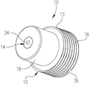
도 1은 본 발명의 한 실시예에 따른 에너지 전달 장치의 투시도;
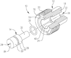
도 2는 도 1의 에너지 전달 장치의 2-부분 구조를 분해하여 예시한 투시도;
도 3은 시간 지연 퓨즈와 함께 다운홀(downhole) 공구 내에 사용되는 에너지 전달 장치의 개략도;
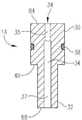
도 4는 사전-발사 형상에 있는 에너지 전달 장치 인서트의 횡단면도;
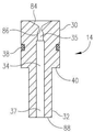
도 5는 발사-후의 에너지 전달 장치 인서트의 횡단면도로서, 수축된 통로의 형태와 인서트의 변형을 보여준다. 1 is a perspective view of an energy delivery device according to one embodiment of the present invention;
FIG. 2 is a perspective view explaining a two-part structure of the energy transfer device of FIG. 1; FIG.
Figure 3 is a schematic diagram of an energy transfer device used in a downhole tool with a time delay fuse;
4 is a cross-sectional view of an energy transfer device insert in a pre-launch configuration;
Figure 5 is a cross-sectional view of an after-launch energy transfer insert showing the shape of the retracted passage and the deformation of the insert.
이제, 특히, 도 1과 2를 보면, 본 발명의 한 실시예에 따른 에너지 전달 장치(10)가 도시된다. 전달 장치(10)는, 시간 지연 퓨즈(time delay fuse)의 폭발 출력(detonating output)을 제한하고 전환하도록 구성된 동적 장치(dynamic device) 또는 상기 출력이 또 다른 시간 지연 퓨즈를 점화시키기에 적합한 유사 장치 또는 입력(input)에 손상을 미치지 않지만 점화하는데 실패하는 유사 장치이다. 이러한 전달 장치(10)는 장치 하우징(12)과 장치 인서트(14)를 포함하는 2-부분 구조로 형성된다. 하우징(12)은 또 다른 파이로테크닉 장치(pyrotechnic device)에 전달되어야 하는 에너지를 공급하는 파이로테크닉 장치를 향해 근접하게 배열되게끔 구성된 통상 원통형의 전방 섹션(16)과 전달된 에너지를 수용하는 파이로테크닉 장치를 향해 근접하게 배열되게끔 구성된 통상 원통형의 후미 섹션(18)을 포함하는 금속성 본체(13)를 포함한다. 특정 실시예들에서, 전방 섹션(16)은 후미 섹션(18)보다 더 큰 외측 직경을 가질 수 있다. 전방 섹션(16)의 외측 표면은, 가령, 다운홀 폭파 공정(downhole blasting operation)에 사용될 수 있는 것과 같이, 하우징(12)이 공구 내에 고정될 수 있도록 하는 스레드(20)를 포함한다. 본체(13)는 내부를 통해 연장되는 축방향 보어(22)를 포함하는데, 상기 축방향 보어는 장치 인서트(14)를 수용하도록 크기가 형성된다. 보어(22)는 전방 세그먼트(24)와 후미 세그먼트(26)를 포함하며, 상기 전방 세그먼트(24)는 일반적으로 후미 세그먼트(26)보다 더 큰 직경을 가지지만, 모든 경우에 반드시 그러할 필요는 없다. Turning now in particular to Figures 1 and 2, an
장치 인서트(14)는 전방 섹션(30)과 후미 섹션(32)을 포함하는 금속성 부재(28)를 포함한다. 전방 섹션(30)은 보어(22)의 전방 세그먼트(24) 내에 수용될 수 있도록 구성되며, 후미 섹션(32)은 보어(22)의 후미 세그먼트(24) 내에 수용될 수 있도록 구성된다. 도 4에 가장 잘 도시된 것과 같이, 인서트(14)는 각각의 전방 및 후미 세그먼트(35, 37)를 포함하는 내부를 통해 연장되는 중앙의 축방향 통로(34)를 추가로 포함한다. 특정 실시예들에서, 전방 세그먼트(35)는 세그먼트(37)의 길이보다 더 짧은 길이를 가질 수 있다. 게다가, 세그먼트(35)의 직경은 세그먼트(37)의 직경보다 더 작다. The
밑에서 보다 상세하게 논의되는 것과 같이, 통로(34)는 출력 에너지가 전방 섹션(16 및 30)에 근접하게 위치된 제1 파이로테크닉 장치로부터 후미 섹션(18 및 32)에 근접하게 위치된 제2 파이로테크닉 장치를 향해 안내되는(directing) 도관으로서 작동한다. 장치 인서트(14)의 전방 섹션(30)은 O-링(38)을 수용하도록 구성된 주변 채널(36)을 포함한다. 0-링(38)은 인서트(14)와 하우징(12) 사이에 밀봉부(seal)를 제공하며 장치(10)의 조립 시에 인서트(14)가 보어(22) 내에 유지되게 하도록 보조한다. As discussed in more detail below, the
인서트(14)의 전방 섹션(30)은 일반적으로 후미 섹션(32)보다 더 큰 직경을 가지며, 따라서 보어(22)의 통상적인 형상과 상응한다. 전방 섹션(30)과 후미 섹션(32) 사이의 이음부(junction)는 숄더(40)를 포함하는데, 상기 숄더(40)는 하우징의 후미 섹션(18)과 전방 섹션(16) 사이의 이음부를 형성하는 유사하게 형성된 숄더(42)와 접한다. 두 숄더(40, 42)가 접촉 결합(contacting engagement)됨으로써, 인서트(14)와 하우징(12)의 적절한 짝 결합(mating)이 보장된다. The
특정 실시예들에서, 하우징(12)과 인서트(14)는 다양한 금속, 가령, 스테인리스 스틸로 제작될 수 있는데, 각각의 피스(piece)를 위해 상이한 스테인리스 스틸 합금도 개별적으로 선택될 수 있다. 한 특정 실시예에서, 하우징(12)은 17-4(AMS 5643) 스테인리스 스틸을 포함할 수 있으며, 인서트(14)는 304 또는 304L 스테인리스 스틸을 포함할 수 있다. 바람직한 실시예들에서, 인서트(14)는 하우징(12)이 형성되는 금속보다 더 낮은 경도 및 인장 강도 값을 가진 금속을 포함한다. 밑에서 보다 상세하게 설명되는 것과 같이, 상이한 재료로 인서트(14)와 하우징(12)을 제작하면, 제1 파이로테크닉 장치가 발사될 때 인서트(14)는 변형될 수 있는 반면 하우징(12)은 변형에 저항하여(resist) 이에 따라 재사용할 수 있게 된다. 또한, 장치(10)는 그 자체로는 임의의 파이로테크닉 재료(pyrotechnic material)를 포함하지 않는다는 사실에 유의해야 한다. In certain embodiments, the
본 명세서에 기술되고 예시된 장치(10)의 실시예들이 2-부분 구조로 구성되었지만, 중앙의 축방향 통로 및 일체형 본체를 포함하는 단일-부분 구조로 구성될 수 있는 장치(10)도 본 발명의 범위 내에 있다. 이러한 단일-부분 구조의 장치는 하우징(12)의 외부 형상 및 인서트(14)의 내부 형상, 즉 위에서 기술된 통로(34)를 보유해야 할 것이다. Although the embodiments of the
도 3에 도시된 것과 같이, 에너지 전달 장치(10)는 다운홀 폭파 공정에 사용하기 위해 공구(44), 가령, 발사 헤드(firing head) 내에 설치될 수 있다. 이에 따라, 공구(44)는 다운홀 파이프 스트링(downhole pipe string) 또는 그 외의 다른 다운홀 공구에 결부되도록 구성될 수도 있다. 공구(44)는 일반적으로 발사 핀(50)이 구비된 발사 헤드(48)를 포함하는 발사 섹션(46)을 포함한다. 발사 섹션(46)은 발사 섹션 안에 형성된 보어(54) 내에 배열된 제1 시간 지연 퓨즈(52)를 추가로 포함한다. 퓨즈(52)는 일반적으로 프라이머(56), 하나 또는 그 이상의 시간 지연(58), 및 출력 차지(60)를 포함한다. 특정 실시예들에서, 출력 차지(60)는 2,2', 4,4', 6,6'-헥사니트로스틸벤(FTNS-II)을 포함할 수도 있다. 퓨즈(52) 내에 포함될 수 있는 그 밖의 구성요소들은 점화 조성물(ignition composition)(62), 점화 차지(64), 및 전달 차지(66) 중 하나 또는 그 이상의 섹션들을 포함한다. 또한, 발사 섹션(46)은 공구 전달 섹션(72)의 외부적으로 스레드구성된(externally threaded) 영역(70)에 결부시키도록 구성된 내부적으로 스레드구성된(internally threaded) 단부 영역(68)을 포함한다. As shown in Figure 3, the
에너지 전달 장치(10)는 상기 영역(70) 내에 수용된다. 장치(10)의 스레드(20)는 영역(70)의 상응하는 스레드(74)와 짝을 이루어(mate) 장치(10)를 내부에 고정시키도록 구성된다. 장치 하우징(12)은 전방 섹션(16)의 한 면에 형성된 한 쌍의 슬롯(76)을 추가로 포함할 수 있으며, 상기 슬롯들은 장치(10)를 섹션(70) 내에 설치하는데 사용되는 공구를 수용하도록 구성된다. 장치 하우징(12)의 후미 섹션(18)에 근접하게 위치되고 전달 섹션(72) 내에 형성된 보어(80) 내에 제2 시간 지연 퓨즈(78)가 수용된다. 상기 퓨즈(78)는 퓨즈(52)와 동일하게 구성될 수 있거나, 혹은 상이하게, 가령, 더 크거나 더 작은 시간 지연(58)을 가진 상태로 구성될 수도 있다. 에너지 전달 장치(10)로부터 맞은편에 있는 단부에서, 전달 섹션(72)은 단부 영역(68)의 형상과 비슷한 내부적으로 스레드구성된 단부 영역(82)을 포함한다. 단부 영역(82)은, 추가적인 전체 시간 지연인 필요한 경우, 추가적인 전달 섹션(72)에 결부시키도록 구성된다. 대안으로, 또 다른 타입의 파이로테크닉 차지, 가령, 폭파 공정을 위한 작동 폭발물(working explosive)이 단부 영역(82)과 결합될 수 있다. The
공구(44)의 작동 동안, 발사 헤드(48)가 당업자에게 알려져 있는 임의의 수단에 따라 작동되어 발사 핀(50)을 시간 지연 퓨즈(52)를 향해 구동하게 된다. 발사 핀(50)은 프라이머(56)를 타격하여 퓨즈(52)를 점화시킨다. 퓨즈(52)가 포함되어 있는 파이로테크닉 재료(pyrotechnic material)는 출력 차지(60)를 통해 지속적으로 연소된다. 출력 차지(60)가 폭발되면(detonation) 열, 가스, 및/또는 고체 입자를 릴리스하여(release), 에너지 전달 장치를 향해, 특히, 전방 섹션(16 및 30)의 각각의 면들을 향해 안내된다. 출력 차지(60)에 의해 생성된 고온의 가스는 통로 전방 세그먼트(35)를 통해 안내되어 통로 후미 세그먼트(37)를 통해 장치(10)로부터 배출된다. 위에 기술된 것과 같이, 장치 인서트(14)는 출력 차지(60)에 의해 릴리스되는 가스 및 열에 의해 변형되는 재료로 형성될 수 있으며, 하우징(12)은 퓨즈(52)의 출력에 의해 변형되는 보다 저항적인 재료로 형성될 수 있다. 이에 따라, 출력 차지(60)가 폭발될 때, 에너지, 고온의 가스 및/또는 고체들이 인서트(14)를 향해 안내되어 인서트의 전방 섹션(30)이 변형하게 된다. 이러한 변형은 도 5에 도시된다. During operation of the
특히, 초기에 평면인 전방 섹션(30)의 면(84)이 변형되어, 통로 전방 세그먼트(35)의 직경이 좁아지고 내부에 수축부(constriction)(86)가 형성된다. 한 대표적인 실시예에서, 통로 전방 세그먼트(35)는 0.094 인치의 초기 직경을 가진다. 일반적인 주변 온도(ambient temperature)에서, 시간 지연 퓨즈 폭발 출력은 인서트 재료를 변형시켜 통로 전방 세그먼트의 직경을 약 0.040-0.050 인치 사이로 감소시킨다. 상승된 온도에서, 시간 지연 퓨즈의 출력은 스틸 테스트 덴트 블록(dent block)에서 25% 더 깊은 덴트(dent)를 형성하며, 인서트 포트 직경을 0.030-0.039 인치로 감소시킨다. 시간 지연 퓨즈가 출력되면, 통로 개방 영역은 폭발 강도(detonation strength)에 따라 3.5 내지 9.8배 감소된다. 사용 시에, 그리고, 도너(donor) 폭발 장치(예컨대, 퓨즈(52))에 의해 작동될 때, 인서트(14)의 변형/덴트는 폭발 에너지(detonation energy)의 일부분을 흡수한다. 인서트(14)의 기하학적 형상(geometry) 및 재료 특성으로 인해, 폭발 출력에 근접하게 사용될 때 통로 전방 세그먼트(35)가 부분적으로 밀폐되어(partial closing) 스틸에 덴트를 야기할 수 있다. 강력하게 폭발되면 더 많이 변형하게 되고 이에 따라 통로 전방 세그먼트(35)가 더 작은 직경으로 밀폐되며 폭발 충격(detonation impact)을 추가로 제한되어, 충분한 점화 가스 및 입자가 통과할 수 있게 하는 것이 밝혀졌다. 따라서, 이러한 작용은 도너 폭발 장치(donor detonating device)의 현재 파워 출력 레벨(power output level)을 자체-조정한다(self-regulating). In particular, the initially
통로 전방 세그먼트(35)의 수축부(86)로 인해, 출력 차지(60)로부터의 압력(예컨대, HNS-II, 아지드(azide) 출력 에너지 및 출력 개시 에너지(output initiator energy), 고온의 금속 단편(fragment), 용융 금속 및 슬래그(slag)로부터의 폭발 압력 및 열의 조합)이 더 긴 시간 동안 릴리스될 수 있게 한다. HNS-II로부터의 변형되면, 종종 면(84)의 변형 후에 슬래그로 덮히는 원뿔형 임프레션(conical impression)을 생성한다. HNS-II가 폭발되면, 보통, 검정 검댕(soot)을 남기며, 따라서, 특정 실시예들에서, 인서트(14) 내부와 인서트(14) 위에 관찰된 슬래그는 폭발로부터의 초기 충격 후에 통로(34)를 통한 가스 및 고체 흐름을 나타낸다. Due to the
장치(10)의 2-부분 구조로 인해, 하우징(12)은 단순히 인서트(14)를 교체함으로써 재사용할 수 있게 된다. 통로 후미 세그먼트(37)는 통로 전방 세그먼트(35)보다 더 큰 초기 직경을 가질 수 있다. 더 큰 직경의 세그먼트(37)는 공구 마모가 성능에 영향을 끼치지 않으며 직경과 동심도(concentricity)가 조절될 수 있도록 하는 새로운 통로(renewable passage)로서 기능을 한다(function). 그 다음 지연의 출력에 가장 가까운 영역이 보통 확장되고(expand) 재활용 공구의 일부분인 경우 마모 지점(wear point)일 수 있다는 것을 유의해야 한다. Due to the two-part structure of the
출력 차지(60)의 연소에 의해 생성된 에너지, 가스 및/또는 고체 제품(solid product)는 통로(34)를 통해 퓨즈(78)를 향해 이동된다(carried). 인서트(14)의 후미 면(88)과 반응하면, 고온의 가스 및/또는 고체는 퓨즈(78)의 프라이머(56) 상에 직접 집중되고(focused) 점화를 보장할 수 있다. 따라서, 장치(10)는 퓨즈(52)의 출력을 효율적이면서도 안정적으로 퓨즈(78)에 전달하여 발사 헤드(48)로부터 시작하는 발사 시퀀스(firing sequence)가 지속되도록 보장한다. 그 뒤, 퓨즈(78)의 출력 차지(60)는, 또 다른 전달 섹션(72)이 단부 영역(82)에 결부됨으로써, 또 다른 퓨즈에 전달될 수 있거나, 혹은 또 다른 타입의 파이로테크닉 장치, 가령, 또 다른 발사 헤드 또는 폭파 공정에 사용될 수 있는 폭발장약(explosive charge)에 전달될 수 있다. The energy, gas, and / or solid product produced by the combustion of the
Claims (31)
상기 에너지 전달 장치는 제1 파이로테크닉 장치에 근접하게 배열되도록 구성된 전방 섹션 및 제2 파이로테크닉 장치에 근접하게 배열되도록 구성된 후미 섹션을 포함하는 금속성 본체를 포함하며,
상기 금속성 본체는 내부를 통해 연장되는 축방향 통로를 추가로 포함하고, 상기 통로는 본체 전방 섹션을 통해 연장되는 제1 세그먼트와 본체 후미 섹션을 통해 연장되는 제2 세그먼트를 포함하며,
상기 본체 전방 섹션은 통로 제1 세그먼트의 직경이 좁아져서 통로 내에 수축부가 형성되도록 제1 파이로테크닉 장치로부터의 에너지 출력에 의해 변형될 수 있는 것을 특징으로 하는 에너지 전달 장치. An energy delivery device configured to transfer energy output from a first pyrotechnic device to a second pyrotechnic device to initiate firing of a second pyrotechnic device.
The energy transfer device comprising a metallic body comprising a front section configured to be arranged close to the first pyrotechnic device and a rear section configured to be arranged close to the second pyrotechnic device,
The metallic body further comprising an axial passage extending through the interior, the passage including a first segment extending through the body front section and a second segment extending through the body rear section,
Wherein the body front section is deformable by an energy output from the first pyrotechnic device so that the diameter of the first passageway segment is reduced to create a contraction in the passageway.
상기 에너지 전달 장치는:
- 내부를 통해 연장되는 중앙 보어를 포함하는 장치 하우징을 포함하고, 상기 하우징은 하우징 전방 섹션과 하우징 후미 섹션을 포함하며;
- 상기 하우징에 의해 상기 보어 내로 수용되는(carried) 장치 인서트를 포함하고, 상기 인서트는 인서트 전방 섹션과 인서트 후미 섹션 및 내부를 통해 연장되는 축방향 통로를 포함하며,
상기 하우징 전방 섹션과 인서트 전방 섹션은 제1 파이로테크닉 장치를 향해 제1 파이로테크닉 장치에 근접하게 배열되도록 구성되고, 상기 하우징 후미 섹션과 인서트 후미 섹션은 제2 파이로테크닉 장치를 향해 제2 파이로테크닉 장치에 근접하게 배열되도록 구성되며,
상기 인서트 전방 섹션은 통로 내에 수축부가 형성되도록 제1 파이로테크닉 장치로부터의 에너지 출력에 의해 변형될 수 있는 것을 특징으로 하는 에너지 전달 장치. An energy delivery device configured to transfer energy output from a first pyrotechnic device to a second pyrotechnic device to initiate firing of a second pyrotechnic device.
Wherein the energy transfer device comprises:
- a device housing including a central bore extending through the interior, the housing comprising a housing front section and a housing rear section;
A device insert carried in said bore by said housing, said insert comprising an insert front section and an insert rear section and an axial passage extending through the interior,
Wherein the housing front section and the insert front section are configured to be arranged proximate to the first pyrotechnic device toward the first pyrotechnic device and wherein the housing rear section and the insert rear section are arranged toward the second pyrotechnic device towards the second pyrotechnic device, Arranged to be close to the pyrotechnic device,
Wherein the insert front section is deformable by an energy output from the first pyrotechnic device to form a contraction in the passageway.
상기 공구는 시간 지연 퓨즈 및 에너지 전달 장치를 포함하며,
상기 에너지 전달 장치는:
- 내부를 통해 연장되는 중앙 보어를 포함하는 장치 하우징을 포함하고, 상기 하우징은 하우징 전방 섹션과 하우징 후미 섹션을 포함하며;
- 상기 하우징에 의해 상기 보어 내로 수용되는(carried) 장치 인서트를 포함하고, 상기 인서트는 인서트 전방 섹션과 인서트 후미 섹션 및 내부를 통해 연장되는 축방향 통로를 포함하며, 상기 인서트 전방 섹션은 통로 내에 수축부가 형성되도록 제1 파이로테크닉 장치로부터의 에너지 출력에 의해 변형될 수 있는 것을 특징으로 하는 파이로테크닉 차지를 전달하기 위한 공구. A tool for delivering a pyrotechnic charge to a downhole in a well,
The tool comprising a time delay fuse and an energy delivery device,
Wherein the energy transfer device comprises:
- a device housing including a central bore extending through the interior, the housing comprising a housing front section and a housing rear section;
- a device insert carried by the housing into the bore, the insert comprising an insert front section and an insert rear section and an axial passage extending therethrough, the insert front section including a shrinkage Is deformable by an energy output from the first pyrotechnic device so as to form a part of the pyrotechnic charge.
상기 방법은:
- 제1 파이로테크닉 장치, 에너지 전달 장치, 및 제2 파이로테크닉 장치를 제공하는 단계를 포함하고, 상기 에너지 전달 장치는 전방 섹션, 후미 섹션, 및 내부를 통해 연장되는 축방향 통로를 가진 금속성 본체를 포함하며;
- 제1 파이로테크닉 장치를 점화시켜 출력 차지를 폭발시키는 단계를 포함하고;
- 상기 출력 차지의 폭발로부터의 에너지의 일부분 이상을 축방향 통로를 통하여 제2 파이로테크닉 장치를 향해 안내하여 상기 제2 파이로테크닉 장치를 점화시키는 단계를 포함하는 것을 특징으로 하는 파이로테크닉 차지를 점화하기 위한 방법. A method for igniting a pyrotechnic charge in a downhole in a well,
The method comprising:
- providing a first pyrotechnic device, an energy transfer device, and a second pyrotechnic device, the energy transfer device comprising a metallic section having a front section, a trailing section, and an axial passage extending through the interior, A body;
Igniting the first pyrotechnic device to explode the output charge;
- guiding at least a portion of the energy from the explosion of the output charge through the axial passage towards the second pyrotechnic device to ignite the second pyrotechnic device / RTI >
Applications Claiming Priority (3)
| Application Number | Priority Date | Filing Date | Title |
|---|---|---|---|
| US201261637541P | 2012-04-24 | 2012-04-24 | |
| US61/637,541 | 2012-04-24 | ||
| PCT/US2013/032243 WO2014007864A2 (en) | 2012-04-24 | 2013-03-15 | Energy transfer device |
Publications (1)
| Publication Number | Publication Date |
|---|---|
| KR20150010733A true KR20150010733A (en) | 2015-01-28 |
Family
ID=49379063
Family Applications (1)
| Application Number | Title | Priority Date | Filing Date |
|---|---|---|---|
| KR1020147031820A KR20150010733A (en) | 2012-04-24 | 2013-03-15 | Energy transfer device |
Country Status (15)
| Country | Link |
|---|---|
| US (3) | US8943970B2 (en) |
| EP (1) | EP2841688B1 (en) |
| JP (1) | JP6145159B2 (en) |
| KR (1) | KR20150010733A (en) |
| CN (1) | CN104541020B (en) |
| AU (1) | AU2013287267B2 (en) |
| BR (1) | BR112014026471A2 (en) |
| CA (1) | CA2880348C (en) |
| DK (1) | DK2841688T3 (en) |
| HK (2) | HK1205223A1 (en) |
| HU (1) | HUE038750T2 (en) |
| IN (1) | IN2014DN09728A (en) |
| MX (1) | MX347896B (en) |
| RU (1) | RU2634960C2 (en) |
| WO (1) | WO2014007864A2 (en) |
Families Citing this family (22)
| Publication number | Priority date | Publication date | Assignee | Title |
|---|---|---|---|---|
| CN104541020B (en) | 2012-04-24 | 2017-04-12 | 法克有限公司 | Energy transfer device |
| US9500419B2 (en) | 2013-03-15 | 2016-11-22 | Hypersciences, Inc. | Ram accelerator system |
| US9458670B2 (en) | 2014-05-13 | 2016-10-04 | Hypersciences, Inc. | Ram accelerator system with endcap |
| US9784548B2 (en) | 2014-05-14 | 2017-10-10 | Fike Corporation | Vented-at-temperature igniter |
| US9988844B2 (en) | 2014-10-23 | 2018-06-05 | Hypersciences, Inc. | Ram accelerator system with rail tube |
| US10697242B2 (en) | 2015-04-21 | 2020-06-30 | Hypersciences, Inc. | Ram accelerator system with baffles |
| US10557308B2 (en) | 2015-11-10 | 2020-02-11 | Hypersciences, Inc. | Projectile drilling system |
| US10329842B2 (en) | 2015-11-13 | 2019-06-25 | Hypersciences, Inc. | System for generating a hole using projectiles |
| US11156067B2 (en) * | 2016-02-11 | 2021-10-26 | Hunting Titan, Inc. | Detonation transfer system |
| CN106091838B (en) * | 2016-06-17 | 2018-01-02 | 雅化集团绵阳实业有限公司 | A kind of high-power priming device |
| US10590707B2 (en) | 2016-09-12 | 2020-03-17 | Hypersciences, Inc. | Augmented drilling system |
| DE202017102257U1 (en) * | 2017-04-13 | 2017-06-20 | Fr. Sobbe Gmbh | Ignition device in compact version |
| US10837747B2 (en) * | 2018-02-15 | 2020-11-17 | Goodrich Corporation | High explosive firing mechanism |
| US11408279B2 (en) | 2018-08-21 | 2022-08-09 | DynaEnergetics Europe GmbH | System and method for navigating a wellbore and determining location in a wellbore |
| US10927627B2 (en) | 2019-05-14 | 2021-02-23 | DynaEnergetics Europe GmbH | Single use setting tool for actuating a tool in a wellbore |
| US11255147B2 (en) | 2019-05-14 | 2022-02-22 | DynaEnergetics Europe GmbH | Single use setting tool for actuating a tool in a wellbore |
| US11578549B2 (en) | 2019-05-14 | 2023-02-14 | DynaEnergetics Europe GmbH | Single use setting tool for actuating a tool in a wellbore |
| US11204224B2 (en) | 2019-05-29 | 2021-12-21 | DynaEnergetics Europe GmbH | Reverse burn power charge for a wellbore tool |
| EP3999712A1 (en) | 2019-07-19 | 2022-05-25 | DynaEnergetics Europe GmbH | Ballistically actuated wellbore tool |
| US11624235B2 (en) | 2020-08-24 | 2023-04-11 | Hypersciences, Inc. | Ram accelerator augmented drilling system |
| US11719047B2 (en) | 2021-03-30 | 2023-08-08 | Hypersciences, Inc. | Projectile drilling system |
| US11753889B1 (en) | 2022-07-13 | 2023-09-12 | DynaEnergetics Europe GmbH | Gas driven wireline release tool |
Family Cites Families (45)
| Publication number | Priority date | Publication date | Assignee | Title |
|---|---|---|---|---|
| US2561670A (en) * | 1945-07-30 | 1951-07-24 | Aerojet Engineering Corp | Ignitor |
| US2934014A (en) * | 1956-12-06 | 1960-04-26 | Rex L Smith | Igniter assemblies |
| US3209692A (en) * | 1964-10-05 | 1965-10-05 | Avco Corp | Explosion transfer device |
| FR1552100A (en) | 1967-11-17 | 1969-01-03 | ||
| US3578011A (en) * | 1969-01-29 | 1971-05-11 | Us Army | Pyro fluidic relay |
| US3945322A (en) * | 1974-04-05 | 1976-03-23 | The United States Of America As Represented By The Secretary Of The Navy | Through-bulkhead explosion initiation |
| US3982488A (en) * | 1975-02-19 | 1976-09-28 | The United States Of America As Represented By The Secretary Of The Army | Flueric through bulkhead rocket motor ignitor |
| US4060033A (en) * | 1976-03-09 | 1977-11-29 | Atlas Powder Company | Delay booster assembly |
| US4060034A (en) * | 1976-03-09 | 1977-11-29 | Atlas Powder Company | Delay booster assembly |
| US4144814A (en) * | 1976-07-08 | 1979-03-20 | Systems, Science And Software | Delay detonator device |
| US4033267A (en) * | 1976-10-01 | 1977-07-05 | The United States Of America As Represented By The Secretary Of The Navy | Flueric cartridge initiator |
| DE2648137C2 (en) * | 1976-10-23 | 1984-04-12 | Dynamit Nobel Ag, 5210 Troisdorf | Propellant charge lighter for ammunition |
| US4165691A (en) * | 1977-08-29 | 1979-08-28 | Atlas Powder Company | Delay detonator and its use with explosive packaged boosters and cartridges |
| US4178852A (en) * | 1977-08-29 | 1979-12-18 | Atlas Powder Company | Delay actuated explosive device |
| US4135454A (en) * | 1977-09-14 | 1979-01-23 | The United States Of America As Represented By The Secretary Of The Navy | Safing a flueric cartridge initiator |
| US4377592A (en) | 1979-10-23 | 1983-03-22 | Innothera | Antiarrhythmic activity of cetiedil |
| DE3415680A1 (en) * | 1983-12-30 | 1985-07-11 | Dynamit Nobel Ag, 5210 Troisdorf | COMPRESSED GAS ACTUATED MECHANICAL POWER ELEMENT |
| US4653400A (en) * | 1985-07-03 | 1987-03-31 | The United States Of America As Represented By The Secretary Of The Army | Two component thru-bulkhead initiator |
| SE456528B (en) * | 1986-02-17 | 1988-10-10 | Nobel Kemi Ab | TENDARE |
| US4856433A (en) * | 1987-07-13 | 1989-08-15 | Scot, Incorporated | Initiator device with adiabatic compression ignition |
| US4938141A (en) * | 1989-06-19 | 1990-07-03 | Honeywell Inc. | Shock initiator device for initiating a percussion primer |
| US5435248A (en) * | 1991-07-09 | 1995-07-25 | The Ensign-Bickford Company | Extended range digital delay detonator |
| US5173569A (en) * | 1991-07-09 | 1992-12-22 | The Ensign-Bickford Company | Digital delay detonator |
| US5780764A (en) * | 1996-01-11 | 1998-07-14 | The Ensign-Bickford Company | Booster explosive devices and combinations thereof with explosive accessory charges |
| US5614693A (en) * | 1996-01-11 | 1997-03-25 | The Ensign-Bickford Company | Accessory charges for booster explosive devices |
| US5703320A (en) * | 1996-01-18 | 1997-12-30 | The Ensign Bickford Company | Connector for blast initiation system |
| CA2230574C (en) * | 1997-02-26 | 2005-12-20 | Alliant Techsystems Inc. | Through bulkhead initiator |
| CN2343339Y (en) * | 1998-03-03 | 1999-10-13 | 四川石油管理局测井公司 | Pressure exploder with shear pin handy to mounting or detaching |
| SE516812C2 (en) * | 1999-09-06 | 2002-03-05 | Dyno Nobel Sweden Ab | Explosive capsule, procedure for ignition of base charge and initiation element for explosive capsule |
| RU2186951C1 (en) * | 2000-11-24 | 2002-08-10 | Мамарин Геннадий Феофанович | Downhole jet perforator |
| FR2817955B1 (en) * | 2000-12-13 | 2003-05-16 | Giat Ind Sa | PRIMING DEVICE FOR EXPLOSIVE CHARGE AND FORMED CHARGE INCORPORATING SUCH A PRIMING DEVICE |
| WO2002085818A2 (en) * | 2001-04-24 | 2002-10-31 | The Ensign-Bickford Company | Non-electric detonator |
| RU2215127C2 (en) * | 2001-11-09 | 2003-10-27 | Федеральное государственное унитарное предприятие Комбинат "Электрохимприбор" | Well hollow-carrier jet-type perforator |
| US6644099B2 (en) * | 2001-12-14 | 2003-11-11 | Specialty Completion Products | Shaped charge tubing cutter performance test apparatus and method |
| CN1443925A (en) * | 2002-03-08 | 2003-09-24 | 东营市万通胜利测井技术开发有限责任公司 | Double-layer gun high-effective perforator |
| RU2233428C1 (en) * | 2003-05-05 | 2004-07-27 | Федеральное государственное унитарное предприятие "Комбинат "Электрохимприбор" | Detonating device of mechanical fuse |
| SE0302916D0 (en) * | 2003-11-04 | 2003-11-04 | Comtri Teknik Ab | Replaceable drive cartridge |
| MX2007010283A (en) * | 2005-02-23 | 2008-03-13 | Dale Seekford | Method and apparatus for stimulating wells with propellants. |
| US8079296B2 (en) * | 2005-03-01 | 2011-12-20 | Owen Oil Tools Lp | Device and methods for firing perforating guns |
| US7987787B1 (en) * | 2007-03-07 | 2011-08-02 | Ensign-Bickford Aerospace & Defense Company | Electronic ignition safety device configured to reject signals below a predetermined ‘all-fire voltage’ |
| US8151708B2 (en) | 2008-02-08 | 2012-04-10 | Pacific Scientific Energetic Materials Company | Safe and arm mechanisms and methods for explosive devices |
| AU2011224469B2 (en) | 2010-03-09 | 2014-08-07 | Dyno Nobel Inc. | Sealer elements, detonators containing the same, and methods of making |
| WO2012006357A2 (en) * | 2010-07-06 | 2012-01-12 | Schlumberger Canada Limited | Ballistic transfer delay device |
| US8561683B2 (en) * | 2010-09-22 | 2013-10-22 | Owen Oil Tools, Lp | Wellbore tubular cutter |
| CN104541020B (en) * | 2012-04-24 | 2017-04-12 | 法克有限公司 | Energy transfer device |
-
2013
- 2013-03-15 CN CN201380022106.5A patent/CN104541020B/en not_active Expired - Fee Related
- 2013-03-15 AU AU2013287267A patent/AU2013287267B2/en not_active Ceased
- 2013-03-15 EP EP13813356.6A patent/EP2841688B1/en active Active
- 2013-03-15 CA CA2880348A patent/CA2880348C/en active Active
- 2013-03-15 HU HUE13813356A patent/HUE038750T2/en unknown
- 2013-03-15 RU RU2014142999A patent/RU2634960C2/en not_active IP Right Cessation
- 2013-03-15 US US13/833,723 patent/US8943970B2/en not_active Expired - Fee Related
- 2013-03-15 KR KR1020147031820A patent/KR20150010733A/en not_active Application Discontinuation
- 2013-03-15 WO PCT/US2013/032243 patent/WO2014007864A2/en active Application Filing
- 2013-03-15 JP JP2015508970A patent/JP6145159B2/en active Active
- 2013-03-15 DK DK13813356.6T patent/DK2841688T3/en active
- 2013-03-15 MX MX2014012789A patent/MX347896B/en active IP Right Grant
- 2013-03-15 BR BR112014026471A patent/BR112014026471A2/en not_active IP Right Cessation
-
2014
- 2014-11-18 IN IN9728DEN2014 patent/IN2014DN09728A/en unknown
-
2015
- 2015-01-29 US US14/609,151 patent/US9476686B2/en active Active
- 2015-06-19 HK HK15105861.8A patent/HK1205223A1/en unknown
- 2015-07-17 HK HK15106818.0A patent/HK1206407A1/en unknown
-
2016
- 2016-09-22 US US15/272,534 patent/US9963398B2/en active Active
Also Published As
| Publication number | Publication date |
|---|---|
| CN104541020A (en) | 2015-04-22 |
| CN104541020B (en) | 2017-04-12 |
| US20130277108A1 (en) | 2013-10-24 |
| RU2014142999A (en) | 2016-06-10 |
| JP6145159B2 (en) | 2017-06-07 |
| RU2634960C2 (en) | 2017-11-08 |
| US9476686B2 (en) | 2016-10-25 |
| MX347896B (en) | 2017-05-18 |
| US20170008819A1 (en) | 2017-01-12 |
| HK1205223A1 (en) | 2015-12-11 |
| AU2013287267B2 (en) | 2017-08-17 |
| WO2014007864A2 (en) | 2014-01-09 |
| HK1206407A1 (en) | 2016-01-08 |
| HUE038750T2 (en) | 2018-11-28 |
| WO2014007864A3 (en) | 2014-03-06 |
| CA2880348A1 (en) | 2014-01-09 |
| EP2841688B1 (en) | 2018-05-09 |
| AU2013287267A1 (en) | 2014-11-13 |
| EP2841688A2 (en) | 2015-03-04 |
| DK2841688T3 (en) | 2018-07-30 |
| US8943970B2 (en) | 2015-02-03 |
| CA2880348C (en) | 2019-09-24 |
| IN2014DN09728A (en) | 2015-07-31 |
| BR112014026471A2 (en) | 2017-06-27 |
| EP2841688A4 (en) | 2015-12-02 |
| US20150144399A1 (en) | 2015-05-28 |
| JP2015518133A (en) | 2015-06-25 |
| MX2014012789A (en) | 2015-01-22 |
| US9963398B2 (en) | 2018-05-08 |
Similar Documents
| Publication | Publication Date | Title |
|---|---|---|
| US9963398B2 (en) | Energy transfer device | |
| US5765923A (en) | Cartridge for generating high-pressure gases in a drill hole | |
| EP2856067B1 (en) | Pressure relief system for cartridge munition | |
| US3491692A (en) | Multi-stage rocket | |
| CN204457597U (en) | Bridging plug gunpowder structure | |
| EP3527930B1 (en) | Low energy explosive transfer adapter | |
| CN101629795A (en) | Detonating of ignition booster device | |
| CN104034216B (en) | Quick bursting device | |
| KR102124079B1 (en) | Non electric explosive bolt and separating apparatus for projectile using the same | |
| RU2705859C1 (en) | Separation bolt with obturation system | |
| CN209976525U (en) | Percussion detonator for oil-gas well perforation | |
| US7546805B2 (en) | Detonator | |
| WO1999053263A2 (en) | Deflagration to detonation choke | |
| US2390552A (en) | Explosive bullet | |
| US3236317A (en) | Projectile propelling apparatus for use in high temperature environment | |
| KR102534213B1 (en) | Separating bolt using shape memory alloy | |
| CN106471329A (en) | General priming device and the device based on this device | |
| JP5165332B2 (en) | Flying object | |
| EP0403640A1 (en) | Method and apparatus for detonating explosives | |
| US414389A (en) | emmens | |
| US20180274893A1 (en) | Detonator provided with a securement device | |
| GB2508412A (en) | Detonator | |
| ZA200809044B (en) | Shock-tube delay igniter | |
| PL190327B1 (en) | Practice sabot shell |
Legal Events
| Date | Code | Title | Description |
|---|---|---|---|
| E902 | Notification of reason for refusal | ||
| E601 | Decision to refuse application |