KR20150002895U - Cap for cable installation - Google Patents
Cap for cable installation Download PDFInfo
- Publication number
- KR20150002895U KR20150002895U KR2020140000362U KR20140000362U KR20150002895U KR 20150002895 U KR20150002895 U KR 20150002895U KR 2020140000362 U KR2020140000362 U KR 2020140000362U KR 20140000362 U KR20140000362 U KR 20140000362U KR 20150002895 U KR20150002895 U KR 20150002895U
- Authority
- KR
- South Korea
- Prior art keywords
- cable
- cap
- main body
- fixing
- rope
- Prior art date
Links
Images

Classifications
-
- H—ELECTRICITY
- H02—GENERATION; CONVERSION OR DISTRIBUTION OF ELECTRIC POWER
- H02G—INSTALLATION OF ELECTRIC CABLES OR LINES, OR OF COMBINED OPTICAL AND ELECTRIC CABLES OR LINES
- H02G15/00—Cable fittings
- H02G15/02—Cable terminations
- H02G15/04—Cable-end sealings
-
- H—ELECTRICITY
- H02—GENERATION; CONVERSION OR DISTRIBUTION OF ELECTRIC POWER
- H02G—INSTALLATION OF ELECTRIC CABLES OR LINES, OR OF COMBINED OPTICAL AND ELECTRIC CABLES OR LINES
- H02G1/00—Methods or apparatus specially adapted for installing, maintaining, repairing or dismantling electric cables or lines
- H02G1/14—Methods or apparatus specially adapted for installing, maintaining, repairing or dismantling electric cables or lines for joining or terminating cables
Abstract
선박에 포설되는 케이블의 선단을 보호 또는 견인하기 위한 캡으로서, 상기 케이블의 선단을 수용하는 케이블 수용부, 케이블을 고정하기 위한 다수의 고정홈과 케이블을 견인하는 견인로프가 삽입되는 로프 수용부를 구비하는 본체, 상기 본체의 케이블 수용부에 삽입되는 케이블을 상기 고정홈에서 면압으로 지지하기 위해 상기 고정홈에 장착되는 지지부를 포함하고, 상기 본체는 곡면으로 형성되는 구성을 마련하여, 케이블의 선단을 보호함과 동시에 이를 견인할 수 있으므로 전선포설의 작업능률을 향상시킬 수 있다는 효과가 있다.A cap for protecting or towing the tip of a cable installed on a ship, comprising: a cable receiving portion for receiving a tip of the cable; a plurality of fixing grooves for fixing the cable; and a rope accommodating portion for inserting a traction rope for pulling the cable And a support portion mounted on the fixing groove to support the cable inserted into the cable receiving portion of the main body by the surface pressure of the fixing groove, wherein the main body has a curved surface, It is possible to improve the working efficiency of the wire installation because it can protect and protect it.
Description
본 고안은 전선포설용 캡에 관한 것으로, 특히 케이블의 선단을 감싸 보호함과 동시에 이를 견인할 수 있는 전선포설용 캡에 관한 것이다.The present invention relates to a cap for laying a cable, and more particularly, to a cap for laying a cable while protecting the tip of the cable so as to be able to be towed.
일반적으로 전기가 흐르는 전선의 특성상 케이블의 외피가 수지재질로 이루어져 마찰력이 감소하게 된다. 이에 따라 포설시 케이블의 단부가 케이블 트레이의 지지바 사이로 빠지거나 선박의 구조물과 충돌하여 파손되는 문제가 발생했다.Generally, due to the nature of the electric wire through which electric current flows, the outer surface of the cable is made of a resin material, thereby reducing the frictional force. As a result, when the cable is installed, the end of the cable falls into the support bars of the cable tray or collides with the structure of the ship and is damaged.
또한, 이와 같이 케이블이 설치물 사이에 빠지는 경우, 케이블의 선단에 로프를 묶어서 작업자가 견인을 해야 하므로, 힘과 시간이 소요된다는 문제가 있었다.Further, in the case where the cable is pulled out between the fixtures, there is a problem that the rope is tied to the distal end of the cable and the operator has to pull the cable.
이와 같은 문제를 해결하기 위해 케이블의 단부를 납으로 봉인 또는 테이프 등으로 감싸거나 열 수축 필름 등의 보호 부재를 이용하여 보호하는 방법이 사용된다. 하지만 이 같은 경우 보호 부재를 해체하는 작업과정 중 케이블의 손상을 초래할 수 있다는 문제점이 있었다.In order to solve such a problem, a method of protecting an end portion of a cable by using a protective member such as a heat shrinkable film or the like by sealing with a lead, a tape or the like is used. However, in such a case, the cable may be damaged during the process of disassembling the protection member.
이러한 문제를 해결하기 위한 기술의 일 예가 하기 문헌 1 및 2 등에 개시되어 있다.One example of the technique for solving such a problem is described in Documents 1 and 2 below.
예를 들어, 하기 특허문헌 1에는 케이블 보호캡에 케이블 지지공이 형성된 케이블 고정구를 지지구로 고정하되 지지구의 지지턱이 케이블 보호캡의 걸림 턱에 끼워 고정되도록 한 케이블 단부 보호캡에 대해 개시되어 있다.For example, the following Patent Document 1 discloses a cable end protective cap that fixes a cable fastener having a cable support hole formed in a cable protection cap to a support so that the support jaw of the support is fitted and fastened to the fastening protrusion of the cable protection cap.
또 하기 특허문헌 2에는 케이블과 유사한 원통형상의 페롤을 보호하기 위해 구비된 보호캡에 관한 것으로, 케이블에 탈부착할 수 있는 " U " 자형 광케이블 홀더에 보호캡이 일체형으로 제작된 제품을 사용함으로써 본체의 분실방지 및 손실을 사전에 방지할 수 있는 광케이블 커넥터의 보호캡 고정 장치에 대해 개시되어 있다.Patent Document 2 discloses a protection cap provided to protect a cylindrical ferrule similar to a cable. In this case, a product in which a protective cap is integrally formed on a "U" shaped optical cable holder that can be detachably attached to a cable is used, A protection cap fixing device for an optical cable connector capable of preventing loss and preventing loss in advance is disclosed.
그러나, 상술한 바와 같은 종래의 특허문헌 1의 기술에서는 제작된 케이블을 작업장까지 이송시키는 중에 케이블 전단부 파손을 방지할 수 있다고 하더라도, 선박의 트레이에 케이블을 포설하는 구조에서 케이블을 견인하기 위해서는, 별도의 로프를 결합해야 했다.However, in the above-described conventional technique of Patent Document 1, in order to pull the cable in a structure in which a cable is installed in a tray of a ship, even if breakage of the front end of the cable can be prevented while the produced cable is being transferred to a work site, I had to combine separate ropes.
또한, 케이블의 전단부를 감싸는 보호캡이 단면으로 형성되어 견인시 작업장 내에 설치된 구조물에 부딪혀 쉽게 파손되며, 복잡한 작업장 내에서 사용하기 어렵다는 문제점을 갖는다.In addition, a protective cap for covering the front end portion of the cable is formed in a cross-section so that it is easily damaged by collision with a structure installed in a work site during pulling, which is difficult to use in a complex worksite.
한편, 상기 특허문헌 2에 있어서는 케이블 홀더와 일체로 형성되는 연결밴드와 일체로 형성되는 보호캡이 모자를 쓰듯이 패롤에 씌워서 손쉽게 패롤을 보호할 수 있지만, 선박의 케이블 트레이의 포설장치에는 적용할 수가 없고, 케이블 끝단에 로프를 묶어서 당기는 경우 힘의 중심부가 케이블의 측면에 있으므로, 케이블의 견인이 한쪽으로 치우친다는 문제도 있었다.On the other hand, in Patent Document 2, the protective cap integrally formed with the connection band integrally formed with the cable holder can be easily covered with the cap so as to protect the parole, but can be applied to a cable tray installation apparatus There is also a problem that when pulling the rope at the end of the cable, the center of the force is on the side of the cable, and the pulling of the cable is shifted to one side.
또한, 보호캡을 선박이나 케이블에 적용하는 경우 더욱 쉽게 벗겨질 수 있으며, 끝단이 단면으로 형성됨에 따라 케이블을 보호하는 효과가 떨어진다는 문제점을 갖는다.In addition, when the protective cap is applied to a ship or a cable, it can be easily peeled off, and the end is formed in a cross-sectional shape, so that the effect of protecting the cable is deteriorated.
본 고안의 목적은 상술한 바와 같은 문제점을 해결하기 위해 이루어진 것으로서, 구조물과 충돌 시 충격을 완화하여 케이블 단부를 보호 및 경로 형성이 용이하도록 저마찰계수를 가지는 재질의 원뿔형상 및 원통형상으로 이루어진 전선포설용 캡을 제공하는 것이다.The object of the present invention is to solve the above-mentioned problems, and it is an object of the present invention to provide a wire having a conical shape and a cylindrical shape of a material having a low coefficient of friction so as to facilitate protection of a cable end, Thereby providing a mounting cap.
또 본 고안의 다른 목적은 포설중 케이블의 중심부에서 케이블을 견인할 수 있는 전선포설용 캡을 제공하는 것이다.Another object of the present invention is to provide a cable-laying cap capable of pulling a cable at the center of the cable during installation.
또한, 본 고안의 다른 목적은 다양한 직경의 케이블을 보호하면서 견인할 수 있는 전선포설용 캡을 제공하는 것이다.Another object of the present invention is to provide a cable laying cap capable of towing while protecting cables of various diameters.
상기 목적을 달성하기 위해 본 고안에 따른 전선포설용 캡은 선박에 포설되는 케이블의 선단을 보호 또는 견인하기 위한 캡으로서, 상기 케이블의 선단을 수용하는 케이블 수용부, 케이블을 고정하기 위한 다수의 고정홈과 케이블을 견인하는 견인로프가 삽입되는 로프 수용부를 구비하는 본체, 상기 본체의 케이블 수용부에 삽입되는 케이블을 상기 고정홈에서 면압으로 지지하기 위해 상기 고정홈에 장착되는 지지부를 포함하고, 상기 본체는 곡면으로 형성된 것을 특징으로 한다.In order to accomplish the above object, according to the present invention, there is provided a cap for protecting or pulling a cable installed on a ship, comprising: a cable receiving portion for receiving a tip of the cable; A main body having a rope accommodating portion into which a traction rope for retracting a groove and a cable is inserted; and a support mounted on the fixing groove to support a cable inserted into the cable receiving portion of the main body by surface pressure, And the main body is formed of a curved surface.
상기 본체는 작업장 내 구조물과 충돌하는 경우 충격이 케이블의 선단에 전달되는 것을 감소시키도록 상기 케이블 수용부가 상기 로프 수용부 보다 작은 구배를 가지도록 형성되며, 미끄러짐이 원활하도록 저마찰계수를 가지는 수지재질로 제작된 것을 특징으로 한다.The main body is formed to have a smaller gradient than the rope accommodating portion so as to reduce the transmission of the impact to the front end of the cable when colliding with the structure in the work area, and is made of a resin material having a low friction coefficient As shown in FIG.
상기 로프 수용부는 상기 케이블 수용부의 중앙 부분에 마련된 것을 특징으로 한다.And the rope accommodating portion is provided at a central portion of the cable accommodating portion.
상기 지지부는 상기 본체에 대해 90도 간격으로 돌출되지 않게 장착되고 끝단에서 면압으로 상기 케이블을 지지하는 고정볼트를 구비하는 것을 특징으로 한다.And the support portion includes a fixing bolt mounted to the main body so as not to protrude at intervals of 90 degrees and to support the cable by surface pressure at an end thereof.
상기 본체는 케이블 수용부의 공간보다 큰 직경의 케이블이 결합될 수 있도록 상부캡과 하부캡으로 분할된 것을 특징으로 한다.And the main body is divided into an upper cap and a lower cap so that a cable having a diameter larger than a space of the cable receiving portion can be coupled.
상기 본체에는 상기 상부캡과 하부캡을 관통하도록 형성된 관통구가 형성된 것을 특징으로 한다.And a through hole formed to penetrate the upper cap and the lower cap is formed in the main body.
상술한 바와 같이, 본 고안에 따른 전선포설용 캡에 의하면, 본체 내부로 케이블과 견인로프를 삽입하는 구성을 마련하는 것에 의해 케이블의 선단을 보호함과 동시에 이를 견인할 수 있으므로 전선포설의 작업능률을 향상시킬 수 있다는 효과가 있다.As described above, according to the cap for laying the wire according to the present invention, since the cable and the pulling rope are inserted into the main body, the tip of the cable can be protected and towed, Can be improved.
또 본 고안에 따른 전선포설용 캡에 의하면, 본체가 원뿔형상으로 구배진 곡선과 잘 미끄러지는 표면재질을 갖기 때문에 장애물과 충돌 시 충격을 줄여 케이블의 선단을 효과적으로 보호할 수 있으며, 케이블 전단부의 경로 형성이 보다 용이할 수 있다는 효과도 얻어진다.In addition, according to the present invention, since the body has a conical shape and a slip surface material, it is possible to effectively protect the tip of the cable by reducing the impact upon collision with an obstacle, An effect that the formation can be made easier can also be obtained.
또한, 본 고안에 따른 전선포설용 캡에 의하면, 본체의 사이로 절개부를 구비하여 케이블 수용부 내부로 다양한 크기의 케이블이 결합 수 있으므로 작업 중 효율성을 높일 수 있다는 효과가 얻어진다.In addition, according to the present invention, there is provided an interposing part between the main body and the cable, so that cables of various sizes can be coupled into the cable receiving part, so that the efficiency during operation can be increased.
또한, 본 고안에 따른 전선포설용 캡에 의하면, 본체 내부의 중심부에 로프 수용부를 구비하고 로프 수용부에 매듭으로 고정되는 견인로프로 인해 로프경로 형성이 용이하여 안정적인 견인을 할 수 있다는 효과가 얻어진다.In addition, according to the present invention, there is provided an effect that a rope accommodating portion is provided in a central portion of the inside of a main body and a rope path is formed easily by a traction rope fixed to a rope accommodating portion by a knot, Loses.
도 1은 본 고안에 따른 케이블 보호 및 견인용 캡의 제 1실시 예의 단면도,
도 2는 본 고안에 따른 케이블 보호 및 견인용 캡의 결합단면도,
도 3은 본 고안에 따른 케이블 보호 및 견인용 캡의 제 2실시예의 사시도,
도 4는 본 고안에 따른 케이블 보호 및 견인용 캡의 제 3실시예를 나타내는단면도.1 is a sectional view of a first embodiment of a cable protection and traction cap according to the present invention,
FIG. 2 is an assembled cross-sectional view of a cable protection and traction cap according to the present invention;
3 is a perspective view of a second embodiment of a cable protection and traction cap according to the present invention,
4 is a cross-sectional view showing a third embodiment of a cable protection and traction cap according to the present invention;
본 고안의 상기 및 그 밖의 목적과 새로운 특징은 본 명세서의 기술 및 첨부 도면에 의해 더욱 명확하게 될 것이다.The above and other objects and novel features of the present invention will become more apparent from the description of the present specification and the accompanying drawings.
이하, 본 고안의 실시 예를 도면에 따라서 설명한다.Hereinafter, embodiments of the present invention will be described with reference to the drawings.
또한, 본 고안의 설명에 있어서는 동일 부분은 동일 부호를 붙이고, 그 반복 설명은 생략한다.In the description of the present invention, the same parts are denoted by the same reference numerals, and repetitive description thereof will be omitted.
< 실시 예 1 >≪ Example 1 >
본 고안에 따른 전선포설용 캡의 제1 실시 예를 도 1 및 도 2에 따라 설명한다.A first embodiment of a wire-laying cap according to the present invention will be described with reference to Figs. 1 and 2. Fig.
도 1은 본 고안에 따른 전선포설용 캡의 단면도, 도 2는 본 고안에 따른 전선포설용 캡의 결합 단면도이다.FIG. 1 is a cross-sectional view of a cap for laying a wire according to the present invention, and FIG. 2 is a cross-sectional view of a cap for laying a wire according to the present invention.
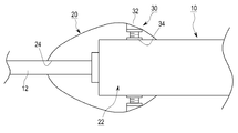
도 1 및 도 2에 도시된 바와 같이, 본 고안의 제1 실시 예에 따른 전선포설용 캡은 선박의 트레이에 포설되는 케이블(10) 선단을 보호 또는 견인하기 위한 캡으로서, 상기 케이블(10) 선단을 수용하는 케이블 수용부(22), 케이블(10)을 고정하기 위한 고정홈(26)과 케이블(10)을 견인하는 견인로프(12)가 삽입되는 로프 수용부(24)를 구비하는 본체(20), 상기 본체(20)의 케이블 수용부(22)에 삽입되는 케이블(10)을 면압으로 지지하기 위한 지지부(30)를 포함하여 구성된다.1 and 2, a cable installation cap according to a first embodiment of the present invention is a cap for protecting or pulling the tip of a
상기 본체(20)는 작업장 내 구조물과 같은 장애물과 충돌하는 경우 케이블(10)의 선단에 전달되는 충격을 감소시키도록 구비된다. 본체(20)는 케이블 수용부(22)의 표면이 로프 수용부(24)의 표면보다 작은 구배를 가지는 구체형상으로 구비된다. 이처럼 본체(20)는 구체형상으로 형성되어 장애물과 부딪히는 경우 충격을 완화할 수 있다. 또 케이블 트레이의 가이드바 사이로 빠지는 것을 방지하며, 장애물과 접촉 시 충격력을 줄여 자체적으로 이를 우회하므로 충격을 효과적으로 감소시킬 수 있다.The
한편, 본체(20)는 저마찰계수를 가지는 수지재질로 제작되어 케이블의 선단을 보호한다. 예를 들어, 본체(20)는 플라스틱으로 제작될 수 있지만 이에 국한되는 것은 아니다. 즉, 일정이상의 탄성을 갖고, 마찰력을 최소로 할 수 있는 것이면 충분하다 할 수 있다.
On the other hand, the
이 제1 실시 예에서는 도 2에 도시된 바와 같이, 본체(20)에 지지부(30)가 장착되어 케이블(10)의 선단을 고정하게 한다.In this first embodiment, as shown in FIG. 2, a supporting
상기 케이블 수용부(22)의 직경은 삽입된 케이블(10) 직경과 거의 동일하게 형성된다. 따라서 본체(20)에 삽입되는 케이블(10)은 케이블 수용부(22)의 직경과 동일하여 억지 끼우므로 결합될 수 있다. 이처럼 결합방법이 억지 끼움으로 이루어짐에 따라 결합을 위한 구성을 단순하게 할 수 있으며, 케이블이 본체(20) 내부와 밀착되어 견인의 용이성을 돕는 효과가 있다. 그리고 견인을 위한 로프 수용부(24)는 케이블 수용부(22)의 중앙부분에 마련되어 견인로프(12)를 수용한다. 견인로프(12)는 로프 수용부(24) 보다 큰 매듭을 내부로 지어 고정된다.The diameter of the
한편, 본체(20) 내부에 고정된 케이블(10)선단과 견인로프(12)는 일정한 간격으로 이격된 상태에서 삽입 및 고정되도록 마련하여도 좋다. 즉, 케이블(10)과 견인로프(12)가 맞닿는 것을 방지해 서로 간에 맞닿음으로 발생하는 손상을 방지할 수 있다.
Meanwhile, the tip of the
상술한 바와 같이, 상기 본체(20)에는 케이블 수용부(22)의 내부로 삽입된 케이블(10) 선단을 고정하는 지지부(30)를 설치할 수 있도록 고정홈(26)이 마련된다. 고정홈(26)은 케이블 수용부(22)의 외주면에 본체(20)를 수직으로 관통하도록 다수개, 예를 들어 90도 간격으로 4개가 마련된다. 또 고정홈(26)은 단턱과 같이 계단형식으로 구비된다. 이는 구체의 형상인 본체(20)에 지지부(30)를 삽입과정에서 용이함을 더한다.As described above, the
한편, 지지부(30)는 고정볼트(32)와 고정너트(34)로 구비되며, 나선 결합체로서 분할 형성된다. 지지부(30)는 고정너트(34)를 구비하여 본체(20)의 고정홈(26)에 고정된다.On the other hand, the
이와 같은 고정볼트(32)는 상기 본체(20)에서 카운터 보어 형태로 돌출되지 않게 장착된다. 또한 이러한 고정볼트(32)는 체결이 용이하도록 6각 렌치 볼트를 적용할 수 있다.The
< 실시 예 2 >≪ Example 2 >
본 고안에 따른 케이블을 보호하는 견인용 캡의 제2 실시 예를 도 3에 따라 설명한다. A second embodiment of a traction cap for protecting cables according to the present invention will now be described with reference to Fig.
도 3은 본 고안에 따른 케이블을 보호하는 견인용 캡의 제2 실시 예를 나타내는 도면이다.3 is a view showing a second embodiment of a traction cap for protecting a cable according to the present invention.
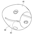
이 제2 실시 예는 도 3에 도시된 바와 같이, 본체(20)가 상부캡(41)과 하부캡(42)으로 분할되어, 절개부(43)를 형성하는 것이다. 즉, 제2 실시 예는 제1 실시 예와 달리 본체(20)의 사이로 절개부(43)를 구비하여 케이블(10)의 선단을 결합한다.3, the
따라서, 제2 실시 예의 경우, 제1 실시 예에 비해 다소 직경이 큰 케이블(10)을 용이하게 결합할 수 있도록 구비될 수 있다. 상부캡(41)과 하부캡(42)으로 분할된 본체(20)는 케이블 수용부(22)를 절개하는 형상의 절개부(43)을 형성한다.Therefore, in the case of the second embodiment, the
본체(20)가 수지재질로 제작되기 때문에 절개부(43)는 케이블(10)이 삽입되는 방향으로 벌려지는 것이 용이하다. 또 일정의 탄성력을 갖기 때문에 케이블(10)의 선단을 용이하게 고정할 수 있다는 효과가 있다. Since the
상기 제2 실시 예에서 지지부(30)와 본체(20)의 내부 구성은 제1 실시 예와 동일하므로, 반복적인 설명은 생략한다.
In the second embodiment, the inner structure of the
< 실시 예 3 >≪ Example 3 >
본 고안에 따른 케이블을 보호하는 견인용 캡의 제3 실시 예를 도 4에 따라 설명한다.A third embodiment of a traction cap for protecting a cable according to the present invention will be described with reference to Fig.
도 4는 본 고안에 따른 케이블을 보호하는 견인용 캡의 제3 실시 예를 나타내는 단면도이다.4 is a cross-sectional view showing a third embodiment of a traction cap for protecting a cable according to the present invention.
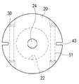
이 제3 실시 예는 도 4에 도시된 바와 같이, 절개부(43)가 형성된 본체(20)를 관통하는 관통구(51)와 관통구에 결합되는 볼트(52)를 마련하는 것이다. 즉, 제3 실시 예는 제1 실시 예 및 제2 실시 예와 달리 케이블(10)의 직경이 크거나, 작은 경우 모두 사용 가능하므로, 작업의 효율을 높일 수 있다는 효과가 있다.As shown in FIG. 4, the third embodiment is provided with a through
따라서, 케이블(10)의 직경이 케이블 수용부(22)보다 큰 경우 또는 작은 경우에도, 본체(20)를 관통한다. 또 관통구(51)에 결합되는 볼트(52)의 조임정도를 조절하는 것에 의해 케이블(10)을 확고하게 고정할 수가 있다.Therefore, even when the diameter of the
물론, 볼트(52)의 끝단을 고정하기 위한 수단으로 너트등을 구비할 수 있다.상기 제3 실시 예에서 케이블 수용부(22), 로프 수용부(24), 고정홈(26), 상부캡(41), 하부캡(42)의 구성은 제2 실시 예와 동일하므로, 반복적인 설명은 생략한다. In the third embodiment, the
이상 본 고안자에 의해서 이루어진 고안을 상기 실시 예에 따라 구체적으로 설명하였지만, 본 고안은 상기 실시 예에 한정되는 것은 아니고 그 요지를 이탈하지 않는 범위에서 여러 가지로 변경 가능한 것은 물론이다.Although the embodiments of the present invention have been described in detail with reference to the above embodiments, the present invention is not limited to the above embodiments, and various modifications may be made without departing from the scope of the present invention.
본 고안에 따른 케이블 보호 및 견인용 캡을 사용하는 것에 의해 케이블의 선단을 보호함과 동시에 이를 정확한 방향으로 견인할 수 있으므로 포설작업 능률을 향상시킬 수 있다.By using the cable protection and traction cap according to the present invention, it is possible to protect the tip of the cable and to pull it in the correct direction, so that the efficiency of the laying work can be improved.
10: 케이블
12: 견인로프
20: 본체
22:케이블 수용부
24: 로프 수용부
26: 고정홈
30: 지지부
32: 고정볼트
34: 고정너트
41: 상부캡
42: 하부캡
43: 절개부
51: 관통구
52: 볼트10: Cable 12: Traction rope
20: main body 22: cable receiving portion
24: rope accommodating portion 26: fixing groove
30: Support part 32: Fixing bolt
34: fixing nut 41: upper cap
42: lower cap 43:
51: through hole 52: bolt
Claims (6)
상기 케이블의 선단을 수용하는 케이블 수용부, 케이블을 고정하기 위한 다수의 고정홈과 케이블을 견인하는 견인로프가 삽입되는 로프 수용부를 구비하는 본체,
상기 본체의 케이블 수용부에 삽입되는 케이블을 상기 고정홈에서 면압으로 지지하기 위해 상기 고정홈에 장착되는 지지부를 포함하고,
상기 본체는 곡면으로 형성된 것을 특징으로 하는 전선포설용 캡.A cap for protecting or towing the tip of a cable installed on a ship,
A main body having a cable receiving portion for receiving the cable end, a plurality of fixing grooves for fixing the cable, and a rope accommodating portion for inserting a traction rope for pulling the cable,
And a support portion mounted in the fixing groove for supporting the cable inserted into the cable receiving portion of the main body by surface pressure in the fixing groove,
Wherein the body is formed as a curved surface.
상기 본체는 작업장 내 구조물과 충돌하는 경우 충격이 케이블의 선단에 전달되는 것을 감소시키도록 상기 케이블 수용부가 상기 로프 수용부 보다 작은 구배를 가지도록 형성되며, 미끄러짐이 원활하도록 저마찰계수를 가지는 수지재질로 제작된 것을 특징으로 하는 전선포설용 캡.The method according to claim 1,
The main body is formed to have a smaller gradient than the rope accommodating portion so as to reduce the transmission of the impact to the front end of the cable when colliding with the structure in the work area, and is made of a resin material having a low friction coefficient Wherein the cap is provided with a cap.
상기 로프 수용부는 상기 케이블 수용부의 중앙 부분에 마련된 것을 특징으로 하는 전선포설용 캡.3. The method of claim 2,
And the rope accommodating portion is provided at a central portion of the cable accommodating portion.
상기 지지부는 상기 본체에 대해 90도 간격으로 돌출되지 않게 장착되고 끝단에서 면압으로 상기 케이블을 지지하는 고정볼트를 구비하는 것을 특징으로 하는 전선포설용 캡.3. The method of claim 2,
Wherein the support portion includes a fixing bolt mounted to the main body so as not to protrude at an interval of 90 degrees and to support the cable with surface pressure at an end thereof.
상기 본체는 케이블 수용부의 공간보다 큰 직경의 케이블이 결합될 수 있도록 상부캡과 하부캡으로 분할된 것을 특징으로 하는 전선포설용 캡.The method according to claim 1,
Wherein the main body is divided into an upper cap and a lower cap so that a cable of a larger diameter than a space of the cable receiving portion can be coupled.
상기 본체에는 상기 상부캡과 하부캡을 관통하도록 형성된 관통구가 형성된 것을 특징으로 하는 전선포설용 캡.6. The method of claim 5,
And a through hole formed to penetrate the upper cap and the lower cap is formed in the main body.
Priority Applications (1)
| Application Number | Priority Date | Filing Date | Title |
|---|---|---|---|
| KR2020140000362U KR200489056Y1 (en) | 2014-01-16 | 2014-01-16 | Cap for cable installation |
Applications Claiming Priority (1)
| Application Number | Priority Date | Filing Date | Title |
|---|---|---|---|
| KR2020140000362U KR200489056Y1 (en) | 2014-01-16 | 2014-01-16 | Cap for cable installation |
Publications (2)
| Publication Number | Publication Date |
|---|---|
| KR20150002895U true KR20150002895U (en) | 2015-07-24 |
| KR200489056Y1 KR200489056Y1 (en) | 2019-04-24 |
Family
ID=53872629
Family Applications (1)
| Application Number | Title | Priority Date | Filing Date |
|---|---|---|---|
| KR2020140000362U KR200489056Y1 (en) | 2014-01-16 | 2014-01-16 | Cap for cable installation |
Country Status (1)
| Country | Link |
|---|---|
| KR (1) | KR200489056Y1 (en) |
Cited By (2)
| Publication number | Priority date | Publication date | Assignee | Title |
|---|---|---|---|---|
| KR102386459B1 (en) * | 2021-12-07 | 2022-04-14 | (주)일렉콤 | Cable automatic installation apparatus and cable installation method of construction using the same |
| CN114825202A (en) * | 2022-04-01 | 2022-07-29 | 华能国际电力江苏能源开发有限公司 | Shore power cable protection device |
Citations (6)
| Publication number | Priority date | Publication date | Assignee | Title |
|---|---|---|---|---|
| KR950010031Y1 (en) | 1993-11-09 | 1995-11-25 | 황성순 | End cap for electric cable |
| JPH09304671A (en) * | 1996-05-15 | 1997-11-28 | Fujikura Ltd | Traction terminal of optical cable |
| KR19990015731A (en) * | 1997-08-08 | 1999-03-05 | 이계철 | Traction device for laying optical cable |
| KR20000047116A (en) * | 1998-12-31 | 2000-07-25 | 강병호 | Optical cable pulling-eye |
| JP2009219224A (en) * | 2008-03-10 | 2009-09-24 | Yazaki Corp | Pulling eye for power cables |
| KR101013307B1 (en) | 2008-11-11 | 2011-02-09 | 조재현 | Protection cap fixing unit of ftth optical cable connector |
-
2014
- 2014-01-16 KR KR2020140000362U patent/KR200489056Y1/en active IP Right Grant
Patent Citations (6)
| Publication number | Priority date | Publication date | Assignee | Title |
|---|---|---|---|---|
| KR950010031Y1 (en) | 1993-11-09 | 1995-11-25 | 황성순 | End cap for electric cable |
| JPH09304671A (en) * | 1996-05-15 | 1997-11-28 | Fujikura Ltd | Traction terminal of optical cable |
| KR19990015731A (en) * | 1997-08-08 | 1999-03-05 | 이계철 | Traction device for laying optical cable |
| KR20000047116A (en) * | 1998-12-31 | 2000-07-25 | 강병호 | Optical cable pulling-eye |
| JP2009219224A (en) * | 2008-03-10 | 2009-09-24 | Yazaki Corp | Pulling eye for power cables |
| KR101013307B1 (en) | 2008-11-11 | 2011-02-09 | 조재현 | Protection cap fixing unit of ftth optical cable connector |
Cited By (3)
| Publication number | Priority date | Publication date | Assignee | Title |
|---|---|---|---|---|
| KR102386459B1 (en) * | 2021-12-07 | 2022-04-14 | (주)일렉콤 | Cable automatic installation apparatus and cable installation method of construction using the same |
| CN114825202A (en) * | 2022-04-01 | 2022-07-29 | 华能国际电力江苏能源开发有限公司 | Shore power cable protection device |
| CN114825202B (en) * | 2022-04-01 | 2024-01-26 | 华能国际电力江苏能源开发有限公司 | Shore power cable protection device |
Also Published As
| Publication number | Publication date |
|---|---|
| KR200489056Y1 (en) | 2019-04-24 |
Similar Documents
| Publication | Publication Date | Title |
|---|---|---|
| US9551438B2 (en) | Cable retaining apparatus | |
| US7246789B2 (en) | Cable clamping apparatus and method | |
| US20160141853A1 (en) | Ball grip compression fitting | |
| US9720198B2 (en) | Strain relief for armored cable | |
| US20130058615A1 (en) | Cable Carrier Device | |
| BR112019027620A2 (en) | fitting head assembly | |
| KR200489056Y1 (en) | Cap for cable installation | |
| US10926927B2 (en) | Cushion sleeve | |
| KR101280602B1 (en) | Anchor heads | |
| JP6335325B2 (en) | Edge protection bushing with integral clamp | |
| US20170110224A1 (en) | Cable fixator | |
| US20100276650A1 (en) | Tape or rope to pull a cable into a conduit | |
| JP2010231047A (en) | Traction end part for cable with connector | |
| RU2544987C2 (en) | Connector or connecting clamp for aerial cables with coating | |
| KR20140037503A (en) | Cable protect pipe for high tension wire of corruqated pipe type | |
| JP5150726B2 (en) | Optical fiber cable branching tool and optical fiber cable branching method | |
| US10807842B2 (en) | Wedge-style line clamp | |
| KR102023420B1 (en) | Hand Tool with Head Restraining Structure | |
| JP6829523B2 (en) | Wire-passing tool and cable laying method using the wire-passing tool | |
| JP6562206B2 (en) | Indirect sheet | |
| KR20160035919A (en) | Anchorage for ground anchor | |
| JP5602258B2 (en) | Bird damage prevention tool | |
| JP2020188621A (en) | Wire drawing jig, wire/cable, and wire drawing method for wire/cable | |
| EP3228880A1 (en) | Fir tree mount | |
| KR101166137B1 (en) | One-touch power cable hold grip |
Legal Events
| Date | Code | Title | Description |
|---|---|---|---|
| A201 | Request for examination | ||
| E902 | Notification of reason for refusal | ||
| E902 | Notification of reason for refusal | ||
| E701 | Decision to grant or registration of patent right | ||
| REGI | Registration of establishment |