KR20140146593A - Wireless equipment for transmitting uplink signal through reduced transmission resource block and power, and enodeb - Google Patents
Wireless equipment for transmitting uplink signal through reduced transmission resource block and power, and enodeb Download PDFInfo
- Publication number
- KR20140146593A KR20140146593A KR1020147027046A KR20147027046A KR20140146593A KR 20140146593 A KR20140146593 A KR 20140146593A KR 1020147027046 A KR1020147027046 A KR 1020147027046A KR 20147027046 A KR20147027046 A KR 20147027046A KR 20140146593 A KR20140146593 A KR 20140146593A
- Authority
- KR
- South Korea
- Prior art keywords
- predetermined
- mhz
- rbs
- channel bandwidth
- band
- Prior art date
Links
Images


Classifications
-
- H—ELECTRICITY
- H04—ELECTRIC COMMUNICATION TECHNIQUE
- H04L—TRANSMISSION OF DIGITAL INFORMATION, e.g. TELEGRAPHIC COMMUNICATION
- H04L5/00—Arrangements affording multiple use of the transmission path
- H04L5/0001—Arrangements for dividing the transmission path
- H04L5/0003—Two-dimensional division
- H04L5/0005—Time-frequency
- H04L5/0007—Time-frequency the frequencies being orthogonal, e.g. OFDM(A), DMT
- H04L5/001—Time-frequency the frequencies being orthogonal, e.g. OFDM(A), DMT the frequencies being arranged in component carriers
-
- H—ELECTRICITY
- H04—ELECTRIC COMMUNICATION TECHNIQUE
- H04L—TRANSMISSION OF DIGITAL INFORMATION, e.g. TELEGRAPHIC COMMUNICATION
- H04L5/00—Arrangements affording multiple use of the transmission path
- H04L5/003—Arrangements for allocating sub-channels of the transmission path
- H04L5/0044—Arrangements for allocating sub-channels of the transmission path allocation of payload
-
- H—ELECTRICITY
- H04—ELECTRIC COMMUNICATION TECHNIQUE
- H04W—WIRELESS COMMUNICATION NETWORKS
- H04W72/00—Local resource management
- H04W72/04—Wireless resource allocation
-
- H—ELECTRICITY
- H04—ELECTRIC COMMUNICATION TECHNIQUE
- H04W—WIRELESS COMMUNICATION NETWORKS
- H04W72/00—Local resource management
- H04W72/50—Allocation or scheduling criteria for wireless resources
- H04W72/54—Allocation or scheduling criteria for wireless resources based on quality criteria
-
- H—ELECTRICITY
- H04—ELECTRIC COMMUNICATION TECHNIQUE
- H04L—TRANSMISSION OF DIGITAL INFORMATION, e.g. TELEGRAPHIC COMMUNICATION
- H04L5/00—Arrangements affording multiple use of the transmission path
- H04L5/003—Arrangements for allocating sub-channels of the transmission path
- H04L5/0053—Allocation of signaling, i.e. of overhead other than pilot signals
-
- H—ELECTRICITY
- H04—ELECTRIC COMMUNICATION TECHNIQUE
- H04L—TRANSMISSION OF DIGITAL INFORMATION, e.g. TELEGRAPHIC COMMUNICATION
- H04L5/00—Arrangements affording multiple use of the transmission path
- H04L5/003—Arrangements for allocating sub-channels of the transmission path
- H04L5/0058—Allocation criteria
- H04L5/0066—Requirements on out-of-channel emissions
-
- H—ELECTRICITY
- H04—ELECTRIC COMMUNICATION TECHNIQUE
- H04W—WIRELESS COMMUNICATION NETWORKS
- H04W24/00—Supervisory, monitoring or testing arrangements
-
- H—ELECTRICITY
- H04—ELECTRIC COMMUNICATION TECHNIQUE
- H04W—WIRELESS COMMUNICATION NETWORKS
- H04W72/00—Local resource management
-
- H—ELECTRICITY
- H04—ELECTRIC COMMUNICATION TECHNIQUE
- H04W—WIRELESS COMMUNICATION NETWORKS
- H04W88/00—Devices specially adapted for wireless communication networks, e.g. terminals, base stations or access point devices
- H04W88/02—Terminal devices
-
- H—ELECTRICITY
- H04—ELECTRIC COMMUNICATION TECHNIQUE
- H04W—WIRELESS COMMUNICATION NETWORKS
- H04W88/00—Devices specially adapted for wireless communication networks, e.g. terminals, base stations or access point devices
- H04W88/08—Access point devices
-
- H—ELECTRICITY
- H04—ELECTRIC COMMUNICATION TECHNIQUE
- H04L—TRANSMISSION OF DIGITAL INFORMATION, e.g. TELEGRAPHIC COMMUNICATION
- H04L5/00—Arrangements affording multiple use of the transmission path
- H04L5/0001—Arrangements for dividing the transmission path
- H04L5/0003—Two-dimensional division
- H04L5/0005—Time-frequency
- H04L5/0007—Time-frequency the frequencies being orthogonal, e.g. OFDM(A), DMT
-
- H—ELECTRICITY
- H04—ELECTRIC COMMUNICATION TECHNIQUE
- H04L—TRANSMISSION OF DIGITAL INFORMATION, e.g. TELEGRAPHIC COMMUNICATION
- H04L5/00—Arrangements affording multiple use of the transmission path
- H04L5/0091—Signaling for the administration of the divided path
- H04L5/0096—Indication of changes in allocation
- H04L5/0098—Signalling of the activation or deactivation of component carriers, subcarriers or frequency bands
Abstract
본 발명의 일 개시는 무선 통신 시스템에서 상향링크 시그널을 감소된 전송 리소스 블록으로 전송하는 무선 기기를 제공한다. 상기 무선 기기는 프로세서와; E-UTRA 대역을 지원하되, 상기 프로세서의 제어에 따라 상향링크 시그널을 전송하는 RF(Radio Frequency) 부를 포함할 수 있다. 상기 RF부가 미리 정해진 채널 대역폭 및 미리 정해진 주파수 범위로 설정되고, 그리고 다른 주파수 범위를 보호하기 위해 미리 정해진 스퓨리어스 방사의 최대 허용치를 충족시켜야 할 경우, 상기 미리 정해진 채널 대역폭을 위한 전체 개수의 리소스 블록(RB)들 대신에, 미리 정해진 최대 개수의 리소스 블록(RB)들에 따라, 상기 상향링크 시그널이 전송될 수 있다.One disclosure of the present invention provides a wireless device for transmitting an uplink signal in a reduced transmission resource block in a wireless communication system. The wireless device comprising: a processor; And an RF (Radio Frequency) unit for supporting the E-UTRA band, and transmitting an uplink signal under the control of the processor. Wherein the RF unit is set to a predetermined channel bandwidth and a predetermined frequency range and if a maximum allowable value of a predetermined spurious emission is to be met to protect the other frequency range a total number of resource blocks for the predetermined channel bandwidth RB), the uplink signal may be transmitted according to a predetermined maximum number of resource blocks (RBs).
Description
본 발명은 전송 리소스 블록 제한 및 전력 감소에 관한 것이다.The present invention relates to transmission resource block limitation and power reduction.
UMTS(Universal Mobile Telecommunications System)의 향상인 3GPP(3rd Generation Partnership Project) LTE(long term evolution)는 3GPP 릴리이즈(release) 8로 소개되고 있다.The 3rd Generation Partnership Project (3GPP) long term evolution (LTE), an enhancement of Universal Mobile Telecommunications System (UMTS), is introduced as
3GPP LTE는 하향링크에서 OFDMA(orthogonal frequency division multiple access)를 사용하고, 상향링크에서 SC-FDMA(Single Carrier-frequency division multiple access)를 사용한다. OFDMA 이해하기 위해서는 OFDM을 알아야 한다. OFDM은 낮은 복잡도로 심볼간 간섭(inter-symbol interference) 효과를 감쇄시킬 수 있어, 사용되고 있다. OFDM은 직렬로 입력되는 데이터를 N개의 병렬 데이터로 변환하여, N개의 직교 부반송파(subcarrier)에 실어 전송한다. 부반송파는 주파수 차원에서 직교성을 유지한다. 한편, OFDMA은 OFDM을 변조 방식으로 사용하는 시스템에 있어서 이용 가능한 부반송파의 일부를 각 사용자에게 독립적으로 제공하여 다중 접속을 실현하는 다중 접속 방법을 말한다.3GPP LTE uses orthogonal frequency division multiple access (OFDMA) in the downlink and single carrier-frequency division multiple access (SC-FDMA) in the uplink. To understand OFDMA, we need to know OFDM. OFDM is used because it can attenuate the inter-symbol interference effect with low complexity. OFDM converts serial input data into N pieces of parallel data, and transmits the data on N orthogonal subcarriers. The subcarriers maintain orthogonality at the frequency dimension. On the other hand, OFDMA refers to a multiple access method in which a part of sub-carriers available in a system using OFDM as a modulation scheme is independently provided to each user to realize multiple access.
도 1은 3GPP LTE 무선 통신 시스템을 나타낸다.1 shows a 3GPP LTE wireless communication system.
도 1을 참조하면, LTE 무선 통신 시스템(10)는 적어도 하나의 기지국 Base Station, BS)(LTE에서는 eNodeB라고 함)(11)과 단말(12)을 포함한다.Referring to FIG. 1, the LTE
각 기지국(11)은 특정한 지리적 영역(15a, 15b, 15c)에 대해 통신 서비스를 제공한다. 이때, 기지국에서 단말로의 통신을 하향링크(downlink, DL)라 하며 단말에서 기지국으로의 통신을 상향링크(uplink, UL)라 한다.Each
만약, 각 지리적 영역(15a, 15b, 15c)에 여러 서비스 사업자에 의한 기지국들이 존재하는 경우, 서로 간섭을 일으킬 수 있다.If there are base stations by various service providers in the respective
이러한 간섭을 배제하기 위해, 각 서비스 사업자는 서로 다른 주파수 대역으로 서비스를 제공할 수 도 있다.To avoid such interference, each service provider may provide services in different frequency bands.
그러나, 각 서비스 사업자의 주파수 대역이 서로 인접한 경우에는, 여전히 간섭 문제가 남게 된다. 이러한 간섭 문제는 전송 전력을 줄이거나 전송 리소스 블록(Resource Block-RB)의 양을 제한하여 인접한 대역간 실질적인 주파수 간격을 늘임으로써, 해결될 수 있다. 그러나, 전송 전력을 단순히 줄이거나 전송 리소스 블록을 제한하게 되면, 서비스 커버리지도 줄어들게 되므로, 간섭 문제를 야기하지 않고, 적정한 수준으로 전송 전력 혹은 전송 리소스 블록을 줄이는 방안이 필요하다.However, when the frequency bands of the respective service providers are adjacent to each other, the interference problem still remains. This interference problem can be solved by reducing the transmit power or by limiting the amount of the resource block (RB) to increase the actual frequency interval between adjacent bands. However, simply reducing the transmission power or limiting the transmission resource block also reduces the service coverage, so there is a need to reduce the transmission power or transmission resource block to an appropriate level without causing interference problems.
따라서, 본 명세서의 일 개시는 전송 리소스 블록(RB)을 제한하여 전송 전력을 줄임으로써 인접 대역으로 누설되는 스퓨리어스 방사를 줄일 수 있는 방안을 제공하는 것을 목적으로 한다.Accordingly, one disclosure of the present disclosure is directed to providing a way to reduce spurious emissions that are leaked to adjacent bands by limiting transmission resource blocks (RBs) to reduce transmission power.
전술한 목적을 달성하기 위해서, 본 발명의 일 개시는 무선 통신 시스템에서 상향링크 시그널을 전송 블록을 제한하여 감소된 인접대역 스퓨리어스 방사로 전송하는 무선 기기를 제공한다. 상기 무선 기기는 프로세서와; E-UTRA 대역을 지원하되, 상기 프로세서의 제어에 따라 상향링크 시그널을 전송하는 RF(Radio Frequency) 부를 포함할 수 있다. 상기 RF부가 미리 정해진 채널 대역폭 및 미리 정해진 주파수 범위로 설정되고, 그리고 다른 주파수 범위를 보호하기 위해 미리 정해진 스퓨리어스 방사의 최대 허용치를 충족시켜야 할 경우, 상기 미리 정해진 채널 대역폭을 위한 전체 개수의 리소스 블록(RB)들 대신에, 미리 정해진 최대 개수의 리소스 블록(RB)들에 따라, 상기 상향링크 시그널이 전송될 수 있다.In order to accomplish the above object, one disclosure of the present invention provides a wireless device for transmitting an uplink signal in a wireless communication system by limiting the transmission block to a reduced adjacent band spurious domain emission. The wireless device comprising: a processor; And an RF (Radio Frequency) unit for supporting the E-UTRA band, and transmitting an uplink signal under the control of the processor. Wherein the RF unit is set to a predetermined channel bandwidth and a predetermined frequency range and if a maximum allowable value of a predetermined spurious emission is to be met to protect the other frequency range a total number of resource blocks for the predetermined channel bandwidth RB), the uplink signal may be transmitted according to a predetermined maximum number of resource blocks (RBs).
전술한 목적을 달성하기 위해서, 본 발명의 일 개시는 무선 통신 시스템에서 상향링크 시그널을 제한된 전송 리소스 블록으로 수신하는 기지국을 제공한다. 상기 기지국은 E-UTRA 대역을 지원하고, 무선 신호를 송신 및 수신하는 RF(Radio Frequency) 부와; 상기 RF부와 연결되어 제어하는 프로세서를 포함할 수 있다. 여기서, 상기 프로세서는 상기 RF부가 미리 정해진 채널 대역폭 및 미리 정해진 주파수 범위로 설정되고 , 그리고 다른 주파수 범위를 보호하기 위해 미리 정해진 스퓨리어스 방사의 최대 허용치를 충족시켜야 할 경우, 미리 정해진 채널 대역폭을 위한 전체 개수의 리소스 블록(RB)들 대신에, 미리 정해진 최대 개수의 리소스 블록(RB)들에 따라 상향링크 자원을 할당할 수 있다.In order to achieve the above object, one disclosure of the present invention provides a base station for receiving an uplink signal in a limited transmission resource block in a wireless communication system. The base station includes an RF (Radio Frequency) unit for supporting the E-UTRA band and transmitting and receiving a radio signal; And a processor connected to and controlling the RF unit. Herein, the processor is configured such that when the RF unit is set to a predetermined channel bandwidth and a predetermined frequency range, and the maximum allowable value of the predetermined spurious radiation is to be met to protect the other frequency range, the total number of channels for the predetermined channel bandwidth The uplink resources can be allocated according to a predetermined maximum number of resource blocks (RBs) instead of the resource blocks (RBs).
상기 미리 정해진 개수는 미리 정해진 스퓨리어스 방사 허용치를 충족하기 위해, 상기 미리 정해진 채널 대역폭을 위한 전체 개수의 RB들 중에서 일부 개수의 리소스 블록(RB)을 감소시킴으로써 구해질 수 있다. 상기 미리 정해진 스퓨리어스 방사 허용치는 -40dBm/MHz일 수 있다.The predetermined number may be obtained by reducing some of the number of resource blocks (RBs) among the total number of RBs for the predetermined channel bandwidth to meet a predetermined spurious emission tolerance. The predetermined spurious emission tolerance may be -40 dBm / MHz.
상기 미리 정해진 채널 대역폭이 5MHz인 경우, 상기 RB의 전체 개수는 25일 수 있고, 상기 미리 정해진 채널 대역폭이 10 MHz인 경우, 상기 RB의 전체 개수는 50일 수 있다.If the predetermined channel bandwidth is 5 MHz, the total number of RBs may be 25, and if the predetermined channel bandwidth is 10 MHz, the total number of RBs may be 50.
상기 미리 정해진 채널 대역폭이 5 MHz인 경우, 상기 미리 정해진 RB들의 개수는 상기 전체 RB의 개수인 25 개에서 제한해야 할 5개를 감소시킴으로써 구해진 20개보다 작거나 같을 수 있고, 상기 미리 정해진 채널 대역폭이 10 MHz인 경우, 상기 미리 정해진 RB들의 개수는 상기 전체 RB의 개수인 50개에서 제한해야 할 18개를 감소시킴으로써 구해진 32개 보다 작거나 같을 수 있다.If the predetermined channel bandwidth is 5 MHz, the number of the predetermined RBs may be less than or equal to 20, which is obtained by decreasing the number of 5 to be limited to 25 from the total number of RBs, and the predetermined channel bandwidth Is 10 MHz, the number of the predetermined RBs may be less than or equal to 32, which is obtained by decreasing the number of RBs to be limited to 50 from the total number of RBs.
상기 미리 정해진 채널 대역폭이 5MHz인 경우, 상기 미리 정해진 RB들의 개수는 20보다 작거나 같을 수 있고, 상기 미리 정해진 채널 대역폭이 10 MHz인 경우, 상기 미리 정해진 RB들의 개수는 32보다 작거나 같을 수 있다.If the predetermined channel bandwidth is 5 MHz, the number of predetermined RBs may be less than or equal to 20, and if the predetermined channel bandwidth is 10 MHz, the predetermined number of RBs may be less than or equal to 32 .
상기 미리 정해진 주파수 범위는 3GPP LTE에서 정의되는 대역 8일 수 있다.The predetermined frequency range may be
상기 대역8에 따르면, 상기 미리 정해진 주파수 범위는 상향링크에 대해서 880MHz~915 MHz이고, 하향링크에 대해서 925 MHz~960 MHz일 수 있다.According to the
상기 미리 정해진 RB의 개수가 Nrestricted _ RB 로 표현되는 경우, Nrestricted _ RB =Nfull RB of transmission bandwidth-NRB _ limitation에 의해서 산출되고, 여기서, Nfull RB of transmission bandwidth은 채널 대역폭을 구성하는 전송 대역폭의 전체 RB개수이고, NRB _ limitation는 미리 정해진 스퓨리어스 방사 허용치를 충족시키기 위해 제한될 RB의 개수 일 수 있다.When the number of the predetermined RB represented by the restricted _ N RB, RB = N N _ restricted full RB of transmission bandwidth -N RB _ limitation , where N full RB of transmission bandwidth is the total number of RB transmission bandwidth that make up the channel bandwidth, N RB _ limitation may be the number of RB to be limited in order to meet the predetermined spurious emission limit.
본 명세서의 개시에 의하면, 제한된 전송 리소스 블록만큼 제외한 전송리소스 블록으로 상향링크를 송신함으로써 인접 대역 스퓨리어스 방사를 줄일 수 있으므로, 인접한 채널로의 간섭을 줄일 수 있다.According to the disclosure of the present specification, it is possible to reduce adjacent band spurious radiated emissions by transmitting an uplink to a transmission resource block excluding a limited transmission resource block, thereby reducing interference to adjacent channels.
..
도 1은 3GPP LTE 무선 통신 시스템을 나타낸다.
도 2는 3GPP LTE에서 무선 프레임(radio frame)의 구조를 나타낸다.
도 3은 3GPP LTE에서 하나의 상향링크 슬롯에 대한 자원 그리드(resource grid)를 나타낸 예시도이다.
도 4는 하향링크 서브프레임의 구조를 나타낸다.
도 5는 3GPP LTE에서 UL 서브프레임의 구조를 나타낸다.
도 6은 기존의 단일 반송파 시스템과 반송파 집성 시스템의 비교 예이다.
도 7은 반송파 집성 시스템에서 교차 반송파 스케줄링을 예시한다.
도 8은 반송파 집성 시스템에서 교차 반송파 스케줄링이 설정된 경우 스케줄링 예를 나타낸다.
도 9은 3GPP LTE에서 채택된 상향링크 액세스 방식인 SC-FDMA 전송 방식을 설명하기 위한 블록도이다.
도 10은 클러스터된 DFT-s OFDM 전송 방식을 적용한 전송기의 일 예이다.
도 11은 LTE 시스템에서 어느 사업자가 다른 사업자의 대역과 인접한 대역을사용할 때 간섭이 발생하는 예를 나타낸다.
도 12은 불요 방사(unwanted emission)의 개념을 나타낸다.
도 13은 도 12에 도시된 불요 방사 중 외부 대역에서의 방사를 구체적으로 나타낸다.
도 14은 도 12에 도시된 채널 대역(MHz)와 리소스 블록(RB)의 관계를 나타낸다.
도 15는 전송 리소스 블록 제한을 위한 예시적인 첫 번째 실험 결과를 나타낸다.
도 16은 도 15의 실험 결과를 다른 형태로 나타낸다.
도 17은 전송 리소스 블록 제한을 위한 예시적인 두 번째 실험 결과를 나타낸다.
도 18은 도 17의 실험 결과를 다른 형태로 나타낸다.
도 19는 시스템 정보를 전달하는 과정을 나타낸다.
도 20은 단말이 상향링크 데이터를 전송하는 과정을 나타낸다.
도 21은 본 발명의 실시예가 구현되는 무선통신 시스템을 나타낸 블록도이다.1 shows a 3GPP LTE wireless communication system.
2 shows a structure of a radio frame in 3GPP LTE.
3 is an exemplary diagram illustrating a resource grid for one uplink slot in 3GPP LTE.
4 shows a structure of a downlink sub-frame.
5 shows the structure of UL subframe in 3GPP LTE.
6 is a comparative example of a conventional single carrier system and a carrier aggregation system.
7 illustrates cross-carrier scheduling in a carrier aggregation system.
8 shows an example of scheduling when cross carrier scheduling is set in the carrier aggregation system.
FIG. 9 is a block diagram illustrating an SC-FDMA transmission scheme, which is an uplink access scheme adopted in 3GPP LTE.
10 is an example of a transmitter applying the clustered DFT-s OFDM transmission scheme.
11 shows an example in which interference occurs when a carrier uses a band adjacent to another carrier in the LTE system.
Figure 12 shows the concept of unwanted emission.
FIG. 13 specifically shows the emission in the outer band of the unwanted radiation shown in FIG.
FIG. 14 shows the relationship between the channel band (MHz) and the resource block (RB) shown in FIG.
15 shows an exemplary first experimental result for transmission resource block limitation.
Fig. 16 shows the experimental result of Fig. 15 in a different form.
Figure 17 shows an exemplary second experimental result for transmission resource block limitation.
Fig. 18 shows the experimental result of Fig. 17 in a different form.
19 shows a process of transmitting system information.
20 shows a process in which a UE transmits uplink data.
21 is a block diagram illustrating a wireless communication system in which an embodiment of the present invention is implemented.
본 명세서에서 사용되는 기술적 용어는 단지 특정한 실시 예를 설명하기 위해 사용된 것으로, 본 발명을 한정하려는 의도가 아님을 유의해야 한다. 또한, 본 명세서에서 사용되는 기술적 용어는 본 명세서에서 특별히 다른 의미로 정의되지 않는 한, 본 발명이 속하는 기술 분야에서 통상의 지식을 가진 자에 의해 일반적으로 이해되는 의미로 해석되어야 하며, 과도하게 포괄적인 의미로 해석되거나, 과도하게 축소된 의미로 해석되지 않아야 한다. 또한, 본 명세서에서 사용되는 기술적인 용어가 본 발명의 사상을 정확하게 표현하지 못하는 잘못된 기술적 용어일 때에는, 당업자가 올바르게 이해할 수 있는 기술적 용어로 대체되어 이해되어야 할 것이다. 또한, 본 발명에서 사용되는 일반적인 용어는 사전에 정의되어 있는 바에 따라, 또는 전후 문맥상에 따라 해석되어야 하며, 과도하게 축소된 의미로 해석되지 않아야 한다.It is noted that the technical terms used herein are used only to describe specific embodiments and are not intended to limit the invention. It is also to be understood that the technical terms used herein are to be interpreted in a sense generally understood by a person skilled in the art to which the present invention belongs, Should not be construed to mean, or be interpreted in an excessively reduced sense. Further, when a technical term used herein is an erroneous technical term that does not accurately express the spirit of the present invention, it should be understood that technical terms that can be understood by a person skilled in the art are replaced. In addition, the general terms used in the present invention should be interpreted according to a predefined or prior context, and should not be construed as being excessively reduced.
또한, 본 명세서에서 사용되는 단수의 표현은 문맥상 명백하게 다르게 뜻하지 않는 한, 복수의 표현을 포함한다. 본 출원에서, "구성된다" 또는 "포함한다" 등의 용어는 명세서 상에 기재된 여러 구성 요소들, 또는 여러 단계들을 반드시 모두 포함하는 것으로 해석되지 않아야 하며, 그 중 일부 구성 요소들 또는 일부 단계들은 포함되지 않을 수도 있고, 또는 추가적인 구성 요소 또는 단계들을 더 포함할 수 있는 것으로 해석되어야 한다.Also, the singular forms "as used herein include plural referents unless the context clearly dictates otherwise. In the present application, the term "comprising" or "comprising" or the like should not be construed as necessarily including the various elements or steps described in the specification, Or may be further comprised of additional components or steps.
또한, 본 명세서에서 사용되는 제1, 제2 등과 같이 서수를 포함하는 용어는 다양한 구성 요소들을 설명하는데 사용될 수 있지만, 상기 구성 요소들은 상기 용어들에 의해 한정되어서는 안 된다. 상기 용어들은 하나의 구성요소를 다른 구성요소로부터 구별하는 목적으로만 사용된다. 예를 들어, 본 발명의 권리 범위를 벗어나지 않으면서 제1 구성요소는 제2 구성 요소로 명명될 수 있고, 유사하게 제2 구성 요소도 제1 구성 요소로 명명될 수 있다.Furthermore, terms including ordinals such as first, second, etc. used in this specification can be used to describe various elements, but the elements should not be limited by the terms. The terms are used only for the purpose of distinguishing one component from another. For example, without departing from the scope of the present invention, the first component may be referred to as a second component, and similarly, the second component may also be referred to as a first component.
어떤 구성요소가 다른 구성요소에 "연결되어" 있다거나 "접속되어" 있다고 언급된 때에는, 그 다른 구성요소에 직접적으로 연결되어 있거나 또는 접속되어 있을 수도 있지만, 중간에 다른 구성요소가 존재할 수도 있다. 반면에, 어떤 구성요소가 다른 구성요소에 "직접 연결되어" 있다거나 "직접 접속되어" 있다고 언급된 때에는, 중간에 다른 구성요소가 존재하지 않는 것으로 이해되어야 할 것이다.When an element is referred to as being "connected" or "connected" to another element, it may be directly connected or connected to the other element, but other elements may be present in between. On the other hand, when an element is referred to as being "directly connected" or "directly connected" to another element, it should be understood that there are no other elements in between.
이하, 첨부된 도면을 참조하여 본 발명에 따른 바람직한 실시예를 상세히 설명하되, 도면 부호에 관계없이 동일하거나 유사한 구성 요소는 동일한 참조 번호를 부여하고 이에 대한 중복되는 설명은 생략하기로 한다. 또한, 본 발명을 설명함에 있어서 관련된 공지 기술에 대한 구체적인 설명이 본 발명의 요지를 흐릴 수 있다고 판단되는 경우 그 상세한 설명을 생략한다. 또한, 첨부된 도면은 본 발명의 사상을 쉽게 이해할 수 있도록 하기 위한 것일뿐, 첨부된 도면에 의해 본 발명의 사상이 제한되는 것으로 해석되어서는 아니됨을 유의해야 한다. 본 발명의 사상은 첨부된 도면외에 모든 변경, 균등물 내지 대체물에 까지도 확장되는 것으로 해석되어야 한다.Hereinafter, exemplary embodiments of the present invention will be described in detail with reference to the accompanying drawings, wherein like reference numerals refer to like or similar elements throughout the several views, and redundant description thereof will be omitted. In the following description, well-known functions or constructions are not described in detail since they would obscure the invention in unnecessary detail. It is to be noted that the accompanying drawings are only for the understanding of the present invention and should not be construed as limiting the scope of the present invention. The spirit of the present invention should be construed as extending to all modifications, equivalents, and alternatives in addition to the appended drawings.
이하, 사용되는 무선기기는 고정되거나 이동성을 가질 수 있으며, 단말(Terminal), MT(mobile terminal), UE(User Equipment), ME(Mobile Equipment), MS(mobile station), UT(user terminal), SS(subscriber station), 휴대기기(Handheld Device), AT(Access Terminal)등 다른 용어로 불릴 수 있다.Hereinafter, the wireless device to be used may be fixed or mobile and may be a terminal, a mobile terminal, a user equipment (ME), a mobile equipment (ME), a mobile station (MS) Such as a subscriber station (SS), a handheld device, or an access terminal (AT).
그리고 이하에서 사용되는 기지국이라는 용어는 일반적으로 무선기기와 통신하는 고정된 지점(fixed station)을 말하며, eNB(evolved-NodeB), BTS(Base Transceiver System), 액세스 포인트(Access Point) 등 다른 용어로 불릴 수 있다.The term base station as used herein refers to a fixed station that communicates with a wireless device in general and may be referred to as an evolved-NodeB (eNB), a base transceiver system (BTS), an access point Can be called.
이하에서는 3GPP(3rd Generation Partnership Project) 3GPP LTE(long term evolution) 또는 3GPP LTE-A(LTE-Advanced)를 기반으로 본 발명이 적용되는 것을 기술한다. 이는 예시에 불과하고, 본 발명은 다양한 무선 통신 시스템에 적용될 수 있다. 이하에서, LTE라 함은 LTE 및/또는 LTE-A를 포함한다.Hereinafter, it is described that the present invention is applied based on 3rd Generation Partnership Project (3GPP) 3GPP long term evolution (LTE) or 3GPP LTE-A (LTE-Advanced). This is merely an example, and the present invention can be applied to various wireless communication systems. Hereinafter, LTE includes LTE and / or LTE-A.
한편, 3GPP 에서 정의하는 LTE 시스템은 이와 같은 MIMO를 채택하였다. 이하에서는, LTE 시스템에 대해서 보다 상세하게 알아보기로 한다.On the other hand, LTE system defined by 3GPP adopts such MIMO. Hereinafter, the LTE system will be described in more detail.
도 2는 3GPP LTE에서 무선 프레임(radio frame)의 구조를 나타낸다.2 shows a structure of a radio frame in 3GPP LTE.
도 2를 참조하면, 무선 프레임은 10개의 서브프레임(subframe)으로 구성되고, 하나의 서브프레임은 2개의 슬롯(slot)으로 구성된다. 무선 프레임 내 슬롯은 0부터 19까지 슬롯 번호가 매겨진다. 하나의 서브프레임이 전송되는 데 걸리는 시간을 TTI(transmission time interval)라 한다. TTI는 데이터 전송을 위한 스케줄링 단위라 할 수 있다. 예를 들어, 하나의 무선 프레임의 길이는 10ms이고, 하나의 서브프레임의 길이는 1ms이고, 하나의 슬롯의 길이는 0.5ms 일 수 있다.Referring to FIG. 2, a radio frame is composed of 10 subframes, and one subframe is composed of two slots. The slots in the radio frame are slot numbered from 0 to 19. The time taken for one subframe to be transmitted is called a transmission time interval (TTI). TTI is a scheduling unit for data transmission. For example, the length of one radio frame is 10 ms, the length of one subframe is 1 ms, and the length of one slot may be 0.5 ms.
무선 프레임의 구조는 예시에 불과하고, 무선 프레임에 포함되는 서브프레임의 수 또는 서브프레임에 포함되는 슬롯의 수 등은 다양하게 변경될 수 있다.The structure of the radio frame is merely an example, and the number of subframes included in the radio frame, the number of slots included in the subframe, and the like can be variously changed.
도 3은 3GPP LTE에서 하나의 상향링크 슬롯에 대한 자원 그리드(resource grid)를 나타낸 예시도이다.3 is an exemplary diagram illustrating a resource grid for one uplink slot in 3GPP LTE.
도 3을 참조하면, 상향링크 슬롯은 시간 영역(time domain)에서 복수의 OFDM(orthogonal frequency division multiplexing) 심벌을 포함하고, 주파수 영역(frequency domain)에서 NUL 자원블록(Resource Block, RB)을 포함한다. OFDM 심벌은 하나의 심벌 구간(symbol period)을 표현하기 위한 것으로, 시스템에 따라 SC-FDMA 심벌, OFDMA 심벌 또는 심벌 구간이라고 할 수 있다. 자원블록은 자원 할당 단위로 주파수 영역에서 복수의 부반송파를 포함한다. 상향링크 슬롯에 포함되는 자원블록의 수 NUL 은 셀에서 설정되는 상향링크 전송 대역폭(bandwidth)에 종속한다. 자원 그리드 상의 각 요소(element)를 자원요소(resource element)라 한다.3, an uplink slot includes a plurality of orthogonal frequency division multiplexing (OFDM) symbols in a time domain and a NUL resource block (RB) in a frequency domain . An OFDM symbol represents one symbol period and may be referred to as an SC-FDMA symbol, an OFDMA symbol, or a symbol interval depending on the system. The resource block includes a plurality of subcarriers in the frequency domain as a resource allocation unit. The number NUL of resource blocks included in the uplink slot is dependent on the uplink transmission bandwidth set in the cell. Each element on the resource grid is called a resource element.
여기서, 하나의 자원블록은 시간 영역에서 7 OFDM 심벌, 주파수 영역에서 12 부반송파로 구성되는 7×12 자원요소를 포함하는 것을 예시적으로 기술하나, 자원블록 내 부반송파의 수와 OFDM 심벌의 수는 이에 제한되는 것은 아니다. 자원블록이 포함하는 OFDM 심벌의 수 또는 부반송파의 수는 다양하게 변경될 수 있다. OFDM 심벌의 수는 사이클릭 프리픽스(Cyclic Prefix, 이하 CP)의 길이에 따라 변경될 수 있다. 예를 들어, 노멀(normal) CP의 경우 OFDM 심벌의 수는 7이고, 확장된(extended) CP의 경우 OFDM 심벌의 수는 6이다.Here, one resource block exemplarily includes 7 × 12 resource elements including 7 OFDM symbols in the time domain and 12 subcarriers in the frequency domain, but the number of subcarriers and the number of OFDM symbols in the resource block are But is not limited to. The number of OFDM symbols or the number of subcarriers included in the resource block may be variously changed. The number of OFDM symbols can be changed according to the length of a cyclic prefix (CP). For example, the number of OFDM symbols in a normal CP is 7, and the number of OFDM symbols is 6 in an extended CP.
도 3의 3GPP LTE에서 하나의 상향링크 슬롯에 대한 자원 그리드는 하향링크 슬롯에 대한 자원 그리드에도 적용될 수 있다.In 3GPP LTE of FIG. 3, a resource grid for one uplink slot can be applied to a resource grid for a downlink slot.
도 4는 하향링크 서브프레임의 구조를 나타낸다.4 shows a structure of a downlink sub-frame.
이는 3GPP TS 36.211 V10.4.0 (2011-12) "Evolved Universal Terrestrial Radio Access (E-UTRA); Physical Channels and Modulation (Release 10)"의 4절을 참조할 수 있다.This can be referred to
무선 프레임(radio frame)은 0~9의 인덱스가 매겨진 10개의 서브프레임을 포함한다. 하나의 서브프레임(subframe)은 2개의 연속적인 슬롯을 포함한다. 따라서, 무선 프레임은 20개의 슬롯을 포함한다. 하나의 서브 프레임이 전송되는데 걸리는 시간을 TTI(transmission time interval)이라 하고, 예를 들어 하나의 서브프레임의 길이는 1ms이고, 하나의 슬롯의 길이는 0.5ms 일 수 있다.A radio frame includes 10 subframes indexed from 0 to 9. One subframe includes two consecutive slots. Thus, the radio frame includes 20 slots. The time taken for one subframe to be transmitted is referred to as a transmission time interval (TTI). For example, the length of one subframe may be 1 ms and the length of one slot may be 0.5 ms.
하나의 슬롯은 시간 영역에서 복수의 OFDM(orthogonal frequency division multiplexing) 심벌을 포함할 수 있다. OFDM 심벌은 3GPP LTE가 하향링크(downlink, DL)에서 OFDMA(orthogonal frequency division multiple access)를 사용하므로, 시간 영역에서 하나의 심벌 구간(symbol period)을 표현하기 위한 것에 불과할 뿐, 다중 접속 방식이나 명칭에 제한을 두는 것은 아니다. 예를 들어, OFDM 심벌은 SC-FDMA(single carrier-frequency division multiple access) 심벌, 심벌 구간 등 다른 명칭으로 불릴 수 있다.One slot may comprise a plurality of orthogonal frequency division multiplexing (OFDM) symbols in the time domain. OFDM symbols are used to represent one symbol period in the time domain since 3GPP LTE uses orthogonal frequency division multiple access (OFDMA) in a downlink (DL) It is not limited. For example, an OFDM symbol may be referred to as another name such as a single carrier-frequency division multiple access (SC-FDMA) symbol, a symbol period, or the like.
하나의 슬롯은 7 OFDM 심벌을 포함하는 것을 예시적으로 기술하나, CP(Cyclic Prefix)의 길이에 따라 하나의 슬롯에 포함되는 OFDM 심벌의 수는 바뀔 수 있다. 3GPP TS 36.211 V10.4.0에 의하면, 노멀(normal) CP에서 1 슬롯은 7 OFDM 심벌을 포함하고, 확장(extended) CP에서 1 슬롯은 6 OFDM 심벌을 포함한다.One slot exemplarily includes seven OFDM symbols, but the number of OFDM symbols included in one slot may be changed according to the length of a CP (Cyclic Prefix). According to 3GPP TS 36.211 V10.4.0, one slot in a normal CP includes seven OFDM symbols, and one slot in an extended CP includes six OFDM symbols.
자원블록(resource block, RB)은 자원 할당 단위로, 하나의 슬롯에서 복수의 부반송파를 포함한다. 예를 들어, 하나의 슬롯이 시간 영역에서 7개의 OFDM 심벌을 포함하고, 자원블록은 주파수 영역에서 12개의 부반송파를 포함한다면, 하나의 자원블록은 7×12개의 자원요소(resource element, RE)를 포함할 수 있다.A resource block (RB) is a resource allocation unit and includes a plurality of subcarriers in one slot. For example, if one slot includes 7 OFDM symbols in the time domain and the resource block includes 12 subcarriers in the frequency domain, one resource block includes 7 × 12 resource elements (REs) .
DL(downlink) 서브프레임은 시간 영역에서 제어영역(control region)과 데이터영역(data region)으로 나누어진다. 제어영역은 서브프레임내의 첫번째 슬롯의 앞선 최대 3개의 OFDM 심벌을 포함하나, 제어영역에 포함되는 OFDM 심벌의 개수는 바뀔 수 있다. 제어영역에는 PDCCH(Physical Downlink Control Channel) 및 다른 제어채널이 할당되고, 데이터영역에는 PDSCH가 할당된다.A DL (downlink) subframe is divided into a control region and a data region in a time domain. The control region includes up to three OFDM symbols preceding the first slot in the subframe, but the number of OFDM symbols included in the control region may be changed. A Physical Downlink Control Channel (PDCCH) and another control channel are allocated to the control region, and a PDSCH is allocated to the data region.
3GPP TS 36.211 V10.4.0에 개시된 바와 같이, 3GPP LTE에서 물리채널은 데이터 채널인 PDSCH(Physical Downlink Shared Channel)와 PUSCH(Physical Uplink Shared Channel) 및 제어채널인 PDCCH(Physical Downlink Control Channel), PCFICH(Physical Control Format Indicator Channel), PHICH(Physical Hybrid-ARQ Indicator Channel) 및 PUCCH(Physical Uplink Control Channel)로 나눌 수 있다.As disclosed in 3GPP TS 36.211 V10.4.0, in 3GPP LTE, a physical channel includes a Physical Downlink Shared Channel (PDSCH), a Physical Uplink Shared Channel (PUSCH) and a Physical Downlink Control Channel (PDCCH) Control Format Indicator Channel), PHICH (Physical Hybrid-ARQ Indicator Channel), and PUCCH (Physical Uplink Control Channel).
서브프레임의 첫번째 OFDM 심벌에서 전송되는 PCFICH는 서브프레임내에서 제어채널들의 전송에 사용되는 OFDM 심벌의 수(즉, 제어영역의 크기)에 관한 CFI(control format indicator)를 나른다. 무선기기는 먼저 PCFICH 상으로 CFI를 수신한 후, PDCCH를 모니터링한다.The PCFICH transmitted in the first OFDM symbol of the subframe carries a control format indicator (CFI) regarding the number of OFDM symbols (i.e., the size of the control region) used for transmission of the control channels in the subframe. The wireless device first receives the CFI on the PCFICH and then monitors the PDCCH.
PDCCH와 달리, PCFICH는 블라인드 디코딩을 사용하지 않고, 서브프레임의 고정된 PCFICH 자원을 통해 전송된다.Unlike PDCCH, PCFICH does not use blind decoding, but is transmitted via fixed PCFICH resources in the subframe.
PHICH는 UL HARQ(hybrid automatic repeat request)를 위한 ACK(positive-acknowledgement)/NACK(negative-acknowledgement) 신호를 나른다. 무선기기에 의해 전송되는 PUSCH 상의 UL(uplink) 데이터에 대한 ACK/NACK 신호는 PHICH 상으로 전송된다.The PHICH carries an ACK (positive-acknowledgment) / NACK (negative-acknowledgment) signal for a hybrid automatic repeat request (UL HARQ). The ACK / NACK signal for UL (uplink) data on the PUSCH transmitted by the wireless device is transmitted on the PHICH.
PBCH(Physical Broadcast Channel)은 무선 프레임의 첫번째 서브프레임의 두번째 슬롯의 앞선 4개의 OFDM 심벌에서 전송된다. PBCH는 무선기기가 기지국과 통신하는데 필수적인 시스템 정보를 나르며, PBCH를 통해 전송되는 시스템 정보를 MIB(master information block)라 한다. 이와 비교하여, PDCCH에 의해 지시되는 PDSCH 상으로 전송되는 시스템 정보를 SIB(system information block)라 한다.The PBCH (Physical Broadcast Channel) is transmitted in four OFDM symbols preceding the second slot of the first subframe of the radio frame. The PBCH carries the system information necessary for the radio equipment to communicate with the base station, and the system information transmitted through the PBCH is called the master information block (MIB). In contrast, the system information transmitted on the PDSCH indicated by the PDCCH is called a system information block (SIB).
PDCCH를 통해 전송되는 제어정보를 하향링크 제어정보(downlink control information, DCI)라고 한다. DCI는 PDSCH의 자원 할당(이를 DL 그랜트(downlink grant)라고도 한다), PUSCH의 자원 할당(이를 UL 그랜트(uplink grant)라고도 한다), 임의의 UE 그룹내 개별 UE들에 대한 전송 파워 제어 명령의 집합 및/또는 VoIP(Voice over Internet Protocol)의 활성화를 포함할 수 있다.The control information transmitted through the PDCCH is referred to as downlink control information (DCI). The DCI includes a resource allocation (also referred to as a DL grant) of the PDSCH, a resource allocation (also referred to as an UL grant) of the PUSCH, a set of transmission power control commands for individual UEs in any UE group And / or Voice over Internet Protocol (VoIP).
3GPP LTE에서는 PDCCH의 검출을 위해 블라인드 디코딩을 사용한다. 블라인드 디코딩은 수신되는 PDCCH(이를 후보(candidate) PDCCH라 함)의 CRC(Cyclic Redundancy Check)에 원하는 식별자를 디마스킹하고, CRC 오류를 체크하여 해당 PDCCH가 자신의 제어채널인지 아닌지를 확인하는 방식이다. 기지국은 무선기기에게 보내려는 DCI에 따라 PDCCH 포맷을 결정한 후 DCI에 CRC를 붙이고, PDCCH의 소유자(owner)나 용도에 따라 고유한 식별자(이를 RNTI(Radio Network Temporary Identifier)라고 한다)를 CRC에 마스킹한다.In 3GPP LTE, blind decoding is used to detect PDCCH. The blind decoding demodulates a desired identifier in a CRC (Cyclic Redundancy Check) of a received PDCCH (referred to as a candidate PDCCH), checks a CRC error, and confirms whether the corresponding PDCCH is its own control channel . The base station determines the PDCCH format according to the DCI to be transmitted to the wireless device, attaches a CRC to the DCI, and masks a unique identifier (referred to as an RNTI (Radio Network Temporary Identifier)) to the CRC according to the owner or use of the PDCCH do.
3GPP TS 36.211 V10.4.0에 의하면, 상향링크 채널은 PUSCH, PUCCH, SRS(Sounding Reference Signal), PRACH(Physical Random Access Channel)을 포함한다.According to 3GPP TS 36.211 V10.4.0, the uplink channel includes a PUSCH, a PUCCH, a sounding reference signal (SRS), and a physical random access channel (PRACH).
도 5는 3GPP LTE에서 UL 서브프레임의 구조를 나타낸다.5 shows the structure of UL subframe in 3GPP LTE.
도 5를 참조하면, 상향링크 서브프레임은 주파수 영역에서 제어 영역과 데이터 영역으로 나뉠 수 있다. 제어 영역에는 상향링크 제어 정보가 전송되기 위한 PUCCH(Physical Uplink Control Channel)가 할당된다. 데이터 영역은 데이터(경우에 따라 제어 정보도 함께 전송될 수 있다)가 전송되기 위한 PUSCH(Physical Uplink Shared Channel)가 할당된다.Referring to FIG. 5, the uplink subframe may be divided into a control region and a data region in a frequency domain. A PUCCH (Physical Uplink Control Channel) for transmitting uplink control information is allocated to the control region. A data area is allocated a physical uplink shared channel (PUSCH) for transmitting data (in some cases, control information may be transmitted together).
하나의 단말에 대한 PUCCH는 서브프레임에서 자원블록 쌍(RB pair)으로 할당된다. 자원블록 쌍에 속하는 자원블록들은 제1 슬롯과 제2 슬롯 각각에서 서로 다른 부반송파를 차지한다. PUCCH에 할당되는 자원블록 쌍에 속하는 자원블록이 차지하는 주파수는 슬롯 경계(slot boundary)를 기준으로 변경된다. 이를 PUCCH에 할당되는 RB 쌍이 슬롯 경계에서 주파수가 홉핑(frequency-hopped)되었다고 한다. 상향링크 제어 정보를 시간에 따라 서로 다른 부반송파를 통해 전송함으로써, 주파수 다이버시티 이득을 얻을 수 있다.A PUCCH for one UE is allocated as a resource block pair (RB pair) in a subframe. The resource blocks belonging to the resource block pair occupy different subcarriers in the first slot and the second slot. The frequency occupied by the resource blocks belonging to the resource block pair allocated to the PUCCH is changed based on the slot boundary. It is assumed that the RB pair allocated to the PUCCH is frequency-hopped at the slot boundary. The frequency diversity gain can be obtained by transmitting the uplink control information through different subcarriers according to time.
도 6은 기존의 단일 반송파 시스템과 반송파 집성 시스템의 비교 예이다.6 is a comparative example of a conventional single carrier system and a carrier aggregation system.
도 6(a)을 참조하면, 일반적인 FDD 방식 무선 통신 시스템은 상향링크와 하향링크에 하나의 반송파만을 단말에게 지원한다. 이때, 반송파의 대역폭은 다양할 수 있으나, 단말에게 할당되는 반송파는 하나이다.Referring to FIG. 6 (a), a typical FDD wireless communication system supports only one carrier on the uplink and the downlink. At this time, the bandwidth of the carrier wave may vary, but one carrier wave is allocated to the terminal.
즉, 일반적인 FDD 방식 무선 통신 시스템은 하나의 하향링크 대역과 이에 대응하는 하나의 상향링크 대역을 통해 데이터 송수신을 수행한다. 기지국과 단말은 서브프레임 단위로 스케줄링된 데이터 및/또는 제어 정보를 송수신한다. 데이터는 상/하향링크 서브프레임에 설정된 데이터 영역을 통해 송수신되고, 제어 정보는 상/하향링크 서브프레임에 설정된 제어 영역을 통해 송수신된다. 이를 위해, 상/하향링크 서브프레임은 다양한 물리 채널을 통해 신호를 나른다. 도 6은 편의상 FDD 방식을 위주로 설명했지만, 상술한 내용은 무선프레임을 시간 영역에서 상/하향링크로 구분함으로써 TDD 방식에도 적용될 수 있다.That is, a general FDD wireless communication system performs data transmission and reception through one downlink band and one uplink band corresponding thereto. The base station and the terminal transmit and receive the scheduled data and / or control information in units of subframes. Data is transmitted / received through the data area set in the uplink / downlink subframe, and control information is transmitted / received through the control area set in the uplink / downlink subframe. To this end, the uplink / downlink subframe carries signals over various physical channels. Although FIG. 6 illustrates the FDD scheme for the sake of convenience, the above description can also be applied to the TDD scheme by dividing a radio frame into uplink and downlink in a time domain.
도 6(a)에 나타난 바와 같이, 하나의 하향링크 대역과 이에 대응하는 하나의 상향링크 대역을 통해 데이터 송수신을 하는 것을 단일 반송파 시스템이라고 한다.As shown in FIG. 6 (a), data transmission / reception through one downlink band and one uplink band corresponding thereto is called a single carrier system.
이러한 단일 반송파 시스템은 LTE 시스템에서의 통신 예에 대응할 수 있다. 이러한 3GPP LTE 시스템은 상향링크 대역폭과 하향링크 대역폭을 다를 수 있지만 최대 20MHz을 지원한다.Such a single carrier system may correspond to an example of communication in an LTE system. Such a 3GPP LTE system supports up to 20 MHz although the uplink bandwidth and the downlink bandwidth may be different.
한편, 높은 데이터 전송률이 요구되고 있다. 이를 위한 가장 기본적이고 안정적인 해결 방안은 대역폭을 늘리는 것일 것이다.On the other hand, a high data transfer rate is required. The most basic and reliable solution for this is to increase bandwidth.
그러나 주파수 자원은 현재를 기준으로 포화상태이며 다양한 기술들이 광범위한 주파수 대역에서 부분 부분 사용되고 있는 실정이다. 이러한 이유로 보다 높은 데이터 전송율 요구량을 충족시키기 위하여 광대역 대역폭을 확보하기 위한 방안으로 산재해 있는 대역들 각각이 독립적인 시스템을 동작할 수 있는 기본적인 요구사항을 만족하도록 설계하고, 다수의 대역들을 하나의 시스템으로 묶는 개념인 반송파 집성(carrier aggregation, CA)을 도입하고 있다.However, frequency resources are saturated by the present, and various technologies are partially used in a wide frequency band. For this reason, in order to satisfy a higher data rate requirement, each of the scattered bands is designed to satisfy the basic requirements for operating the independent system, and a plurality of bands are allocated to one system (Carrier Aggregation, CA).
즉, 반송파 집성(CA) 시스템은 무선 통신 시스템이 광대역을 지원하려고 할 때 목표로 하는 광대역보다 작은 대역폭을 가지는 1개 이상의 반송파를 모아서 광대역을 구성하는 시스템을 의미한다.That is, a carrier aggregation (CA) system refers to a system in which a wireless communication system collects one or more carriers having a bandwidth smaller than a target broadband to form a broadband when a broadband is to be supported.
이러한 캐리어 집성(CA) 기술은 LTE-Advanced(이하, 'LTE-A'라고 한다) 시스템에서도 채용되고 있다. 그리고, 반송파 집성(CA) 시스템은 다중 반송파 시스템(multiple carrier system), 대역폭 집합(Bandwidth aggregation) 시스템 등의 다른 명칭으로 불릴 수 있다.This carrier aggregation (CA) technique is also employed in the LTE-Advanced (hereinafter referred to as "LTE-A") system. The carrier aggregation (CA) system may also be referred to as a different carrier system, such as a multiple carrier system, a bandwidth aggregation system, or the like.
반송파 집성(CA) 시스템에서 단말은 용량에 따라서 하나 또는 복수의 반송파를 동시에 전송 또는 수신할 수 있다. 즉, 반송파 집성(CA) 시스템에서는 단말에게 복수의 요소 반송파(component carrier : CC)가 할당될 수 있다. 본 명세서에서 사용되는 요소 반송파는 반송파 집성 시스템에서 사용되는 반송파를 의미하며 반송파로 약칭할 수 있다. 또한, 요소 반송파(component carrier)는 문맥에 따라 반송파 집성을 위한 주파수 블록 또는 주파수 블록의 중심 반송파를 의미할 수 있고 이들은 서로 혼용된다.In a carrier aggregation (CA) system, a terminal may transmit or receive one or a plurality of carriers at the same time depending on its capacity. That is, in a carrier wave (CA) system, a plurality of component carriers (CCs) may be allocated to a terminal. The element carrier wave used in this specification means a carrier wave used in the carrier aggregation system and may be abbreviated as a carrier wave. In addition, the component carrier may refer to a frequency block or a center carrier of a frequency block for carrier aggregation according to the context, and they are mixed with each other.
도 6(b)는 LTE-A 시스템에서의 통신 예에 대응할 수 있다.6 (b) can correspond to a communication example in the LTE-A system.
도 6(b)를 참조하면, 상/하향링크에 각각 예를 들어, 3개의 20MHz의 요소 반송파가 할당되는 경우 단말에게 60MHz의 대역폭을 지원할 수 있다. 또는, 예를 들어, 20MHz 대역폭을 갖는 반송파 단위의 그래뉼래리티(granularity)로서 5개의 CC가 할당된다면, 최대 100Mhz의 대역폭을 지원할 수 있는 것이다. 도 6(b)는 편의상 상향링크 요소 반송파의 대역폭과 하향링크 요소 반송파의 대역폭이 모두 동일한 경우를 도시하였다. 그러나, 각 요소 반송파의 대역폭은 독립적으로 정해질 수 있다. 1개 이상의 요소 반송파를 집성할 때 대상이 되는 요소 반송파는 기존 시스템과의 하위 호환성(backward compatibility)을 위하여 기존 시스템에서 사용하는 대역폭을 그대로 사용할 수 있다. 예를 들어 3GPP LTE 시스템에서는 1.4MHz, 3MHz, 5MHz, 10MHz, 15MHz 및 20MHz의 대역폭을 지원할 수 있다. 따라서, 예를 들어 상향링크 요소 반송파의 대역폭은 5MHz(UL CC0) + 20MHz(UL CC1) + 20MHz(UL CC2) + 20MHz(UL CC3) + 5MHz(UL CC4)와 같이 구성될 수 있다. 그러나, 하위 호환성(backward compatibility)을 고려하지 않는다면, 기존 시스템의 대역폭을 그대로 사용하지 않고 새로운 대역폭을 정의하여 광대역을 구성할 수도 있다.Referring to FIG. 6 (b), if three 20 MHz element carriers are allocated to each of the uplink and downlink, for example, a bandwidth of 60 MHz can be supported by the terminal. Or, for example, if five CCs are allocated as the granularity of a carrier unit having a bandwidth of 20 MHz, it can support a bandwidth of up to 100 MHz. 6 (b) shows a case where the bandwidth of the uplink component carrier and the bandwidth of the downlink component carrier are the same for convenience. However, the bandwidth of each element carrier can be determined independently. When composing more than one element carrier, the element carrier can use the bandwidth used in the existing system for backward compatibility with the existing system. For example, 3GPP LTE systems can support bandwidths of 1.4MHz, 3MHz, 5MHz, 10MHz, 15MHz and 20MHz. Thus, for example, the bandwidth of the uplink component carrier may be configured as 5 MHz (UL CC0) + 20 MHz (UL CC1) + 20 MHz (UL CC2) + 20 MHz (UL CC3) + 5 MHz (UL CC4). However, if backward compatibility is not taken into consideration, a broadband may be constructed by defining a new bandwidth without using the existing system bandwidth.
도 6(b)는 편의상 상향링크 요소 반송파과 개수와 하향링크 요소 반송파의 개수가 서로 대칭인 경우를 도시하였다. 이와 같이, 향링크 요소 반송파과 개수와 하향링크 요소 반송파의 개수가 동일한 경우를 대칭적(symmetric) 집성이라고 하고, 그 수가 다른 경우를 비대칭적(asymmetric) 집성이라고 한다.6 (b) shows a case where the number of uplink component carriers, the number of downlink component carriers, and the number of downlink component carriers are symmetric with each other. As described above, when the number of the incoherent link element carriers, the number of the downlink element carriers and the number of downlink element carriers are the same, the symmetric aggregation is referred to as asymmetric aggregation.
비대칭적 반송파 집성은 가용한 주파수 대역의 제한으로 인해 발생되거나 네트워크 설정에 의해 인위적으로 조성될 수 있다. 일 예로, 시스템 전체 대역이 N개의 CC로 구성되더라도 특정 단말이 수신할 수 있는 주파수 대역은 M(<N)개의 CC로 한정될 수 있다. 반송파 집성에 대한 다양한 파라미터는 셀 특정(cell-specific), 단말 그룹 특정(UE group-specific) 또는 단말 특정 방식으로 설정될 수 있다.Asymmetric carrier aggregation may occur due to limitations in available frequency bands or may be artificially created by network settings. For example, even though the entire system band consists of N CCs, the frequency band that a specific terminal can receive is limited to M (<N) CCs. Various parameters for carrier aggregation may be set in cell-specific, UE group-specific or UE-specific manner.
한편, 반송파 집성(CA) 시스템은 각 반송파가 연속한 연속(contiguous) 반송파 집성 시스템과 각 반송파가 서로 떨어져 있는 불연속(non-contiguous) 반송파 집성 시스템으로 구분될 수 있다. 연속 반송파 집성 시스템에서 각 반송파 사이에 가드 밴드(guard band)가 존재할 수 있다. 이하에서 단순히 다중 반송파 시스템 또는 반송파 집성 시스템이라 할 때, 이는 요소 반송파가 연속인 경우와 불연속인 경우를 모두 포함하는 것으로 이해되어야 한다.Meanwhile, the carrier aggregation (CA) system can be divided into a contiguous carrier aggregation system in which carriers are continuous and a non-contiguous carrier aggregation system in which carriers are separated from each other. In a continuous carrier wave integration system, a guard band may exist between each carrier wave. In the following, simply a multi-carrier system or a carrier aggregation system, it should be understood that this includes both continuous and discontinuous element carriers.
한편, 반송파 집성(CA) 기술에 의해, 종래 일반적으로 이해되던 셀(Cell)의 개념도 바뀌고 있다. 즉, 반송파 집성(CA) 기술에 의하면, 셀(Cell)이라 함은 한 쌍의 하향링크 주파수 자원과 상향링크 주파수 자원을 의미할 수 있다. 또는 셀은 하향링크 주파수 자원과 선택적인(optional) 상향링크 주파수 자원의 조합(combination)을 의미할 수 있다.On the other hand, the concept of a cell, which has been conventionally understood in general, is also changed by the carrier wave integration (CA) technique. That is, according to the carrier aggregation (CA) technique, a cell can mean a pair of downlink frequency resources and uplink frequency resources. Or a cell may mean a combination of a downlink frequency resource and an optional uplink frequency resource.
바꿔 말하면, 반송파 집성(CA) 기술에 따르면, 하나의 DL CC 또는 UL CC와 DL CC의 쌍(pair)이 하나의 셀에 대응될 수 있다. 혹은 하나의 셀은 하나의 DL CC를 기본적으로 포함하고 임의로(Optional) UL CC를 포함한다. 따라서, 복수의 DL CC를 통해 기지국과 통신하는 단말은 복수의 서빙 셀로부터 서비스를 제공받는다고 할 수 있다. 이때, 하향링크는 복수의 DL CC로 구성되나, 상향링크는 하나의 CC만이 이용될 수 있다. 이 경우, 단말에서 하향링크에 대해서는 복수의 서빙 셀로부터 서비스를 제공받는다고 할 수 있고, 상향링크에 대해서는 하나의 서빙 셀로부터만 서비스를 제공받는다고 할 수 있다.In other words, according to the carrier aggregation (CA) technique, one DL CC or a pair of UL CC and DL CC can correspond to one cell. Or one cell basically includes one DL CC and optionally includes UL CC. Therefore, it can be said that a terminal communicating with a base station through a plurality of DL CCs receives a service from a plurality of serving cells. At this time, the downlink is composed of a plurality of DL CCs, but only one CC can be used in the uplink. In this case, it can be said that a terminal receives a service from a plurality of serving cells for a downlink, and a service is provided from only one serving cell for an uplink.
한편, 셀을 통하여 패킷(packet) 데이터의 송수신이 이루어지기 위해서는, 단말은 먼저 특정 셀에 대해 설정(configuration)을 완료해야 한다. 여기서, 설정(configuration)이란 해당 셀에 대한 데이터 송수신에 필요한 시스템 정보 수신을 완료한 상태를 의미한다. 예를 들어, 설정(configuration)은 데이터 송수신에 필요한 공통 물리계층 파라미터들, 또는 MAC(media access control) 계층 파라미터들, 또는 RRC 계층에서 특정 동작에 필요한 파라미터들을 수신하는 전반의 과정을 포함할 수 있다. 설정 완료된 셀은, 패킷 데이터가 전송될 수 있다는 정보만 수신하면, 즉시 패킷의 송수신이 가능해지는 상태이다.Meanwhile, in order to transmit and receive packet data through a cell, the UE must first complete a configuration for a specific cell. Here, the 'configuration' means a state in which the reception of the system information necessary for data transmission / reception for the corresponding cell is completed. For example, the configuration may include common physical layer parameters required for data transmission / reception, or media access control (MAC) layer parameters, or a propagation process for receiving parameters required for a particular operation in the RRC layer . The set-up cell is in a state in which it can transmit and receive packets immediately when it receives only information that packet data can be transmitted.
설정완료 상태의 셀은 활성화(Activation) 혹은 비활성화(Deactivation) 상태로 존재할 수 있다. 여기서, 활성화는 데이터의 송신 또는 수신이 행해지거나 준비 상태(ready state)에 있는 것을 말한다. 단말은 자신에게 할당된 자원(주파수, 시간 등일 수 있음)을 확인하기 위하여 활성화된 셀의 제어채널(PDCCH) 및 데이터 채널(PDSCH)을 모니터링 혹은 수신할 수 있다.The cell in the set completion state may be in an activated state or a deactivation state. Here, activation means that data transmission or reception is performed or is in a ready state. The UE can monitor or receive the PDCCH and the data channel (PDSCH) of the activated cell in order to check resources (frequency, time, etc.) allocated to the UE.
비활성화 상태의 셀과는 트래픽 데이터의 송신 또는 수신이 불가능하고, 측정이나 최소 정보의 송신/수신이 가능하다. 단말은 비활성화 셀로부터 패킷 수신을 위해 필요한 시스템 정보(SI)를 수신할 수 있다. 반면, 단말은 자신에게 할당된 자원(주파수, 시간 등일 수도 있음)을 확인하기 위하여 비활성화된 셀의 제어채널(PDCCH) 및 데이터 채널(PDSCH)을 모니터링 혹은 수신하지 않는다.It is impossible to transmit or receive traffic data with respect to a cell in an inactive state, and measurement or transmission / reception of minimum information is possible. The terminal can receive the system information (SI) necessary for receiving a packet from the inactive cell. On the other hand, the UE does not monitor or receive the control channel (PDCCH) and the data channel (PDSCH) of the deactivated cell in order to check resources (frequency, time, etc.) allocated to the UE.
따라서, 반송파 집성(CA) 기술에 따르면, 요소 반송파의 활성화/비활성화는 곧 서빙 셀의 활성화/비활성화의 개념과 동일 시 될 수 있다. 예를 들어, 서빙 셀1이 DL CC1으로 구성되어 있다고 가정할 때, 서빙 셀1의 활성화는 DL CC1의 활성화를 의미한다. 만약, 서빙 셀2가 DL CC2와 UL CC2가 연결 설정되어 구성되어 있다고 가정할 때, 서빙 셀2의 활성화는 DL CC2와 UL CC2의 활성화를 의미한다. 이러한 의미에서, 각 요소 반송파는 서빙 셀(cell)에 대응될 수 있다.Therefore, according to the carrier aggregation (CA) technique, the activation / deactivation of the element carrier can be equated with the activation / deactivation of the serving cell. For example, assuming that serving
다른 한편, 반송파 집성(CA) 기술에 의해, 종래 일반적으로 이해되던 서빙 셀(serving cell)의 개념이 바뀌어, 프라이머리 셀(primary cell)과 세컨더리 셀(secondary cell)로 재차 구분되어질 수 있다.On the other hand, the carrier aggregation (CA) technique changes the concept of a serving cell, which is generally understood in the related art, and can be further divided into a primary cell and a secondary cell.
프라이머리 셀은 프라이머리 주파수에서 동작하는 셀을 의미하며, 단말이 기지국과의 최초 연결 확립 과정(initial connection establishment procedure) 또는 연결 재확립 과정을 수행하는 셀, 또는 핸드오버 과정에서 프라이머리 셀로 지시된 셀을 의미한다.A primary cell refers to a cell operating at a primary frequency. The primary cell is a cell in which the UE performs an initial connection establishment procedure or a connection re-establishment process with a base station, Cell.
세컨더리 셀은 세컨더리 주파수에서 동작하는 셀을 의미하며, 일단 RRC 연결이 확립되면 설정되고 추가적인 무선 자원을 제공하는데 사용된다.A secondary cell is a cell operating at a secondary frequency, and once established, an RRC connection is established and used to provide additional radio resources.
PCC(primary component carrier)는 프라이머리 셀에 대응하는 요소 반송파(component carrier: CC)를 의미한다. PCC는 단말이 여러 CC 중에 초기에 기지국과 접속(Connection 혹은 RRC Connection)을 이루게 되는 CC이다. PCC는 다수의 CC에 관한 시그널링을 위한 연결(Connection 혹은 RRC Connection)을 담당하고, 단말과 관련된 연결정보인 단말문맥정보(UE Context)를 관리하는 특별한 CC이다. 또한, PCC는 단말과 접속을 이루게 되어 RRC 연결상태(RRC Connected Mode)일 경우에는 항상 활성화 상태로 존재한다. 프라이머리 셀에 대응하는 하향링크 요소 반송파를 하향링크 주요소 반송파(DownLink Primary Component Carrier, DL PCC)라 하고, 프라이머리 셀에 대응하는 상향링크 요소 반송파를 상향링크 주요소 반송파(UL PCC)라 한다.A primary component carrier (PCC) refers to a component carrier (CC) corresponding to a primary cell. PCC is a CC in which a UE initially establishes connection (RRC connection) with a base station among several CCs. The PCC is a special CC for managing connections (connection or RRC connection) for signaling about a plurality of CCs and managing UE context information, which is connection information related to the UEs. In addition, the PCC is connected to the terminal and is always active when the RRC is connected. The downlink component carrier corresponding to the primary cell is called a downlink primary component carrier (DL PCC), and the uplink component carrier corresponding to a primary cell is called an uplink primary component carrier (UL PCC).
SCC(secondary component carrier)는 세컨더리 셀에 대응하는 CC를 의미한다. 즉, SCC는 PCC 이외에 단말에 할당된 CC로서, SCC는 단말이 PCC 이외에 추가적인 자원할당 등을 위하여 확장된 반송파(Extended Carrier)이며 활성화 혹은 비활성화 상태로 나뉠 수 있다. 세컨더리 셀에 대응하는 하향링크 요소 반송파를 하향링크 부요소 반송파(DL Secondary CC, DL SCC)라 하고, 세컨더리 셀에 대응하는 상향링크 요소 반송파를 상향링크 부요소 반송파(UL SCC)라 한다.A secondary component carrier (SCC) means a CC corresponding to a secondary cell. That is, the SCC is a CC allocated to a terminal in addition to the PCC, and the SCC is an extended carrier (carrier) extended for additional resource allocation in addition to the PCC, and can be divided into an active state or an inactive state. The downlink component carrier corresponding to the secondary cell is referred to as a DL secondary carrier (DL SCC), and the uplink component carrier corresponding to the secondary cell is referred to as an uplink sub-carrier (UL SCC).
프라이머리 셀과 세컨더리 셀은 다음과 같은 특징을 가진다.The primary cell and the secondary cell have the following characteristics.
첫째, 프라이머리 셀은 PUCCH의 전송을 위해 사용된다. 둘째, 프라이머리 셀은 항상 활성화되어 있는 반면, 세컨더리 셀은 특정 조건에 따라 활성화/비활성화되는 반송파이다. 셋째, 프라이머리 셀이 무선링크실패(Radio Link Failure; 이하 RLF)를 경험할 때, RRC 재연결이 트리거링(triggering)된다. 넷째, 프리이머리 셀은 보안키(security key) 변경이나 RACH(Random Access CHannel) 절차와 동반하는 핸드오버 절차에 의해서 변경될 수 있다. 다섯째, NAS(non-access stratum) 정보는 프라이머리 셀을 통해서 수신한다. 여섯째, FDD 시스템의 경우 언제나 프라이머리 셀은 DL PCC와 UL PCC가 쌍(pair)으로 구성된다. 일곱째, 각 단말마다 다른 요소 반송파(CC)가 프라이머리 셀로 설정될 수 있다. 여덟째, 프라이머리 셀은 핸드오버, 셀 선택/셀 재선택 과정을 통해서만 교체될 수 있다. 신규 세컨더리 셀의 추가에 있어서, 전용(dedicated) 세컨더리 셀의 시스템 정보를 전송하는데 RRC 시그널링이 사용될 수 있다.First, the primary cell is used for transmission of the PUCCH. Second, the primary cell is always active, while the secondary cell is a carrier that is activated / deactivated according to certain conditions. Third, when the primary cell experiences a Radio Link Failure (RLF), the RRC reconnection is triggered. Fourth, the pre-head cell may be changed by a security key change or a handover procedure accompanied by a RACH (Random Access CHannel) procedure. Fifth, NAS (non-access stratum) information is received through the primary cell. Sixth, in the FDD system, the primary cell always consists of a pair of DL PCC and UL PCC. Seventh, a different element carrier (CC) may be set as a primary cell for each terminal. Eighth, primary cell can be replaced only through handover, cell selection / cell reselection process. In the addition of a new secondary cell, RRC signaling may be used to transmit system information of a dedicated secondary cell.
상술한 바와 같이 반송파 집성 시스템에서는 단일 반송파 시스템과 달리 복수의 요소 반송파(component carrier, CC), 즉, 복수의 서빙 셀을 지원할 수 있다.As described above, the carrier aggregation system can support a plurality of component carriers (CCs), that is, a plurality of serving cells, unlike a single carrier system.
이러한 반송파 집성 시스템은 교차 반송파 스케줄링을 지원할 수 있다. 교차 반송파 스케줄링(cross-carrier scheduling)은 특정 요소 반송파를 통해 전송되는 PDCCH를 통해 다른 요소 반송파를 통해 전송되는 PDSCH의 자원 할당 및/또는 상기 특정 요소 반송파와 기본적으로 링크되어 있는 요소 반송파 이외의 다른 요소 반송파를 통해 전송되는 PUSCH의 자원 할당을 할 수 있는 스케줄링 방법이다. 즉, PDCCH와 PDSCH가 서로 다른 하향링크 CC를 통해 전송될 수 있고, UL 그랜트를 포함하는 PDCCH가 전송된 하향링크 CC와 링크된 상향링크 CC가 아닌 다른 상향링크 CC를 통해 PUSCH가 전송될 수 있다. 이처럼 교차 반송파 스케줄링을 지원하는 시스템에서는 PDCCH가 제어정보를 제공하는 PDSCH/PUSCH가 어떤 DL CC/UL CC를 통하여 전송되는지를 알려주는 반송파 지시자가 필요하다. 이러한 반송파 지시자를 포함하는 필드를 이하에서 반송파 지시 필드(carrier indication field, CIF)라 칭한다.Such a carrier aggregation system may support cross-carrier scheduling. Cross-carrier scheduling may be performed by assigning a resource allocation of a PDSCH that is transmitted over a different element carrier over a PDCCH that is transmitted over a specific element carrier and / or a resource allocation of elements other than an element carrier that is basically linked with the particular element carrier A scheduling method that can allocate resources of a PUSCH transmitted through a carrier wave. That is, the PDCCH and the PDSCH can be transmitted through different downlink CCs, and the PUSCH can be transmitted through the uplink CC other than the uplink CC linked with the downlink CC to which the PDCCH including the UL grant is transmitted . Thus, in a system supporting cross-carrier scheduling, a carrier indicator is required to indicate to which DL CC / UL CC the PDSCH / PUSCH for providing control information is transmitted through the PDCCH. A field including such a carrier indicator is hereinafter referred to as a carrier indication field (CIF).
교차 반송파 스케줄링을 지원하는 반송파 집성 시스템은 종래의 DCI(downlink control information) 포맷에 반송파 지시 필드(CIF)를 포함할 수 있다. 교차 반송파 스케줄링을 지원하는 시스템 예를 들어 LTE-A 시스템에서는 기존의 DCI 포맷(즉, LTE에서 사용하는 DCI 포맷)에 CIF가 추가되므로 3 비트가 확장될 수 있고, PDCCH 구조는 기존의 코딩 방법, 자원 할당 방법(즉, CCE 기반의 자원 맵핑)등을 재사용할 수 있다.A carrier aggregation system that supports cross-carrier scheduling may include a carrier indication field (CIF) in a conventional downlink control information (DCI) format. For example, in the LTE-A system, the CIF is added to the existing DCI format (i.e., the DCI format used in LTE), so that 3 bits can be extended. The PDCCH structure can be divided into an existing coding method, Resource allocation method (i.e., CCE-based resource mapping), and the like can be reused.
도 7은 반송파 집성 시스템에서 교차 반송파 스케줄링을 예시한다.7 illustrates cross-carrier scheduling in a carrier aggregation system.
도 7을 참조하면, 기지국은 PDCCH 모니터링 DL CC(모니터링 CC) 집합을 설정할 수 있다. PDCCH 모니터링 DL CC 집합은 집성된 전체 DL CC들 중 일부 DL CC로 구성되며, 교차 반송파 스케줄링이 설정되면 단말은 PDCCH 모니터링 DL CC 집합에 포함된 DL CC에 대해서만 PDCCH 모니터링/디코딩을 수행한다. 다시 말해, 기지국은 PDCCH 모니터링 DL CC 집합에 포함된 DL CC를 통해서만 스케줄링하려는 PDSCH/PUSCH에 대한 PDCCH를 전송한다. PDCCH 모니터링 DL CC 집합은 단말 특정적, 단말 그룹 특정적, 또는 셀 특정적으로 설정될 수 있다.Referring to FIG. 7, a base station can set up a PDCCH monitoring DL CC (monitoring CC) set. PDCCH monitoring The DL CC aggregation consists of some DL CCs among aggregated DL CCs. If cross-carrier scheduling is set, the UE performs PDCCH monitoring / decoding only for the DL CCs included in the PDCCH monitoring DL CC aggregation. In other words, the BS transmits the PDCCH for the PDSCH / PUSCH to be scheduled only through the DL CC included in the PDCCH monitoring DL CC set. PDCCH Monitoring The DL CC aggregation can be set to UE-specific, UE-group specific, or cell-specific.
도 7에서는 3개의 DL CC(DL CC A, DL CC B, DL CC C)가 집성되고, DL CC A가 PDCCH 모니터링 DL CC로 설정된 예를 나타내고 있다. 단말은 DL CC A의 PDCCH를 통해 DL CC A, DL CC B, DL CC C의 PDSCH에 대한 DL 그랜트를 수신할 수 있다. DL CC A의 PDCCH를 통해 전송되는 DCI에는 CIF가 포함되어 어느 DL CC에 대한 DCI인지를 나타낼 수 있다.FIG. 7 shows an example in which three DL CCs (DL CC A, DL CC B, and DL CC C) are aggregated and a DL CC A is set as a PDCCH monitoring DL CC. The UE can receive the DL grant for the PDSCH of the DL CC A, DL CC B, and DL CC C through the PDCCH of the DL CC A. The DCI transmitted through the PDCCH of the DL CC A may include the CIF to indicate which DC CC is for the DL CC.
도 8은 반송파 집성 시스템에서 교차 반송파 스케줄링이 설정된 경우 스케줄링 예를 나타낸다.8 shows an example of scheduling when cross carrier scheduling is set in the carrier aggregation system.
도 8을 참조하면, DL CC 0, DL CC 2, DL CC 4가 PDCCH 모니터링 DL CC 집합이다. 단말은 DL CC 0의 CSS에서 DL CC 0, UL CC 0(DL CC 0과 SIB 2로 링크된 UL CC)에 대한 DL 그랜트/UL 그랜트를 검색한다. 그리고, DL CC 0의 SS 1에서 DL CC 1, UL CC 1에 대한 DL 그랜트/UL 그랜트를 검색한다. SS 1은 USS의 일 예이다. 즉, DL CC 0의 SS 1은 교차 반송파 스케줄링을 수행하는 DL 그랜트/UL 그랜트를 검색하는 검색 공간이다.Referring to FIG. 8,
한편, 이하에서는 SC-FDMA 전송 방식에 대해서 설명하기로 한다.The SC-FDMA transmission scheme will be described below.
SC-FDMASC-FDMA
LTE(Long-Term Evolution)의 상향링크에는 OFDM(Orthogonal Frequency Division Multiplexing)과 유사한 SC(Single-Carrier)-FDMA를 채택하였다.Single-Carrier-FDMA, similar to OFDM (Orthogonal Frequency Division Multiplexing), is adopted as the uplink of LTE (Long-Term Evolution).
SC-FDMA는 DFT-s OFDM(DFT-spread OFDM)이라고도 할 수 있다. SC-FDMA 전송 방식을 이용하는 경우, 전력 증폭기(power amplifier)의 비선형(non-linear) 왜곡 구간을 피할 수 있고, 따라서 전력 소모가 제한된 단말에서 전송 전력 효율이 높아질 수 있다. 이에 따라, 사용자 수율(user throughput)이 높아질 수 있다.SC-FDMA may be referred to as DFT-s OFDM (DFT-spread OFDM). In the case of using the SC-FDMA transmission scheme, a non-linear distortion period of the power amplifier can be avoided, so that the transmission power efficiency can be increased in a terminal with limited power consumption. Accordingly, the user throughput can be increased.
SC-FDMA 역시 FFT(Fast Fourier Transform)와 IFFT(Inverse-FFT)를 사용하여 부반송파에 나누어 신호를 전달하는 점에서, OFDM과 매우 유사하다. 그러나, 기존의 OFDM 송신기에서 문제가 되었던 것은 주파수 축상의 각 부반송파에 실려 있던 신호들이 IFFT에 의하여 시간 축의 신호로 변환된다는 데에 있다. 즉, IFFT가 병렬의 동일한 연산이 수행되는 형태이기에 PAPR(Peak to Average Power Ratio)의 증가가 발생하는 것이다. 이러한 PAPR의 증가를 방지하기 위해, SC-FDMA는 OFDM과 달리 DFT 확산(spreading) 후 IFFT가 수행한다. 즉, DFT 확산(spreading) 후 IFFT가 수행되는 전송 방식을 SC-FDMA라 한다. 따라서, SC-FDMA는 동일한 의미로 DFT spread OFDM(DFT-s-OFDM)으로도 불린다.SC-FDMA is also very similar to OFDM in that it distributes signals to subcarriers using Fast Fourier Transform (FFT) and Inverse-FFT (IFFT). However, what was problematic in the conventional OFDM transmitter is that the signals on each subcarrier on the frequency axis are converted into signals on the time axis by IFFT. That is, since the IFFT performs the same operation in parallel, an increase in PAPR (Peak to Average Power Ratio) occurs. In order to prevent the increase of PAPR, SC-FDMA is performed by IFFT after DFT spreading unlike OFDM. That is, the transmission scheme in which IFFT is performed after DFT spreading is referred to as SC-FDMA. Therefore, SC-FDMA is also referred to as DFT spread OFDM (DFT-s-OFDM) in the same sense.
이와 같은, SC-FDMA의 장점은 OFDM과 비슷한 구조를 가짐으로써 다중 경로 채널에 대한 강인성을 얻는 동시에, 기존의 OFDM이 IFFT 연산을 통해 PAPR이 증가하는 단점을 근본적으로 해결함으로써 효율적인 전력증폭기 사용을 가능하게 하였다.The advantage of SC-FDMA is that it has robustness against multipath channel by having structure similar to OFDM, and it can solve the disadvantage that existing OFDM increases PAPR through IFFT operation, so it can use efficient power amplifier. .
도 9은 3GPP LTE에서 채택된 상향링크 액세스 방식인 SC-FDMA 전송 방식을 설명하기 위한 블록도이다.FIG. 9 is a block diagram illustrating an SC-FDMA transmission scheme, which is an uplink access scheme adopted in 3GPP LTE.
도 9를 참조하면, 전송기(50)는 DFT(Discrete Fourier Transform)부(51), 부반송파 맵퍼(52), IFFT부(53) 및 CP 삽입부(54)를 포함한다. 전송기(50)는 스크램블 유닛(미도시; scramble unit), 모듈레이션 맵퍼(미도시; modulation mapper), 레이어 맵퍼(미도시; layer mapper) 및 레이어 퍼뮤테이터(미도시; layer permutator)를 포함할 수 있으며, 이는 DFT부(51)에 앞서 배치될 수 있다.9, the
전술한 PAPR의 증가를 방지하기 위해서, SC-FDMA의 전송기(50)는 부반송파에 신호를 매핑하기 이전에 먼저 정보를 DFT(51)를 거치도록 한다. DFT부(51)에 의해 spreading(스프레딩)(또는 동일한 의미로 프리코딩) 된 신호를 부반송파 매퍼(52)를 통해 부반송파 매핑을 한 뒤에 다시 IFFT(Inverse Fast Fourier Transform)부(53)를 거쳐 시간축상의 신호로 만들어준다.In order to prevent the above-mentioned increase in the PAPR, the
즉, DFT부(51), 부반송파 맵퍼(52) 및 IFFT부(53)의 상관관계에 의해 SC-FDMA에서는 IFFT부(53) 이 후의 시간 영역 신호의 PAPR(peak-to-average power ratio)이 OFDM과는 달리 크게 증가하지 않아 송신 전력 효율 측면에서 유리하게 된다. 즉, SC-FDMA에서는 PAPR 또는 CM(cubic metric)이 낮아질 수 있다.That is, according to the correlation between the
DFT부(51)는 입력되는 심벌들에 DFT를 수행하여 복소수 심벌들(complex-valued symbol)을 출력한다. 예를 들어, Ntx 심벌들이 입력되면(단, Ntx는 자연수), DFT 크기(size)는 Ntx이다. DFT부(51)는 변환 프리코더(transform precoder)라 불릴 수 있다. 부반송파 맵퍼(52)는 상기 복소수 심벌들을 주파수 영역의 각 부반송파에 맵핑시킨다. 상기 복소수 심벌들은 데이터 전송을 위해 할당된 자원 블록에 대응하는 자원 요소들에 맵핑될 수 있다. 부반송파 맵퍼(52)는 자원 맵퍼(resource element mapper)라 불릴 수 있다. IFFT부(53)는 입력되는 심벌에 대해 IFFT를 수행하여 시간 영역 신호인 데이터를 위한 기본 대역(baseband) 신호를 출력한다. CP 삽입부(54)는 데이터를 위한 기본 대역 신호의 뒷부분 일부를 복사하여 데이터를 위한 기본 대역 신호의 앞부분에 삽입한다. CP 삽입을 통해 ISI(Inter-Symbol Interference), ICI(Inter-Carrier Interference)가 방지되어 다중 경로 채널에서도 직교성이 유지될 수 있다.The
한편, 3GPP 진영에서는 LTE를 보다 개선한, LTE-Advanced의 표준화를 활발히 진행하고 있으며, 비연속적(non-contiguous)인 자원할당을 허용하는 클러스터된(clustered) DFT-s-OFDM 방식이 채택된 바 있다.On the other hand, the 3GPP campus is actively promoting the standardization of LTE-Advanced with improved LTE, and adopts a clustered DFT-s-OFDM scheme that allows non-contiguous allocation of resources. have.
클러스터된(clustered) DFT-s OFDM 전송 방식은 기존의 SC-FDMA 전송 방식의 변형으로, 프리코더를 거친 데이터 심벌들을 복수의 서브 블록으로 나누고 이를 주파수 영역에서 서로 분리시켜 맵핑하는 방법이다.The clustered DFT-s OFDM transmission scheme is a modification of the existing SC-FDMA transmission scheme, in which data symbols that have passed the precoder are divided into a plurality of subblocks, and the divided data symbols are mapped in the frequency domain.
한편, LTE-A 시스템에 대해서 보다 상세하게 알아보기로 한다.The LTE-A system will be described in more detail.
클러스터된(clustered) DFT-s-OFDM 방식의 중요한 특징은, 주파수 선택적 자원할당을 가능하게 함으로서, 주파수 선택적인 페이딩(frequency selective fading) 환경에 유연하게 대처할 수 있다는 점이라 할 수 있다.An important feature of the clustered DFT-s-OFDM scheme is that it can flexibly cope with a frequency selective fading environment by enabling frequency selective resource allocation.
이때, LTE-Advanced의 상향링크 액세스 방식으로 채택된 clustered DFT-s-OFDM 방식에서는 종래 LTE의 상향링크 액세스 방식인 SC-FDMA와는 다르게 비연속적인 자원 할당이 허용되므로, 전송되는 상향링크 데이터가 여러 개의 클러스터 단위로 분할되어질 수 있다.In this case, in the clustered DFT-s-OFDM scheme adopted as the uplink access scheme of the LTE-Advanced, discontinuous allocation of resources is allowed differently from SC-FDMA, which is the uplink access scheme of the conventional LTE. Lt; RTI ID = 0.0 > cluster < / RTI >
즉, LTE 시스템은 상향링크의 경우 단일 반송파 특성을 유지하도록 되어 있는 반면, LTE-A 시스템에서는 DFT_precoding을 한 데이터를 주파수축으로 비연속적으로 할당하거나 PUSCH와 PUCCH가 동시에 전송하는 경우를 허용하고 있다. 이 경우, 단일 반송파 특성을 유지하기 어렵다.That is, while the LTE system is designed to maintain the single carrier characteristic in the uplink, the LTE-A system allows the data to be DFT_precoded to be discontinuously allocated on the frequency axis or transmitted simultaneously by the PUSCH and the PUCCH. In this case, it is difficult to maintain a single carrier characteristic.
도 10은 클러스터된 DFT-s OFDM 전송 방식을 적용한 전송기의 일 예이다.10 is an example of a transmitter applying the clustered DFT-s OFDM transmission scheme.
도 10을 참조하면, 전송기(70)는 DFT부(71), 부반송파 맵퍼(72), IFFT부(73) 및 CP 삽입부(74)를 포함한다. 전송기(70)는 스크램블 유닛(미도시), 모듈레이션 맵퍼(미도시), 레이어 맵퍼(미도시) 및 레이어 퍼뮤테이터(미도시)를 더 포함할 수 있으며, 이는 DFT부(71)에 앞서 배치될 수 있다.10, the
DFT부(71)로부터 출력되는 복소수 심벌들은 N개의 서브 블록으로 나뉜다(N은 자연수). N개의 서브 블록은 서브 블록 #1, 서브 블록 #2,..., 서브 블록 #N으로 나타낼 수 있다. 부반송파 맵퍼(72)는 N개의 서브 블록들을 주파수 영역에서 분산시켜 부반송파들에 맵핑한다. 연속된 2개의 서브블록들 사이마다 NULL이 삽입될 수 있다. 하나의 서브 블록 내 복소수 심벌들은 주파수 영역에서 연속된 부반송파에 맵핑될 수 있다. 즉, 하나의 서브 블록 내에서는 집중된 맵핑 방식이 사용될 수 있다.The complex symbols output from the
도 10의 전송기(70)는 단일 반송파(single carrier) 전송기 또는 다중 반송파(multi-carrier) 전송기에 모두 사용될 수 있다. 단일 반송파 전송기에 사용되는 경우, N개의 서브 블록들이 모두 하나의 반송파에 대응된다. 다중 반송파 전송기에 사용되는 경우, N개의 서브 블록들 중 각각의 서브 블록마다 하나의 반송파에 대응될 수 있다. 또는, 다중 반송파 전송기에 사용되는 경우에도, N개의 서브 블록들 중 복수의 서브 블록들은 하나의 반송파에 대응될 수도 있다. 한편, 도 11의 전송기(70)에서 하나의 IFFT부(73)를 통해 시간 영역 신호가 생성된다. 따라서, 도 11의 전송기(70)가 다중 반송파 전송기에 사용되기 위해서는 연속된 반송파 할당(contiguous carrier allocation) 상황에서 인접한 반송파 간 부반송파 간격이 정렬(alignment)되어야 한다.The
이하, 본 발명의 일 양태에 따른 전송 전력 제어 방법에 대해서 설명하기에 앞서, 전송 전력 제어가 필요한 이유를 도 11을 참조하여 설명하기로 한다.Hereinafter, before explaining a transmission power control method according to an aspect of the present invention, the reason why transmission power control is necessary will be described with reference to FIG.
도 11은 LTE 시스템에서 어느 사업자가 다른 사업자의 대역과 인접한 대역을 사용할 때 간섭이 발생하는 예를 나타낸다.11 shows an example in which interference occurs when a carrier uses a band adjacent to another carrier in the LTE system.
먼저, 3GPP LTE 시스템에서는 아래의 테이블과 같은 상향링크 및 하향 링크를 위한 동작 대역에 대해서 정의하고 있다.First, in the 3GPP LTE system, the operating band for the uplink and the downlink is defined as shown in the following table.
표 1Table 1
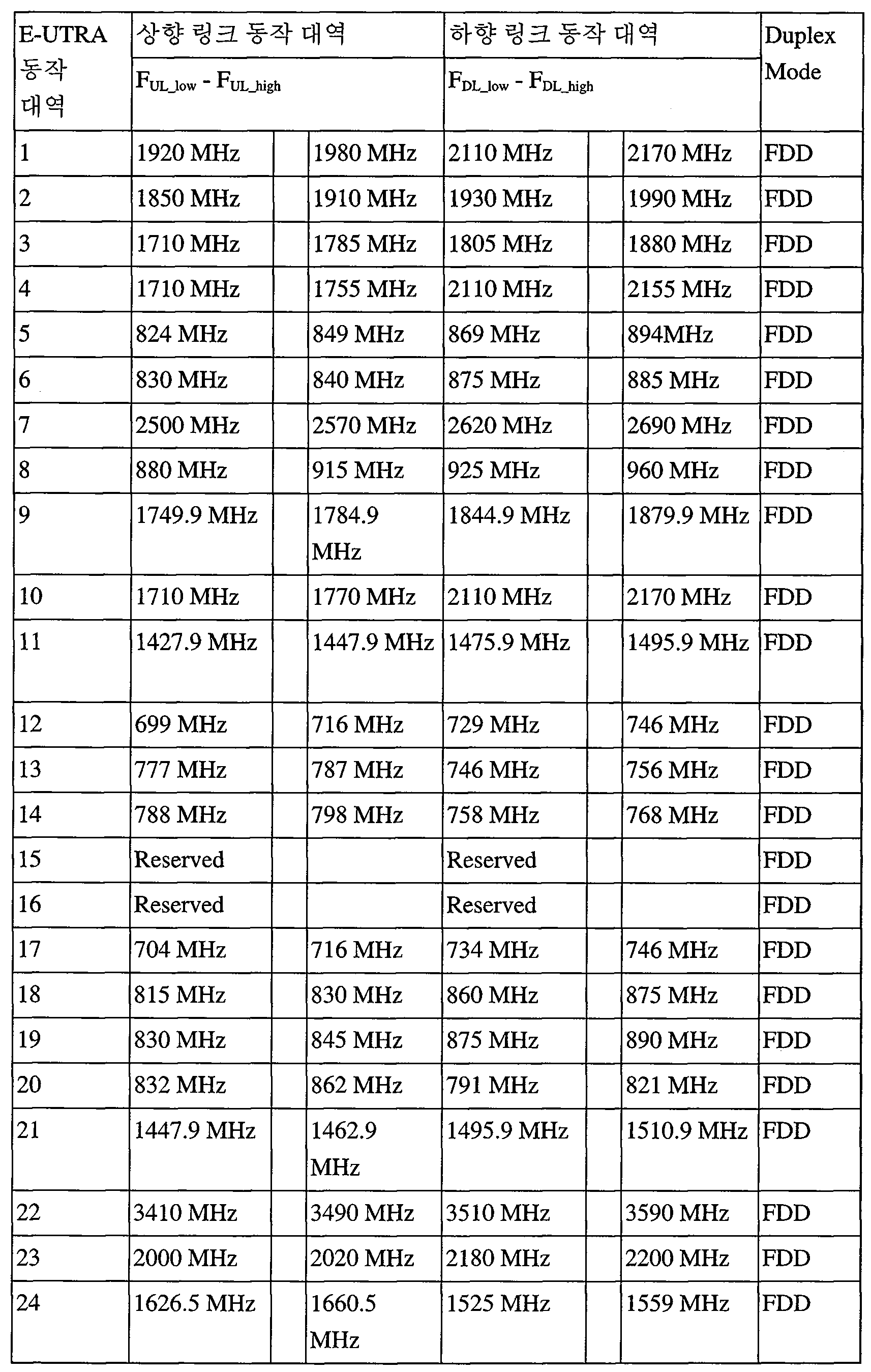
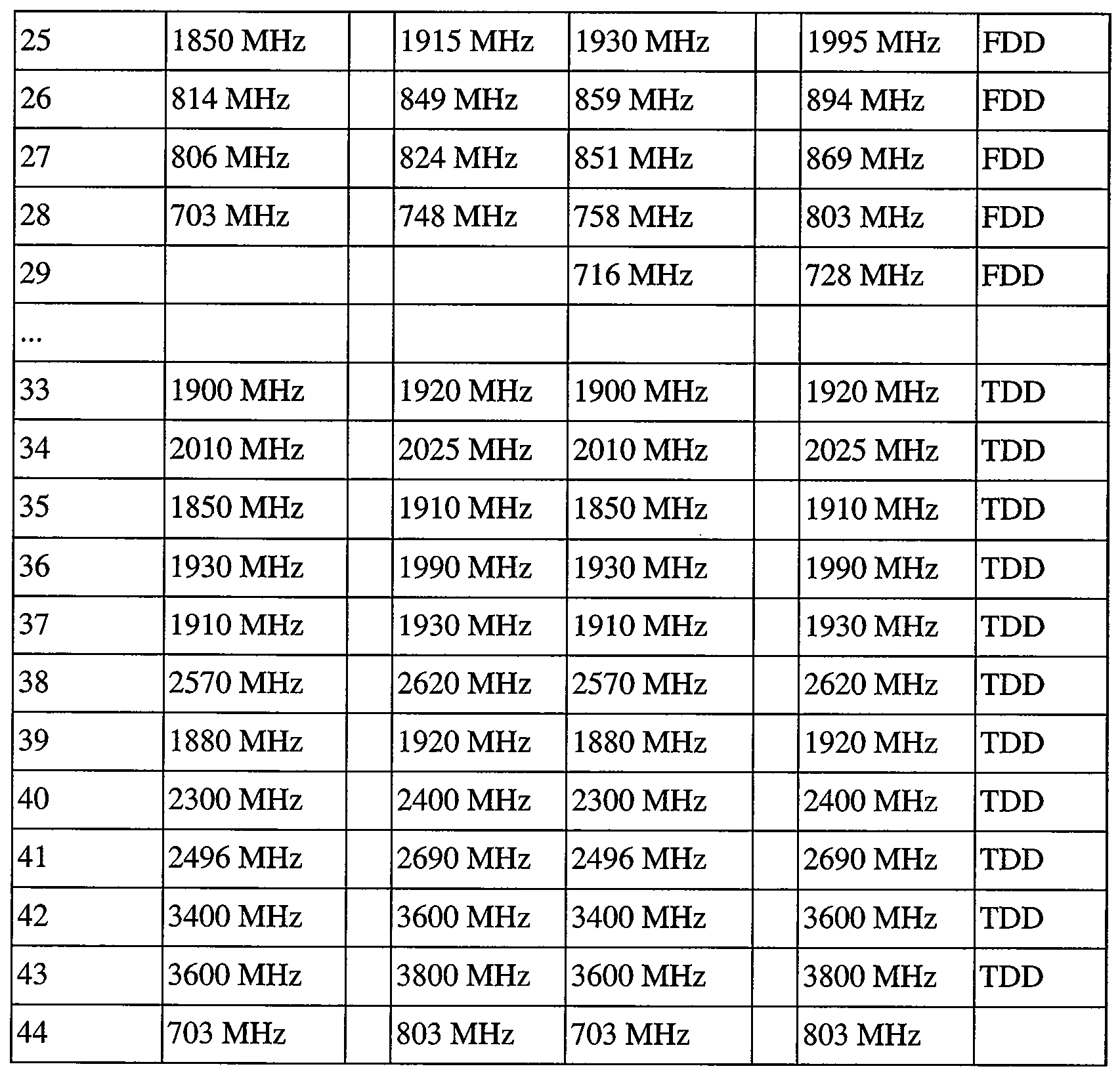
여기서 FUL _ low는 상향 링크 동작 대역의 가장 낮은 주파수를 의미한다. 그리고, FUL _ high는 상향링크 동작 대역의 가장 높은 주파수를 의미한다. 또한, FDL _ low는 하향 링크 동작 대역의 가장 낮은 주파수를 의미한다. 그리고, FDL _ high는 하향링크 동작 대역의 가장 높은 주파수를 의미한다.Here, F UL _ low means the lowest frequency of the uplink operating band. And, F UL _ high refers to the highest frequency of the up-link band of operation. In addition, low F DL _ refers to the lowest frequency of the DL band of operation. And, F DL _ high refers to the highest frequency of the down-link band of operation.
표 1과 같이 동작 대역이 정해져 있을 때, 각 국가의 주파수 배분 기구는 각국의 상황에 맞추어 서비스 사업자에게 특정 주파수를 배정할 수 있다.When the operating band is fixed as shown in Table 1, each country's frequency allocation mechanism can allocate a specific frequency to the service provider according to the situation of each country.
도 11(a)을 참조하면, 사업자 A가 동작 대역 19의 상향링크는 830 MHz~845 MHz와 하향 링크는 875 MHz~890 MHz를 배정받아 서비스 중이고, 사업자 B는 동작 대역 8의 상향링크 중 일부인 900 MHz~915 MHz, 하향링크 중 일부인 940 MHz~960 MHz를 배정받아 사용중이다.Referring to FIG. 11 (a), the carrier A is in the service of 830 MHz to 845 MHz in the uplink of the operating
이와 같은 상황에서 도 11(b)에 도시된 바와 같이, 사업자A와 사업자 B가 특정 지역에서 동시에 서비스를 수행하는 경우, 사업자 B의 단말이 기지국으로 전송하는 상향링크(예컨대, 900-915MHz 대역)의 스퓨리어스 방사가 사업자 A의 단말의 수신 대역(예컨대, 875-890MHz 대역)에 간섭을 주게 된다. 또한 사업자 A의 기지국이 단말로 전송하는 하향링크(예컨대, 875-890MHz 대역)에 의한 스퓨리어스 방사는 사업자 B의 기지국 수신대역(예컨대, 900-915MHz)에 간섭을 주게 된다. 즉, 서로 인접한 대역으로 불요 방사(unwanted emission)가 발생하게 된다. 이 중에서 하향링크 대역에서의 기지국 송신 스퓨리어스 방사에 의한 간섭은, 기지국의 특성상 고가와 큰 크기의 RF 필터 설계 등에 의해 인접 대역 기지국 수신 대역으로 인입되는 간섭양을 허용된 기준 이하로 줄일 수 있다. 반면 단말의 경우, 단말 크기의 제한, 전력 증폭기나 전치 듀플렉스 필터 RF 소자에 대한 가격 제한 등으로 인해 스퓨리어스 방사에 의한 간섭이 인접 대역 단말 수신 대역으로 인입되는 것을 완벽히 막기 어렵다. 특히 이 현상은 간섭을 주는 단말 송신 대역과 간섭을 받는 단말 수신 대역이 가까울 경우 더욱 심각하다.11 (b), when the service provider A and the service provider B simultaneously perform services in a specific area, the uplink (e.g., 900-915 MHz band) transmitted by the terminal of the service provider B to the base station, (E.g., the 875-890 MHz band) of the terminal of the carrier A is interfered with. In addition, the spurious emission by the downlink (for example, 875-890 MHz band) transmitted by the base station of the carrier A to the terminal gives interference to the base station reception band of the carrier B (for example, 900-915 MHz). That is, unwanted emission occurs in adjacent bands. Among them, the interference due to the base station transmission spurious domain radiation in the downlink band can be reduced below the allowable level due to the characteristics of the base station and the amount of interference introduced into the adjacent band base station reception band by RF filter design with a large size. On the other hand, in the case of the terminal, it is difficult to completely prevent the interference caused by the spurious radiation due to the restriction of the terminal size, the price limit for the power amplifier or the front duplex filter RF device, to the reception band of the adjacent band terminal. Especially, this phenomenon is more serious when the interfering terminal transmitting band and the interfering terminal receiving band are close to each other.
따라서, 단말 스퓨리어스 방사에 의한 간섭양이 허용치를 넘지 않도록 하기 위하여 단말 전송 전력 또는 전송 리소스 블록 할당 개수를 제한할 방안이 필요하다. 그러나, 전술한 바와 같이, 전송 전력이나 할당 리소스 블록 개수를 단순히 줄이게 되면, 서비스 커버리지도 줄어들게 되므로, 간섭 문제를 야기하지 않는 범위 내에서 최대 송신 전력 혹은 최대 전송 리소스 블록을 할당 함으로써, 적정한 수준으로 전송 전력을 줄이는 방안이 필요하다.Therefore, in order to prevent the amount of interference due to terminal spurious domain radiation from exceeding the tolerance, it is necessary to limit the terminal transmission power or the number of transmission resource block allocation. However, as described above, simply reducing the transmission power or the number of allocated resource blocks reduces the service coverage. Therefore, by allocating the maximum transmission power or the maximum transmission resource block within a range that does not cause an interference problem, .
이와 같이 전송 전력이나 전송 리소스 블록을 제한하는 방안을 설명하기 앞서, 단말이 실제로 사용 가능한 최대 전력(Pcmax)을 간단히 표현하면 다음과 같다.Before explaining how to restrict the transmission power and the transmission resource block, the maximum power Pcmax that can actually be used by the terminal will be briefly described as follows.
![]()
![]()
여기서 Pcmax는 단말이 해당 셀에서 송신 가능한 최대 전력 (실제 최대 송신 전력)을 의미하며, Pemax는 기지국이 시그널링하는 해당 셀 내에서 사용 가능한 최대 전력을 의미한다. 또한, Pumax는 단말 자체의 최대 전력(PPowerClass)에 최대 전력 감소량(Maximum Power Reduction; 이하 MPR), 추가 최대 전력 감소량(Additive-MPR; 이하 A-MPR) 등을 고려한 전력을 지칭한다.Here, Pcmax denotes the maximum power (actual maximum transmission power) that the UE can transmit in the corresponding cell, and Pemax denotes the maximum power that can be used in the corresponding cell to which the base station signals. Pumax refers to the power considering the maximum power reduction (MPR) and the additive-MPR (A-MPR) to the maximum power (P PowerClass ) of the terminal itself.
상기 최대 출력 파워는 채널 대역과, CA 여부, 상향링크 MIMO 여부에 따라 다르다.The maximum output power differs depending on the channel band, the presence of the CA, and the uplink MIMO.
먼저, CA와 MIMO를 사용하지 않을 때, 최대 출력 파워는 아래의 표 2와 같다.First, when CA and MIMO are not used, the maximum output power is shown in Table 2 below.
표 2Table 2

위에서, dBm은 전력(Watt)를 나타내는 단위로서, 1mW=0dBm이다.In the above, dBm is a unit of power (Watt) and is 1 mW = 0 dBm.
위와 같이 현재 LTE 시스템에서 단말 자체의 최대 전력(PPowerClass)은 출력 클래스(Power Class) 3으로 정의되어 있으며 이는 23dBm의 전력을 의미한다.As described above, in the current LTE system, the maximum power (P PowerClass ) of the terminal itself is defined as an output class (Power Class) 3, which means power of 23 dBm.
위와 같은 상기 최대 출력 파워는 각 UE의 안테나에서 하나의 서브 프레임 길이(1ms) 동안 측정되는 값을 표현한 것이다.The maximum output power as described above represents a value measured for one subframe length (1 ms) at the antenna of each UE.
반면, 단말이 MIMO를 위해 2개의 전송 안테나를 통해 구비하고, 폐루브 공간 다중화 스킴(spatial multiplexing scheme)을 사용할 때, 최대 전송 출력은 아래의 표 3과 같다.On the other hand, when the UE is provided with two transmission antennas for MIMO and uses a closed-loop spatial multiplexing scheme, the maximum transmission power is shown in Table 3 below.
표 3Table 3
위 표 2 및 3을 통해 알 수 있는 바와 같이, 단말 자체의 최대 전력(PPowerClass)은 23dBm이다.As can be seen from Tables 2 and 3 above, the maximum power of the terminal itself (PPowerClass) is 23 dBm.
이하에서는 인접한 대역 간에 서로 미치는 영향에 대해서 보다 상세하게 설명하기로 한다.Hereinafter, the influence of adjacent bands on each other will be described in more detail.
도 12은 불요 방사(unwanted emission)의 개념을 나타내며, 도 13은 도 12에 도시된 불요 방사 중 외부 대역에서의 방사를 구체적으로 나타내고, 도 14은 도 12에 도시된 채널 대역(MHz)와 리소스 블록(RB)의 관계를 나타낸다.Fig. 12 shows the concept of unwanted emission, Fig. 13 specifically shows the emission in the outer band of the spurious emission shown in Fig. 12, Fig. 14 shows the relationship between the channel band (MHz) Block (RB).
도 12를 참조하여 알 수 있는 바와 같이, 임의의 송신기가 임의의 E-UTRA 대역 내에서 할당된 채널 대역폭 상에서 신호를 전송한다.As can be seen with reference to FIG. 12, any transmitter transmits signals on the assigned channel bandwidth within any E-UTRA band.
여기서, 채널 대역폭은 도 14를 참조하여 알 수 있는 바와 같이, 정의된다. 즉, 채널 대역폭(BWChannel ) 보다 작게 전송 대역폭 설정이 이루어진다. 전송 대역폭 설정은 복수의 리소스 블록(Resource Block: RB)들에 의해 이루어진다. 그리고 채널 외곽은 채널 대역폭에 의해 분리된 가장 높고 낮은 주파수이다.Here, the channel bandwidth is defined, as can be seen with reference to FIG. That is, the transmission bandwidth is set smaller than the channel bandwidth (BW Channel ) . The transmission bandwidth setting is performed by a plurality of resource blocks (RBs). And the channel outline is the highest and lowest frequency separated by the channel bandwidth.
한편, 전술한 바와 같이 3GPP LTE 시스템에서는 채널 대역폭으로 1.4MHz, 3MHz, 5MHz, 10MHz, 15MHz 및 20MHz을 지원한다. 이러한 채널 대역폭과 리소스 블록의 개수의 관계는 아래의 표와 같다.Meanwhile, as described above, the 3GPP LTE system supports 1.4MHz, 3MHz, 5MHz, 10MHz, 15MHz and 20MHz as channel bandwidths. The relationship between the channel bandwidth and the number of resource blocks is shown in the following table.
표 4Table 4

다시 도 12를 참조하면, △fOOB의 대역에서 불요 방사가 생기고, 또한 도시된 바와 같이, 스퓨리어스(Spurious) 영역 상에서도 불요 방사가 생긴다. 여기서, fOOB는 외부 대역(Out Of Band: OOB)의 주파수의 크기를 의미한다. 한편, 외부 대역(Out Of Band) 상의 방사(emission)는 의도된 전송 대역과 근접한 대역에서 발생하는 것을 말한다. 스퓨리어스 방사란 의도된 전송 대역으로부터 멀리 떨어진 주파수 대역까지 불요파가 방사되는 것을 말한다.Referring again to Fig. 12, spurious emission occurs in the band of [Delta] f OOB and spurious emission also occurs in the spurious domain as shown. Here, f OOB denotes a frequency of an Out Of Band (OOB). On the other hand, emission on the out-of-band means that the emission occurs in a band close to the intended transmission band. Spurious radiation refers to the emission of unwanted waves up to the frequency band far from the intended transmission band.
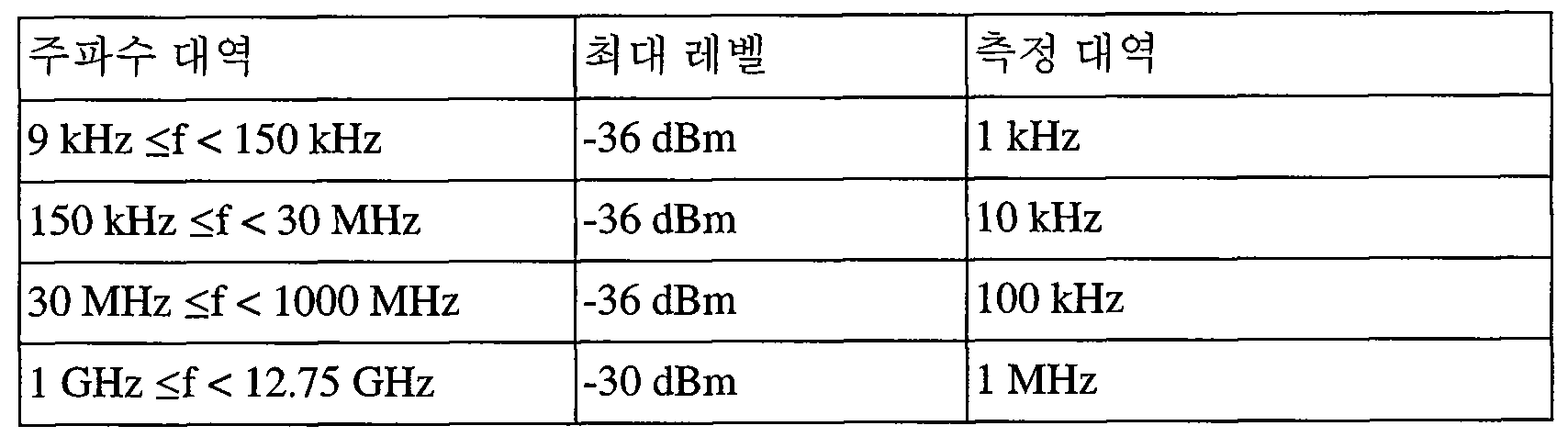
한편, 3GPP 릴리즈 10은 주파수 범위에 따라 최소한으로 넘지말아야 할 기본적인 SE(Spurious emission)을 정의하고 있다. 이를 표로 나타내면 다음과 같다.
표 5Table 5
한편, 도 13에 나타난 바와 같이, E-UTRA 채널 대역(1301)에서 전송을 수행하면, 외부 대역들(도시된 fOOB 영역내의 1302, 1303, 1304)으로 누설, 즉 불요 방사된다.On the other hand, as shown in FIG. 13, when transmission is performed in the
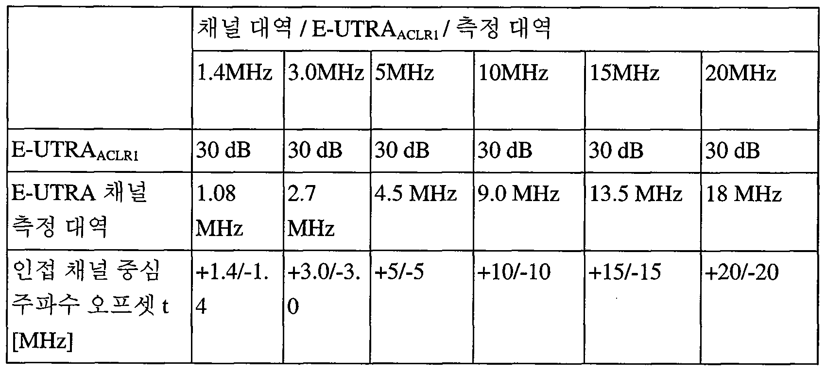
여기서, 도시된 UTRAACLR1은 단말이 E-UTRA 채널(1301)에서 전송을 할 때, 바로 인접한 채널(1302)이 UTRA를 위한 것일 경우, 상기 인접한 채널(1302), 즉 UTRA 채널로 누설되는 비율, 즉 인접 채널 누설비이다. 그리고, 상기 UTRAACLR2은 도 13에 나타난 바와 같이, 인접한 채널(1302) 옆에 위치하는 채널(1303)이 UTRA를 위한 것일 경우, 상기 인접한 채널(1303), 즉 UTRA 채널로 누설되는 비율, 즉 인접 채널 누설비이다. 그리고, 상기 E-UTRAACLR은 도 13에 나타난 바와 같이, 단말이 E-UTRA 채널(1301)에서 전송을 할 때, 인접한 채널(1304), 즉 E-UTRA 채널로 누설되는 비율, 즉 인접 채널 누설비이다.Herein, the UTRA ACLR1 shown in FIG. 13 indicates that, when the UE transmits on the
한편, 3GPP 릴리즈 10은 주파수 범위에 따라 최소한으로 넘지말아야 할 기본적인 요구 사항을 정의하고 있다. 이를 표로 나타내면 다음과 같다.
먼저, E-UTRA 대역을 위한 인접 채널 전력 누설비, 즉 E-UTRAACLR 아래의 표와 같다.First, the adjacent channel power leakage equipment for E-UTRA band, E-UTRA ACLR , is shown in the table below.
표 6Table 6
다음으로, UTRA 대역을 위한 인접 채널 전력 누설비, 즉 UTRAACLR 아래의 표 7과 같다.Next, the adjacent channel power leakage facilities for the UTRA band, that is, the UTRA ACLR, are shown in Table 7 below.
표 7Table 7

위 표에서 BWUTRA는 UTRA를 위한 채널 대역폭을 의미한다.In the above table, BW UTRA means channel bandwidth for UTRA.
이상에서 살펴본 바와 같이, 할당된 채널 대역에서 전송을 수행하면 인접한 채널들로 불요 방사가 일어난다. 따라서, 도 11에 나타난 예에서, 사업자 B의 단말이 기지국으로 전송하는 상향링크는 사업자 A의 단말 수신대역에 간섭을 주게 된다 . 또한 사업자 A의 기지국이 단말로 전송하는 하향링크는 사업자 B의 기지국 수신대역에 간섭을 주게 된다.As described above, if transmission is performed in the allocated channel band, unnecessary radiation occurs in adjacent channels. Therefore, in the example shown in FIG. 11, the uplink transmitted from the terminal of the terminal B to the base station interferes with the terminal reception band of the terminal A. In addition, the downlink transmitted by the base station of the carrier A to the mobile station interferes with the base station reception band of the carrier B.
이제, 본 발명의 일 양태에 따른 전송 전력 제어 방법을 실험 결과에 따라 설명하기로 한다.Now, a transmission power control method according to an aspect of the present invention will be described according to experimental results.
도 15는 전송 리소스 블록 제한를 위한 예시적인 첫 번째 실험 결과를 나타내고, 도 16은 도 15의 실험 결과를 다른 형태로 나타낸다.FIG. 15 shows an exemplary first experimental result for transmission resource block limitation, and FIG. 16 shows another experimental result of FIG.
RF 실험은 대표적인 가장 나쁜 실험 결과를 관찰하기 위해 단일 RB 할당, 부분적인 RB 할당 그리고 전체 RB 할당을 해봄으로써, 5 MHz (900-905Mhz) 및 10 MHz(905-915MHz) 채널 대역폭(CBW: Channel BandWidth) 에 대해서 수행하는 것으로 하였다. 이러한 실험을 통해, 채널 대역폭(CBW)에서 전송 대역폭 설정할 때, RB의 개수를 얼마만큼 줄이는 제한(limitation)을 하여야 하는지를 얻을 수 있다.The RF experiments were performed at 5 MHz (900-905 MHz) and 10 MHz (905-915 MHz) channel bandwidth (CBW) by observing a single RB allocation, a partial RB allocation and a full RB allocation to observe typical worst- ). Through these experiments, it is possible to obtain a limitation on how much the number of RBs can be reduced when the transmission bandwidth is set in the channel bandwidth (CBW).
모의 실험을 위해 사전에 정의한 RF 부품의 동작 점은 다음과 같다;The operating points of the RF components previously defined for the simulation are as follows;
- 모듈레이터:- Modulator:
이미지 제거(image rejection) = -25 dBcImage rejection = -25 dBc
캐리어 누설(Carrier leakage) =-25dBcCarrier leakage = -25dBc
Counter IM3 = -60 dBcCounter IM3 = -60 dBc
- PA :- PA:
UTRAACLR1 = 33 dBcUTRAACLR1 = 33 dBc
UTRAACLR2 = 36 dBc (1 dB MPR과 전체 RB 할당을 위함)UTRAACLR2 = 36 dBc (for 1 dB MPR and full RB allocation)
- 듀플렉서 감쇄는 고려안함- Duplexer attenuation is not considered
이때, 단위 dBc는 캐리어 주파수의 파워 크기를 기준으로 한 상대적인 크기를 나타낸다. 캐리어 누설(Carrier leakage)은 반송파 누설로서, 변조파 캐리어 주파수와 동일한 주파수를 갖는 부가적인 정현(사인)파형이다. Counter IM3(카운터 혼변조 왜곡)은 RF 시스템에서 혼합기와 증폭기 같은 컴포넌트에 의해 유발되는 요소를 나타낸다.In this case, the unit dBc represents a relative magnitude based on the power magnitude of the carrier frequency. Carrier leakage is carrier leakage and is an additional sinusoidal (sinusoidal) waveform with a frequency equal to the modulated wave carrier frequency. Counter IM3 (Counter Intermodulation Distortion) represents an element induced by components such as mixers and amplifiers in an RF system.
실험의 관측 주안점은 허용된 기준 스퓨리어스 방사를 기준으로 모의 실험 결과의 스퓨리어스 방사가 얼마만한 마진(Margin)을 갖는가에 있다. 여기서, 마진은 희생되는 하향링크 주파수 범위(즉, 875 ~ 890MHz)에서 -40dBm/MHz의 규제 요건 및 MHz당 측정된 파워 스펙트럼 밀도(dBm / MHz) 사이의 차이로 정의될 수 있다.The observation point of the experiment lies in how much margin the spurious radiation of the simulation results has on the basis of the allowed reference spurious radiation. Here, the margin can be defined as the difference between the regulatory requirement of -40 dBm / MHz in the sacrificing downlink frequency range (i.e., 875-890 MHz) and the power spectral density measured per MHz (dBm / MHz).
마진이 마이너스 값을 가지게 되면, 이는 상향링크에서 RB 할당에 한정(limitation)이 필요함을 의미하거나, 혹은 기본적인 최대 전력 감소량(Additional-MPR; 이하 A-MPR)외에도 추가 최대 전력 감소량(Additional-MPR; 이하 A-MPR)을 이용하여, 정해진 전송 전력 감소 보다 추가로 줄일 필요가 있다는 것을 의미한다.If the margin has a minus value, this means that a limitation is required in the RB allocation in the uplink or an additional MPR (Supplementary-MPR) in addition to the basic maximum power reduction amount (A-MPR) (A-MPR), it is necessary to further reduce the transmission power.
여기서, 상기 MPR은 표준에서 정의된 RF 요구사항(Spectrum Emission Mask(SEM), Adjacent Channel Leakage Ratio(ACLR), Spurious Emission(SE) 등)을 만족시키기 위해 특정 변조 차수(modulation order)나 RB(Resource Block)수에 대해 정의된 최대 송신 전력에 대한 전력 감소량이며, A-MPR은 지역적 특성으로 인해 정의된 최대 송신 전력에 대한 전력 감소량을 의미한다. 즉, A-MPR은 단말의 최대 전력을 추가로 더 감소시켜, 단말송신의 대역외 스퓨리어스 방사를 해당 국가에서 정해놓은 요구사항에 만족하는 수준으로 유도하는 것을 말한다.Here, the MPR may include a specific modulation order or a RB (resource allocation) rule to satisfy RF requirements defined in the standard (Spectrum Emission Mask (SEM), Adjacent Channel Leakage Ratio (ACLR) Block), and A-MPR is the power reduction amount for the maximum transmission power defined by the regional characteristics. That is, the A-MPR further reduces the maximum power of the terminal to derive the out-of-band spurious emissions of the terminal transmission to a level satisfying the requirements set in the corresponding country.
도 15를 참조하면, 905 MHz ~915MHz 사이의 10MHz를 채널 대역폭으로 할당하고, RB의 개수를 1개, 32개 50개로 증가시킬 때, PSD(Power Spectrum Density)와 해당하는 마진이 얼마인지가 나타난다.Referring to FIG. 15, when 10 MHz of 905 MHz to 915 MHz is allocated as the channel bandwidth and the number of RBs is increased to 1, 32, and 50, PSD (Power Spectrum Density) and corresponding margins are shown .
도 15의 실험 결과를 참조하면, 10MHz에 대해 전체 RB, 즉 50개 RB를 할당하는 경우, PSD는 -40dBm/MHz 초과하므로, RB의 제한이 필요한 것으로 나타난다.Referring to the experimental results in Fig. 15, when all RBs, i.e., 50 RBs, are allocated for 10 MHz, the PSD exceeds -40 dBm / MHz, so that a limitation of RB is required.
한편, 도 16을 참조하면, 905 MHz ~915MHz 사이의 10MHz를 채널 대역폭으로 할당하고, 단말 송신시 할당에서 제한할 RB의 개수를 1개에서 순차적으로 증가시킬 때, 스퓨리어스 방사 허용 기준 규격 -40dBm/MHz에 대한 마진이 얼마나 되는지가 나타나 있다. 도 16에서는 실험을 위해 제한할 RB의 개수는 0개(할당될 RB는 50개)에서부터 49개(할당된 RB 개수 1개)까지 증가시키는 식으로, 진행되었다. 즉, 실험은 채널 대역폭의 가장 오른쪽에 위치한 RB를 0개 제한하는 것부터 시작하여, 순차적으로 왼쪽으로 RB들을 추가 제한하는 식으로 진행된다. 이와 같이, 실험에서 RB의 제한은 채널 대역폭(CBW: Channel BandWidth)의 오른쪽으로부터 시작해서 왼쪽으로 진행되므로, 제한(limitation)하여 줄여야 하는 RB의 개수가 정해지면, 채널 대역폭(CBW: Channel BandWidth)의 왼쪽에서부터 정해진 개수의 RB가 사용되도록 할당(allocation)된다.16, when allocating 10 MHz between 905 MHz and 915 MHz as the channel bandwidth and sequentially increasing the number of RBs to be limited in the allocation upon terminal transmission, the spurious radiated emission standard of -40 dBm / The margin for MHz is shown. In FIG. 16, the number of RBs to be limited for the experiment is increased from 0 (50 RBs to be allocated) to 49 (1 assigned RB). That is, the experiment starts from limiting the RBs located at the rightmost position of the channel bandwidth, and sequentially restricting the RBs to the left. Thus, in the experiment, the limitation of the RB proceeds from the right side of the channel bandwidth (CBW) to the left. Therefore, when the number of RBs to be reduced is determined, the channel bandwidth (CBW) And a predetermined number of RBs are allocated from the left.
또한, 도 16을 참조하면, 8개의 RB를 제한시키면 마진이 좋아지기 시작하는 것처럼 보이기 시작하고, 18개의 RB를 제한시켜, 32개의 RB만 사용하도록 제한하면, 상당히 여유로운 수준인 1dB 정도까지의 마진을 확보할 수 있다.Referring to FIG. 16, limiting the eight RBs starts to appear to begin to improve, restricting the 18 RBs and limiting the use of only 32 RBs to a fairly relaxed level of 1 dB .
도 17은 전송 전력 제어를 위한 예시적인 두 번째 실험 결과를 나타내고, 도 18은 도 17의 실험 결과를 다른 형태로 나타낸다.FIG. 17 shows a second exemplary experimental result for the transmission power control, and FIG. 18 shows the experimental result of FIG. 17 in another form.
도 17를 참조하면, 905 MHz ~905MHz 사이의 5MHz를 채널 대역폭으로 할당하고, 할당한 RB의 개수를 1개, 20개, 25개로 증가시킬 때, PSD(Power Spectrum Density)와 해당하는 마진이 얼마인지가 나타난다.Referring to FIG. 17, when allocating 5 MHz between 905 MHz and 905 MHz as the channel bandwidth and increasing the number of allocated RBs to 1, 20, and 25, the power spectral density (PSD) Acknowledgment appears.
도 17의 실험 결과를 참조하면, 5MHz에 대해 전체 RB, 즉 25개 RB를 할당하는 경우, PSD는 -40dBm/MHz 초과하므로, RB의 제한이 필요한 것으로 나타난다.Referring to the experimental results in Fig. 17, when all RBs, i.e., 25 RBs, are allocated for 5 MHz, the PSD exceeds -40 dBm / MHz, so that the limitation of RB is required.
한편, 도 18을 참조하면, -40dBm/MHz 마스크를 충족하기 위해서는, 약 5개의 RB를 제한할 필요가 있는 것으로 나타난다.On the other hand, referring to FIG. 18, it appears that it is necessary to limit about 5 RBs in order to meet the -40 dBm / MHz mask.
이상 도 15 내지 도 18에 도시된 실험 결과를 표로 정리하면 아래와 같다.The experimental results shown in Figs. 15 to 18 are summarized in the following table.
표 8Table 8
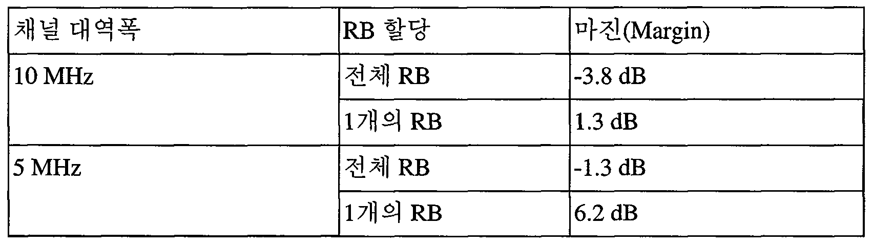
위의 표 8는 전체 RB 및 단일 RB 할당에 대한 마진을 나타낸다.Table 8 above shows the margins for total RB and single RB allocation.
표 9Table 9

표 9에 의하면 허용 최대 스퓨리어스 방사규격 -40dBm/MHz를 충족하기 위해, 10MHz와 5MHz의 채널대역폭(BWChannel)에 대해서 각각 약 18개 RB와 5개 RB를 제한하는 것이 필요한 것으로 나타난다.Table 9 shows that it is necessary to limit about 18 RB and 5 RB, respectively, for 10 MHz and 5 MHz channel bandwidths (BW Channels ) to meet the maximum spurious emission specification of -40 dBm / MHz.
다시 설명하면, 10 MHz에 대해서는 표 4에 도시된 바와 같이 원칙적으로 50개의 RB가 할당될 수 있지만, 18개의 RB를 제한시켜야 하므로, 최대 32개의 RB만이 할당될 수 있다. 또한, 5 MHz에 대해서는 표 4에 도시된 바와 같이 원칙적으로 25개의 RB가 할당될 수 있지만, 5개의 RB를 제한시켜야 하므로, 최대 20개의 RB만이 할당될 수 있다.In other words, 50 RBs can be allocated in principle as shown in Table 4 for 10 MHz. However, since 18 RBs should be limited, only a maximum of 32 RBs can be allocated. As shown in Table 4, although 25 RBs can be allocated in principle for 5 MHz, since 5 RBs must be limited, only a maximum of 20 RBs can be allocated.
한편, 위의 표 8 및 표 9를 수식으로 정리하면 다음과 같다.On the other hand, Table 8 and Table 9 are summarized as follows.
![]()
![]()
여기서 Nrestricted _ RB는 실제 이용할 수 있는 RB의 개수이고, Nfull RB of transmission bandwidth은 채널 대역폭을 구성하는 전송 대역폭의 전체 RB개수이다. 채널 대역폭이 10MHz이라면 전송 대역폭의 전체 RB는 50개이고, 채널 대역폭이 5MHz이라면, 전송 대역폭의 전체 RB는 25개이다.The restricted _ N RB is the number of RB available real, full N RB of The transmission bandwidth is the total number of RBs in the transmission bandwidth that make up the channel bandwidth. If the channel bandwidth is 10 MHz, the total RB of the transmission bandwidth is 50, and if the channel bandwidth is 5 MHz, the total RB of the transmission bandwidth is 25.
NRB _ limitation은 제한시킬 RB의 개수이다.N RB _ limitation is the number of limited to RB.
아래의 표는 각 E-UTRA 대역에서 보호될 대역과, 보호 대역에서의 허용 스퓨리어스 방사 규격 을 정리하여 나타낸다. 여기서, 각 주파수 범위의 외곽에서의 측정 조건에 대해서, 각 주파수 범위 내의 측정 위치의 최저 주파수는 주파수 범위+MBW/2의 최저 경계로 설정된다. 그리고, 각 주파수 범위에서 측정 위치의 최고 주파수는 주파수 범위-MBW/2의 최저 경계로 설정된다. MBW는 보호될 대역을 위한 측정 대역폭을 의미한다.The following table summarizes the band to be protected in each E-UTRA band and the permissible spurious radiation specification in the guard band. Here, with respect to the measurement conditions at the periphery of each frequency range, the lowest frequency of the measurement positions within each frequency range is set to the lowest boundary of the frequency range + MBW / 2. And, the highest frequency of the measurement position in each frequency range is set as the lowest boundary of the frequency range-MBW / 2. MBW means the measurement bandwidth for the band to be protected.
표 10Table 10
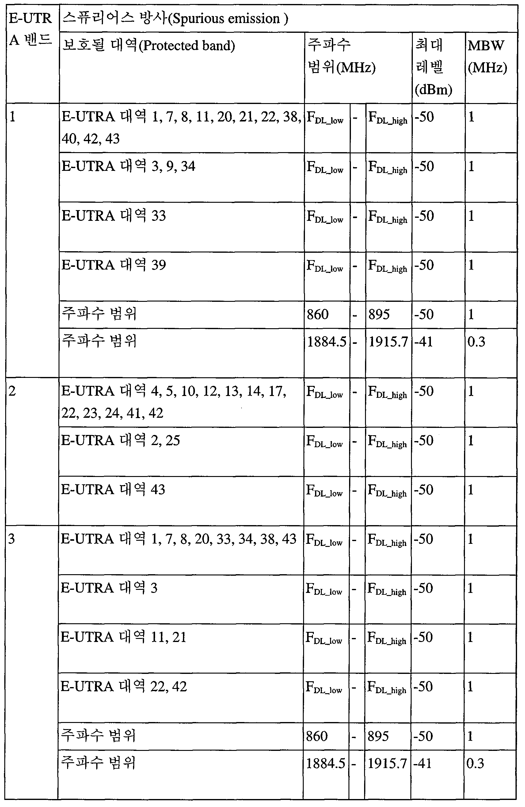


위의 표에서 E-UTRA 대역 8을 참조하면, 보호될 대역의 주파수 범위가 860MHz~890MHz인 경우, 스퓨리어스 방사는 -40dBm/MHz을 넘지 않아야 한다. 이를 충족하기 위해서는 902.5MHz = 중심주파수 (Fc) < 907.5 MHz에 해당하는 5MHz 채널 대역을 갖는 반송파에 대해서, 상향링크 전송 대역은 20개의 RB와 같거나 작아야 한다. 그리고, 중심주파수(Fc) 가 910MHz인 10MHz 채널 대역폭을 갖는 반송파에 대해서는, 상향링크 전송 대역은 32개의 RB와 같거나 작아야 한다.Referring to
이상의 실험 결과를 통해 알 수 있는 바와 같이, 어느 사업자에게 900 MHz 대역에서 서비스를 제공하고자 한다면, 인접한 대역에서 서비스를 제공중인 다른 사업자와 무리 없도록 하기 위해서는, 채널 대역폭에서 전체 RB를 사용하면 안되고, 할당할 RB 개수를 제한하여야 함을 알 수 있다.As can be seen from the above experimental results, in order to provide a service to a service provider in the 900 MHz band, it is necessary to not use the entire RB in the channel bandwidth and allocate It is necessary to limit the number of RBs.
그러므로, 기지국은 단말에게 상향링크 채널을 할당할 때, 채널 대역폭에서 몇 개의 RB를 제한시킴으로써, 모든 RB를 할당하지 않도록 해야 한다.Therefore, when allocating an uplink channel to a mobile station, a base station should limit a number of RBs in a channel bandwidth so that all RBs are not allocated.
지금까지는, 5 MHz (900-905Mhz) 및 10 MHz(905-915MHz) 채널 대역폭(CBW: Channel BandWidth)에서 스퓨리어스 방사를 줄이기 위해, 전송 대역폭을 설정하는 RB의 개수를 얼마만큼 제한해야 하는지에 대해서 설명하였다. 이하에서는, 동작에 대해서 설명하기로 한다.So far, we have discussed how to limit the number of RBs that set the transmission bandwidth to reduce spurious emissions at 5 MHz (900-905 MHz) and 10 MHz (905-915 MHz) Channel Bandwidth (CBW) Respectively. Hereinafter, the operation will be described.
도 19는 시스템 정보를 전달하는 과정을 나타낸다.19 shows a process of transmitting system information.
도 19(a)을 참조하면, 사업자A와 사업자 B가 특정 지역에서 동시에 서비스를 제공하는 예가 나타나 있다. 이때, 사업자 A가 동작 대역 19의 상향링크는 830 MHz~845 MHz와 하향 링크는 875 MHz~890 MHz를 배정받아 서비스 중이고, 사업자 B는 동작 대역 8의 상향링크 중 일부인 900 MHz~915 MHz, 하향링크 중 일부인 945 MHz~960 MHz를 배정받아 사용 중이라고 가정하자.Referring to FIG. 19 (a), an example is shown in which a provider A and a provider B simultaneously provide services in a specific area. In this case, the carrier A is in the service of 830 MHz to 845 MHz for the uplink of the
이와 같은 상황에서 도 19(b)에 도시된 바와 같이, 사업자 B의 기지국은 마스터 정보 블록(MIB: Master Information Block)과 시스템 정보 블록(SIB: System Information Block)을 전송한다.In this situation, as shown in FIG. 19B, the base station B transmits a Master Information Block (MIB) and a System Information Block (SIB).
상기 시스템 정보 블록(SIB)은 표 1에 도시된 동작 대역 중 자신이 사용중인 동작 대역 대한 정보와, 상향링크(Uplink: UL) 대역폭에 대한 정보와, 상향링크(UL) 캐리어 주파수에 대한 정보 중 하나 이상을 포함할 수 있다. 상기 상향링크(UL) 대역폭에 대한 정보는 자원 블록(RB: resource block)의 개수에 대한 정보를 포함할 수 있다.The system information block (SIB) includes information on an operating band in use, an information on an uplink (UL) bandwidth, and information on an uplink (UL) carrier frequency among the operating bands shown in Table 1 And may include one or more. The information on the uplink (UL) bandwidth may include information on the number of resource blocks (RBs).
따라서, 동작 대역이 위 표 1의 E-UTRA 대역 8이라면, 표 10을 참조하여 알 수 있는 바와 같이 인접하는 860MHz~890MHz 대역으로의 스퓨리어 방사를 최소하기 위해서 860~890MHz 대역에서의 스퓨리어스 방사는 -40dBm/MHz을 넘지 않아야 한다. 스퓨리어스 방사 허용치가 -40dBm/MHz를 넘지 않기 위해서는, 단말이 최대 전송 파워로 전송할 경우, 902.5MHz ≤ 중심주파수 (Fc) < 907.5 MHz에 해당하는 5MHz 채널 대역을 갖는 반송파에 대해서, 상향링크 전송 대역은 20개의 RB와 같거나 작아야 한다. 즉, 같이 채널 대역폭이 5MHz일 경우, 원칙적으로 25개의 RB가 할당될 수 있지만, 최소 약 5개의 RB가 제한된 최대 20개의 RB일 수 있다. 또한, 스퓨리어스 방사 허용치가 -40dBm/MHz을 넘지 않기 위해서는, 중심주파수(Fc) 가 910MHz인 10MHz 채널 대역폭을 갖는 반송파에 대해서는, 단말이 최대 전송 파워로 전송할 경우, 상향링크 전송 대역은 32개의 RB와 같거나 작아야 한다. 즉, 상기 RB의 개수는 전술한 바와 같이 채널 대역폭이 10MHz일 경우, 원칙적으로 50개의 RB가 할당될 수 있지만, 최소 18개의 RB가 제한된, 최대 32개의 RB일 수 있다.Therefore, if the operating band is the
도 19(c)을 참조하면, MIB, SIB, SI가 전송되는 서브프레임이 예시적으로 나타나있다. MIB와 SIB는 40ms와 80ms의 주기를 가지고 각기 전송된다. SI 메시지들은 다른 주기를 가지고, 스케줄에 따라 전송된다. 도 19(c)에서는 예시적으로 SFN(System Frame Number)가 0인 무선 프레임 상에서 MIB, SIB, SI들이 모두 전송되는 것으로 나타내었다.Referring to FIG. 19 (c), a subframe in which MIB, SIB, and SI are transmitted is illustrated as an example. The MIB and SIB are transmitted with a period of 40ms and 80ms, respectively. SI messages have different periods and are transmitted according to a schedule. In FIG. 19 (c), MIB, SIB, and SI are all transmitted on a radio frame with an SFN (System Frame Number) of 0 as an example.
도 20은 단말이 상향링크 데이터를 전송하는 과정을 나타낸다.20 shows a process in which a UE transmits uplink data.
도 20(a)은 3GPP LTE에서 랜덤 액세스 과정을 나타낸 흐름도이다. 랜덤 액세스 과정은 단말이 상향링크 무선 자원을 할당 받기 위해 사용된다. 랜덤 액세스 과정을 통해 RRC 연결이 초기설정(initialize)된다.20 (a) is a flowchart showing a random access procedure in 3GPP LTE. The random access procedure is used for the UE to allocate uplink radio resources. The RRC connection is initialized through the random access procedure.
먼저, 단말은 랜덤 액세스 과정을 수행하기 앞서, 루트 인덱스(root index)와 PRACH(physical random access channel) 설정 인덱스(configuration index)를 기지국으로부터 수신한다. 각 셀마다 ZC(Zadoff-Chu) 시퀀스에 의해 정의되는 64개의 후보(candidate) 랜덤 액세스 프리앰블이 있으며, 루트 인덱스는 단말이 64개의 후보 랜덤 액세스 프리앰블을 생성하기 위한 논리적 인덱스이다.First, the UE receives a root index and a physical random access channel (PRACH) configuration index from the BS before performing the random access procedure. Each cell has 64 candidate random access preambles defined by a Zadoff-Chu (ZC) sequence, and the root index is a logical index for the UE to generate 64 candidate random access preambles.
랜덤 액세스 프리앰블의 전송은 각 셀마다 특정 시간 및 주파수 자원에 한정된다. PRACH 설정 인덱스는 랜덤 액세스 프리앰블의 전송이 가능한 특정 서브프레임과 프리앰블 포맷을 지시한다.The transmission of the random access preamble is limited to specific time and frequency resources for each cell. The PRACH setting index indicates a specific subframe and a preamble format in which a random access preamble can be transmitted.
단말은 임의로 선택된 랜덤 액세스 프리앰블을 기지국으로 전송한다(S2010). 단말은 64개의 후보 랜덤 액세스 프리앰블 중 하나를 선택한다. 그리고, PRACH 설정 인덱스에 의해 해당되는 서브프레임을 선택한다. 단말은 선택된 랜덤 액세스 프리앰블을 선택된 서브프레임에서 전송한다.The UE transmits the randomly selected random access preamble to the base station (S2010). The terminal selects one of 64 candidate random access preambles. Then, the corresponding subframe is selected by the PRACH setting index. The terminal transmits the selected random access preamble in the selected subframe.
상기 랜덤 액세스 프리앰블을 수신한 기지국은 랜덤 액세스 응답(random access response, RAR)을 단말로 보낸다(S2020). 랜덤 액세스 응답은 2단계로 검출된다. 먼저 단말은 RA-RNTI(random access-RNTI)로 마스킹된 PDCCH를 검출한다. 그리고, 검출된 PDCCH 상의 DL 그랜트에 의해 지시되는 PDSCH 상으로 MAC(Medium Access Control) PDU(Protocol Data Unit) 내의 랜덤 액세스 응답을 수신한다.The base station receiving the random access preamble sends a random access response (RAR) to the mobile station (S2020). The random access response is detected in two steps. First, the UE detects a PDCCH masked with a random access-RNTI (RA-RNTI). And receives a random access response in a MAC (Medium Access Control) PDU (Protocol Data Unit) on the PDSCH indicated by the DL grant on the detected PDCCH.
도 20(b)은 랜덤 액세스 응답의 일 예를 나타낸다.20 (b) shows an example of a random access response.
랜덤 액세스 응답은 TAC(Timing Advance Command), UL 그랜트, 임시 C-RNTI를 포함할 수 있다.The random access response may include a TAC (Timing Advance Command), an UL grant, and a temporary C-RNTI.
TAC는 기지국이 단말에게 UL 시간 동기(time alignment)를 유지하기 위해 보내는 시간 동기 값을 지시하는 정보이다. 단말은 상기 시간 동기 값을 이용하여, UL 전송 타이밍을 갱신한다. 단말이 시간 동기를 갱신하면, 시간 동기 타이머(Time Alignment Timer)를 개시 또는 재시작한다. 시간 동기 타이머가 동작 중일 때만 단말은 UL 전송이 가능하다.The TAC is information indicating a time synchronization value that the BS sends to the UE to maintain UL time alignment. The terminal updates the UL transmission timing using the time synchronization value. When the UE updates the time synchronization, it starts or restarts the Time Alignment Timer. The terminal can transmit UL only when the time synchronization timer is in operation.
UL 그랜트는 스케줄링 메시지의 전송에 사용되는 UL 자원이다.The UL grant is a UL resource used for transmission of a scheduling message.
다시 도 20(a)를 참조하면, 단말은 랜덤 액세스 응답 내의 UL 그랜트에 따라 스케줄링된 메시지를 기지국으로 전송한다(S2030). 이때, 단말이 전송할 상기 스케줄링 메시지가 전송되는 상향링크 동작 대역이 위 표 1의 E-UTRA 대역 8이라면, 표 10을 참조하여 알 수 있는 바와 같이 인접하는 860MHz~890MHz 대역으로의 스퓨리어 방사를 최소하기 위해서 단말의 860Mhz~890MHz에서의 스퓨리어스 방사는 -40dBm/MHz을 넘지 않아야 한다. 이와 같이 스퓨리어스 방사가 -40dBm/MHz을 넘지 않도록 전송하기 위해서는, 단말이 최대 전송 파워로 전송할 경우, 902.5MHz ≤ 중심주파수 (Fc) < 907.5 MHz에 해당하는 5MHz 채널 대역을 갖는 반송파에 대해서, 상향링크 전송 대역은 20개의 RB와 같거나 작아야 한다. 즉, 같이 채널 대역폭이 5MHz일 경우, 원칙적으로 25개의 RB가 할당될 수 있지만, 최소 약 5개의 RB가 제한된 최대 20개의 RB일 수 있다. 또한, 860Mhz~890MHz에서의 스퓨리어스 방사 는 -40dBm/MHz을 넘지 않기 위해서는, 단말이 최대 전송 파워로 전송할 경우, 중심주파수(Fc) 가 910MHz인 10MHz 채널 대역폭을 갖는 반송파에 대해서는, 상향링크 전송 대역은 32개의 RB와 같거나 작아야 한다. 즉, 상기 RB의 개수는 전술한 바와 같이 채널 대역폭이 10MHz일 경우, 원칙적으로 50개의 RB가 할당될 수 있지만, 최소 약 18개의 RB가 제한된, 최대 32개의 RB일 수 있다.Referring back to FIG. 20 (a), the UE transmits a message scheduled according to the UL grant in the random access response to the base station (S2030). In this case, if the uplink operation band to which the UE transmits a scheduling message is the
본 발명의 실시예들은 다양한 수단을 통해 구현될 수 있다. 예를 들어, 본 발명의 실시예들은 하드웨어, 펌웨어(firmware), 소프트웨어 또는 그것들의 결합 등에 의해 구현될 수 있다.Embodiments of the present invention may be implemented by various means. For example, embodiments of the present invention may be implemented by hardware, firmware, software, or a combination thereof.
하드웨어에 의한 구현의 경우, 본 발명의 실시예들에 따른 방법은 하나 또는 그 이상의 ASICs(application specific integrated circuits), DSPs(digital signal processors), DSPDs(digital signal processing devices), PLDs(programmable logic devices), FPGAs(field programmable gate arrays), 프로세서, 콘트롤러, 마이크로 콘트롤러, 마이크로 프로세서 등에 의해 구현될 수 있다.For a hardware implementation, the method according to embodiments of the present invention may be implemented in one or more application specific integrated circuits (ASICs), digital signal processors (DSPs), digital signal processing devices (DSPDs), programmable logic devices (PLDs) , Field programmable gate arrays (FPGAs), processors, controllers, microcontrollers, microprocessors, and the like.
펌웨어나 소프트웨어에 의한 구현의 경우, 본 발명의 실시예들에 따른 방법은 이상에서 설명된 기능 또는 동작들을 수행하는 모듈, 절차 또는 함수 등의 형태로 구현될 수 있다. 소프트웨어 코드는 메모리 유닛에 저장되어 프로세서에 의해 구동될 수 있다. 상기 메모리 유닛은 상기 프로세서 내부 또는 외부에 위치하여, 이미 공지된 다양한 수단에 의해 상기 프로세서와 데이터를 주고 받을 수 있다. 구체적으로는 도 21을 참조하여 설명하기로 한다.In the case of an implementation by firmware or software, the method according to embodiments of the present invention may be implemented in the form of a module, a procedure or a function for performing the functions or operations described above. The software code can be stored in a memory unit and driven by the processor. The memory unit may be located inside or outside the processor, and may exchange data with the processor by various well-known means. More specifically, it will be described with reference to FIG.
도 21은 본 발명의 실시예가 구현되는 무선통신 시스템을 나타낸 블록도이다.21 is a block diagram illustrating a wireless communication system in which an embodiment of the present invention is implemented.
기지국(200)은 프로세서(processor, 201), 메모리(memory, 202) 및 RF부(RF(radio frequency) unit, 203)을 포함한다. 메모리(202)는 프로세서(201)와 연결되어, 프로세서(201)를 구동하기 위한 다양한 정보를 저장한다. RF부(203)는 프로세서(201)와 연결되어, 무선 신호를 송신 및/또는 수신한다. 프로세서(201)는 제안된 기능, 과정 및/또는 방법을 구현한다. 전술한 실시 예에서 기지국의 동작은 프로세서(51)에 의해 구현될 수 있다.The
무선기기(100)는 프로세서(101), 메모리(102) 및 RF부(103)을 포함한다. 메모리(102)는 프로세서(101)와 연결되어, 프로세서(101)를 구동하기 위한 다양한 정보를 저장한다. RF부(103)는 프로세서(101)와 연결되어, 무선 신호를 송신 및/또는 수신한다. 프로세서(101)는 제안된 기능, 과정 및/또는 방법을 구현한다. 전술한 실시 예에서 무선기기의 동작은 프로세서(101)에 의해 구현될 수 있다.The
프로세서는 ASIC(application-specific integrated circuit), 다른 칩셋, 논리 회로 및/또는 데이터 처리 장치를 포함할 수 있다. 메모리는 ROM(read-only memory), RAM(random access memory), 플래쉬 메모리, 메모리 카드, 저장 매체 및/또는 다른 저장 장치를 포함할 수 있다. RF부는 무선 신호를 처리하기 위한 베이스밴드 회로를 포함할 수 있다. 실시 예가 소프트웨어로 구현될 때, 상술한 기법은 상술한 기능을 수행하는 모듈(과정, 기능 등)로 구현될 수 있다. 모듈은 메모리에 저장되고, 프로세서에 의해 실행될 수 있다. 메모리는 프로세서 내부 또는 외부에 있을 수 있고, 잘 알려진 다양한 수단으로 프로세서와 연결될 수 있다.The processor may comprise an application-specific integrated circuit (ASIC), other chipset, logic circuitry and / or a data processing device. The memory may include read-only memory (ROM), random access memory (RAM), flash memory, memory cards, storage media, and / or other storage devices. The RF unit may include a baseband circuit for processing the radio signal. When the embodiment is implemented in software, the above-described techniques may be implemented with modules (processes, functions, and so on) that perform the functions described above. The module is stored in memory and can be executed by the processor. The memory may be internal or external to the processor and may be coupled to the processor by any of a variety of well known means.
상술한 예시적인 시스템에서, 방법들은 일련의 단계 또는 블록으로써 순서도를 기초로 설명되고 있지만, 본 발명은 단계들의 순서에 한정되는 것은 아니며, 어떤 단계는 상술한 바와 다른 단계와 다른 순서로 또는 동시에 발생할 수 있다. 또한, 당업자라면 순서도에 나타낸 단계들이 배타적이지 않고, 다른 단계가 포함되거나 순서도의 하나 또는 그 이상의 단계가 본 발명의 범위에 영향을 미치지 않고 삭제될 수 있음을 이해할 수 있을 것이다.In the above-described exemplary system, the methods are described on the basis of a flowchart as a series of steps or blocks, but the present invention is not limited to the order of the steps, and some steps may occur in different orders or simultaneously . It will also be understood by those skilled in the art that the steps shown in the flowchart are not exclusive and that other steps may be included or that one or more steps in the flowchart may be deleted without affecting the scope of the invention.
Claims (15)
프로세서와;
E-UTRA 대역을 지원하되, 상기 프로세서의 제어에 따라 상향링크 시그널을 전송하는 RF(Radio Frequency) 부를 포함하되,
상기 RF부가 미리 정해진 채널 대역폭 및 미리 정해진 주파수 범위로 설정되고, 그리고 다른 주파수 범위를 보호하기 위해 미리 정해진 스퓨리어스 방사의 최대 허용치를 충족시켜야 할 경우,
상기 미리 정해진 채널 대역폭을 위한 전체 개수의 리소스 블록(RB)들 대신에, 미리 정해진 최대 개수의 리소스 블록(RB)들에 따라, 상기 상향링크 시그널이 전송되는 것을 특징으로 하는 무선 기기.A wireless device for transmitting an uplink signal in a wireless communication system,
A processor;
And an RF (Radio Frequency) unit for supporting the E-UTRA band and transmitting an uplink signal under the control of the processor,
If the RF section is set to a predetermined channel bandwidth and a predetermined frequency range and the maximum allowable value of a predetermined spurious emission is to be met to protect the other frequency range,
Wherein the uplink signal is transmitted according to a predetermined maximum number of resource blocks (RBs) instead of a total number of resource blocks (RBs) for the predetermined channel bandwidth.
상기 미리 정해진 스퓨리어스 방사 허용치를 충족하기 위해, 상기 미리 정해진 채널 대역폭을 위한 전체 개수의 RB들 중에서 일부 개수의 리소스 블록(RB)을 감소시킴으로써 구해지는 것을 특징으로 하는 무선 기기.The method of claim 1, wherein the predetermined number is
(RB) of the total number of RBs for the predetermined channel bandwidth to meet the predetermined spurious emission tolerance. ≪ Desc / Clms Page number 19 >
상기 미리 정해진 채널 대역폭이 5MHz인 경우, 상기 RB의 전체 개수는 25이고,
상기 미리 정해진 채널 대역폭이 10 MHz인 경우, 상기 RB의 전체 개수는 50인 것을 특징으로 하는 무선 기기.3. The method of claim 2,
If the predetermined channel bandwidth is 5 MHz, the total number of RBs is 25,
Wherein the total number of RBs is 50 when the predetermined channel bandwidth is 10 MHz.
상기 미리 정해진 채널 대역폭이 5 MHz인 경우, 상기 미리 정해진 RB들의 개수는 상기 전체 RB의 개수인 25 개에서 제한해야 할 5개를 감소시킴으로써 구해진 20보다 작거나 같고,
상기 미리 정해진 채널 대역폭이 10 MHz인 경우, 상기 미리 정해진 RB들의 개수는 상기 전체 RB의 개수인 50개에서 제한해야 할 18개를 감소시킴으로써 구해진 32개 보다 작거나 같아야 하는 것을 특징으로 하는 무선 기기.5. The method of claim 4,
When the predetermined channel bandwidth is 5 MHz, the number of the predetermined RBs is less than or equal to 20, which is obtained by decreasing the number of five to be limited from 25, which is the total number of RBs,
Wherein when the predetermined channel bandwidth is 10 MHz, the number of the predetermined RBs should be less than or equal to 32, which is obtained by decreasing the number of limitations from 50, which is the total number of RBs, to 18.
상기 미리 정해진 채널 대역폭이 5MHz인 경우, 상기 미리 정해진 RB들의 개수는 20보다 작거나 같고,
상기 미리 정해진 채널 대역폭이 10 MHz인 경우, 상기 미리 정해진 RB들의 개수는 32보다 작거나 같은 것을 특징으로 하는 무선 기기.The method according to claim 1,
When the predetermined channel bandwidth is 5 MHz, the number of the predetermined RBs is less than or equal to 20,
Wherein the predetermined number of RBs is less than or equal to 32 when the predetermined channel bandwidth is 10 MHz.
상향링크에 대해서 880MHz~915 MHz이고, 하향링크에 대해서 925 MHz~960 MHz인 것을 특징으로 하는 무선 기기.8. The method of claim 7, wherein according to the band 8, the predetermined frequency range is
Wherein the uplink frequency is 880 MHz to 915 MHz for the uplink and 925 MHz to 960 MHz for the downlink.
Nrestricted _ RB =Nfull RB of transmission bandwidth-NRB _ limitation에 의해서 산출되고,
여기서, Nfull RB of transmission bandwidth은 채널 대역폭을 구성하는 전송 대역폭의 전체 RB개수이고, NRB _ limitation는 미리 정해진 스퓨리어스 방사 허용치를 충족시키기 위해 제한될 RB의 개수인 것을 특징으로 하는 무선 기기.The method of claim 1, wherein when the number of the predetermined RB represented by N RB restricted _,
Restricted _ N = N RB full RB of transmission is calculated by the RB bandwidth -N _ limitation,
Here, N full RB of transmission RB bandwidth is the total number of bandwidth that make up the channel bandwidth, N RB _ limitation is the wireless device, characterized in that the number of RB to be limited in order to meet the predetermined spurious emission limit.
E-UTRA 대역을 지원하고, 무선 신호를 송신 및 수신하는 RF(Radio Frequency) 부와;
상기 RF부와 연결되어 제어하는 프로세서를 포함하되,
상기 프로세서는 상기 RF부가 미리 정해진 채널 대역폭 및 미리 정해진 주파수 범위로 설정되고, 그리고 다른 주파수 범위를 보호하기 위해 미리 정해진 스퓨리어스 방사의 최대 허용치를 충족시켜야 할 경우, 미리 정해진 채널 대역폭을 위한 전체 개수의 리소스 블록(RB)들 중에서 대신에, 미리 정해진 최대 개수의 리소스 블록(RB)들에 따라 상향링크 자원을 할당하는 것을 특징으로 하는 기지국.A base station for receiving an uplink signal in a wireless communication system,
An RF (Radio Frequency) unit for supporting the E-UTRA band and transmitting and receiving a radio signal;
And a processor coupled to and controlling the RF unit,
The processor is further configured to determine if the RF unit is set to a predetermined channel bandwidth and a predetermined frequency range and if the maximum allowable value of the predetermined spurious emissions is to be met to protect another frequency range, And allocates uplink resources according to a predetermined maximum number of resource blocks (RBs) instead of among the blocks (RBs).
상기 미리 정해진 스퓨리어스 방사 허용치를 충족하기 위해, 상기 미리 정해진 채널 대역폭을 위한 전체 개수의 RB들 중에서 일부 개수의 리소스 블록(RB)을 감소시킴으로써 구해지는 것을 특징으로 하는 기지국.11. The method of claim 10, wherein the predetermined number is
(RB) of the total number of RBs for the predetermined channel bandwidth to satisfy the predetermined spurious emission tolerance.
상기 미리 정해진 채널 대역폭이 5MHz인 경우, 상기 RB의 전체 개수는 25이고,
상기 미리 정해진 채널 대역폭이 10 MHz인 경우, 상기 RB의 전체 개수는 50인 것을 특징으로 하는 기지국.12. The method of claim 11,
If the predetermined channel bandwidth is 5 MHz, the total number of RBs is 25,
Wherein the total number of RBs is 50 when the predetermined channel bandwidth is 10 MHz.
상기 미리 정해진 채널 대역폭이 5 MHz인 경우, 상기 미리 정해진 RB들의 개수는 상기 전체 RB의 개수인 25 개에서 제한해야 할 5개를 감소시킴으로써 구해진 20보다 작거나 같고,
상기 미리 정해진 채널 대역폭이 10 MHz인 경우, 상기 미리 정해진 RB들의 개수는 상기 전체 RB의 개수인 50개에서 제한해야 할 18개를 감소시킴으로써 구해진 32개 보다 작거나 같아야 하는 것을 특징으로 하는 기지국.13. The method of claim 12,
When the predetermined channel bandwidth is 5 MHz, the number of the predetermined RBs is less than or equal to 20, which is obtained by decreasing the number of five to be limited from 25, which is the total number of RBs,
Wherein when the predetermined channel bandwidth is 10 MHz, the number of the predetermined RBs should be less than or equal to 32, which is obtained by decreasing the number of limitations from 50, which is the total number of RBs, to 18.
상기 미리 정해진 채널 대역폭이 5MHz인 경우, 상기 미리 정해진 RB들의 개수는 20보다 작거나 같고,
상기 미리 정해진 채널 대역폭이 10 MHz인 경우, 상기 미리 정해진 RB들의 개수는 32보다 작거나 같은 것을 특징으로 하는 기지국.11. The method of claim 10,
When the predetermined channel bandwidth is 5 MHz, the number of the predetermined RBs is less than or equal to 20,
Wherein the predetermined number of RBs is less than or equal to 32 when the predetermined channel bandwidth is 10 MHz.
Applications Claiming Priority (5)
| Application Number | Priority Date | Filing Date | Title |
|---|---|---|---|
| US201261647524P | 2012-05-16 | 2012-05-16 | |
| US61/647,524 | 2012-05-16 | ||
| US201361809886P | 2013-04-09 | 2013-04-09 | |
| US61/809,886 | 2013-04-09 | ||
| PCT/KR2013/004031 WO2013172585A1 (en) | 2012-05-16 | 2013-05-08 | Wireless equipment for transmitting uplink signal through reduced transmission resource block and power, and enodeb |
Publications (1)
| Publication Number | Publication Date |
|---|---|
| KR20140146593A true KR20140146593A (en) | 2014-12-26 |
Family
ID=49583949
Family Applications (1)
| Application Number | Title | Priority Date | Filing Date |
|---|---|---|---|
| KR1020147027046A KR20140146593A (en) | 2012-05-16 | 2013-05-08 | Wireless equipment for transmitting uplink signal through reduced transmission resource block and power, and enodeb |
Country Status (6)
| Country | Link |
|---|---|
| US (1) | US9736851B2 (en) |
| EP (1) | EP2852074B1 (en) |
| JP (1) | JP2015523771A (en) |
| KR (1) | KR20140146593A (en) |
| CN (1) | CN104541459B (en) |
| WO (1) | WO2013172585A1 (en) |
Cited By (1)
| Publication number | Priority date | Publication date | Assignee | Title |
|---|---|---|---|---|
| WO2020226377A1 (en) * | 2019-05-03 | 2020-11-12 | 엘지전자 주식회사 | Method whereby terminal transmits and receives signals for carrying out random access channel procedure in wireless communication system, and device therefor |
Families Citing this family (19)
| Publication number | Priority date | Publication date | Assignee | Title |
|---|---|---|---|---|
| EP3429295B1 (en) | 2013-08-07 | 2019-10-23 | Sun Patent Trust | Communication apparatus and method |
| EP3113560B1 (en) * | 2014-03-21 | 2022-04-20 | Huawei Technologies Co., Ltd. | Apparatus for configuring position of frequency resource |
| JP7066611B2 (en) | 2015-11-04 | 2022-05-13 | アイディーエーシー ホールディングス インコーポレイテッド | Multi-length ZT DFT-S-OFDM transmission |
| CN106921475B (en) * | 2015-12-25 | 2019-12-13 | 深圳市中兴微电子技术有限公司 | data receiving method and device |
| WO2018008916A2 (en) * | 2016-07-02 | 2018-01-11 | 엘지전자 주식회사 | Downlink signal reception method and user equipment, and downlink signal transmission method and base station |
| CN107872865B (en) | 2016-09-24 | 2019-05-17 | 上海朗帛通信技术有限公司 | A kind of method and apparatus of transmission power adjustment in UE, base station |
| EP4090095A1 (en) * | 2016-09-29 | 2022-11-16 | MediaTek Inc. | Method and apparatus for power consumption reduction in mobile communications |
| WO2018141213A1 (en) | 2017-02-03 | 2018-08-09 | Telefonaktiebolaget Lm Ericsson (Publ) | Method and device for performing uplink transmission |
| US11265877B2 (en) * | 2017-05-26 | 2022-03-01 | Lg Electronics Inc. | Method for selecting transmission resource for transport block by user equipment in wireless communication system and apparatus therefor |
| CN110651526B (en) * | 2017-07-31 | 2021-10-01 | 华为技术有限公司 | Fixed channel transmission method, device and communication device |
| CN107484192B (en) * | 2017-09-06 | 2021-01-26 | 中兴通讯股份有限公司 | Power processing method and device and storage medium |
| WO2019097116A1 (en) * | 2017-11-16 | 2019-05-23 | Nokia Technologies Oy | Maximum power reduction for uplink bandwidth part for wireless networks |
| KR102522056B1 (en) * | 2018-08-07 | 2023-04-14 | 삼성전자주식회사 | Method for controlling tranmission power of uplink tranmission and electronic device therefor |
| CN109041240A (en) * | 2018-08-09 | 2018-12-18 | 维沃移动通信有限公司 | A kind of method and mobile terminal improving signal interference |
| KR20200050852A (en) * | 2018-11-02 | 2020-05-12 | 삼성전자주식회사 | Method and apparatus for handling overheat of electronic apparatus |
| EP3879722B1 (en) * | 2019-07-29 | 2024-05-01 | ST Engineering iDirect (Europe) Cy NV | Satellite communication system |
| US11291014B1 (en) * | 2019-12-23 | 2022-03-29 | Motorola Solutions, Inc. | Device, system and method for radio-frequency emissions control |
| WO2023123346A1 (en) * | 2021-12-31 | 2023-07-06 | 华为技术有限公司 | Signal processing method and device, chip, and base station |
| US20230262732A1 (en) * | 2022-02-15 | 2023-08-17 | T-Mobile Innovations Llc | Systems and methods for broadcast control channel power boost scheduling for wireless communications base stations |
Family Cites Families (12)
| Publication number | Priority date | Publication date | Assignee | Title |
|---|---|---|---|---|
| US8145251B2 (en) * | 2006-01-23 | 2012-03-27 | Motorola Mobility, Inc. | Power control in schedulable wireless communication terminal |
| US20070173260A1 (en) * | 2006-01-23 | 2007-07-26 | Love Robert T | Wireless communication network scheduling |
| US20080025254A1 (en) | 2006-07-25 | 2008-01-31 | Motorola Inc | Spectrum emission level variation in schedulable wireless communication terminal |
| WO2008108228A1 (en) * | 2007-03-01 | 2008-09-12 | Ntt Docomo, Inc. | Base station device and communication control method |
| WO2010082888A1 (en) | 2009-01-14 | 2010-07-22 | Telefonaktiebolaget L M Ericsson (Publ) | Method and arrangement in a wireless communication system |
| EP2415318B1 (en) | 2009-03-31 | 2020-02-12 | Nokia Solutions and Networks Oy | Controlling ue emissions for avoiding self-interference and for demanding coexistence situations |
| US8055294B2 (en) | 2009-04-07 | 2011-11-08 | Lg Electronics Inc. | Control of uplink transmit power |
| JP5111536B2 (en) | 2009-04-27 | 2013-01-09 | 株式会社エヌ・ティ・ティ・ドコモ | User apparatus, base station apparatus, and communication control method |
| KR101697597B1 (en) | 2010-04-01 | 2017-01-18 | 엘지전자 주식회사 | Method and apparatus of controlling transmission power |
| KR101409108B1 (en) * | 2010-06-29 | 2014-06-17 | 엘지전자 주식회사 | Terminal, the transmission power of which is limited in accordance with an adjacent channel interference ratio |
| US9100781B2 (en) * | 2010-07-16 | 2015-08-04 | Lg Electronics Inc. | Method and apparatus for transmitting location estimation message in wireless communication system |
| WO2012036378A2 (en) * | 2010-09-17 | 2012-03-22 | 엘지전자 주식회사 | Method for resource scheduling using a carrier aggregation technique |
-
2013
- 2013-05-08 CN CN201380022319.8A patent/CN104541459B/en active Active
- 2013-05-08 WO PCT/KR2013/004031 patent/WO2013172585A1/en active Application Filing
- 2013-05-08 EP EP13790088.2A patent/EP2852074B1/en active Active
- 2013-05-08 KR KR1020147027046A patent/KR20140146593A/en not_active Application Discontinuation
- 2013-05-08 JP JP2015512568A patent/JP2015523771A/en active Pending
- 2013-05-08 US US14/389,644 patent/US9736851B2/en active Active
Cited By (1)
| Publication number | Priority date | Publication date | Assignee | Title |
|---|---|---|---|---|
| WO2020226377A1 (en) * | 2019-05-03 | 2020-11-12 | 엘지전자 주식회사 | Method whereby terminal transmits and receives signals for carrying out random access channel procedure in wireless communication system, and device therefor |
Also Published As
| Publication number | Publication date |
|---|---|
| CN104541459A (en) | 2015-04-22 |
| JP2015523771A (en) | 2015-08-13 |
| US20150071203A1 (en) | 2015-03-12 |
| EP2852074A1 (en) | 2015-03-25 |
| US9736851B2 (en) | 2017-08-15 |
| CN104541459B (en) | 2018-02-13 |
| EP2852074A4 (en) | 2016-01-20 |
| WO2013172585A1 (en) | 2013-11-21 |
| EP2852074B1 (en) | 2019-02-13 |
Similar Documents
| Publication | Publication Date | Title |
|---|---|---|
| EP2852074B1 (en) | Wireless equipment for transmitting uplink signal through reduced number of transmission resource blocks, and base station | |
| KR101413351B1 (en) | Method for transmitting uplink signal using reduced number of resource blocks to prevent a deterioration of reference sensitivity in intra non-contiguous carrier aggregation and terminal thereof | |
| US9591589B2 (en) | Method and terminal for transmitting uplink signal by reduced power in intraband non-contiguous uplink carrier aggregation | |
| US9451560B2 (en) | Method for determining uplink transmission power | |
| US10205580B2 (en) | Method for transmitting uplink signal to minimize spurious emission and user equipment thereof | |
| KR102053232B1 (en) | Uplink transmission power determination method and wireless device | |
| US10375651B2 (en) | Uplink signal transmission method and user equipment capable of protecting neighboring band from mobile satellite service band | |
| KR20130063985A (en) | Method for reducing transmission power and a terminal thereof | |
| KR101545099B1 (en) | Method for determining an uplink transmission power |
Legal Events
| Date | Code | Title | Description |
|---|---|---|---|
| A201 | Request for examination | ||
| E902 | Notification of reason for refusal | ||
| E902 | Notification of reason for refusal | ||
| E601 | Decision to refuse application |