KR20140146118A - Multiple-input multiple-output antenna and broadband dipole radiating element therefore - Google Patents
Multiple-input multiple-output antenna and broadband dipole radiating element therefore Download PDFInfo
- Publication number
- KR20140146118A KR20140146118A KR20147029022A KR20147029022A KR20140146118A KR 20140146118 A KR20140146118 A KR 20140146118A KR 20147029022 A KR20147029022 A KR 20147029022A KR 20147029022 A KR20147029022 A KR 20147029022A KR 20140146118 A KR20140146118 A KR 20140146118A
- Authority
- KR
- South Korea
- Prior art keywords
- radiating element
- lip
- dipole radiating
- antenna
- dipole
- Prior art date
Links
Images


Classifications
-
- H—ELECTRICITY
- H01—ELECTRIC ELEMENTS
- H01Q—ANTENNAS, i.e. RADIO AERIALS
- H01Q21/00—Antenna arrays or systems
- H01Q21/24—Combinations of antenna units polarised in different directions for transmitting or receiving circularly and elliptically polarised waves or waves linearly polarised in any direction
- H01Q21/26—Turnstile or like antennas comprising arrangements of three or more elongated elements disposed radially and symmetrically in a horizontal plane about a common centre
-
- H—ELECTRICITY
- H01—ELECTRIC ELEMENTS
- H01Q—ANTENNAS, i.e. RADIO AERIALS
- H01Q1/00—Details of, or arrangements associated with, antennas
- H01Q1/007—Details of, or arrangements associated with, antennas specially adapted for indoor communication
-
- H—ELECTRICITY
- H01—ELECTRIC ELEMENTS
- H01Q—ANTENNAS, i.e. RADIO AERIALS
- H01Q1/00—Details of, or arrangements associated with, antennas
- H01Q1/36—Structural form of radiating elements, e.g. cone, spiral, umbrella; Particular materials used therewith
- H01Q1/38—Structural form of radiating elements, e.g. cone, spiral, umbrella; Particular materials used therewith formed by a conductive layer on an insulating support
-
- H—ELECTRICITY
- H01—ELECTRIC ELEMENTS
- H01Q—ANTENNAS, i.e. RADIO AERIALS
- H01Q21/00—Antenna arrays or systems
- H01Q21/30—Combinations of separate antenna units operating in different wavebands and connected to a common feeder system
-
- H—ELECTRICITY
- H01—ELECTRIC ELEMENTS
- H01Q—ANTENNAS, i.e. RADIO AERIALS
- H01Q9/00—Electrically-short antennas having dimensions not more than twice the operating wavelength and consisting of conductive active radiating elements
- H01Q9/04—Resonant antennas
- H01Q9/16—Resonant antennas with feed intermediate between the extremities of the antenna, e.g. centre-fed dipole
- H01Q9/28—Conical, cylindrical, cage, strip, gauze, or like elements having an extended radiating surface; Elements comprising two conical surfaces having collinear axes and adjacent apices and fed by two-conductor transmission lines
Landscapes
- Variable-Direction Aerials And Aerial Arrays (AREA)
- Details Of Aerials (AREA)
- Waveguide Aerials (AREA)
Abstract
접지면; 상기 접지면 위에 형성된 유전체 기판; 상기 유전체 기판 위에 위치된 광대역 이중 편파 다이폴 방사 소자; 상기 광대역 이중 편파 다이폴 방사 소자에 인접한 상기 유전체 기판 위에 위치되어 있고, 상기 광대역 이중 편파 다이폴 방사 소자를 교차하는 제1 축에 평행한 돌출부를 갖고 있는 수평 편파 다이폴 방사 소자; 상기 광대역 이중 편파 다이폴 방사 소자에 인접한 상기 유전체 기판 위에 위치되어 있고, 상기 광대역 이중 편파 다이폴 방사 소자를 교차하고 상기 제1 축에 직교하는 제2 축에 평행한 돌출부를 갖고 있는 수직 편파 다이폴 방사 소자; 및 상기 광대역 이중 편파 다이폴 방사 소자, 수평 편파 다이폴 방사 소자 및 수직 편파 다이폴 방사 소자에 급전하기 위한 급전망을 포함하는 안테나.Ground plane; A dielectric substrate formed on the ground plane; A broadband dual polarization dipole radiating element located on the dielectric substrate; A horizontal polarization dipole radiating element positioned above the dielectric substrate adjacent to the broadband dual polarization dipole radiating element and having a projection parallel to a first axis intersecting the wideband dual polarized dipole radiating element; A vertically polarized dipole radiating element located on the dielectric substrate adjacent to the broadband dual polarized dipole radiating element and having protrusions intersecting the broadband dual polarized dipole radiating element and parallel to a second axis orthogonal to the first axis; And an antenna for feeding the broadband dual polarized dipole radiating element, the horizontal polarized dipole radiating element and the vertical polarized dipole radiating element.

Description
본 발명은 일반적으로 안테나에 관한 것이고 보다 구체적으로 다중입출력(MIMO) 안테나에 관한 것이다. The present invention relates generally to antennas and more specifically to multiple input / output (MIMO) antennas.
다음의 특허 문헌이 당업계의 현 상태를 보여주고 있다고 생각된다.It is believed that the following patent documents show the present state of the art.
미국 특허: 7,259,728; 7,202,829 및 6,229,495U.S. Pat. No. 7,259,728; 7,202,829 and 6,229,495
본 발명의 목적은 이중 편파 이중 대역 MIMO 안테나 및 특별히 여기에 포함되기에 적절한 광대역 다이폴 방사 소자를 제공하는 것이다. It is an object of the present invention to provide a dual-polarized dual-band MIMO antenna and a broadband dipole radiating element particularly suitable for inclusion therein.
따라서, 본 발명의 바람직한 실시예에 따라, 접지면; 상기 접지면 위에 형성된 유전체 기판; 상기 유전체 기판 위에 위치된 광대역 이중 편파 다이폴 방사 소자; 상기 광대역 이중 편파 다이폴 방사 소자에 인접한 상기 유전체 기판 위에 위치되어 있고, 상기 광대역 이중 편파 다이폴 방사 소자를 교차하는 제1 축에 평행한 돌출부를 갖고 있는 수평 편파 다이폴 방사 소자; 상기 광대역 이중 편파 다이폴 방사 소자에 인접한 상기 유전체 기판 위에 위치되어 있고, 상기 광대역 이중 편파 다이폴 방사 소자를 교차하고 상기 제1 축에 직교하는 제2 축에 평행한 돌출부를 갖고 있는 수직 편파 다이폴 방사 소자; 및 상기 광대역 이중 편파 다이폴 방사 소자, 수평 편파 다이폴 방사 소자 및 수직 편파 다이폴 방사 소자에 급전하기 위한 급전망을 포함하는 안테나가 제공되어 있다. Thus, according to a preferred embodiment of the present invention, a ground plane; A dielectric substrate formed on the ground plane; A broadband dual polarization dipole radiating element located on the dielectric substrate; A horizontal polarization dipole radiating element positioned above the dielectric substrate adjacent to the broadband dual polarization dipole radiating element and having a projection parallel to a first axis intersecting the wideband dual polarized dipole radiating element; A vertically polarized dipole radiating element located on the dielectric substrate adjacent to the broadband dual polarized dipole radiating element and having protrusions intersecting the broadband dual polarized dipole radiating element and parallel to a second axis orthogonal to the first axis; And an antenna for feeding the broadband dual polarized dipole radiating element, the horizontal polarized dipole radiating element and the vertical polarized dipole radiating element.
본 발명의 바람직한 실시예에 따라, 상기 광대역 이중 편파 다이폴 방사 소자는, 제1 편파에서 제1 쌍의 다이폴로서 동작하고 제2 편파에서 제2 쌍의 다이폴로서 동작하는 방사 패치의 4분체(quartet)로서, 상기 제1 쌍의 다이폴 및 제2 쌍의 다이폴의 각 다이폴은 상기 방사 패치의 4분체 중 2개의 방사 패치를 포함하는 방사 패치의 4분체; 및 상기 제1 쌍의 다이폴 및 제2 쌍의 다이폴에 급전하기 위한 급전 장치로서, 상기 각 다이폴을 포함하는 상기 2개의 방사 패치 중 하나에 전기 접속된 급전선 및 상기 각 다이폴을 포함하는 상기 2개의 방사 패치 중 다른 하나에 전기 접속된 발룬(balun)을 포함하는 급전 장치를 포함한다. According to a preferred embodiment of the present invention, the broadband dual polarized dipole radiating element comprises a quartet of radiation patches which act as a first pair of dipoles in the first polarization and as a second pair of dipoles in the second polarization, Wherein each dipole of the first pair of dipoles and the second pair of dipoles comprises four of the radiation patches comprising two of the four radiation patches of the radiation patch; And a feeder for feeding the first pair of dipoles and the second pair of dipoles, the feeder comprising: a feeder electrically connected to one of the two radiation patches comprising each dipole; And a balun electrically connected to the other of the patches.
상기 광대역 이중 편파 다이폴 방사 소자는 ±45°로 편파된 것이 바람직하다. Preferably, the broadband dual polarized dipole radiating element is polarized at +/- 45 degrees.
상기 수평 편파 다이폴 방사 소자는 상기 제1 축에 평행하게 위치되어 있고 상기 수직 편파 다이폴 방사 소자는 상기 제2 축에 평행하게 위치되어 있는 것이 바람직하다. Preferably, the horizontal polarization dipole radiating element is positioned parallel to the first axis and the vertical polarization dipole radiating element is positioned parallel to the second axis.
본 발명의 다른 바람직한 실시예에 따라, 상기 광대역 이중 편파 다이폴 방사 소자는 고주파수 대역에서 방사하도록 동작한다. According to another preferred embodiment of the present invention, the broadband dual polarization dipole radiating element operates to radiate in the high frequency band.
상기 수평 편파 다이폴 방사 소자 및 수직 편파 다이폴 방사 소자는 저주파수 대역에서 방사하도록 동작하는 것이 바람직하다. Preferably, the horizontally polarized dipole radiating element and the vertically polarized dipole radiating element operate to radiate in a low frequency band.
상기 고주파수 대역은 1700과 2700 MHz 사이의 주파수를 포함하는 것이 바람직하다. The high frequency band preferably includes frequencies between 1700 and 2700 MHz.
상기 저주파수 대역은 690과 960 MHz 사이의 주파수를 포함하는 것이 바람직하다. The low frequency band preferably includes frequencies between 690 and 960 MHz.
본 발명의 다른 바람직한 실시예에 따라, 상기 유전체 기판은 상기 접지면에 전기 접속되어 있다. According to another preferred embodiment of the present invention, the dielectric substrate is electrically connected to the ground plane.
상기 유전체 기판은 인쇄회로기판 기재를 포함하는 것이 바람직하다. The dielectric substrate preferably includes a printed circuit board substrate.
상기 급전망은 상기 인쇄회로기판 기재의 하측에 형성된 것이 바람직하다. The feed view is preferably formed on the lower side of the printed circuit board substrate.
상기 접지면은 상기 접지면으로부터 뻗은 복수의 돌출 스트립을 갖고 있는 트레이를 포함하는 것이 바람직하다.The ground plane preferably includes a tray having a plurality of protruding strips extending from the ground plane.
본 발명의 또 다른 바람직한 실시예에 따라, 상기 급전망은 제1 포트 및 제2 포트에서 입력 신호를 수신한다. According to another preferred embodiment of the present invention, the feeder receives input signals at a first port and a second port.
상기 제1 포트 및 제2 포트는 동축 케이블에 접속되어 있는 것이 바람직하다. The first port and the second port are preferably connected to a coaxial cable.
상기 급전망은 적어도 제1 다이플렉서 및 제2 다이플렉서를 포함하는 것이 바람직하다. The feeder view preferably includes at least a first diplexer and a second diplexer.
상기 방사 패치의 4분체는 제1 립(rib), 제2 립, 제3 립 및 제4 립을 포함하는 X 형상의 구성을 갖는 다이폴 스템(stem)에 의해 지지되는 것이 바람직하다. Preferably, the quartz of the radiation patch is supported by a dipole stem having an X-shaped configuration comprising a first rib, a second lip, a third lip and a fourth lip.
상기 급전 장치는, 상기 제1 립의 제1 측부에 형성된 제1 마이크로스트립 급전선 및 상기 제1 립의 제2 반대 측부에 형성된 제1 발룬; 상기 제2 립의 제1 측부에 형성된 제2 마이크로스트립 급전선 및 상기 제2 립의 제2 반대 측부에 형성된 제2 발룬; 상기 제3 립의 제1 측부에 형성된 제3 마이크로스트립 급전선 및 상기 제3 립의 제2 반대 측부에 형성된 제3 발룬; 및 상기 제4 립의 제1 측부에 형성된 제4 마이크로스트립 급전선 및 상기 제4 립의 제2 반대 측부에 형성된 제4 발룬을 포함하는 것이 바람직하다. The feed device may include a first balun formed on a first opposite side of the first lip and a first microstrip feed line formed on a first side of the first lip; A second microstrip feed line formed on a first side of the second lip and a second balun formed on a second opposite side of the second lip; A third micro-strip feed line formed on a first side of the third lip and a third balun formed on a second opposite side of the third lip; And a fourth microstrip feed line formed on the first side of the fourth lip and a fourth balun formed on the second opposite side of the fourth lip.
본 발명의 다른 바람직한 실시예에 따라, 제1 편파에서 제1 쌍의 다이폴로서 동작하고 제2 편파에서 제2 쌍의 다이폴로서 동작하는 방사 패치의 4분체로서, 상기 제1 쌍의 다이폴 및 제2 쌍의 다이폴의 각 다이폴은 상기 방사 패치의 4분체 중 2개의 방사 패치를 포함하는 방사 패치의 4분체; 및 상기 제1 쌍의 다이폴 및 제2 쌍의 다이폴에 급전하기 위한 급전 장치로서, 상기 각 다이폴을 포함하는 상기 2개의 방사 패치 중 하나에 전기 접속된 급전선 및 상기 각 다이폴을 포함하는 상기 2개의 방사 패치 중 다른 하나에 전기 접속된 발룬을 포함하는 급전 장치를 포함하는 광대역 이중 편파 다이폴 방사 소자가 더 제공된다. According to another preferred embodiment of the present invention there is provided a quadrant of a radiation patch that operates as a first pair of dipoles in a first polarization and as a second pair of dipoles in a second polarization, Wherein each dipole of the pair of dipoles comprises four of the radiation patches comprising two of the four radiation patches of the radiation patch; And a feeder for feeding the first pair of dipoles and the second pair of dipoles, the feeder comprising: a feeder electrically connected to one of the two radiation patches comprising each dipole; And a balun electrically connected to the other one of the patches. ≪ Desc / Clms Page number 3 >
상기 제1 편파 및 제2 편파는 ±45°의 편파를 포함하는 것이 바람직하다.The first polarized wave and the second polarized wave preferably include polarized waves of 占 0 占.
상기 제1 쌍의 다이폴 및 제2 쌍의 다이폴은 1700 내지 2700 MHz의 고주파수 대역에서 방사하도록 동작하는 것이 바람직하다. Preferably, the first pair of dipoles and the second pair of dipoles operate to radiate in a high frequency band of 1700 to 2700 MHz.
상기 방사 패치의 4분체는 제1 립, 제2 립, 제3 립 및 제4 립을 포함하는 X 형상의 구성을 갖는 다이폴 스템에 의해 지지되는 것이 바람직하다. Preferably, the quartz of the radiation patch is supported by a dipole stem having an X-shaped configuration comprising a first lip, a second lip, a third lip and a fourth lip.
상기 급전 장치는, 상기 제1 립의 제1 측부에 형성된 제1 마이크로스트립 급전선 및 상기 제1 립의 제2 반대 측부에 형성된 제1 발룬; 상기 제2 립의 제1 측부에 형성된 제2 마이크로스트립 급전선 및 상기 제2 립의 제2 반대 측부에 형성된 제2 발룬; 상기 제3 립의 제1 측부에 형성된 제3 마이크로스트립 급전선 및 상기 제3 립의 제2 반대 측부에 형성된 제3 발룬; 및 상기 제4 립의 제1 측부에 형성된 제4 마이크로스트립 급전선 및 상기 제4 립의 제2 반대 측부에 형성된 제4 발룬을 포함하는 것이 바람직하다. The feed device may include a first balun formed on a first opposite side of the first lip and a first microstrip feed line formed on a first side of the first lip; A second microstrip feed line formed on a first side of the second lip and a second balun formed on a second opposite side of the second lip; A third micro-strip feed line formed on a first side of the third lip and a third balun formed on a second opposite side of the third lip; And a fourth microstrip feed line formed on the first side of the fourth lip and a fourth balun formed on the second opposite side of the fourth lip.
본 발명은 다음의 도면과 함께 아래의 상세한 설명을 통해 보다 온전히 이해될 것이다.
도 1은 본 발명의 바람직한 실시예에 따라 구성되고 동작되는 안테나의 개략도이다.
도 2a, 도 2b 및 도 2c는 도 1에 도시된 타입의 안테나의 단순 제1 및 제2 사시도 그리고 평면도이다.
도 3은 도 1 내지 도 2c에 도시된 타입의 안테나에 사용되는 방사 소자의 단순 확대도이다.
도 4a, 도 4b, 도 4c, 도 4d 및 도 4e는 도 3에 도시된 타입의 방사 소자의 5개의 대안의 실시예의 단순 평면도이다.
도 5a, 도 5b, 도 5c 및 도 5d는 도 3에 도시된 타입의 방사 소자의 E면 및 H면 방사 패턴을 각각 도시하는 단순 그래프이다. BRIEF DESCRIPTION OF THE DRAWINGS The invention will be more fully understood from the following detailed description taken in conjunction with the following drawings, in which: FIG.
1 is a schematic diagram of an antenna constructed and operative in accordance with a preferred embodiment of the present invention.
Figs. 2a, 2b and 2c are first and second perspective and plan views of the antenna of the type shown in Fig.
3 is a simplified enlarged view of a radiating element used in an antenna of the type shown in Figs. 1 to 2C. Fig.
Figs. 4A, 4B, 4C, 4D and 4E are simplified top views of five alternative embodiments of the radiating element of the type shown in Fig.
Figs. 5A, 5B, 5C and 5D are simple graphs each showing the E-plane and H-plane radiation patterns of the radiating element of the type shown in Fig.
본 발명의 바람직한 실시예에 따라 구성되고 동작되는 안테나의 개략도인 도 에 대해 설명한다. A schematic diagram of an antenna constructed and operated in accordance with a preferred embodiment of the present invention will be described.
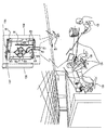
도 1에 도시된 바와 같이, 안테나(100)가 제공되어 있다. 안테나(100)는 실내형 안테나인 것이 바람직하고 특히 벽(102)에 장착되도록 구성되는 것이 바람직하다. 그러나, 안테나(100)는 대안으로, 안테나(100)의 동작 필요에 따라, 다양한 실내 및 실외 표면에 장착되도록 구성될 수 있다는 것을 이해할 수 있다. As shown in Fig. 1, an
확대도(104)에 가장 잘 볼 수 있는 바와 같이, 안테나(100)는 접지면(106)을 포함하고 있다. 광대역 다이폴 방사 소자(108)는 접지면(106) 위에 위치되는 것이 바람직하다. 광대역 다이폴 방사 소자(108)는 ±45° 경사의 편파를 갖는 이중 편파 신호를 전송하도록 동작하는 것이 바람직하다. 광대역 다이폴 방사 소자(108)는 그래서 광대역 이중 편파 다이폴 방사 소자(108)로 부를 수 있다. As best seen in the enlarged view (104), the antenna (100) includes a ground plane (106). The broadband
수평 편파 다이폴 방사 소자(114)는 제1 축(115)에 평행한 돌출부를 갖고 있고 이중 편파 다이폴 방사 소자(108)에 인접한 접지면(106) 위에 위치되는 것이 바람직하고, 이러한 제1 축(115)은 광대역 이중 편파 다이폴 방사 소자(108)를 교차하는 것이 바람직하다. 수직 편파 다이폴 방사 소자(116)는 제1 축(117)에 평행한 돌출부를 갖고 있고 이중 편파 다이폴 방사 소자(108)에 인접한 접지면(106)에 위치되는 것이 바람직하고, 이러한 제2 축(117)은 광대역 이중 편파 다이폴 방사 소자(108)를 교차하고 제1 축에 직교하는 것이 바람직하다. 여기에서, 예를 들어, 수평 및 수직 편파 다이폴 방사 소자(114, 116)는 각각 제1 축(115)과 제2 축(117)에 평행하게 위치되는 것이 도시되어 있다. The horizontal polarization dipole
안테나(100)의 동작에서, 이중 편파 다이폴 방사 소자(108)는 1700 - 2700 MHz의 고주파수 대역으로 방사하는 것이 바람직하고 수평 및 수직 편파 다이폴 방사 소자(114, 116)는 690 - 960 MHz의 저주파수 대역으로 방사하는 것이 바람직하다. 따라서, 안테나(100)는 ±45° 경사의 이중 편파, 수평 및 수직 편파 다이폴 방사 소자(108, 114 및 116)의 각각의 동시 동작에 의해, 고주파수 ±45° 경사 방사 무선 주파수(RF) 신호 및 저주파수 수직 및 수평 편파 RF 신호를 동시에 방사할 수 있는 이중 대역 이중 편파 안테나를 구성한다는 것을 이해할 수 있다. 이들의 상호 직교 편파로 인해, 수평 및 수직 편파 다이폴 방사 소자(114, 116)는 상관 제거되어, 안테나(100)가 특히 MIMO 적용에 적합하게 된다. In operation of the
수평 및 수직 편파 다이폴 방사 소자(114, 116)의 구성은 단지 예이고, 수평 및 수직 편파 다이폴 방사 소자(114, 116)가 이중 편파 다이폴 방사 소자(108)를 교차하는 직교 축(115, 117)에 평행한 각각의 돌출부를 갖도록 위치되어 있다면 다양한 다른 구성 및 배열의 수평 및 수직 편파 다이폴 방사 소자가 역시 가능하다는 것을 이해할 수 있다. The configuration of the horizontal and vertical polarization dipole radiating elements 114,116 is only an example and the horizontal and vertical polarized dipole radiating elements 114,116 are orthogonal axes 115,117 crossing the dual polarized dipole
도 1에 도시된 안테나(100)의 바람직한 실시예에서, 접지면(106)은 유전체 기판(120)이 위에 배치되는 것이 바람직하고 전기 접속되어 있는 접지 트레이(118)를 포함하는 것으로 도시되어 있다. 유전체 기판(120)은 급전망(도시되지 않음)을 일체화하여 형성하도록 구성되는 것이 바람직한 인쇄회로기판(PCB) 기재인 것이 바람직하다. In the preferred embodiment of the
접지 트레이(118) 및 유전체 기판(120)의 구조 및 배열은 본 발명의 바람직한 실시예의 특별한 특징부이고 안테나(100)의 동작에서 다수의 상당한 유익을 생성한다. The structure and arrangement of the
접지 트레이(118)의 크기, 형상 및 위치는 이중 편파 다이폴 방사 소자(108) 및, 수평 및 수직 편파 다이폴 방사 소자(114, 116)의 방사 패턴 및 격리를 이들의 각각의 고주파수 및 저주파수 동작 대역에서 제어하는 기능을 한다. 본 발명의 특별한 바람직한 실시에에서, 접지 트레이(118)는 그로부터 뻗은 다수의 연장 스트립(122)을 포함하고 있다. 연장 스트립(122)은 안테나(100)의 균일한 빔 패턴의 형상에 기여하고 저주파수 대역의 동작에서 격리를 향상시킨다. 저주파수 대역의 동작의 격리는 유전체 기판(120)과 접지 트레이(118) 사이의 전기 접속의 결과로서 더욱 향상된다. The size, shape, and location of the
이중 편파 다이폴 방사 소자(108) 및, 수평 및 수직 편파 다이폴 방사 소자(114, 116)에 대한 상술된 접지 트레이(118)의 배열에 의해 이중 편파 다이폴 방사 소자(108) 및, 수평 및 수직 편파 다이폴 방사 소자(114, 116)에 의한 균형 잡힌, 균일한, 지향성 및 다양한 편파의 방사 패턴을 형성할 수 있다. 이러한 방사 패턴에 의해 안테나(100)는 그림으로 표현된 RF 빔(124)에 의해 표시된 바와 같이, 벽 장착형 안테나로서 배치하기에 특히 적절할 수 있다. The dual polarized dipole
이중 편파 다이폴 방사 소자(108) 및, 수평 및 수직 편파 다이폴 방사 소자(114, 116)의 균형잡힌, 균일하고 잘 격리된 빔 패턴으로 인해, 안테나(100)는 높은 RF 데이터 처리율 및 최소의 페이딩 및 산란 효과로 사용자(126, 128, 130)와 같은 다수의 사용자를 도울 수 있다. 또한, 이중 편파 다이폴 방사 소자(108) 및, 수평 및 수직 편파 다이폴 방사 소자(114, 116)가 접지 트레이(118)에 의해 형성된 단일 플랫폼 위에 서로 근접하여 장착되어 있기 때문에, 안테나(100)는 종래의 MIMO 안테나에 비교하여 극히 소형이고 비교적 단순하고 제조 비용이 저렴하다. Due to the balanced, uniform and well-isolated beam pattern of the dual polarized
이중 편파 다이폴 방사 소자(108) 및, 수평 편파 다이폴 방사 소자(114)는 제2 동축 케이블(132)에 접속된 제1 포트에서 제1 편파를 갖는 RF 입력 신호를 수신하는 것이 바람직하고 이중 편파 다이폴 방사 소자(108) 및, 수직 편파 다이폴 방사 소자(116)는 제2 동축 케이블(134)에 접속된 제2 포트에서 제2 편파를 갖는 RF 입력 신호를 수신하는 것이 바람직하다. 이중 편파 다이폴 방사 소자(108) 및, 수평 및 수직 편파 다이폴 방사 소자(114, 116)가 급전되는 것이 바람직한 급전 배열의 다른 상세는 도 2a 내지 도 3를 참조하여 아래에 제시되어 있다. The dual polarized
안테나(100)는 옵션으로 미학적 기능 및 보호성 기능 모두를 갖는 커버(136)에 수용될 수 있다. 커버(136)는 안테나(100)의 바람직한 방사 패턴을 왜곡시키지 않는 임의의 적절한 재료로 형성될 수 있다. The
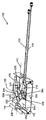
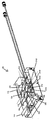
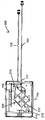
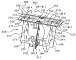
이제, 도 1에 도시된 타입의 안테나의 단순화된 제1 및 제2 사시도 및 평면도인 도 2a, 도 2b 및 도 2c; 및 도 1 내지 도 2c에 도시된 타입의 안테나에 사용된 방사 소자의 단순화된 확대도인 도 3에 대해 설명한다. 2A, 2B and 2C, which are simplified first and second perspective and plan views of an antenna of the type shown in Fig. 1; Fig. And Fig. 3, which is a simplified enlarged view of the radiating element used in the antenna of the type shown in Figs. 1 to 2C.
도 2a 내지 도 3에 도시된 바와 같이, 안테나(100)는 광대역 이중 편파 다이폴 방사 소자(108), 수평 편파 다이폴 방사 소자(114) 및 수직 편파 다이폴 방사 소자(116)를 포함하고 있다. 광대역 이중 편파 다이폴 방사 소자(108), 수평 편파 다이폴 방사 소자(114) 및 수직 편파 다이폴 방사 소자(116)는 접지 트레이(118) 위에 위치되고 제1 및 제2 동축 케이블(132, 134)에 의해 급전되는 것이 바람직하다.2A-3, the
도 2a 및 도 2b에서 가장 분명하게 볼 수 있는 바와 같이, 수평 편파 다이폴 방사 소자(114) 및 수직 편파 다이폴 방사 소자(116)는 그 사이의 간섭을 최소화하기 위해 상이한 급전 장치를 갖는 상이한 타입의 다이폴을 포함하는 것이 바람직하다. 그다음, 수평 편파 다이폴 방사 소자(114)는 함께 일체화된 마이크로스트립 급전선(204)을 갖는 다이폴 스템(stem)(202) 및 다이폴 암부(206)를 포함하는 것이 바람직하다. 수직 편파 다이폴 방사 소자(116)는 위에 형성된 마이크로스트립 급전선(210)을 포함하는 모놀리식 소자(208)로서 구현되는 것이 바람직하다. 2A and 2B, the horizontal polarization
마이크로스트립 급전선(204, 210)은 급전망(212)에 접속되어 급전되는 것이 바람직하다. 도 2c에 가장 잘 도시된 바와 같이, 급전망(212)은 제1 다이플렉서(214) 및 제2 다이플렉서(216)을 포함하는 것이 바람직하다. 제1 및 제2 다이플렉서(214, 216)는 안테나(100)의 급전 장치를 단순히 하기 위해 이중 편파 다이폴 방사 소자(108) 및, 수평 및 수직 편파 다이폴 방사 소자(114, 116)가 오직 2개의 포트에 의해 급전될 수 있도록 제1 및 제2 동축 케이블(132, 134)에 의해 전달된 신호를 분리하도록 동작하는 것이 바람직하다. 급전망(212)은 유전체 기판(120)의 하측에 형성되는 것이 바람직하다. 급전망(212)이 단지 이해를 위해서 도 2a 내지 도 2c에 도시된 것을 이해할 수 있다. It is preferable that the
도 3에 가장 잘 도시된 바와 같이, 이중 편파 다이폴 방사 소자(108)는 접지면(106)으로부터 오프셋된 방사 패치(220)의 4분체를 포함하는 것이 바람직하다. 도 1a 내지 도 3에 도시된 이중 편파 다이폴 방사 소자(108)의 실시예에서, 방사 패치(220)의 4분체는 제1, 제2, 제3 및 제4 정방형 패치(222, 224, 226, 228)를 포함하는 것으로 도시되어 있고, 제1 내지 제4 패치(222-228)는 다수의 전기 접속부(230)에 의해 상호접속된 것이 바람직하다. As best shown in FIG. 3, the dual polarized
이중 편파 다이폴 방사 소자(108)의 동작중에, 방사 패치(220)의 4분체는 이후에 설명되는 방식으로 제1 편파에서 제1 쌍의 다이폴로서 그리고 제2 편파에서 제2 쌍의 다이폴로서 동작하는 것이 바람직하다. During operation of the dual polarization
방사 패치(220)의 4분체는 다이폴 스템(234)의 상부에 배치되는 것이 바람직한 유전 플랫폼(232)에 의해 지지되는 것이 바람직하다. 그러나, 방사 패치(220)의 4분체가 대안으로 당업계에 알려진 다른 수단에 의해 다이폴 스템(234) 위에 배치될 수 있어서 유전 플랫폼(232)이 대안의 비도전성 구조에 의해 대체되거나 제거될 수 있는 것을 이해할 수 있다. Preferably, the quadrants of the
다이폴 스템(234)은 4개의 교차 상호 수직 립(rib)(240, 242, 244, 246)에 의해 형성되는 것이 바람직한 X 형상의 구성을 갖고 있고, 4개의 립(240, 242, 244, 246)의 각각은 압출 상부 스터브(stub)부(248, 250, 252, 254)를 각각 포함하는 것이 바람직하다. 도 3에 가장 잘 도시된 바와 같이, 압출 상부 스터브부(248, 250, 252, 254)는 방사 소자(108)가 조립된 상태일 때 유전 플랫폼(232)에 형성된 4개의 슬롯(256, 258, 260, 262) 속에 끼워지는 것이 바람직하다. The dipole stem 234 has an X-shaped configuration which is preferably formed by four crossed
유전 플랫폼(232)에 대한 다이폴 스템(234)의 상술된 배열은 단지 예일 뿐이고 다이폴 스템(234)는 대안으로, 당업자에 의해 용이하게 이해되는 바와 같이 다양한 다른 배열을 통해 유전 플랫폼(232)을 지지하도록 구성될 수 있다는 것을 이해할 수 있다.The above described arrangement of the
방사 패치(220)의 4분체는 다이폴 스템(234)과 일체화되는 것이 바람직한 급전 장치(264)에 의해 급전된다. 급전 장치(264)가 외부의 별개의 급전 장치로 형성되지 않고 다이폴 스템(234)과 일체화되는 것이 바람직하여 방사 소자(108)의 구조를 단순히하고 그 크기를 최소화하는 것이 본 발명의 바람직한 실시예의 특별한 특징이다. The quadrants of the
급전 장치(264)는 특히 립(240)의 제1 측부(272)에 형성된 제1 마이크로스트립 급전선(270) 및 립(240)의 제2 반대 측부(276)에 형성된 제1 발룬(274); 립(242)의 제1 측부(282)에 형성된 제2 마이크로스트립 급전선(280) 및 립(242)의 제2 반대 측부(286)에 형성된 제2 발룬(284); 립(244)의 제1 측부(292)에 형성된 제3 마이크로스트립 급전선(290) 및 립(244)의 제2 반대 측부(296)에 형성된 제3 발룬(294); 및 립(246)의 제1 측부(2102)에 형성된 제4 마이크로스트립 급전선(2100) 및 립(246)의 제2 반대 측부(2106)에 형성된 제4 발룬(2104)를 포함하는 것이 바람직하다. The
도 3의 립(240, 242, 244)의 경우에서 가장 잘 이해되는 바와 같이, 유전 플랫폼(232) 내의 슬롯(256, 258, 260, 262) 안에 립(240, 242, 244, 246)이 끼워지는 결과로서, 급전선(270, 280, 290, 2100), 및 발룬(274, 284, 294, 2104)은 방사 소자(108)가 조립된 상태에 있을 때, 각각 다수의 전기 접속부(230)와 전기 접촉하여서 방사 패치(222, 224, 226, 228)와 전기 접촉하는 것이 바람직하다. As best seen in the case of
급전선(270, 280, 290, 2100)이 방사 패치(222, 224, 226, 228)에 전기 접속하여서 정교하고, 단순하고 제조가 용이한 방사 소자(108)의 급전 장치를 얻을 수 있는 것이 본 발명의 바람직한 실시예의 특별한 특징이다. 그러나, 발룬(274, 284, 294, 2104)이 없다면, 이러한 전기 급전 장치에 의해 제한된 대역폭의 방사 소자(108)가 얻어질 것이다. 따라서, 발룬(274, 284, 294, 2104)을 제공하면 방사 소자(18)의 대역폭을 넓히는 장점이 있다. It is possible to obtain a feeding device of the radiating
도 2a 내지 도 3에 도시된 급전선(270, 280, 290, 2100) 및 발룬(274, 284, 294, 2104)의 특별한 구성은 단지 예이고 방사 소자(108)의 설계 및 동작 필요에 따라 당업자에 의해 용이하게 수정될 수 있다는 것을 이해할 수 있다. The particular configuration of the
급전선(270, 290)은 제1, 2:1 스플리터(2106)에 접속되어 있는 것이 바람직하고 급전선(280, 2100)은 제2, 2:1 스플리터(도시되지 않음)에 접속되어 있는 것이 바람직하다. It is preferable that the
방사 소자(108)의 동작중에, 급전선(270, 280)은 바람직하게는 2:1 스플리터에 결합된 동축 케이블(132, 134)에 의해 ±45°편파 신호를 수신하는 것이 바람직하다. 방사 패치(222, 224, 226, 228)를 가로지르는 ±45°편파 신호의 전류 분포는 도 3에 도시되어 있다. 도 3에서, 실선(2110)은 이중 ±45°편파 신호중 제1 신호를 위한 전류 분포를 나타내도록 사용되었고 점선(2112)은 이중 ±45°편파 신호중 제2 신호에 대한 전류 분포를 나타내도록 사용되었다. During operation of the radiating
도 3에 가장 잘 도시된 바와 같이, 실선(2110)에 의해 나타난 제1 편파에서, 방사 패치(222) 및 방사 패치(224)는 다이폴 A로 불리는 하나의 다이폴을 형성하고, 방사 패치(226) 및 방사 패치(228)은 다이폴 A와 평행하게 위치된 다이폴 B로 불리는 다른 다이폴을 형성한다. 마찬가지로, 점선(2112)에 의해 표시된 제2 편파에서, 방사 패치(222, 226)는 다이폴 C로 불리는 하나의 다이폴을 형성하고, 방사 패치(224, 228)는 다이폴 C와 평행하게 위치된 다이폴 D로 불리는 다른 다이폴을 형성한다. 따라서, 방사 패치(220)의 4분체는 제1 편파에서 제1 쌍의 다이폴, 즉, 다이폴 A 및 B로서 동작하고 제2 편파에서 제2 쌍의 다이폴, 즉, 다이폴 C 및 D로서 동작하고, 제1 및 제2 쌍의 다이폴의 각 다이폴은 방사 패치(220)의 4분체의 2개의 방사 패치를 포함한다. 3, the
도 2a 내지 도 3으로부터 알 수 있는 바와 같이, 각 편파에서 형성된 다이폴의 쌍의 각 다이폴을 포함하는 2개의 방사 패치 중 하나는 마이크로스트립 급전선(270, 280, 290, 2100)중 하나에 동작식 접속되어 있고 각 편파에서 형성된 다이폴의 쌍의 각 다이폴을 포함하는 2개의 방사 패치의 다른 패치는 발룬(274, 284, 294, 2104)중 하나에 동작식 접속되어 있다. As can be seen from Figs. 2A-3, one of the two radiation patches, including each dipole pair of dipoles formed in each polarization, is connected to one of the microstrip feed lines 270,280, 290, And another patch of two radiation patches comprising each dipole of a pair of dipoles formed in each polarization is operatively connected to one of the
용어 '동작식 접속된'은 각 편파에서 형성된 다이폴의 쌍의 각 다이폴에 대한 동작식 급전 장치와 일부만이 각 편파에서 각 방사 패치에 능동적으로 급전하는 다수의 급전선 및 발룬으로의 각 방사 패치의 수동적 전기 접속을 구별하기 위해 여기에 사용되었다는 것을 이해해야 한다. The term " operatively connected " refers to an operative feeding device for each dipole of a pair of dipoles formed in each polarization and only a portion of which is passively coupled to a plurality of feed lines and baluns actively feeding the respective radiation patch in each polarization It should be understood that it was used here to distinguish electrical connections.
각 편파에서 다이폴의 제1 및 제2 쌍에 급전하기 위한 급전 장치는 각 다이폴의 2개의 방사 소자중 다른 것에 전기 접속된 발룬 및 각 다이폴의 2개의 방사 소자중 하나에 전기 접속된, 예를 들어, 마이크로스트립 급전선으로서 여기에 구현된 급전선을 포함하는 것이 본 발명의 바람직한 실시예의 특별한 특징이다. 이러한 급전 장치의 결과로서, 다이폴의 제1 및 제2 쌍의 각 다이폴의 오직 하나의 방사 패치가 발룬에 의해 접지면에 접속되어 있다. 이것은 단일 다이폴을 형성하는 양측 패치가 보통 접지에 접속되어 있는 종래의 이중 편파 패치 안테나와 대조적이다. A feed device for feeding the first and second pairs of dipoles in each polarized wave is electrically connected to one of the two radiating elements of each dipole and the balun electrically connected to the other of the two radiating elements of each dipole, , It is a special feature of the preferred embodiment of the present invention that it includes a feed line embodied herein as a microstrip feed line. As a result of this feed device, only one radiation patch of each dipole of the first and second pairs of dipoles is connected to the ground plane by the balun. This is in contrast to conventional dual polarized patch antennas where both patches forming a single dipole are usually connected to ground.
따라서, 도 3에 가장 잘 도시된 바와 같이, 다이폴 A의 경우에, 방사 패치(222)는 급전선(270)에 동작식 접속되어 있고 방사 패치(224)는 발룬(274)에 동작식 접속되어 있고, 다이폴 B의 경우에, 방사 패치(226)는 급전선(290)에 동작식 접속되어 있고 방사 패치(228)는 발룬(294)에 동작식 접속되어 있다. 도 2b에 가장 잘 도시된 바와 같이, 다이폴 C의 경우에, 방사 패치(226)는 급전선(28)에 동작식 접속되어 있고 방사 패치(222)는 발룬(284)에 동작식 접속되어 있고, 다이폴 D의 경우에, 방사 패치(228)는 급전선(2100)에 동작식 접속되어 있고 방사 패치(224)는 발룬(2104)에 동작식 접속되어 있다. 3, the
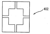
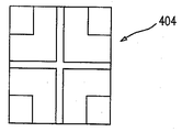
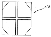
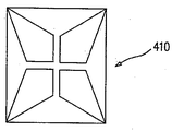
제1 내지 제4 정방형 패치(222, 224, 226, 228)의 각각은 λ/4 정도의 폭을 갖고 있는 것이 바람직하고, λ는 방사 소자(108)의 동작의 주파수에 상응하는 동작 파장이다. 도 1a 내지 도 3에 도시된 제1 내지 제4 정방형 패치(222, 224, 226, 228)의 정방형상은 단지 예이고 방사 패치(220)의 4분체의 각 방사 패치는 대안으로 λ/4 정도의 치수를 갖는 상이한 형상의 방사 패치를 포함할 수 있다는 것을 이해할 수 있다. 방사 패치(220)의 4분체의 대안의 바람직한 실시예는 도 4a에 도시된 반전된 L 형상의 패치(402)의 4분체, 도 4b에 도시된 L 형상의 패치(404)의 4분체, 도 4c에 도시된 반원 패치(406)의 4분체, 도 4d에 도시된 절두 삼각형 패치(408)의 4분체 및 도 4e에 도시된 4변형 패치(410)의 4분체를 포함한다. Each of the first through fourth
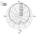
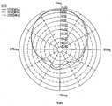
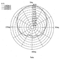
광대역 이중 편파 다이폴 방사 소자(108)의 성능 특성이 도 5a 내지 도 5d로부터 가장 잘 이해할 수 있는데, 도 5a는 제1 포트에서의 방사 소자(108)의 +45°에 대한 E면에서의 전체 이득을 도시하고 있고, 도 5b는 제1 포트에서의 방사 소자(108)의 +45° 편파에 대한 H면에서의 전체 이득을 도시하고 있고, 도 5c는 제2 포트에서의 방사 소자의 -45° 편파에 대한 E면에서의 전체 이득을 도시하고 있고, 도 5d는 제2 포트에서의 방사 소자(108)의 -45°편파에 대한 H면에서의 전체 이득을 도시하고 있다. The performance characteristics of the broadband dual polarization
도 5a 내지 도 5d에 도시된 바와 같이, 광대역 이중 편파 다이폴 방사 소자(108)는 그 편파의 양측에서 대략 동일한 E면 및 H면 방사 패턴을 가지고, 그 동작 환경에서 균형잡힌 서비스 범위(balanced coverage)를 제공하는 단지향성 공중선으로서 동작하는 것이 바람직하다. 소자(108)는 낮은 백 로브 방사를 가져서 유사한 주파수 범위에서 동작하는 같은 장소에 배치된 소자(108)중 다수의 소자 사이에서 간섭을 최소화하는 것이 더욱 바람직하다. 따라서, 소자(108)는 다수개의 안테나(100)가 단일 접지면을 따라 서로 근접하여 배열된 어레이에 포함되기에 적절하다. 5A-5D, the broadband dual polarized
본 발명은 아래에서 특별히 청구된 것에 제한되지 않는다는 것을 당업자는 이해할 것이다. 오히려 본 발명의 범위는 종래 기술에 있지 않고 도면을 참조하여 상기 설명을 읽을 때 당업자에 의해 이해되는 수정 및 변형은 물론 위에 기술된 특징의 다양한 조합 및 하위조합을 포함하고 있다. It will be understood by those skilled in the art that the present invention is not limited to what is specifically described below. Rather, the scope of the invention is not limited to the prior art and includes various combinations and subcombinations of the features described above, as well as modifications and variations as will be understood by those skilled in the art upon reading the foregoing description with reference to the drawings.
Claims (22)
접지면;
상기 접지면 위에 형성된 유전체 기판;
상기 유전체 기판 위에 위치된 광대역 이중 편파 다이폴 방사 소자;
상기 광대역 이중 편파 다이폴 방사 소자에 인접한 상기 유전체 기판 위에 위치되어 있고, 상기 광대역 이중 편파 다이폴 방사 소자를 교차하는 제1 축에 평행한 돌출부를 갖고 있는 수평 편파 다이폴 방사 소자;
상기 광대역 이중 편파 다이폴 방사 소자에 인접한 상기 유전체 기판 위에 위치되어 있고, 상기 광대역 이중 편파 다이폴 방사 소자를 교차하고 상기 제1 축에 직교하는 제2 축에 평행한 돌출부를 갖고 있는 수직 편파 다이폴 방사 소자; 및
상기 광대역 이중 편파 다이폴 방사 소자, 수평 편파 다이폴 방사 소자 및 수직 편파 다이폴 방사 소자에 급전하기 위한 급전망을 포함하는 것을 특징으로 하는 안테나. As an antenna,
Ground plane;
A dielectric substrate formed on the ground plane;
A broadband dual polarization dipole radiating element located on the dielectric substrate;
A horizontal polarization dipole radiating element positioned above the dielectric substrate adjacent to the broadband dual polarization dipole radiating element and having a projection parallel to a first axis intersecting the wideband dual polarized dipole radiating element;
A vertically polarized dipole radiating element located on the dielectric substrate adjacent to the broadband dual polarized dipole radiating element and having protrusions intersecting the broadband dual polarized dipole radiating element and parallel to a second axis orthogonal to the first axis; And
And a feedforward to feed the broadband dual polarized dipole radiating element, the horizontal polarized dipole radiating element and the vertical polarized dipole radiating element.
제1 편파에서 제1 쌍의 다이폴로서 동작하고 제2 편파에서 제2 쌍의 다이폴로서 동작하는 방사 패치의 4분체로서, 상기 제1 쌍의 다이폴 및 제2 쌍의 다이폴의 각 다이폴은 상기 방사 패치의 4분체 중 2개의 방사 패치를 포함하는 방사 패치의 4분체; 및
상기 제1 쌍의 다이폴 및 제2 쌍의 다이폴에 급전하기 위한 급전 장치로서, 상기 각 다이폴을 포함하는 상기 2개의 방사 패치 중 하나에 전기 접속된 급전선 및 상기 각 다이폴을 포함하는 상기 2개의 방사 패치 중 다른 하나에 전기 접속된 발룬을 포함하는 급전 장치를 포함하는 것을 특징으로 하는 안테나.The diplexer according to claim 1, wherein the broadband dual-
Wherein each dipole of the first pair of dipoles and the second pair of dipoles acts as a dipole of the radiation patch operating as a first pair of dipoles in the first polarization and acting as a second pair of dipoles in the second polarization, A quartz of a radiation patch comprising two of the quartz powders; And
A feeder electrically connected to one of said two radiation patches comprising said dipole and a second feeder wire electrically connected to said two radiation patches comprising said dipole and a second pair of dipoles, And a balun electrically connected to the other one of the baluns.
상기 제1 립의 제1 측부에 형성된 제1 마이크로스트립 급전선 및 상기 제1 립의 제2 반대 측부에 형성된 제1 발룬;
상기 제2 립의 제1 측부에 형성된 제2 마이크로스트립 급전선 및 상기 제2 립의 제2 반대 측부에 형성된 제2 발룬;
상기 제3 립의 제1 측부에 형성된 제3 마이크로스트립 급전선 및 상기 제3 립의 제2 반대 측부에 형성된 제3 발룬; 및
상기 제4 립의 제1 측부에 형성된 제4 마이크로스트립 급전선 및 상기 제4 립의 제2 반대 측부에 형성된 제4 발룬을 포함하는 것을 특징으로 하는 안테나.17. The power supply apparatus according to claim 16,
A first microstrip feed line formed on a first side of the first lip and a first balun formed on a second opposite side of the first lip;
A second microstrip feed line formed on a first side of the second lip and a second balun formed on a second opposite side of the second lip;
A third micro-strip feed line formed on a first side of the third lip and a third balun formed on a second opposite side of the third lip; And
A fourth microstrip feed line formed on a first side of the fourth lip, and a fourth balun formed on a second opposite side of the fourth lip.
제1 편파에서 제1 쌍의 다이폴로서 동작하고 제2 편파에서 제2 쌍의 다이폴로서 동작하는 방사 패치의 4분체로서, 상기 제1 쌍의 다이폴 및 제2 쌍의 다이폴의 각 다이폴은 상기 방사 패치의 4분체 중 2개의 방사 패치를 포함하는 방사 패치의 4분체; 및
상기 제1 쌍의 다이폴 및 제2 쌍의 다이폴에 급전하기 위한 급전 장치로서, 상기 각 다이폴을 포함하는 상기 2개의 방사 패치 중 하나에 전기 접속된 급전선 및 상기 각 다이폴을 포함하는 상기 2개의 방사 패치 중 다른 하나에 전기 접속된 발룬을 포함하는 급전 장치를 포함하는 것을 특징으로 하는 광대역 이중 편파 다이폴 방사 소자.As a broadband dual polarized dipole radiating element,
Wherein each dipole of the first pair of dipoles and the second pair of dipoles acts as a dipole of the radiation patch operating as a first pair of dipoles in the first polarization and acting as a second pair of dipoles in the second polarization, A quartz of a radiation patch comprising two of the quartz powders; And
A feeder electrically connected to one of the two radiation patches comprising each of the dipoles and a feeder line electrically connected to one of the two radiation patches comprising each of the dipoles, And a balun electrically connected to the other one of the baluns.
상기 제1 립의 제1 측부에 형성된 제1 마이크로스트립 급전선 및 상기 제1 립의 제2 반대 측부에 형성된 제1 발룬;
상기 제2 립의 제1 측부에 형성된 제2 마이크로스트립 급전선 및 상기 제2 립의 제2 반대 측부에 형성된 제2 발룬;
상기 제3 립의 제1 측부에 형성된 제3 마이크로스트립 급전선 및 상기 제3 립의 제2 반대 측부에 형성된 제3 발룬; 및
상기 제4 립의 제1 측부에 형성된 제4 마이크로스트립 급전선 및 상기 제4 립의 제2 반대 측부에 형성된 제4 발룬을 포함하는 것을 특징으로 하는 광대역 이중 편파 다이폴 방사 소자.22. The power supply apparatus according to claim 21,
A first microstrip feed line formed on a first side of the first lip and a first balun formed on a second opposite side of the first lip;
A second microstrip feed line formed on a first side of the second lip and a second balun formed on a second opposite side of the second lip;
A third micro-strip feed line formed on a first side of the third lip and a third balun formed on a second opposite side of the third lip; And
A fourth microstrip feed line formed on a first side of the fourth lip, and a fourth balun formed on a second opposite side of the fourth lip.
Applications Claiming Priority (5)
| Application Number | Priority Date | Filing Date | Title |
|---|---|---|---|
| US201261612442P | 2012-03-19 | 2012-03-19 | |
| US61/612,442 | 2012-03-19 | ||
| US201261746688P | 2012-12-28 | 2012-12-28 | |
| US61/746,688 | 2012-12-28 | ||
| PCT/IL2013/050266 WO2013140408A1 (en) | 2012-03-19 | 2013-03-19 | Multiple-input multiple-output antenna and broadband dipole radiating element therefore |
Publications (1)
| Publication Number | Publication Date |
|---|---|
| KR20140146118A true KR20140146118A (en) | 2014-12-24 |
Family
ID=49027260
Family Applications (1)
| Application Number | Title | Priority Date | Filing Date |
|---|---|---|---|
| KR20147029022A KR20140146118A (en) | 2012-03-19 | 2013-03-19 | Multiple-input multiple-output antenna and broadband dipole radiating element therefore |
Country Status (9)
| Country | Link |
|---|---|
| US (1) | US9461370B2 (en) |
| EP (1) | EP2828927A4 (en) |
| KR (1) | KR20140146118A (en) |
| CN (2) | CN104396085B (en) |
| CA (1) | CA2867669A1 (en) |
| IL (1) | IL234636A0 (en) |
| IN (1) | IN2014MN02070A (en) |
| RU (1) | RU2014141918A (en) |
| WO (1) | WO2013140408A1 (en) |
Families Citing this family (21)
| Publication number | Priority date | Publication date | Assignee | Title |
|---|---|---|---|---|
| US9461370B2 (en) | 2012-03-19 | 2016-10-04 | Galtronics Corporation, Ltd. | Multiple-input multiple-output antenna and broadband dipole radiating element therefore |
| US9343816B2 (en) | 2013-04-09 | 2016-05-17 | Raytheon Company | Array antenna and related techniques |
| TWI539657B (en) * | 2013-10-23 | 2016-06-21 | 宏碁股份有限公司 | Wearable communication device |
| US9437929B2 (en) * | 2014-01-15 | 2016-09-06 | Raytheon Company | Dual polarized array antenna with modular multi-balun board and associated methods |
| JP2016127481A (en) * | 2015-01-06 | 2016-07-11 | 株式会社東芝 | Polarization shared antenna |
| US10505259B2 (en) | 2015-08-18 | 2019-12-10 | Css Antenna, Llc (A Jma Company) | Multi-element telecommunications antenna |
| US20170062940A1 (en) * | 2015-08-28 | 2017-03-02 | Amphenol Corporation | Compact wideband dual polarized dipole |
| US10770803B2 (en) * | 2017-05-03 | 2020-09-08 | Commscope Technologies Llc | Multi-band base station antennas having crossed-dipole radiating elements with generally oval or rectangularly shaped dipole arms and/or common mode resonance reduction filters |
| CA3067947A1 (en) | 2017-07-05 | 2019-01-10 | Commscope Technologies Llc | Base station antennas having radiating elements with sheet metal-on dielectric dipole radiators and related radiating elements |
| US10424847B2 (en) | 2017-09-08 | 2019-09-24 | Raytheon Company | Wideband dual-polarized current loop antenna element |
| CN111492538B (en) * | 2017-10-04 | 2023-12-08 | 约翰梅扎林加瓜联合有限责任公司D/B/A Jma无线 | Integrated filter radiator for multi-band antenna |
| US10644389B1 (en) * | 2018-10-31 | 2020-05-05 | Nanning Fugui Precision Industrial Co., Ltd. | Double-frequency antenna structure with high isolation |
| CN109411872A (en) * | 2018-12-08 | 2019-03-01 | 佛山市盛夫通信设备有限公司 | Minimize dual polarization wall aerial |
| CN111293418A (en) | 2018-12-10 | 2020-06-16 | 康普技术有限责任公司 | Radiator assembly for base station antenna and base station antenna |
| CN109980329B (en) * | 2019-03-12 | 2023-12-26 | 广州司南技术有限公司 | Broadband dual polarized antenna |
| KR102529052B1 (en) * | 2019-06-12 | 2023-05-03 | 삼성전기주식회사 | Antenna apparatus |
| US11688947B2 (en) | 2019-06-28 | 2023-06-27 | RLSmith Holdings LLC | Radio frequency connectors, omni-directional WiFi antennas, omni-directional dual antennas for universal mobile telecommunications service, and related devices, systems, methods, and assemblies |
| CN113036400A (en) * | 2019-12-24 | 2021-06-25 | 康普技术有限责任公司 | Radiating element, antenna assembly and base station antenna |
| CN112072287B (en) * | 2020-09-03 | 2022-09-27 | 武汉凡谷电子技术股份有限公司 | Dual-polarized antenna module |
| US11245205B1 (en) | 2020-09-10 | 2022-02-08 | Integrity Microwave, LLC | Mobile multi-frequency RF antenna array with elevated GPS devices, systems, and methods |
| CN117650361B (en) * | 2023-10-30 | 2024-05-31 | 广东工业大学 | Broadband low-profile small circularly polarized antenna and wireless communication device |
Family Cites Families (21)
| Publication number | Priority date | Publication date | Assignee | Title |
|---|---|---|---|---|
| US4814777A (en) | 1987-07-31 | 1989-03-21 | Raytheon Company | Dual-polarization, omni-directional antenna system |
| US5926137A (en) | 1997-06-30 | 1999-07-20 | Virginia Tech Intellectual Properties | Foursquare antenna radiating element |
| US6072439A (en) | 1998-01-15 | 2000-06-06 | Andrew Corporation | Base station antenna for dual polarization |
| DE19823749C2 (en) * | 1998-05-27 | 2002-07-11 | Kathrein Werke Kg | Dual polarized multi-range antenna |
| WO2001067545A1 (en) | 2000-03-07 | 2001-09-13 | Galtronics Usa, Inc. | Antenna connector |
| US7050005B2 (en) * | 2002-12-05 | 2006-05-23 | Kathrein-Werke Kg | Two-dimensional antenna array |
| US6977616B2 (en) | 2003-09-01 | 2005-12-20 | Alps Electric Co., Ltd. | Dual-band antenna having small size and low-height |
| WO2005079158A2 (en) | 2004-02-23 | 2005-09-01 | Galtronics Ltd. | Conical beam cross-slot antenna |
| DE102004025904B4 (en) * | 2004-05-27 | 2007-04-05 | Kathrein-Werke Kg | antenna |
| DE202005015708U1 (en) * | 2005-10-06 | 2005-12-29 | Kathrein-Werke Kg | Dual-polarized broadside dipole array, e.g. for crossed antennas, has a dual-polarized radiator with polarizing planes and a structure like a dipole square |
| US7843389B2 (en) | 2006-03-10 | 2010-11-30 | City University Of Hong Kong | Complementary wideband antenna |
| US7629939B2 (en) * | 2006-03-30 | 2009-12-08 | Powerwave Technologies, Inc. | Broadband dual polarized base station antenna |
| KR100853670B1 (en) * | 2006-04-03 | 2008-08-25 | (주)에이스안테나 | Dual Polarization Broadband Antenna having with single pattern |
| US7688271B2 (en) * | 2006-04-18 | 2010-03-30 | Andrew Llc | Dipole antenna |
| KR100883408B1 (en) * | 2006-09-11 | 2009-03-03 | 주식회사 케이엠더블유 | Dual-band dual-polarized base station antenna for mobile communication |
| US20110175782A1 (en) | 2008-09-22 | 2011-07-21 | Kmw Inc. | Dual-band dual-polarized antenna of base station for mobile communication |
| CN101465475A (en) * | 2009-01-12 | 2009-06-24 | 京信通信系统(中国)有限公司 | Dual polarization radiating element and plane vibrator thereof |
| WO2011154954A2 (en) | 2010-06-09 | 2011-12-15 | Galtronics Corporation Ltd. | Directive antenna with isolation feature |
| CN201797035U (en) * | 2010-07-20 | 2011-04-13 | 江苏捷士通科技股份有限公司 | Dual-polarized base station antenna die-casting radiation unit |
| CN201820883U (en) * | 2010-09-25 | 2011-05-04 | 广东通宇通讯设备有限公司 | High-performance broadband bipolarized radiation element and antenna |
| US9461370B2 (en) * | 2012-03-19 | 2016-10-04 | Galtronics Corporation, Ltd. | Multiple-input multiple-output antenna and broadband dipole radiating element therefore |
-
2013
- 2013-03-19 US US14/386,243 patent/US9461370B2/en active Active
- 2013-03-19 IN IN2070MUN2014 patent/IN2014MN02070A/en unknown
- 2013-03-19 CN CN201380021337.4A patent/CN104396085B/en not_active Expired - Fee Related
- 2013-03-19 CA CA 2867669 patent/CA2867669A1/en not_active Withdrawn
- 2013-03-19 KR KR20147029022A patent/KR20140146118A/en not_active Application Discontinuation
- 2013-03-19 CN CN2013201261847U patent/CN203166098U/en not_active Withdrawn - After Issue
- 2013-03-19 EP EP13764067.8A patent/EP2828927A4/en not_active Withdrawn
- 2013-03-19 RU RU2014141918A patent/RU2014141918A/en not_active Application Discontinuation
- 2013-03-19 WO PCT/IL2013/050266 patent/WO2013140408A1/en active Application Filing
-
2014
- 2014-09-14 IL IL234636A patent/IL234636A0/en unknown
Also Published As
| Publication number | Publication date |
|---|---|
| IL234636A0 (en) | 2014-11-30 |
| RU2014141918A (en) | 2016-05-10 |
| US9461370B2 (en) | 2016-10-04 |
| EP2828927A1 (en) | 2015-01-28 |
| CN104396085B (en) | 2017-04-12 |
| IN2014MN02070A (en) | 2015-08-21 |
| CN104396085A (en) | 2015-03-04 |
| CA2867669A1 (en) | 2013-09-26 |
| CN203166098U (en) | 2013-08-28 |
| WO2013140408A1 (en) | 2013-09-26 |
| US20150116174A1 (en) | 2015-04-30 |
| EP2828927A4 (en) | 2015-11-25 |
Similar Documents
| Publication | Publication Date | Title |
|---|---|---|
| KR20140146118A (en) | Multiple-input multiple-output antenna and broadband dipole radiating element therefore | |
| US10854994B2 (en) | Broadband phased array antenna system with hybrid radiating elements | |
| US20170062940A1 (en) | Compact wideband dual polarized dipole | |
| US9083086B2 (en) | High gain and wideband complementary antenna | |
| KR101872460B1 (en) | Broadband dual-polarized antenna | |
| EP2908380B1 (en) | Wideband dual-polarized patch antenna array and methods useful in conjunction therewith | |
| Mak et al. | A shorted bowtie patch antenna with a cross dipole for dual polarization | |
| US9401545B2 (en) | Multi polarization conformal channel monopole antenna | |
| KR102172187B1 (en) | Omni-directional antenna for mobile communication service | |
| EP2950385B1 (en) | Multiband antenna | |
| US9793607B2 (en) | Antenna with quarter wave patch element, U-Slot, and slotted shorting wall | |
| US7710327B2 (en) | Multi band indoor antenna | |
| US20140240188A1 (en) | Dual-polarized dipole antenna and cruciform coupling element therefore | |
| US20130328733A1 (en) | Waveguide or slot radiator for wide e-plane radiation pattern beamwidth with additional structures for dual polarized operation and beamwidth control | |
| EP2937933B1 (en) | Low-profile wideband antenna element and antenna | |
| US20140062824A1 (en) | Circular polarization antenna and directional antenna array having the same | |
| EP2913892A1 (en) | An antenna, a multiple antenna array and a method of radiating a radio-frequency signal | |
| CN109509970A (en) | Dual polarized antenna | |
| Huang et al. | A wide-band dual-polarized frequency-reconfigurable slot-ring antenna element using a diagonal feeding method for array design | |
| CN111162380A (en) | Dual-polarized broadband high-gain wide-beam antenna | |
| US11670859B1 (en) | Tri-band dual-polarized omnidirectional antenna | |
| TWI451632B (en) | High gain loop array antenna system and electronic device | |
| Yang et al. | Dual-polarized multi-layer patch antenna with pattern reconfigurable characteristic | |
| CN209544596U (en) | Dual polarized antenna | |
| TW201721965A (en) | Beam-width adjustable multi-input multi-output antenna device and assembly device thereof capable of easily adjusting the beam width of an antenna by setting a control switch |
Legal Events
| Date | Code | Title | Description |
|---|---|---|---|
| WITN | Application deemed withdrawn, e.g. because no request for examination was filed or no examination fee was paid |