KR20140136991A - Wireless power transfer device and method of manufacture - Google Patents
Wireless power transfer device and method of manufacture Download PDFInfo
- Publication number
- KR20140136991A KR20140136991A KR1020147028732A KR20147028732A KR20140136991A KR 20140136991 A KR20140136991 A KR 20140136991A KR 1020147028732 A KR1020147028732 A KR 1020147028732A KR 20147028732 A KR20147028732 A KR 20147028732A KR 20140136991 A KR20140136991 A KR 20140136991A
- Authority
- KR
- South Korea
- Prior art keywords
- casing
- fluid medium
- cured
- wireless power
- medium
- Prior art date
Links
Images


Classifications
-
- H—ELECTRICITY
- H02—GENERATION; CONVERSION OR DISTRIBUTION OF ELECTRIC POWER
- H02J—CIRCUIT ARRANGEMENTS OR SYSTEMS FOR SUPPLYING OR DISTRIBUTING ELECTRIC POWER; SYSTEMS FOR STORING ELECTRIC ENERGY
- H02J50/00—Circuit arrangements or systems for wireless supply or distribution of electric power
- H02J50/10—Circuit arrangements or systems for wireless supply or distribution of electric power using inductive coupling
- H02J50/12—Circuit arrangements or systems for wireless supply or distribution of electric power using inductive coupling of the resonant type
-
- H—ELECTRICITY
- H01—ELECTRIC ELEMENTS
- H01F—MAGNETS; INDUCTANCES; TRANSFORMERS; SELECTION OF MATERIALS FOR THEIR MAGNETIC PROPERTIES
- H01F38/00—Adaptations of transformers or inductances for specific applications or functions
- H01F38/14—Inductive couplings
-
- B—PERFORMING OPERATIONS; TRANSPORTING
- B60—VEHICLES IN GENERAL
- B60L—PROPULSION OF ELECTRICALLY-PROPELLED VEHICLES; SUPPLYING ELECTRIC POWER FOR AUXILIARY EQUIPMENT OF ELECTRICALLY-PROPELLED VEHICLES; ELECTRODYNAMIC BRAKE SYSTEMS FOR VEHICLES IN GENERAL; MAGNETIC SUSPENSION OR LEVITATION FOR VEHICLES; MONITORING OPERATING VARIABLES OF ELECTRICALLY-PROPELLED VEHICLES; ELECTRIC SAFETY DEVICES FOR ELECTRICALLY-PROPELLED VEHICLES
- B60L53/00—Methods of charging batteries, specially adapted for electric vehicles; Charging stations or on-board charging equipment therefor; Exchange of energy storage elements in electric vehicles
- B60L53/10—Methods of charging batteries, specially adapted for electric vehicles; Charging stations or on-board charging equipment therefor; Exchange of energy storage elements in electric vehicles characterised by the energy transfer between the charging station and the vehicle
- B60L53/12—Inductive energy transfer
- B60L53/122—Circuits or methods for driving the primary coil, e.g. supplying electric power to the coil
-
- B—PERFORMING OPERATIONS; TRANSPORTING
- B60—VEHICLES IN GENERAL
- B60L—PROPULSION OF ELECTRICALLY-PROPELLED VEHICLES; SUPPLYING ELECTRIC POWER FOR AUXILIARY EQUIPMENT OF ELECTRICALLY-PROPELLED VEHICLES; ELECTRODYNAMIC BRAKE SYSTEMS FOR VEHICLES IN GENERAL; MAGNETIC SUSPENSION OR LEVITATION FOR VEHICLES; MONITORING OPERATING VARIABLES OF ELECTRICALLY-PROPELLED VEHICLES; ELECTRIC SAFETY DEVICES FOR ELECTRICALLY-PROPELLED VEHICLES
- B60L53/00—Methods of charging batteries, specially adapted for electric vehicles; Charging stations or on-board charging equipment therefor; Exchange of energy storage elements in electric vehicles
- B60L53/10—Methods of charging batteries, specially adapted for electric vehicles; Charging stations or on-board charging equipment therefor; Exchange of energy storage elements in electric vehicles characterised by the energy transfer between the charging station and the vehicle
- B60L53/12—Inductive energy transfer
- B60L53/126—Methods for pairing a vehicle and a charging station, e.g. establishing a one-to-one relation between a wireless power transmitter and a wireless power receiver
-
- H—ELECTRICITY
- H01—ELECTRIC ELEMENTS
- H01F—MAGNETS; INDUCTANCES; TRANSFORMERS; SELECTION OF MATERIALS FOR THEIR MAGNETIC PROPERTIES
- H01F27/00—Details of transformers or inductances, in general
- H01F27/02—Casings
- H01F27/022—Encapsulation
-
- H—ELECTRICITY
- H01—ELECTRIC ELEMENTS
- H01F—MAGNETS; INDUCTANCES; TRANSFORMERS; SELECTION OF MATERIALS FOR THEIR MAGNETIC PROPERTIES
- H01F41/00—Apparatus or processes specially adapted for manufacturing or assembling magnets, inductances or transformers; Apparatus or processes specially adapted for manufacturing materials characterised by their magnetic properties
- H01F41/005—Impregnating or encapsulating
-
- H—ELECTRICITY
- H02—GENERATION; CONVERSION OR DISTRIBUTION OF ELECTRIC POWER
- H02J—CIRCUIT ARRANGEMENTS OR SYSTEMS FOR SUPPLYING OR DISTRIBUTING ELECTRIC POWER; SYSTEMS FOR STORING ELECTRIC ENERGY
- H02J7/00—Circuit arrangements for charging or depolarising batteries or for supplying loads from batteries
- H02J7/0042—Circuit arrangements for charging or depolarising batteries or for supplying loads from batteries characterised by the mechanical construction
-
- Y—GENERAL TAGGING OF NEW TECHNOLOGICAL DEVELOPMENTS; GENERAL TAGGING OF CROSS-SECTIONAL TECHNOLOGIES SPANNING OVER SEVERAL SECTIONS OF THE IPC; TECHNICAL SUBJECTS COVERED BY FORMER USPC CROSS-REFERENCE ART COLLECTIONS [XRACs] AND DIGESTS
- Y02—TECHNOLOGIES OR APPLICATIONS FOR MITIGATION OR ADAPTATION AGAINST CLIMATE CHANGE
- Y02T—CLIMATE CHANGE MITIGATION TECHNOLOGIES RELATED TO TRANSPORTATION
- Y02T10/00—Road transport of goods or passengers
- Y02T10/60—Other road transportation technologies with climate change mitigation effect
- Y02T10/70—Energy storage systems for electromobility, e.g. batteries
-
- Y—GENERAL TAGGING OF NEW TECHNOLOGICAL DEVELOPMENTS; GENERAL TAGGING OF CROSS-SECTIONAL TECHNOLOGIES SPANNING OVER SEVERAL SECTIONS OF THE IPC; TECHNICAL SUBJECTS COVERED BY FORMER USPC CROSS-REFERENCE ART COLLECTIONS [XRACs] AND DIGESTS
- Y02—TECHNOLOGIES OR APPLICATIONS FOR MITIGATION OR ADAPTATION AGAINST CLIMATE CHANGE
- Y02T—CLIMATE CHANGE MITIGATION TECHNOLOGIES RELATED TO TRANSPORTATION
- Y02T10/00—Road transport of goods or passengers
- Y02T10/60—Other road transportation technologies with climate change mitigation effect
- Y02T10/7072—Electromobility specific charging systems or methods for batteries, ultracapacitors, supercapacitors or double-layer capacitors
-
- Y—GENERAL TAGGING OF NEW TECHNOLOGICAL DEVELOPMENTS; GENERAL TAGGING OF CROSS-SECTIONAL TECHNOLOGIES SPANNING OVER SEVERAL SECTIONS OF THE IPC; TECHNICAL SUBJECTS COVERED BY FORMER USPC CROSS-REFERENCE ART COLLECTIONS [XRACs] AND DIGESTS
- Y02—TECHNOLOGIES OR APPLICATIONS FOR MITIGATION OR ADAPTATION AGAINST CLIMATE CHANGE
- Y02T—CLIMATE CHANGE MITIGATION TECHNOLOGIES RELATED TO TRANSPORTATION
- Y02T90/00—Enabling technologies or technologies with a potential or indirect contribution to GHG emissions mitigation
- Y02T90/10—Technologies relating to charging of electric vehicles
- Y02T90/12—Electric charging stations
-
- Y—GENERAL TAGGING OF NEW TECHNOLOGICAL DEVELOPMENTS; GENERAL TAGGING OF CROSS-SECTIONAL TECHNOLOGIES SPANNING OVER SEVERAL SECTIONS OF THE IPC; TECHNICAL SUBJECTS COVERED BY FORMER USPC CROSS-REFERENCE ART COLLECTIONS [XRACs] AND DIGESTS
- Y02—TECHNOLOGIES OR APPLICATIONS FOR MITIGATION OR ADAPTATION AGAINST CLIMATE CHANGE
- Y02T—CLIMATE CHANGE MITIGATION TECHNOLOGIES RELATED TO TRANSPORTATION
- Y02T90/00—Enabling technologies or technologies with a potential or indirect contribution to GHG emissions mitigation
- Y02T90/10—Technologies relating to charging of electric vehicles
- Y02T90/14—Plug-in electric vehicles
-
- Y—GENERAL TAGGING OF NEW TECHNOLOGICAL DEVELOPMENTS; GENERAL TAGGING OF CROSS-SECTIONAL TECHNOLOGIES SPANNING OVER SEVERAL SECTIONS OF THE IPC; TECHNICAL SUBJECTS COVERED BY FORMER USPC CROSS-REFERENCE ART COLLECTIONS [XRACs] AND DIGESTS
- Y10—TECHNICAL SUBJECTS COVERED BY FORMER USPC
- Y10T—TECHNICAL SUBJECTS COVERED BY FORMER US CLASSIFICATION
- Y10T29/00—Metal working
- Y10T29/49—Method of mechanical manufacture
- Y10T29/49002—Electrical device making
- Y10T29/4902—Electromagnet, transformer or inductor
Landscapes
- Engineering & Computer Science (AREA)
- Power Engineering (AREA)
- Manufacturing & Machinery (AREA)
- Transportation (AREA)
- Mechanical Engineering (AREA)
- Computer Networks & Wireless Communication (AREA)
- Electric Propulsion And Braking For Vehicles (AREA)
- Charge And Discharge Circuits For Batteries Or The Like (AREA)
- Current-Collector Devices For Electrically Propelled Vehicles (AREA)
- Insulating Of Coils (AREA)
- Manufacturing Cores, Coils, And Magnets (AREA)
Abstract
무선 전력 전송, 특히 전기 운송수단들과 같은 원격 시스템들로의 무선 전력 전송을 위한 방법들 및 장치들이 개시된다. 일 양태에서, 적어도 하나의 컴포넌트를 수용하는 케이싱을 포함하는 무선 전력 전송 디바이스는, 경화된 제 1의 유동성 매체를 포함하는 케이싱의 제 1의 부분, 및 제 1의 경화된 유동성 매체의 밀도와는 상이한 밀도를 갖는 제 2의 경화된 유동성 매체를 포함하는 케이싱의 제 2의 부분을 구비한다. 케이싱은 로케이팅 부분을 포함할 수 있는데, 로케이팅 부분은 케이싱 내에서 경화된 유동성 매체와 접촉하게 된다. 다른 양태에서, 무선 전력 전송 디바이스 제조 방법이 제공된다. 제조 동안, 적어도 하나의 컴포넌트 및 경화가능한 유동성 매체가 케이싱에 도입되는 동안 소망의 형상을 유지하도록 디바이스의 케이싱은 부하를 받을 수도 있다.Methods and apparatus for wireless power transmission, particularly wireless power transmission to remote systems, such as electric vehicles, are disclosed. In one aspect, a wireless power transmission device comprising a casing that accommodates at least one component includes a first portion of the casing including the first fluidized media that is hardened, and a second portion of the first hardened fluided media, And a second portion of the casing comprising a second hardened fluid medium having a different density. The casing may include a locating portion, wherein the locating portion is brought into contact with the cured fluid medium in the casing. In another aspect, a method of manufacturing a wireless power transmission device is provided. During manufacture, the casing of the device may be loaded to maintain the desired shape while at least one component and the curable fluid medium are introduced into the casing.

Description
본 기술 분야는 일반적으로 무선 전력 전송, 특히 배터리에 의해 전력을 공급받는 운송수단들과 같은 원격 시스템들로의 무선 전력 전송에 관련된 디바이스들, 시스템들, 및 방법들에 관한 것이다. 특히, 그 분야는 무선 전력 전송 시스템들에서 사용되는 무선 전력 전송 디바이스들의 제조를 위한 배치들에 관련된다.The field generally relates to devices, systems, and methods related to wireless power transmission, particularly wireless power transmission to remote systems such as battery-powered vehicles. In particular, the field relates to arrangements for manufacturing wireless power transmission devices used in wireless power transmission systems.
배터리와 같은 에너지 저장 디바이스로부터 수신된 전기로부터 도출된 운동력 (locomotion power) 을 포함하는 원격 시스템들, 예컨대 운송수단들이 도입되었다. 예를 들면, 하이브리드 전기 운송수단들은, 운송수단들을 충전하기 위해 운송수단 브레이킹 및 모터들로부터의 전력을 사용하는 온보드 충전기들을 포함한다. 전적으로 전기차인 운송수단들은 배터리들을 충전하기 위한 전기를 다른 소스들로부터 일반적으로 수신한다. 배터리 전기 운송수단들 (전기 운송수단들) 은 어떤 타입의 유선의 교류 (AC) 예컨대 가정 또는 상용 AC 공급 소스들을 통해 충전되도록 종종 제안된다. 유선의 충전 접속부들은, 전원 (power supply) 에 물리적으로 연결되는 케이블들 또는 유사한 커넥터들을 필요로 한다. 케이블들 및 유사한 커넥터들은 때때로 불편하거나 다루기 힘들고 다른 단점들을 갖는다.Remote systems have been introduced, including locomotion power derived from electricity received from an energy storage device such as a battery, such as vehicles. For example, hybrid electric vehicles include onboard chargers that use power from the vehicles and braking the vehicle to charge the vehicles. Transportation vehicles, which are purely electric cars, generally receive electricity from other sources to charge batteries. Battery electric vehicles (electric vehicles) are often proposed to be charged through some type of wireline alternating current (AC), e.g., home or commercial AC supply sources. Wired charging connections require cables or similar connectors that are physically connected to a power supply. Cables and similar connectors are sometimes inconvenient, unwieldy, and have other disadvantages.
전기 운송수단들을 충전하기 위해 사용될 전력을 자유 공간에서 (예를 들면, 무선 필드를 통해) 전송할 수 있는 무선 충전 시스템들은, 유선의 충전 솔루션들의 단점들의 일부를 극복할 수도 있다. 이와 같이, 전기 운송수단들을 충전하기 위한 전력을 효율적으로 그리고 안전하게 전송하는 무선 충전 시스템들 및 방법들이 바람직하다.Wireless charging systems capable of transmitting power to be used for charging electric vehicles in free space (e.g., via a wireless field) may overcome some of the shortcomings of wired charging solutions. Thus, wireless charging systems and methods for efficiently and securely transferring power for charging electric vehicles are desirable.
무선 전력 전송 시스템들은 베이스와 픽업 전력 디바이스들 사이에서 전력을 전송하기 위해 유도 전력 전송 (inductive power transfer; IPT) 을 활용할 수도 있다. 운송수단 사용의 상황에서, 디바이스들은 지상에 위치될 수도 있고 따라서 충격력 및 압축력의 관점 그리고 또한 엘리먼트들, 특히 물에 대한 노출의 관점에서 가혹한 조건들에 노출될 수도 있다. 디바이스들의 보호는, 기계적 강도를 향상시키기 위해 디바이스의 구축시 두꺼운 차폐물을 사용하거나, 또는 베이스 디바이스를 지중에 매입하는 것에 의해 달성될 수도 있다. 그러나, 심미적 매력과 장착의 용이성 둘 다의 목적들을 위해 디바이스의 물리적 풋프린트를 감소시키는 것이 일반적으로 바람직하다. 전력 전송의 영향을 감소시키기 위해 베이스와 픽업 디바이스들 사이의 차폐의 정도를 최소화하는 것이 또한 바람직하다. 또한, 디바이스들, 특히 운송수단들에 장착되는 것들의 무게를 줄이는 것이 바람직할 수 있다.Wireless power transmission systems may utilize inductive power transfer (IPT) to transfer power between the base and the pickup power devices. In the context of vehicle use, the devices may be located on the ground and thus may be exposed to harsh conditions in terms of impact and compressive forces and also in terms of exposure to elements, particularly water. The protection of the devices may be achieved by using thicker shields in building the device to enhance the mechanical strength, or by embedding the base device in the ground. However, it is generally desirable to reduce the physical footprint of the device for both aesthetic appeal and ease of mounting. It is also desirable to minimize the degree of shielding between the base and the pick-up devices to reduce the impact of power transmission. It may also be desirable to reduce the weight of the devices, especially those mounted on vehicles.
개요summary
첨부된 청구항들의 범위 내에 있는 시스템들, 방법들, 및 디바이스들 각각은 상기 목적들 중 적어도 하나를 해결하도록 의도된 여러 양태들은 가지는데, 어떤 단일의 양태도 본원에서 설명된 바람직한 속성들에 대해 단독으로 책임지지 않는다. 첨부된 청구항들의 범위를 벗어나지 않으면서, 몇몇 두드러진 특징들이 본원에서 설명된다.Each of the systems, methods, and devices within the scope of the appended claims has several aspects that are intended to solve at least one of the above purposes, in which any single aspect is exclusive of the preferred attributes . Without departing from the scope of the appended claims, several salient features are described herein.
본 명세서에서 설명되는 본질의 하나 이상의 구현예들의 상세들은, 첨부된 도면들 및 하기의 상세한 설명에서 설명된다. 다른 특징들, 양태들, 및 이점들은 상세한 설명, 도면들, 및 특허청구범위로부터 명확해질 것이다. 하기의 도면들에서 상대적인 크기들은 일정한 축척으로 그려지지 않을 수도 있음을 주목해야 한다.The details of one or more embodiments of the essence described herein are set forth in the accompanying drawings and the description below. Other features, aspects, and advantages will be apparent from the description, drawings, and claims. It should be noted that the relative sizes in the following figures may not be drawn to a certain scale.
본 개시의 일 양태는 무선 전력 전송 디바이스에 관한 것이다. 몇몇 실시형태들의 디바이스는, 예를 들면, 케이싱, 케이싱 내에 수용되어 전력을 무선으로 수신하고 송신하도록 구성된 코일, 및 상기 코일의 적어도 일부를 둘러싸는 케이싱의 제 1의 부분에 포함되는 경화된 제 1의 유동성 매체를 포함한다. 몇몇 실시형태들에서, 케이싱의 제 2의 부분은 제 1의 경화된 유동성 매체와는 상이한 밀도를 갖는 경화된 제 2의 유동성 매체를 포함한다. 몇몇 실시형태들에서, 디바이스는 자기적으로 침투성인 부재를 더 포함한다. 자기적으로 침투성인 부재의 적어도 일부는 경화된 제 2의 유동성 매체 내에 유지된다. 몇몇 실시형태들에서, 케이싱은 경화된 제 1의 유동성 매체와 접촉하는 로케이팅 부분을 포함한다. 몇몇 이러한 실시형태들에서, 로케이팅 부분은 언더컷팅 부분이다. 다른 실시형태들에서, 로케이팅 부분은 케이싱에서의 어퍼쳐이다. 또 다른 실시형태들에서, 로케이팅 부분은 케이싱에서의 돌출부이다. 몇몇 실시형태들의 케이싱은 실질적으로 화확적으로 내성의 재료로 이루어진다. 몇몇 실시형태들에서, 케이싱은 폴리에틸렌으로 이루어진다.One aspect of the disclosure is directed to a wireless power transmission device. A device of some embodiments includes a casing, a coil housed in the casing and configured to receive and transmit power wirelessly, and a plurality of coils arranged in a first portion of the casing surrounding at least a portion of the coil, Of the fluid medium. In some embodiments, the second portion of the casing comprises a second cured fluid medium having a density different from the first cured fluid medium. In some embodiments, the device further comprises a magnetically permeable member. At least a portion of the magnetically permeable member is retained in the second fluidmed medium cured. In some embodiments, the casing includes a locating portion in contact with the cured first fluid medium. In some such embodiments, the locating portion is an undercutting portion. In other embodiments, the locating portion is an aperture in the casing. In still other embodiments, the locating portion is a protrusion in the casing. The casing of some embodiments is made of a material that is substantially asymmetrically resistant. In some embodiments, the casing is made of polyethylene.
본 개시의 다른 양태는 무선 전력 전송 디바이스를 제조하는 방법을 제공하는데, 디바이스는 케이싱과 그 케이싱 내에 수용된 코일을 포함한다. 다양한 실시형태들의 코일은 전력을 무선으로 수신하고 송신하도록 구성된다. 몇몇 실시형태들의 방법은, 예를 들면, 케이싱 안으로 코일을 도입하는 것, 케이싱 안으로 제 1의 유동성 매체를 도입하는 것, 및 제 1의 유동성 매체로 하여금 경화하여 코일의 적어도 일부를 둘러싸는 케이싱의 제 1의 부분을 차지하는 경화된 제 1의 유동성 매체를 형성하게 하는 것을 포함한다. 몇몇 실시형태들에서, 제 1의 유동성 매체는 실질적으로 케이싱을 채운다. 몇몇 실시형태들에서, 제 1의 유동성 매체는 에폭시 수지이다. 몇몇 실시형태들에서, 무선 전력 전송 디바이스의 케이싱은 로케이팅 부분을 포함하고, 로케이팅 부분은 제 1의 유동성 매체가 일단 경화되면 경화된 제 1의 유동성 매체와 접촉한다.Another aspect of the present disclosure provides a method of manufacturing a wireless power transmission device, the device including a casing and a coil housed within the casing. The coils of various embodiments are configured to wirelessly receive and transmit power. The method of some embodiments may include, for example, introducing a coil into a casing, introducing a first fluid medium into the casing, and applying a first fluid medium to the casing surrounding at least a portion of the coil Thereby forming a cured first fluid medium that occupies the first portion. In some embodiments, the first fluid medium substantially fills the casing. In some embodiments, the first fluid medium is an epoxy resin. In some embodiments, the casing of the wireless power transmission device includes a locating portion, wherein the locating portion contacts the first fluidized medium that is cured once the first fluidized medium is cured.
몇몇 실시형태들에서, 그 방법은 케이싱 안으로 제 2의 유동성 매체를 도입하는 것 및 제 2의 유동성 매체로 하여금 경화하여 케이싱의 제 2의 부분을 차지하는 경화된 제 2의 유동성 매체를 형성하게 하는 것을 더 포함한다. 다양한 실시형태들에서, 제 2의 유동성 매체는 제 1의 유동성 매체의 밀도와는 상이한 밀도를 갖는다. 몇몇 이러한 실시형태들에서, 제 2의 유동성 매체는 제 1의 유동성 매체보다 더 낮은 밀도를 갖는다. 몇몇 실시형태들의 제 2의 유동성 매체는 에폭시 수지보다 더 낮은 밀도의 제 2의 재료와 혼합된 에폭시 수지이다. 몇몇 실시형태들에서, 제 2의 유동성 매체는 제 1의 유동성 매체가 경화된 이후 도입된다. 몇몇 실시형태들에서, 제 1의 유동성 매체 및 제 2의 유동성 매체는 실질적으로 함께 케이싱을 채운다. 그 방법의 몇몇 실시형태들에서, 무선 전력 전송 디바이스는 자기적으로 침투성인 부재를 포함한다. 또한, 몇몇 이러한 실시형태들에서, 그 방법은, 코일이 경화된 제 1의 유동성 매체 내에 유지되도록 제 1의 유동성 매체를 케이싱 안으로 도입하는 것을 포함한다. 이러한 실시형태들의 방법은 또한, 자기적으로 침투성인 부재의 적어도 일부가 경화된 제 2의 유동성 매체 내에 유지되도록 케이싱 안으로 제 2의 유동성 매체를 도입하고 제 2의 유동성 매체로 하여금 경화하게 하는 것을 포함한다. 몇몇 실시형태들에서, 자기적으로 침투성인 부재의 일부는 경화된 제 1의 유동성 매체 내에 유지된다. 다른 실시형태들에서, 자기적으로 침투성인 부재는 경화된 제 2의 유동성 매체에 의해 인케이싱된다. 또 다른 실시형태들에서, 자기적으로 침투성인 부재는 경화된 제 1의 유동성 매체 및 경화된 제 2의 유동성 매체 둘 다에 의해 인케이싱된다.In some embodiments, the method includes introducing a second fluid medium into the casing and causing the second fluid medium to cure to form a second fluid medium that is hardened to occupy a second portion of the casing . In various embodiments, the second fluid medium has a density that is different from the density of the first fluid medium. In some such embodiments, the second fluid medium has a lower density than the first fluid medium. The second fluid medium of some embodiments is an epoxy resin mixed with a second material of lower density than the epoxy resin. In some embodiments, the second fluid medium is introduced after the first fluid medium is cured. In some embodiments, the first fluid medium and the second fluid medium substantially fill the casing together. In some embodiments of the method, the wireless power transmission device includes a magnetically permeable member. In addition, in some such embodiments, the method includes introducing the first fluid medium into the casing such that the coil is held within the first fluid medium that has been cured. The method of these embodiments also includes introducing a second fluid medium into the casing and causing the second fluid medium to cure such that at least a portion of the magnetically permeable member is retained in the second fluid medium cured do. In some embodiments, a portion of the magnetically permeable member is retained in the first cured fluid medium. In other embodiments, the magnetically permeable member is encased by a second cured fluid medium. In still other embodiments, the magnetically permeable member is encased by both the cured first fluid medium and the cured second fluid medium.
다른 양태에 따르면, 무선 전력 전송 디바이스를 제조하는 방법이 제공되는데, 그 제조된 디바이스는 케이싱 및 그 케이싱 내에 수용된 코일을 포함한다. 일 실시형태의 방법은, 예를 들면, 소망의 형상을 유지하도록 케이싱에 힘을 가하는 것, 케이싱 안으로 코일을 도입하는 것, 매체의 경화시, 코일이 매체 내에서 적어도 부분적으로 유지되도록 케이싱에 유동성 형태의 매체를 도입하는 것, 및 매체의 경화시 케이싱으로부터 가해지는 힘을 제거하는 것을 포함한다. 몇몇 실시형태들에서, 힘은 케이싱의 내부로부터 연장하는 돌출부에 가해진다. 다른 실시형태들에서, 케이싱의 외부에 진공을 적용함으로써 케이싱에 힘이 가해진다. 몇몇 실시형태들에서, 경화된 형태의 매체는 가해지는 힘의 제거시 케이싱의 형상을 유지한다.According to another aspect, a method of manufacturing a wireless power transmission device is provided, the fabricated device including a casing and a coil housed in the casing. The method of an embodiment may include, for example, applying force to the casing to maintain the desired shape, introducing the coil into the casing, fluidizing the casing such that the coils are at least partially retained in the media upon curing of the medium And removing the force exerted from the casing during curing of the medium. In some embodiments, the force is applied to the protrusion extending from the interior of the casing. In other embodiments, a force is applied to the casing by applying a vacuum to the exterior of the casing. In some embodiments, the cured form of the medium maintains the shape of the casing upon removal of the applied force.
본 발명의 명세서와 연계하여 본 개시의 원리들을 설명하도록 기능하는 하기의 도면들로부터, 이들 및/또는 다른 양태들이 명확하게 그리고 더 쉽게 이해될 것이다.
도 1은, 예시적인 실시형태에 따른, 전기 운송수단을 충전하기 위한 예시적인 무선 전력 전송 시스템의 사시도이다.
도 2는 도 1의 무선 전력 전송 시스템의 예시적인 컴포넌트들의 개략도이다.
도 3은, 예시적인 실시형태에 따른, 무선 전력 전송 디바이스의 단면도이다.
도 4는, 다른 예시적인 실시형태에 따른, 무선 전력 전송 디바이스의 단면도이다.
도 5는, 예시적인 실시형태들에 따른, 무선 전력 전송 디바이스를 제조하는 예시적인 방법의 흐름도이다.
도 6은, 예시적인 실시형태에 따른, 무선 전력 전송 디바이스를 위한 케이싱의 단면도이다.
도 7은, 예시적인 실시형태에 따른, 무선 전력 전송 디바이스를 위한 케이싱의 단면도이다.
도 8은, 예시적인 실시형태에 따른, 무선 전력 전송 디바이스의 제조에서 사용하기 위한 장치의 단면도이다.
도면들에서 예시된 여러 특징들은 일정한 축척으로 그려지지 않을 수도 있다. 따라서, 여러 특징들의 치수들은 명확화를 위해 임의적으로 확대되거나 또는 축소될 수도 있다. 또한, 도면들 중 일부는 주어진 시스템, 방법 또는 디바이스의 모든 컴포넌트들을 묘사하지 않을 수도 있다.These and / or other aspects will become clearer and more readily appreciated from the following drawings, which serve to explain the principles of the disclosure in connection with the specification of the present invention.
1 is a perspective view of an exemplary wireless power transmission system for charging an electric vehicle, in accordance with an exemplary embodiment;
2 is a schematic diagram of exemplary components of the wireless power transmission system of FIG.
3 is a cross-sectional view of a wireless power transfer device, in accordance with an exemplary embodiment;
4 is a cross-sectional view of a wireless power transmission device, in accordance with another exemplary embodiment.
5 is a flow diagram of an exemplary method of manufacturing a wireless power transfer device, in accordance with exemplary embodiments.
6 is a cross-sectional view of a casing for a wireless power transmission device, in accordance with an exemplary embodiment.
7 is a cross-sectional view of a casing for a wireless power transfer device, in accordance with an exemplary embodiment.
8 is a cross-sectional view of an apparatus for use in the fabrication of a wireless power transfer device, in accordance with an exemplary embodiment.
The various features illustrated in the drawings may not be drawn to scale. Thus, the dimensions of the various features may be arbitrarily enlarged or reduced for clarity. In addition, some of the figures may not depict all components of a given system, method, or device.
소정 실시형태들의 상세한 설명Detailed Description of Certain Embodiments
하기의 상세한 설명에서는, 본 개시의 일부를 형성하는 첨부된 도면들을 참조한다. 도면들에서, 문맥상 다르게 지시하지 않는 한, 유사한 도면 부호는 통상 유사한 컴포넌트를 식별한다. 상세한 설명, 도면들, 및 특허청구범위에서 설명된 예시적인 실시형태들은 제한적인 것을 의미하는 것은 아니다. 첨부된 도면들과 연계하여 하기에 설명되는 상세한 설명은 예시적인 실시형태의 설명으로서 의도된 것으로, 실시될 수 있는 실시형태들만을 나타내려고 의도된 것은 아니다. 본 명세서 전체에 걸쳐 사용된 용어 "예시적인"은 "예, 사례, 또는 실례로서 기능하는" 을 의미하고, 반드시 다른 실시형태들보다 더 선호되거나 유익한 것으로 간주되어선 안된다. 본원에서 제시된 본질의 취지 또는 범위를 벗어나지 않으면서, 다른 실시형태들이 활용될 수도 있고, 다른 변경예들이 이루어질 수도 있다. 본원에서 일반적으로 설명되고, 도면들에서 도시된 본 개시물의 양태들은 아주 다양하고 상이한 구성들로 배열되고, 대체되고, 조합되고, 설계될 수 있으며, 이들 모두는 명시적으로 고려되고 본 개시의 일부를 형성한다는 것이 쉽게 이해될 것이다.In the following detailed description, reference is made to the accompanying drawings which form a part hereof. In the drawings, like reference numerals usually identify similar components, unless the context clearly indicates otherwise. The illustrative embodiments set forth in the description, the drawings, and the appended claims are not meant to be limiting. The detailed description set forth below in conjunction with the appended drawings is intended as a description of exemplary embodiments and is not intended to represent only those embodiments that may be practiced. The word "exemplary " used throughout this specification is taken to mean" serving as an example, instance, or illustration ", and is not necessarily to be construed as preferred or advantageous over other embodiments. Other embodiments may be utilized, and other variations may be made, without departing from the spirit or scope of the nature as set forth herein. Aspects of the disclosure that are generally described herein and illustrated in the figures may be arranged, substituted, combined, and designed in a wide variety of different configurations, all of which are expressly contemplated and are described in part Lt; / RTI >
본원에서 사용된 전문용어는 특정 실시형태들을 설명하기 위한 목적만을 위한 것이며 본 발명의 실시형태들을 제한하도록 의도된 것은 아니다. 청구 엘리먼트의 특정수가 의도되는 경우, 이러한 의도는 청구항에서 명시적으로 기재될 것이며, 이러한 기재가 없으면, 이러한 의도가 없음을 당업자는 이해할 것이다. 예를 들면, 본원에서 사용된 바와 같이, 단수 형태들 "a", "an" 및 "the"는, 문맥상 그렇지 않다고 명확하게 나타내지 않는 한, 복수의 형태들도 포함하는 것으로 의도된다. 본원에서 사용된 바와 같이, 용어 "및/또는"은 관련되어 열거된 아이템들의 하나 이상의 임의의 및 모든 조합들을 포함한다. 용어들 "포함한다", "포함하는", 구비한다" 및/또는 "구비하는"은, 본원에서 사용될 때, 언급된 피쳐들, 정수들, 단계들, 동작들, 엘리먼트들, 및/또는 컴포넌트들을 특정하지만, 하나 이상의 다른 피쳐들, 정수들, 단계들, 동작들, 엘리먼트들, 컴포넌트들, 및/또는 이들의 그룹들의 존재 또는 추가를 배제하는 것은 아님이 더 이해될 것이다. "중 적어도 하나"와 같은 표현들은, 엘리먼트들의 나열에 후행할 때, 엘리먼트들의 전체 리스트를 수식하고 리스트의 개개의 엘리먼트들을 수식하지 않는다.The terminology used herein is for the purpose of describing particular embodiments only and is not intended to limit the embodiments of the invention. It will be appreciated by those skilled in the art that, where a particular number of claim elements is intended, such intent will be expressly set forth in the claims, and without this description, such intent is not intended. For example, as used herein, the singular forms "a," "an," and "the" are intended to include the plural forms, unless the context clearly dictates otherwise. As used herein, the term "and / or" includes any and all combinations of one or more of the listed listed items. The terms " comprising, "" comprising, " " comprising," and / or "comprising" But do not preclude the presence or addition of one or more other features, integers, steps, operations, elements, components, and / or groups thereof. " Expresses the entire list of elements and does not qualify individual elements of the list.
무선으로 전력을 전송하는 것은, 전기장들, 자기장들, 전자기장들과 관련된 임의의 형태의 에너지를 전송하는 것, 또는 다르게는 물리적인 전기 도체들의 사용 없이 (예를 들면, 전력은 자유 공간을 통해 전송될 수도 있다) 송신기로부터 수신기로 임의의 형태의 에너지를 전송하는 것을 지칭할 수도 있다. 무선 필드 (예를 들면, 자기장) 로의 전력 출력은, "수신 코일"에 의해 수신되거나, 그 "수신 코일"에 의해 캡쳐되거나, 또는 그 "수신 코일"에 의해 커플링되어, 전력 전송을 달성할 수도 있다. 따라서, 용어들 "무선" 및 "무선으로"는, 충전 스테이션과 원격 시스템 사이에서의 전력 전송이, 그들 사이에서의 코드 타입의 전기 도체의 사용 없이 달성되는 것을 나타내기 위해 사용된다.Transmitting power wirelessly can be accomplished by any type of energy transfer involving electric fields, magnetic fields, electromagnetic fields, or otherwise without the use of physical electrical conductors (e.g., power is transmitted through free space May refer to transmitting any form of energy from the transmitter to the receiver. The power output to a wireless field (e.g., a magnetic field) may be received by a "receiving coil", captured by its "receiving coil", or coupled by its "receiving coil" It is possible. Thus, the terms "wireless" and "wirelessly" are used to indicate that power transmission between a charging station and a remote system is achieved without the use of a cord type of electrical conductor therebetween.
전기 운송수단은 본원에서 원격 시스템을 설명하기 위해 사용되며, 그 예는, 자신의 운동 성능들의 일부로서, 충전가능한 에너지 저장 디바이스 (예를 들면, 하나 이상의 재충전가능한 전기화학적 셀들 또는 다른 타입의 배터리) 로부터 도출된 전기적 전력 (electric power) 을 포함하는 운송수단이다. 비제한적인 예들로서, 몇몇 전기 운송수단들은, 전기 모터들 외에, 직접 운동용의 또는 운송수단의 배터리를 충전하기 위한 내연 기관을 포함하는 하이브리드 전기 운송수단들일 수도 있다. 다른 전기 운송수단들은 모든 운동 능력을 전기적 전력으로부터 끌어낼 수도 있다. 전기 운송수단은 자동차에 제한되지 않으며 모터싸이클들, 카트들, 스쿠터들 등을 포함할 수도 있다. 비제한적인 예로서, 본원에서 원격 시스템은 전기 운송수단 (electric vehicle; EV) 의 형태로 설명된다. 또한, 충전가능한 에너지 저장 디바이스를 사용하여 적어도 부분적으로 전력을 공급받을 수도 있는 다른 원격 시스템들 (예를 들면, 퍼스널 컴퓨팅 디바이스들, 모바일 폰들 등과 같은 전자 디바이스들) 도 또한 고려될 수도 있다.An electric vehicle is used herein to describe a remote system, an example of which is a rechargeable energy storage device (e.g., one or more rechargeable electrochemical cells or other types of batteries) And electric power derived from the electric power. By way of non-limiting example, some electric vehicles may be hybrid electric vehicles, including electric motors, as well as internal combustion engines for charging the batteries of vehicles for direct motion or transportation. Other electric vehicles may draw all the athletic power out of electrical power. Electric vehicles are not limited to automobiles and may include motor cycles, carts, scooters, and the like. By way of non-limiting example, the remote system is described herein in the form of an electric vehicle (EV). Other remote systems (e. G., Electronic devices such as personal computing devices, mobile phones, etc.) that may be at least partially powered using a rechargeable energy storage device may also be considered.
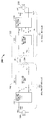
도 1은, 예시적인 실시형태에 따른, 전기 운송수단 (112) 을 충전하기 위한 예시적인 무선 전력 전송 시스템 (100) 의 도면이다. 무선 전력 전송 시스템 (100) 은, 전기 운송수단 (112) 이 베이스 무선 충전 시스템 (102a) 근처에 주차하고 있는 동안 전기 운송수단 (112) 의 충전을 가능하게 한다. 주차 구역에서의 2대의 전기 운송수단들에 대한 충전 공간들이 예시된다. 각각의 충전 공간은, 전기 운송수단이 충전 공간으로 운전해 들어가고 베이스 무선 충전 시스템들 (102a 및 102b) 과 같은 베이스 무선 충전 시스템 위에 주차하도록 구성된다. 몇몇 실시형태들에서, 로컬 분배 센터 (local distribution center; 130) 는 전력 백본 (power backbone; 132) 에 연결되고 베이스 무선 충전 시스템 (102b) 으로 전력 링크 (110) 를 통해 교류 (AC) 또는 직류 (DC) 공급을 제공하도록 구성될 수도 있다. 전력 링크는 거리를 따라 전력을 전송하기 위한 전기 케이블, 코드, 와이어, 또는 다른 디바이스일 수도 있다. 몇몇 실시형태들에서, 전력 백본 (132) 은 전력 링크 (110) 를 통해 하나의 베이스 무선 충전 시스템으로 전력을 공급하고; 다른 실시형태들에서, 전력 백본 (132) 은 전력 링크 (110) 를 통해 2개 이상의 베이스 무선 충전 시스템들로 전력을 공급할 수도 있다. 따라서, 몇몇 실시형태들에서, 전력 링크 (110) 는 베이스 무선 충전 시스템 (102b) 을 넘어 연장하여, 베이스 무선 충전 시스템 (102a) 과 같은 추가적인 베이스 무선 충전 시스템들로 전력을 전달한다. 이하의 설명은 베이스 무선 충전 시스템 (102a) 과 그 여러 컴포넌트들을 참조할 것이지만, 그 설명은 베이스 무선 충전 시스템 (102b) 에 그리고 무선 전력 전송 시스템 (100) 내에 포함된 임의의 추가적인 베이스 무선 충전 시스템들에 또한 적용가능하다.1 is a diagram of an exemplary wireless
로컬 분배 (130) 는 통신 백홀 (134) 을 통해 외부 소스들 (예를 들면, 전력 그리드) 과, 그리고 예를 들면 통신 링크 (108) 를 통해 베이스 무선 충전 시스템들 (102a) 과 같은 모든 베이스 무선 충전 시스템들과 통신하도록 구성될 수도 있다. 통신 링크 (108) 는 거리를 따라 신호들을 전송하기 위한 하나 이상의 케이블들 또는 다른 디바이스들을 포함할 수도 있다.The
다양한 실시형태들의 베이스 무선 충전 시스템 (102a) 은 전력을 무선으로 전송하거나 수신하기 위한 베이스 시스템 유도 코일 (104a) 을 포함한다. 전기 운송수단 (112) 이 베이스 무선 충전 시스템 (102a) 의 범위 내에 있으면, 전기 운송수단 (112) 내의 전기 운송수단 유도 코일 (116) 과 베이스 무선 유도 코일 (104a) 사이에서 전력이 전송될 수도 있다. 몇몇 실시형태들에서, 전력은 베이스 무선 유도 코일 (104a) 로부터 전기 운송수단 유도 코일 (116) 로 송신될 수도 있다. 그 다음, 전기 운송수단 유도 코일 (116) 에 의해 수신된 전력은 전기 운송수단 (112) 에 전력을 공급하기 위해 전기 운송수단 (112) 내의 하나 이상의 컴포넌트들로 전달될 수도 있다. 전기 운송수단 (112) 내의 이러한 컴포넌트들은, 예를 들면, 배터리 유닛 (118) 및 전기 운송수단 무선 충전 시스템 (114) 을 포함한다.The base
몇몇 예시적인 실시형태들에서, 전기 운송수단 유도 코일 (116) 이 베이스 시스템 유도 코일 (104a) 에 의해 생성된 전자기장의 목표 영역 내에 로케이팅될 때, 전기 운송수단 유도 코일 (116) 은 베이스 시스템 유도 코일 (104a) 의 범위 내에 있다고 말해지고, 베이스 시스템 유도 코일 (104a) 로부터 전력을 수신할 수도 있다. 목표 영역은, 베이스 시스템 유도 코일 (104a) 에 의해 출력되는 에너지가 전기 운송수단 유도 코일 (116) 에 의해 캡쳐될 수도 있는 영역의 적어도 일부에 대응한다. 몇몇 경우들에서, 목표 범위는 베이스 시스템 유도 코일 (104a) 의 "근접장 (near-field) 에 대응할 수도 있다. 근접장은 베이스 시스템 유도 코일 (104a) 에 의해 생성된 전자기장의 적어도 일부이다. 근접장은, 베이스 시스템 유도 코일 (104a) 에서의 전하들 및 전류들로부터 유래하며 베이스 시스템 유도 코일 (104a) 로부터 떨어져 전력을 방사하지 않는 강한 반응성 필드들이 존재하는 영역에 대응할 수도 있다. 몇몇 경우들에서, 근접장은, 베이스 시스템 유도 코일 (104a) 의 파장의 대략 1/2π 내에 있는 영역에 대응할 수도 있다. 추가적으로, 하기에 더 상세히 설명되는 다양한 실시형태들에서, 전력은 전기 운송수단 유도 코일 (116) 로부터 베이스 시스템 유도 코일 (104a) 로 송신될 수도 있다. 이러한 실시형태들에서, 근접장은, 전기 운송수단 유도 코일 (116) 의 파장의 대략 1/2π 내에 있는 영역에 대응할 수도 있다.In some exemplary embodiments, when the electric
다양한 실시형태들에서, 전기 운송수단 유도 코일 (116) 이 베이스 시스템 유도 코일 (104a) 의 근접장 영역 내에 배치되도록 전기 운송수단 유도 코일 (116) 을 정렬하는 것은, 유익하게도 전력 전송 효율을 향상시키거나 최대화할 수도 있다. 몇몇 실시형태들에서, 전기 운송수단 유도 코일 (116) 은 베이스 시스템 유도 코일 (104a) 과 정렬될 수도 있고, 따라서, 베이스 시스템 유도 코일 (104a) 에 대해 전기 운송수단 (112) 을 적절히 정렬하는 드라이버에 의해 간단히 근접장 내에 배치될 수도 있다. 다른 실시형태들에서, 드라이버는, 전기 운송수단 (112) 이 무선 전력 전송에 대해 적절히 위치되는 때를 결정하기 위해 시각적 피드백, 청각적 피드백, 또는 이들의 조합들을 제공받을 수도 있다. 또 다른 실시형태들에서, 전기 운송수단 (112) 은 오토파일럿 시스템에 의해 위치될 수도 있는데, 오토파일럿 시스템은 정렬 오차가 허용가능한 값에 도달할 때까지 전기 운송수단 (112) 을 (예를 들면, 지그재그 움직임들로) 앞뒤로 이동시킬 수도 있다. 이것은, 전기 운송수단 (112) 이 서보 스티어링 휠, 초음파 센서들, 및 운송수단을 조정하기 위한 지능을 갖추고 있다면, 드라이버 개입 없이 또는 최소한의 드라이버 개입만으로 전기 운송수단 (112) 에 의해 자동적으로 그리고 자율적으로 수행될 수도 있다. 또 다른 실시형태들에서, 전기 운송수단 유도 코일 (116), 베이스 시스템 유도 코일 (104a), 또는 이들의 조합은, 유도 코일들 (116 및 104a) 의 방향을 더 정확하게 맞추고 그들 사이에 더 효율적인 커플링을 전개시키기 위해, 그들을 서로에 대해 옮기고 이동시키기 위한 기능성을 구비할 수도 있다.In various embodiments, aligning the electric
베이스 무선 충전 시스템 (102a) 은 다양한 로케이션들에 로케이팅될 수도 있다. 비제한적인 예들로서, 몇몇 적절한 로케이션들은 전기 운송수단 (112) 소유자의 가정에 있는 주차 구역, 종래의 석유 기반의 주유소를 따라 모델링된 전기 운송수단 무선 충전용으로 확보된 주차 구역들, 및 사업장들 (places of employment) 및 쇼핑 센터들과 같은 다른 로케이션들에 있는 주차장들을 포함한다.The base
무선으로 전기 운송수단들을 충전하는 것은 다양한 이점들을 제공할 수도 있다. 예를 들면, 충전은 실제 드라이버 개입 및 조작들 없이 자동적으로 수행될 수도 있고, 그 결과 유저들에 대한 편의성을 향상시키게 된다. 또한, 노출된 전기 접점들 및 기계적 마모가 없을 수도 있고, 그 결과 무선 전력 전송 시스템 (100) 의 신뢰성을 향상시키게 된다. 케이블들 및 커넥터들에 의한 조작들이 회피될 수 있고, 실외 환경에서 습기와 물에 노출될 수도 있는 케이블들, 플러그들, 또는 소켓들이 없을 수도 있어서, 안전성을 향상시키게 된다. 또한, 보이거나 접근 가능한 소켓들, 케이블들, 및 플러그들이 없을 수도 있어서, 전력 충전 디바이스들의 잠재적인 파괴행위 (potential vandalism) 를 줄이게 된다. 또한, 전기 운송수단 (112) 이 전력 그리드를 안정화시키기 위한 분산된 저장 디바이스들로서 사용될 수도 있기 때문에, V2G (Vehicle-to-Grid; 운송수단 대 그리드) 동작에 대한 운송수단들의 이용가능성을 향상시키도록 도킹-투-그리드 솔루션 (docking-to-grid solution) 이 사용될 수도 있다.Charging electric vehicles wirelessly may provide a variety of advantages. For example, charging may be performed automatically without actual driver intervention and manipulations, resulting in improved convenience for users. In addition, there may be no exposed electrical contacts and mechanical wear, resulting in improved reliability of the wireless
도 1을 참조로 설명된 바와 같은 무선 전력 전송 시스템 (100) 은 심미적인 그리고 방해가 없는 이점들을 또한 제공할 수도 있다. 예를 들면, 운송수단들 및/또는 보행자들에게 방해가 될 수도 있는 충전 열들 (columns) 및 케이블이 없을 수도 있다.The wireless
운송수단 대 그리드 성능의 추가적인 설명으로서, 무선 전력 송수신 성능들은, 예를 들면, 에너지 부족시, 베이스 무선 충전 시스템 (102a) 이 전기 운송수단 (112) 으로 전력을 전송하고 그리고 전기 운송수단 (112) 이 베이스 무선 충전 시스템 (102a) 으로 전력을 송신하도록 하는 상호적이도록 구성될 수도 있다. 이 성능은, 과도한 요구에 의해 야기되는 에너지 부족시 또는 신재생 에너지 생산 (예를 들면, 풍력 또는 태양에너지) 에서의 부족시 전기 운송수단이 전체 분배 시스템에 전력을 기여하는 것을 허용하는 것에 의해 전력 분배 그리드를 안정화시키는데 유용할 수도 있다.As a further illustration of the vehicle-to-grid performance, the wireless power transmission and reception capabilities may be used to provide a base
도 2는 도 1의 무선 전력 전송 시스템 (100) 의 예시적인 컴포넌트들의 개략도이다. 도 2에 도시된 바와 같이, 무선 전력 전송 시스템 (200) 은 베이스 무선 전력 충전 시스템 (202) 을 포함할 수도 있고, 이것은 인덕턴스 L1을 갖는 베이스 시스템 유도 코일 (204) 을 구비하는 베이스 시스템 송신 회로 (206) 를 포함할 수도 있다. 무선 전력 전송 시스템 (200) 은 전기 운송수단 충전 시스템을 더 포함하고, 이것은 인덕턴스 L2를 갖는 전기 운송수단 유도 코일 (216) 을 구비하는 전기 운송수단 수신 회로 (222) 를 포함한다. 본원에서 설명되는 어떤 실시형태들은, 1차 구조체 (송신기) 와 2차 구조체 (수신기) 양자가 공통의 공진 주파수로 동조되면, 자기 또는 전자기 근접장을 통해 1차 구조체로부터의 에너지를 2차 구조체에 효율적으로 커플링시킬 수 있는 공진 구조를 형성하기 위해 용량적으로 부하된 (capacitively loaded) 와이어 루프들 (즉, 다중 턴 코일들 (multi-turn coils)) 을 사용할 수도 있다. 몇몇 이러한 실시형태들에서, 전기 운송수단 유도 코일 (216) 및 베이스 시스템 유도 코일 (204) 각각은 다중 턴 코일들을 포함할 수도 있다. 에너지 커플링을 위해 공진 구조들을 사용하는 것은, "자기 감응 공진 (magnetic coupled resonance) ", "전자기 감응 공진", 및/또는 "공진 유도"로 칭해질 수도 있다. 무선 전력 전송 시스템 (200) 의 동작은, 베이스 무선 전력 충전 시스템 (202) 에서 전기 운송수단 (112) 으로의 전력 전송에 기초하여 설명될 것이지만, 이에 제한되는 것은 아니다. 예를 들면, 위에서 언급된 바와 같이, 전기 운송수단 (112) 은 베이스 무선 충전 시스템 (102a) 으로 전력을 전송할 수도 있다.2 is a schematic diagram of exemplary components of the wireless
도 2를 참조하면, 전원 (208) (예를 들면, AC 또는 DC) 이 베이스 무선 전력 충전 시스템 (202) 으로 전력 (PSDC) 을 공급하여 전기 운송수단 (112) 으로 에너지를 전송하게 된다.Referring to FIG. 2, a power source 208 (e.g., AC or DC) provides power PSDC to the base radio
베이스 무선 전력 충전 시스템 (202) 은 베이스 충전 시스템 전력 컨버터 (236) 를 포함한다. 베이스 충전 시스템 전력 컨버터 (236) 는, 적절한 전압 레벨에서 표준 전원의 (standard mains) AC에서 DC 전력으로 전력을 변환하도록 구성된 AC/DC 컨버터, 및 DC 전력을 무선 고전력 전송에 적합한 동작 주파수의 전력으로 변환하도록 구성된 DC/저주파 (low frequency; LF) 컨버터와 같은 회로부를 포함할 수도 있다. 베이스 충전 시스템 전력 컨버터 (236) 는, 소망의 주파수에서 전자기장을 방출하기 위해, 전력 P1을 베이스 시스템 송신 회로 (206) 로 공급하는데, 베이스 시스템 송신 회로 (206) 는 반응성 동조 컴포넌트들을 직렬 또는 병렬 구성으로 또는 양자의 조합들로 포함할 수도 있는 베이스 충전 시스템 동조 회로 (205) 및 베이스 시스템 유도 코일 (204) 을 포함한다. 일 실시형태에서, 소망의 주파수에서 공진하는 베이스 시스템 유도 코일 (204) 을 갖는 공진 회로를 형성하기 위해 커패시터가 제공될 수도 있다. 베이스 시스템 유도 코일 (204) 은 전력 P1을 수신하고 전기 운송수단 (112) 을 충전하거나 전기 운송수단 (112) 에 전력을 공급하기에 충분한 레벨에서 전력을 무선으로 송신한다. 예를 들면, 베이스 시스템 유도 코일 (204) 에 의해 무선으로 제공되는 전력 레벨은 킬로와트 (kW) (예를 들면, 어디에서든 1kW에서 110kW 또는 그 이상 또는 그 이하) 정도일 수도 있다.The base wireless
베이스 시스템 유도 코일 (204) 을 포함하는 베이스 시스템 송신 회로 (206), 및 전기 운송수단 유도 코일 (216) 을 포함하는 전기 운송수단 수신 회로 (222) 는, 실질적으로 동일한 주파수들로 동조될 수도 있고 베이스 시스템 유도 코일 (204) 및 전기 운송수단 유도 코일 (216) 중 하나에 의해 송신된 전자기장의 근접장 내에 위치될 수도 있다. 이 경우, 베이스 시스템 유도 코일 (204) 과 전기 운송수단 유도 코일 (216) 은, 전기 운송수단 충전 시스템 동조 회로 (221) 및 전기 운송수단 유도 코일 (216) 을 포함하는 전기 운송수단 수신 회로 (222) 로 전력이 전송될 수도 있도록 그들 사이의 전자기장을 통해 서로 커플링되게 될 수도 있다. 전기 운송수단 충전 시스템 동조 회로 (221) 는 전기 운송수단 유도 코일 (216) 을 갖는 공진 회로를 형성하도록 제공될 수도 있고 그 결과 전기 운송수단 유도 코일 (216) 은 소망의 주파수에서 공진하게 된다. 코일 분리에서 발생하는 상호 커플링 계수는 엘리먼트 k(d) 에 의해 표현된다. 등가 저항들 (Req ,1 및 Req ,2) 은, 몇몇 실시형태들에서, 베이스 충전 시스템 동조 회로 (205) 및 전기 운송수단 충전 시스템 동조 회로 (221) 에서 각각 제공될 수도 있는 임의의 안티-리액턴스 (anti-reactance) 커패시터들 및 유도 코일들 (204 및 216) 에 내재될 수도 있는 손실들을 나타낸다. 전기 운송수단 유도 코일 (216) 및 전기 운송수단 충전 시스템 동조 회로 (221) 를 포함하는 전기 운송수단 수신 회로 (222) 는 유도 코일들 (204 및 216) 사이의 전자기장을 통해 베이스 무선 전력 충전 시스템 (202) 으로부터 전력 P2를 수신한다. 그 다음, 전기 운송수단 수신 회로 (222) 는 전기 운송수단 (112) 에 의한 전력의 사용을 가능하게 하기 위해 그 전력 P2를 전기 운송수단 충전 시스템 (214) 의 전기 운송수단 전력 컨버터 (238) 로 제공한다.The
전기 운송수단 전력 컨버터 (238) 는, 무엇보다도, 동작 주파수의 전력을, 전기 운송수단 배터리 유닛 (218) 의 전압 레벨에 매치하는 전압 레벨의 DC 전력으로 다시 변환하도록 구성된 LF/DC 컨버터를 포함할 수도 있다. 전기 운송수단 전력 컨버터 (238) 는, 전기 운송수단 배터리 유닛 (218) 을 충전하기 위해, 변환된 전력 (PLDC) 을 제공할 수도 있다. 전원 (208), 베이스 충전 시스템 전력 컨버터 (236), 및 베이스 시스템 유도 코일 (204) 은 고정식일 수도 있고 위에서 논의된 바와 같이 다양한 로케이션들에 로케이팅될 수도 있다. 배터리 유닛 (218), 전기 운송수단 전력 컨버터 (238), 및 전기 운송수단 유도 코일 (216) 은 전기 운송수단 (112) 의 일부 또는 배터리 팩 (도시되지 않음) 의 일부인 전기 운송수단 충전 시스템 (214) 에 포함될 수도 있다. 전기 운송수단 충전 시스템 (214) 은 그리드로 다시 전력을 공급하기 위해 전기 운송수단 유도 코일 (216) 을 통해 베이스 무선 전력 충전 시스템 (202) 으로 무선으로 전력을 공급하도록 또한 구성될 수도 있다. 전기 운송수단 유도 코일 (216) 및 베이스 시스템 유도 코일 (204) 의 각각은 동작 모드에 기초하여 송신 또는 수신 유도 코일들로서 작용할 수도 있다.The electric
도시되진 않았지만, 무선 전력 전송 시스템 (200) 은 무선 전력 전송 시스템 (200) 으로부터 전기 운송수단 배터리 유닛 (218) 또는 전원 (208) 을 안전하게 단절하기 위해 부하 단절 유닛 (load disconnect unit; LDU) 을 포함할 수도 있다. 예를 들면, 비상상황 또는 시스템 고장의 경우에, LDU는 무선 전력 전송 시스템 (200) 으로부터의 부하를 단절하도록 트리거될 수도 있다. LDU는 배터리 충전을 관리하기 위한 배터리 관리 시스템에 추가하여 제공될 수도 있거나, 또는 배터리 관리 시스템의 일부일 수도 있다.Although not shown, the wireless
또한, 전기 운송수단 충전 시스템 (214) 은 전기 운송수단 전력 컨버터 (238) 에 전기 운송수단 유도 코일 (216) 을 선택적으로 연결하거나 단절하기 위한 스위칭 회로부 (도시되지 않음) 를 포함할 수도 있다. 전기 운송수단 유도 코일 (216) 을 단절하는 것은 충전을 일시정지할 수도 있고 또한 (송신기로서 작용하는) 베이스 무선 충전 시스템 (202) 에 의해 "보이는 것과 같은" "부하"를 조정할 수도 있는데, 그것은 베이스 무선 충전 시스템 (202) 으로부터 (수신기로서 작용하는) 전기 운송수단 충전 시스템 (214) 을 디커플링하는 데 사용될 수도 있다. 부하 변경들은 송신기가 부하 감지 회로를 포함하면 검출될 수도 있다. 따라서, 송신기, 예컨대 베이스 무선 충전 시스템 (202) 은, 수신기들, 예컨대 전기 운송수단 충전 시스템 (214) 이 베이스 시스템 유도 코일 (204) 의 근접장 내에 존재할 때를 결정하기 위한 메커니즘을 구비할 수도 있다.In addition, the electric
위에서 설명된 바와 같이, 동작에 있어서, 운송수단 또는 배터리로의 에너지 전송을 가정하면, 에너지 전송을 제공하기 위한 필드를 베이스 시스템 유도 코일 (204) 이 생성하도록 전원 (208) 으로부터 입력 전력이 제공된다. 전기 운송수단 유도 코일 (216) 은 방사된 필드에 커플링되어 전기 운송수단 (112) 에 의한 저장 또는 소비를 위한 출력 전력을 생성한다. 위에서 설명된 바와 같이, 몇몇 실시형태들에서, 베이스 시스템 유도 코일 (204) 및 전기 운송수단 유도 코일 (216) 은, 전기 운송수단 유도 코일 (216) 의 공진 주파수 및 베이스 시스템 유도 코일 (204) 의 공진 주파수가 아주 근접하거나 또는 실질적으로 동일하도록 하는 상호 공진 관계에 따라 구성된다. 베이스 무선 전력 충전 시스템 (202) 및 전기 운송수단 충전 시스템 (214) 사이의 송신 손실들은, 전기 운송수단 유도 코일 (216) 이 베이스 시스템 유도 코일 (204) 의 근접장 내에 로케이팅될 때 최소이다.As described above, in operation, assuming energy transfer to a vehicle or battery, input power is provided from the
언급한 바와 같이, 전자기파에서의 에너지의 대부분을 근접장을 넘어서 전송하는 것보다, 송신용 유도 코일의 근접장에서의 에너지의 대부분을 수신용 유도 코일에 커플링시킴으로써 효율적인 에너지 전송이 달성된다. 근접장 내에 있을 때, 송신 유도 코일과 수신 유도 코일 사이에 커플링 모드가 확립될 수도 있다. 이 근접장 커플링이 발생할 수도 있는 유도 코일들 주위의 구역은 본원에서 근접장 커플링 모드 영역으로 칭한다.As mentioned, efficient energy transfer is achieved by coupling most of the energy in the near-field of the transmitting inductive coil to the receiving inductive coil, rather than transmitting much of the energy in the electromagnetic wave beyond the near-field. When in the near field, a coupling mode may be established between the transmission induction coil and the reception induction coil. The area around the induction coils where this near field coupling may occur is referred to herein as the near field coupling mode region.
도시되지 않았지만, 베이스 충전 시스템 전력 컨버터 (236) 및 전기 운송수단 전력 컨버터 (238) 양자는 발진기, 전력 증폭기와 같은 드라이버 회로, 필터, 및 무선 전력 유도 코일과의 효율적인 커플링을 위한 매칭 회로를 포함할 수도 있다. 발진기는, 조정 신호에 응답하여 조정될 수도 있는 소망의 주파수를 생성하도록 구성될 수도 있다. 발진기 신호는 제어 신호들에 응답하는 증폭량으로 전력 증폭기에 의해 증폭될 수도 있다. 필터와 매칭회로는 조화파들 또는 다른 원치않는 주파수들을 걸러 내고 전력 변환 모듈의 임피던스를 무선 전력 유도 코일에 매치시키기 위해 포함될 수도 있다. 전력 컨버터들 (236 및 238) 은, 배터리를 충전하기 위한 적절한 전력 출력을 생성하기 위해, 정류기와 스위칭 회로부를 또한 포함할 수도 있다.Although not shown, both the base charging
전기 운송수단 유도 코일 (216) 및 베이스 시스템 유도 코일 (204) 은, 개시된 실시형태들에 걸쳐 설명된 바와 같이, "루프" 안테나들로서, 특히, 다중 턴 루프 안테나들로서 칭해지거나 또는 구성될 수도 있다. 유도 코일들 (204 및 216) 은 본원에서 "자기" 안테나들로서 칭해지거나 또는 구성될 수도 있다. 용어 "코일" 은 다른 "코일" 에 커플링하기 위한 에너지를 무선으로 출력하거나 수신할 수도 있는 컴포넌트를 지칭하도록 의도된다. 코일은 또한 전력을 무선으로 출력하거나 수신하도록 구성되는 타입의 "안테나" 로서 지칭될 수도 있다. 본원에서 사용된 바와 같이, 코일들 (204 및 216) 은, 전력을 무선으로 출력하고, 무선으로 수신하고, 및/또는 무선으로 중계하도록 구성된 타입의 "전력 전송 컴포넌트들"의 예들이다. 루프 (예를 들면, 다중 턴 루프) 안테나들은 공심 (air core), 또는 페라이트 코어와 같은 물리적 코어를 포함하도록 구성될 수도 있다. 또한, 공심 루프 안테나는 코어 구역 내에서의 다른 컴포넌트들의 배치를 허용할 수도 있다. 강자성 재료들을 포함하는 물리적 코어 안테나들은, 더 강한 전자기장의 전개 및 향상된 커플링을 허용할 수도 있다.The electric
위에서 논의된 바와 같이, 송신기와 수신기 사이의 에너지의 효율적인 전송은, 송신기와 수신기 사이의 매칭된 또는 거의 매칭된 공진 동안 발생한다. 그러나, 송신기와 수신기 사이의 공진이 매치하지 않는 경우에도, 에너지는 낮은 효율로 전송될 수도 있다. 에너지의 전송은, 송신용 유도 코일의 근접장으로부터의 에너지를, 이 근접장이 송신용 유도 코일로부터 자유 공간으로 에너지를 전달하는 대신 확립될 수 있는 영역 내에 (예를 들면, 공진 주파수의 미리 결정된 주파수 범위 내에, 또는 근접장 영역의 미리 결정된 거리 내에) 있는 수신용 유도 코일에 커플링시킴으로써 발생한다.As discussed above, efficient transmission of energy between a transmitter and a receiver occurs during a matched or nearly matched resonance between the transmitter and the receiver. However, even if the resonance between the transmitter and the receiver does not match, the energy may be transmitted with low efficiency. The transfer of energy is achieved by transferring the energy from the near field of the induction coil for transmission to an area in which this near field can be established instead of transferring energy from the induction coil to the free space (e.g., within a predetermined frequency range Or within a predetermined distance of the near field region).
공진 주파수는, 위에서 설명된 바와 같이 유도 코일 (예를 들면, 베이스 시스템 유도 코일 (204)) 을 포함하는 송신 회로의 커패시턴스와 인덕턴스에 기초할 수도 있다. 도 2에 도시된 바와 같이, 인덕턴스는 일반적으로 유도 코일의 인덕턴스일 수도 있지만, 반면, 커패시턴스는 소망의 공진 주파수에서 공진 구조체를 생성하기 위해 유도 코일 (예를 들면, 유도 코일 (204)) 에 더해질 수도 있다. 비제한적인 예로서, 커패시터 (도시되지 않음) 는, 전자기장을 생성하는 공진 회로 (예를 들면, 베이스 시스템 송신 회로 (206)) 를 생성하기 위해 유도 코일 (예를 들면, 유도 코일 (204)) 과 직렬로 추가될 수도 있다. 따라서, 더 큰 직경의 유도 코일들에 대해, 공진을 유도하기 위한 커패시턴스의 값은 코일의 직경 또는 인덕턴스가 증가함에 따라 감소할 수도 있다. 또한, 인덕턴스는 유도 코일의 턴들의 수에 의존할 수도 있다. 또한, 유도 코일의 직경이 증가할수록, 근접장의 유효 에너지 전송 구역은 증가할 수도 있다. 다른 공진 회로들이 가능하다. 다른 비제한적인 예로서, 커패시터는 유도 코일 (예를 들면, 병렬 공진 회로) 의 두 단자들 사이에 병렬로 배치될 수도 있다. 또한, 유도 코일은, 유도 코일의 공진성을 향상시키기 위한 높은 품질 (Q) 인자를 갖도록 설계될 수도 있다.The resonant frequency may be based on the capacitance and inductance of the transmitting circuit including the induction coil (e.g., the base system induction coil 204) as described above. 2, the inductance may generally be the inductance of the inductive coil, while the capacitance is added to the inductive coil (e.g., induction coil 204) to produce a resonant structure at the desired resonant frequency It is possible. As a non-limiting example, a capacitor (not shown) may be coupled to an inductive coil (e.g., induction coil 204) to create a resonant circuit (e. G., A base system transmit circuit 206) And may be added in series. Thus, for larger diameter induction coils, the value of the capacitance to induce resonance may decrease as the diameter or inductance of the coil increases. In addition, the inductance may depend on the number of turns of the induction coil. Also, as the diameter of the induction coil increases, the effective energy transfer area of the near field may increase. Other resonant circuits are possible. As another non-limiting example, the capacitors may be arranged in parallel between two terminals of an inductive coil (e.g., a parallel resonant circuit). Further, the induction coil may be designed to have a high quality (Q) factor for improving the resonance of the induction coil.
위에서 설명된 바와 같이, 몇몇 실시형태들에 따르면, 서로 근접장 내에 있는 두 유도 코일들 사이의 커플링 전력이 개시된다. 위에서 설명된 바와 같이, 근접장은, 전자기장들이 존재하지만 그러나 그 유도 코일로부터 떨어져 전파하거나 방사하지 않는, 유도 코일 주위의 영역에 대응할 수도 있다. 근접장 커플링 모드 영역들은, 유도 코일의 물리적 볼륨 근처에 있는, 특히 파장의 작은 단편 (fraction) 내에 있는 볼륨에 대응할 수도 있다. 몇몇 실시형태들에 따르면, 전기 타입의 안테나 (예를 들면, 작은 다이폴) 의 전기 근접장들과 비교하여, 실제 실시형태들에서의 자가 근접장 진폭들이 자기 타입의 코일들에 대해 더 높은 경향이 있기 때문에, 단일 및 다중 턴 루프 안테나들과 같은 전자기 유도 코일들은 송신 및 수신 양자에 대해 사용된다. 이것은 쌍 사이의 잠재적으로 더 높은 커플링을 허용한다. 또한, "전기" 안테나 (예를 들면, 다이폴들 및 모노폴들) 또는 자기 및 전기 안테나들의 조합이 사용될 수도 있다.As described above, according to some embodiments, the coupling power between two induction coils in close proximity to one another is disclosed. As described above, the near field may correspond to an area around the induction coil, in which electromagnetic fields exist, but do not propagate or emit away from the induction coil. The near field coupling mode regions may correspond to a volume in the vicinity of the physical volume of the induction coil, especially in a small fraction of the wavelength. According to some embodiments, the self-near field amplitudes in practical embodiments tend to be higher for coils of the magnetic type, as compared to the electrical near-field of an electrical type of antenna (e.g., a small dipole) , Electromagnetic induction coils such as single and multiple turn loop antennas are used for both transmit and receive. This allows a potentially higher coupling between the pair. Also, a "electrical" antenna (e.g., dipoles and monopoles) or a combination of magnetic and electrical antennas may be used.
도 3은 도 1의 각각의 유도 코일들 (116 또는 104a), 또는 도 2의 베이스 시스템 송신 회로 (206) 또는 전기 운송수단 수신 회로 (222) 를 포함하는 모듈들의 예시적인 구성의 단면도이다. 이들 모듈들은 본원에서 무선 전력 전송 디바이스들로서 일반적으로 설명될 수도 있다.FIG. 3 is a cross-sectional view of an exemplary configuration of modules including
도 3의 무선 전력 전송 디바이스 (300) 는 케이싱 (301) 을 포함한다. 케이싱부 (301) 는 임의의 적절한 내구성 재료로 이루어질 수도 있지만, 어떤 실시형태들에서, 케이싱은 경질의 (rigid) 또는 반 경질의 플라스틱 재료 또는 다른 플라스틱 또는 복합 재료, 예를 들면, 폴리에틸렌으로 이루어질 수도 있다. 폴리에틸렌은 화학적 내성 및 수밀성과 함께 내충격 특성들을 제공하며, 이것은 무선 전력 전송 디바이스 (300) 가 경험할 가능성이 있는 조건들의 범위에 대한 노출에 직면하여 케이싱의 무결성을 유지하는 데 적합할 수도 있다. 또한, 폴리에틸렌은 비틀림 없이 상대적으로 높은 온도들을 견딜 수 있고, 이것은 제조 동안 그리고 또한 높은 온도들을 경험하는 환경들 내에서의 사용 둘 다에서 케이싱의 형상 유지에 관해 유용할 수도 있다. 중밀도 폴리에티렌 (medium density polyethylene; MDPE) 은 케이싱에 대해 상대적으로 저가의 재료를 제공할 수도 있으며, 또한 쉽게 가공될 수도 있다. 고밀도 폴리에틸렌 (high density polyethylene; HDPE) 은 더 쉽게 가공될 수도 있지만, 디바이스 (300) 의 비용을 증가시킬 수 있을 것이다. 케이싱에 대한 적절한 재료임을 폴리에틸렌에 부여하는 특성들을 갖는 것으로 폴리에틸렌이 설명되었지만, 이것은 제한하는 것으로 의도된 것은 아님이 인식되어야만 한다. 당업자라면, 플라스틱이든 아니든 다른 재료들도 사용될 수도 있음을 인식해야만 한다.The wireless
무선 전력 전송 디바이스 (300) 는 케이싱 (301) 내에 위치된 유도 코일 (302) 을 더 포함할 수도 있다. 어떤 실시형태에서, 코일 (302) 은 하나 이상의 길이들의 도전 재료, 예를 들면 리츠 (Litz) 와이어로부터 형성될 수도 있다.The wireless
페라이트 블록들 (303) 로서 도 3에 도시된 자기적으로 침투성인 부재들 또는 강자성 안테나 코어들은, 코일 (302) 및 페라이트 블록들 (303) 사이의 전기적 분리를 제공하기 위해 절연층 (304) 에 의해 유도 코일 (302) 로부터 분리될 수도 있다.The magnetically permeable members or ferromagnetic antenna cores shown in FIG. 3 as ferrite blocks 303 may be formed on the insulating
백킹 플레이트 (305) 는 디바이스 (300) 에 추가적인 기계적 강도를 제공하고 케이싱 (301) 내에 컴포넌트들을 포함하도록 제 1의 케이싱부 (301) 에 연결될 수도 있다. 백킹 플레이트 (305) 는, 예를 들면 무선 전력 전송 디바이스 (300) 가 전자 운송수단의 픽업인 경우 (도 1의 예시적인 유도 코일 (116) 참조) 에 실장 표면으로서 작용할 수도 있다. 백킹 플레이트 (305) 는, 전자기 실드로서 작용하기 위해, 예를 들면, 알루미늄, 구리, 또는 다른 전도성 금송 또는 전도성 복합물과 같은 전도성 재료로 이루어질 수도 있다.The
케이싱부 (301) 는 에폭시 수지 (306) 형태의 경화가능한 유동성 매체로 충전되거나 채워질 수도 있다. 일 예시적인 실시형태에서, 에폭시 수지 (306) 는 대략 725 센티푸아즈의 작업 점도를 갖는 마린 그레이드 에폭시 (marine grade epoxy) 이다. 이 예는 제한적인 것으로 의도된 것이 아니며, 다른 적절한 경화가능한 유동성 매체가 본 개시의 이 실시형태와 함께 구현될 수도 있음이 인식되어야만 한다. 경화가능한 유동성 매체에 대한 참조는, 고체를 형성하기 위한 경화 과정을 겪기 전에 유체 방식으로 확산될 수도 있는 임의의 재료를 의미하도록 이해되어야만 한다. 미경화 유동성 매체는 고체 및 액체 성분들 둘 다 - 예를 들면 액체 수지 내의 고체 섬유들 또는 입자들을 포함할 수도 있음이 인식되어야만 한다.The
경화되면, 에폭시 (306) 는 케이싱 (301) 의 내부 내에서 강화성 (reinforcement) 을 제공할 수도 있다. 이것은, 지상 기반의 디바이스 위를 넘어 가는 운송수단, 또는 운송수단에 탑재된 디바이스에 충돌하는 특히 충격에 대한 내성의 관점에서, 무선 전력 전송 디바이스 (300) 에 대한 향상된 기계적 강도로 나타날 수도 있다. 이들 압축력들은, 순전히 케이싱 (301) 에 의한 것과는 반대로, 경화된 에폭시 (306) 에 걸쳐 더 균일하게 분포되거나 또는 그 경화된 에폭시 (306) 에 의해 저항을 받을 수도 있다.Once cured, the epoxy 306 may provide reinforcement within the interior of the
또한, 유도 코일 (302) 및 페라이트 블록들 (303) 을 인케이싱함으로써, 에폭시 (306) 는 방수 효과를 제공할 수도 있는데, 무선 전력 전송 디바이스 (300) 가 젖은 상태에서 안전하게 사용되도록 하는 것을 보조하기 위해서는, 이것이 아주 바람직하다.In addition, by encircling the
또한, 에폭시 (306) 내에 페라이트 블록들 (303) 을 인케이싱함으로써, 무선 전력 전송 디바이스 (300) 의 전기 특성들에 대한 영향들은, 페라이트 블록들 (303) 중 하나 이상이 크랙되는 경우에 최소화될 수도 있다. 이것은, 운송수단들이 디바이스들을 넘어서 통과할 수 있는 지중에 또는 지상에 배치된 디바이스들에 대해서는 불가피할 수도 있다. 에폭시 (306) 는, 무선 전력 전송 디바이스 (300) 의 동작의 목적들을 위해, 블록들 (303) 의 특성들이 유지되도록 블록들 (303) 의 형태를 실질적으로 유지하도록 기능할 수도 있다.In addition, by encasing the ferrite blocks 303 in the epoxy 306, the effects on the electrical properties of the wireless
에폭시 (306) 는 케이싱 내의 컴포넌트들 사이에 전기적 절연체로서 작용할 수도 있다. 또한, 에폭시 (306) 는, 동작 동안 디바이스 (300) 의 가열을 줄이는 것을 보조하기 위해, 무선 전력 전송 디바이스 (300) 의 열 전도성을 또한 향상시킬 수도 있다.The epoxy 306 may act as an electrical insulator between the components in the casing. The epoxy 306 may also improve the thermal conductivity of the wireless
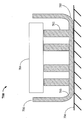
도 4는 도 3의 무선 전력 전송 디바이스 (300) 의 것과 유사한 구조의 무선 전력 전송 디바이스 (400) 를 예시하는데, 케이싱 (401), 유도 코일 (402), 페라이트 블록들 (403), 절연층 (404), 및 백킹 플레이트 (405) 를 포함한다.4 illustrates a wireless
도 4에 예시된 실시형태에서, 케이싱 (401) 의 제 1의 부분 (406) 은 에폭시 수지 형태의 제 1의 경화가능한 유동성 매체로 충전되거나 채워질 수도 있다. 일 실시형태에서, 에폭시 수지는 대략 725 센티푸아즈의 작업 점도를 갖는 마린 그레이드 에폭시 (marine grade epoxy) 이다.In the embodiment illustrated in Figure 4, the
케이싱 (401) 이 제 2의 부분 (407) 은 제 2의 경화가능한 유동성 매체로 또한 채워질 수도 있다. 어떤 실시형태들에서, 제 2의 경화가능한 유동성 매체는 제 1의 경화가능한 유동성 매체와 인터페이싱하고, 이것은 디바이스 (400) 의 강도를 향상시킬 수도 있다. 제 2의 경화가능한 유동성 매체는 제 1의 경화가능한 유동성 매체의 밀도보다 더 낮은 밀도를 가질 수도 있다. 일 실시형태에서, 제 2의 경화가능한 유동성 매체는 실리카 비드들과 혼합된 에폭시 수지일 수도 있고, 이것은 경량의, 비전도성의, 그리고 저가의 충전재 재료를 제공할 수도 있다. 그러나, 에폭시 수지 또는 실리카 비드들 중 어느 하나 대신 다른 비전도성/비자성의 재료들이 사용될 수도 있고, 다른 바람직한 특성들을 제공하기 위해 더 큰 밀도를 가질 수도 있다. 예를 들면, 대안적 실시형태에서, 제 1의 경화가능한 유동성 매체는 섬유질 재료와 혼합된 에폭시 수지이다. 잠재적으로 더 무겁지만, 혼합물은 디바이스 (400) 의 인장 강도를 증가시킬 수도 있다.The
용이한 참조를 위해, 이제 명세서에서, 케이싱 (401) 의 제 1의 부분 (406) 및 제 2의 부분 (407) 을 에폭시 층들 (406 및 407) 로 칭할 수도 있다.The
몇몇 실시형태들에서, 유도 코일 (402) 은, 절연층 (404), 및 페라이트 블록들 (403) 의 일부와 함께, 제 1의 더 높은 밀도의 에폭시 수지 층 (406) 내에 인케이싱된다. 이러한 배치는 이들 컴포넌트들을 서로에 대해 그리고 케이싱 (401) 에 대해 제자리에 고정하고 동시에 기계적 강도를 향상시키도록 기능할 수도 있다. 몇몇 실시형태들에서 기계적 강도를 향상시키기 위해, 유체 에폭시 층 (406) 이 케이싱 안으로 삽입할 때, 공기 기포들이, 예를 들면, 절연층 (404) 아래에 포획되지 않는 것을 보장하기 위해 특별한 조치가 요구될 수도 있는데; 이러한 공기 기포들은 경화된 층 내에서 결함들을 유발할 수도 있다.In some embodiments, the
몇몇 실시형태에서, 제 2의 경량의 에폭시 층 (407) 의 사용은, 케이싱 (401) 내에 강화 구조를 여전히 제공하면서, 자체로 더 높은 밀도의 에폭시를 활용하는 실시형태들과 비교하여, 무선 전력 전송 디바이스 (400) 의 전체 중량을 줄인다. 몇몇 실시형태들에서, 예를 들면, 실리카 비드들과 같은 하나 이상의 충전재 재료들의 사용은, 제 2의 에폭시 층 (407) 의 비용을 줄이는 것을 보조할 수도 있다.In some embodiments, the use of the second
몇몇 실시형태들에서, 층들의 기계적 특성들을 변경하기 위해 에폭시 층들 (406 및 407) 중 적어도 하나에 추가 재료가 추가된다. 예를 들면, 플렉스에 대한 내성이 가장 요구될 수도 있는 영역에서 디바이스 (400) 에 인장 강도를 추가하기 위해 페라이트 블록들 (403) 과 백킹 플레이트 (405) 사이에 유리 섬유 시트 (408) 가 추가될 수도 있다. 재료들과 그 비율들은 무선 전력 전송 디바이스 (400) 의 소망의 특성들에 따라 선택될 수도 있다. 예를 들면, 높은 트래픽 밀도 영역에서 사용하기 위한 디바이스는, 소망의 기계적 강도를 달성하기 위해 더 무거운 조성물이 허용될 수도 있다. 대안적으로, 공연 운송수단에서 사용하기 위한 운송수단 탑재 디바이스는, 전체 무게를 줄이기 위해 기계적 강도를 희생할 수도 있다.In some embodiments, additional material is added to at least one of the
경화가능한 유동성 매체의 추가적인 부분들 또는 층들이 사용될 수 있고, 이러한 사용은 본 개시에 의해 본원에서 고려된다는 것이 인식되어야만 한다. 경화가능한 유동성 매체의 특성들은, 매체가 접촉하게 되는 컴포넌트들과 적합하도록 또는 무선 전력 전송 디바이스 (400) 의 소망의 특성들을 달성하도록 선택될 수도 있다.It should be appreciated that additional portions or layers of curable fluid medium may be used and such use is contemplated herein by this disclosure. The properties of the curable fluid media may be selected to meet the desired properties of the wireless
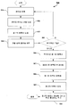
도 5는 도 4에 예시된 무선 전력 전송 디바이스 (400) 와 같은 무선 전력 전송 디바이스를 제조하는 예시적인 방법론 (500) 을 예시하는 흐름도이다. 방법론 (500) 을 설명하는 프로세스에서 도 4의 컴포넌트들을 참조할 것이다. 경화가능한 유동성 매체의 다수의 층들을 구현하는 방법론이 설명되지만, 그 프로세스는 도 3에 의해 예시된 것과 같은 단일의 경화가능한 유동성 매체로 채워진 무선 전력 전송 디바이스의 제조에도 또한 적용될 수도 있음이 인식되어야만 한다.FIG. 5 is a flow chart illustrating an
501에서, 케이싱 (401) 의 내부가 위쪽을 향햐도록 케이싱 (401) 은 반전된다. 502에서, 유도 코일 (402) 이 케이싱 (401) 에 도입된다. 503에서, 유도 코일 (402) 을 덮기 위해, 충분한 양의 제 1의 에폭시가 케이싱 (401) 에 도입된다. 어떤 실시형태들에서, 페라이트 블록들 (403) 의 일부를 또한 둘러싸기 위해, 충분한 양의 제 1의 에폭시가 도입된다. 504에서, 절연층 (404) 은 유도 코일 (402) 상에 배치된다.In 501, the
505에서, 추가적인 코일들의 층들이 요구되는 경우, 그렇게 하기 위해 단계들 502 내지 504가 반복될 수도 있다. 몇몇 실시형태들에서, 각각의 코일 층은 추가적인 코일의 도입 이전에 경화하도록 허용된다.At 505, if additional layers of coils are required, steps 502-504 may be repeated to do so. In some embodiments, each coil layer is allowed to cure prior to the introduction of additional coils.
506에서, 절연층 (404) 을 덮기 위해 추가적인 양의 제 1의 에폭시가 추가된다. 507에서, 페라이트 블록들 (403) 은 케이싱 (401) 내에 위치되고 컴포넌트들이 정렬되도록 압축되고, 페라이트 블록들 (403) 의 일부는 제 1의 에폭시 내에 있을 수도 있다. 508에서, 상기 언급된 단계들을 통해 도입된 제 1의 에폭시를 포함하는 제 1의 에폭시 층 (406) 의 형성이 완료된다; 아직 경화되지 않은 제 1의 에폭시 층 (406) 내의 임의의 제 1의 에폭시는 경화하도록 허용된다.At 506, an additional amount of a first epoxy is added to cover the insulating
509에서, 어떤 양의 제 2의 에폭가 케이싱 (401) 에 도입되어, 페라이트 블록들 (403) 의 남머지 노출된 부분을 덮는다. 몇몇 실시형태들에서, 제 2의 에폭시는 실리카 비드들을 포함한다. 510에서, 단계 509에서 도입된 제 2의 에폭시를 포함하는 제 2의 에폭시 층 (407) 은, 제 2의 에폭시 층 (407) 을 케이싱 (401) 의 에지와 동일면이 되도록 하고 백킹 플레이트 (405) 를 부착하기 이전에, 경화하도록 허용된다.At 509, a certain amount of the second epoxy is introduced into the
특히 압축력들에 저항하는 것과 관련하여 무선 전력 전송 디바이스의 기계적 강도를 향상시키는 데 보조하기 위해서는, 케이싱을 에폭시 층 (들) 과 화학적으로 연결하는 것이 바람직할 수도 있다. 재료의 기계적 특성들로 인해, 도 4에 의해 예시된 것과 같은 무선 전력 전송 디바이스의 케이싱에 대해 폴리에틸렌과 같은 재료를 사용하는 것이 유용할 수도 있지만, 상대적으로 높은 화학적 내성은, 그것이, 예를 들면, 에폭시 수지와 같은 경화가능한 유동성 매체와 결합하는 것에 저항할 수도 있다는 것을 의미한다. 따라서, 몇몇 실시형태들에서, 케이싱 및/또는 경화가능한 유동성 매체에 대해, 당업자들에게 일반적으로 알려진 다른 재료들이 선택될 수도 있다.It may be desirable to chemically connect the casing to the epoxy layer (s) to aid in improving the mechanical strength of the wireless power transfer device, particularly in relation to resisting compressive forces. Due to the mechanical properties of the material, it may be useful to use a material such as polyethylene for the casing of a wireless power transmission device, such as illustrated by Fig. 4, but a relatively high chemical resistance, It may be resistant to bonding with a curable fluid medium such as an epoxy resin. Thus, in some embodiments, for casings and / or curable fluid media, other materials generally known to those skilled in the art may be selected.
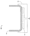
도 6은, 에폭시 수지 (602) 와 같은 경화가능한 유동성 매체가 도입되는 케이싱 (601) 을 포함하는 무선 전력 전송 디바이스 (600) 에서의 로케이팅 부분들의 사용을 예시한다. 로케이팅 부분에 대한 참조는 케이싱의 내면으로부터의 임의의 편차를 의미하는 것으로 이해되어야만 하며; 이러한 편차는 케이싱에 대한 경화된 유동청 매체의 움직임을 방해하는 데 도움이 될 수도 있다.6 illustrates the use of locating portions in a wireless
예를 들면, 로케이팅 부분은 유체 에폭시 (602) 를 받아 들이는 언더컷팅 부분 (undercutting portion; 603) 일 수도 있다. 마찬가지로, 로케이팅 부분은 케이싱 (601) 에서의 어퍼쳐 (604) 일 수도 있다. 이러한 로케이팅 부분들은 몇몇 실시형태들에서 케이싱에 쉽게 추가될 수도 있고, 잠재적으로 제조의 용이성을 보조하게 된다. 대안적으로, 또는 추가적으로, 로케이팅 부분은 케이싱 (601) 에 형성된 돌출부 (605) 및/또는 케이싱 (601) 의 어퍼쳐에 놓여진 인서트 (606) 일 수도 있다.For example, the locating portion may be an undercutting
에폭시 (602) 가 일단 경화되면, 케이싱 (601) 에 대한 에폭시 (602) 의 움직임은, 에폭시 (602) 와 로케이팅 부분들 (603, 604, 605, 또는 606) 사이의 기계적 상호작용에 의해 제한된다. 몇몇 실시형태들에서, 인서트 (606) 는, 추가적인 연결도 (additional degree of connection) 를 제공하기 위해 에폭시 (602) 와 화학적으로 반응하는 재료로 이루어진다.Once the
도 5에서 단일 층의 에폭시가 예시되었지만, 도 4를 참조로 설명된 이중 층 구성 및 다중 층 구성들도 본 개시의 양태들과 함께 또한 활용될 수도 있음이 인식되어야만 한다.Although a single layer epoxy is illustrated in FIG. 5, it should be appreciated that the dual layer construction and multilayer construction described with reference to FIG. 4 may also be utilized with aspects of the present disclosure.
디바이스의 제조 동안, 도 3 또는 도 4에서 예시된 것과 같은 무선 전력 디바이스의 케이싱의 선택된 형상을 유지하는 것이 일반적으로 바람직할 수도 있다. 특히, 케이싱의 상부 또는 하부 표면들을 편평하게 유지하는 것이 바람직할 수도 있는데, 그 이유는 케이싱에서의 임의의 곡면이 무거운 운송수단들이 위로 운전해 지나갈 때 특히 크랙되기 쉬울 수도 있기 때문이다. 케이싱에 도입된 경화가능한 유동성 매체가, 에폭시 수지의 경우에서와 같이, 발열성 프로세스를 통해 경화하는 경우, 이 방열은 케이싱의 변형을 야기할 수도 있다. 케이싱은 케이싱의 제조 또는 후속하는 핸들링의 결과로서 또한 변형될 수도 있다.During manufacture of the device, it may generally be desirable to maintain the selected shape of the casing of the wireless power device as illustrated in Fig. 3 or Fig. In particular, it may be desirable to keep the top or bottom surfaces of the casing flat, as any curved surface in the casing may be particularly susceptible to cracking when heavy transport means are driven up. If the curable fluid medium introduced into the casing is cured through an exothermic process, as in the case of epoxy resins, this heat dissipation may cause deformation of the casing. The casing may also be modified as a result of the manufacture of the casing or subsequent handling.
경화가능한 유동성 매체의 경화 동안 소망의 형상을 유지하기 위해 케이싱에 힘을 가함으로써, 이들 변형들이 방지되거나 조정될 수도 있다.These deformations may be prevented or adjusted by applying force to the casing to maintain the desired shape during curing of the curable flowable media.
도 7은 본 개시의 일 양태에 따른 무선 전력 전송 디바이스의 제조에서 사용하기 위한 케이싱 (701) 의 일 실시형태를 예시한다. 케이싱 (701) 은, 케이싱 (701) 의 내면 (703) 으로부터 연장하는 복수의 돌출부들 (702) 을 포함할 수도 있다. 이들 돌출부들 (702) 은 케이싱 (701) 내에 수용될 컴포넌트들, 예컨대 유도 코일 및 페라이트 블록들 (도시되지 않음) 을 위치시키는 데 사용될 수도 있다.Figure 7 illustrates one embodiment of a
자신이 놓여지는 표면 (706) 에 대해 케이싱 (701) 의 바닥면 (705) 에 힘을 가하는 중량체 (weight; 704) 가 돌출부들 (702) 위에 위치될 수도 있다. 일단 컴포넌트들이 케이싱 (701) 내에 위치되고, 경화가능한 유동성 매체 (도시되지 않음) 가 케이싱 (701) 에 되입되어 경화하면, 중량체 (704) 는 제거될 수도 있고 경화된 유동성 매체는 케이싱의 위에서 케이싱 (701) 의 소망의 형상을 유지하도록 기능할 수도 있다.A
도 8은, 케이싱을 받아 들이도록 형성된 몰드 (802) 를 사용하여 그리고 진공 소스 (도시되지 않음) 에 연결된 몰드에서의 어퍼쳐들 (803) 을 통해 케이싱 (801) 의 외면 상의 다수의 지점들에 진공을 적용하여, 케이싱 (801) 에 힘을 가하는 대안적인 방법을 예시한다. 몰드 (802) 는 내부에 포함될 컴포넌트들, 예컨대 유도 코일의 도입 동안 케이싱 (801) 을 로케이팅시키기 위한 편리한 수단을 또한 제공할 수도 있다. 경화가능한 유동성 매체의 경화시, 진공은 해제될 수도 있다.Figure 8 shows a schematic view of an embodiment of the present invention in which vacuum is applied to a plurality of points on the outer surface of the
위에서 설명된 방법들의 다양한 동작들은 다양한 하드웨어 및/또는 소프트웨어 컴포넌트 (들), 회로들, 및/또는 모듈 (들) 과 같은, 동작들을 수행할 수 있는 임의의 적절한 수단에 의해 수행될 수도 있다. 일반적으로, 도면들에서 예시된 임의의 동작들은 그 동작들을 수행할 수 있는 대응하는 기능적 수단에 의해 수행될 수도 있다.The various operations of the methods described above may be performed by any suitable means capable of performing operations, such as various hardware and / or software component (s), circuits, and / or module (s). In general, any of the operations illustrated in the Figures may be performed by corresponding functional means capable of performing the operations.
정보 및 신호들은 다양한 상이한 기술들 및 기법들 중 임의의 것을 이용하여 표현될 수도 있다. 예를 들면, 상기 설명을 통해 참조될 수도 있는 데이터, 명령들, 커맨드들, 정보, 신호들, 비트들, 심볼들, 및 칩들은 전압들, 전류들, 전자기파들, 자기장들 또는 자기 입자들, 광학 필드들 또는 입자들, 이들의 임의의 조합에 의해 표현될 수도 있다.The information and signals may be represented using any of a variety of different techniques and techniques. For example, data, instructions, commands, information, signals, bits, symbols, and chips that may be referenced throughout the above description may be represented by voltages, currents, electromagnetic waves, magnetic fields or magnetic particles, Optical fields or particles, or any combination thereof.
당업자라면, 본원에서 개시된 실시형태들과 연계하여 설명된 다양한 예시적인 논리 블록들, 모듈들, 회로들, 및 알고리즘 단계들이 전자 하드웨어, 컴퓨터 소프트웨어, 또는 이들 양자 모두의 조합들로서 구현될 수도 있다. 하드웨어 및 소프트웨어의 이러한 상호 교환성을 명확하게 설명하기 위해, 다양한 예시적인 컴포넌트들, 블록들, 모듈들, 회로들, 및 단계들을 그들의 기능적 관점에서 일반적으로 위에서 설명되었다. 이러한 기능성이 하드웨어 또는 소프트웨어로 구현되는지의 여부는 특정 애플리케이션 및 전체 시스템에 부과되는 설계 제약들에 따라 달라진다. 설명된 기능성은 각각의 특정 애플리케이션에 대한 다양한 방식들로 구현될 수도 있으나, 이러한 구현 결정들이 본 발명의 실시형태들의 범위를 벗어나게 하는 것으로 해석되어져서는 안된다.Those skilled in the art will appreciate that the various illustrative logical blocks, modules, circuits, and algorithm steps described in connection with the embodiments disclosed herein may be implemented as electronic hardware, computer software, or combinations of both. In order to clearly illustrate this interchangeability of hardware and software, various illustrative components, blocks, modules, circuits, and steps have been described above generally in terms of their functionality. Whether such functionality is implemented in hardware or software depends upon the particular application and design constraints imposed on the overall system. The functionality described may be implemented in various ways for each particular application, but such implementation decisions should not be interpreted as causing a departure from the scope of embodiments of the present invention.
본원에서 개시된 실시형태들과 연계하여 설명된 다양한 예시적인 블록들, 모듈들, 및 회로들은 범용 프로세서, 디지털 신호 프로세서 (Digital Signal Processor; DSP), 주문형 반도체 (Application Specific Integrated Circuit; ASIC), 필드 프로그래머블 게이트 어레이 (Field Programmable Gate Array; FPGA) 또는 다른 프로그래머블 로직 디바이스, 이산 게이트 또는 트랜지스터 로직, 이산 하드웨어 컴포넌트들, 또는 본원에서 개시된 기능들을 수행하도록 디자인된 이들의 임의의 조합에 의해 구현되거나 수행될 수도 있다. 범용 프로세서는 마이크로프로세서일 수도 있지만, 다르게는, 상기 프로세서는 임의의 종래의 프로세서, 컨트롤러, 마이크로컨트롤러, 또는 상태 머신일 수도 있다. 프로세서는 또한 컴퓨팅 디바이스들의 조합, 예를 들면, DSP와 마이크로프로세서의 조합, 복수의 마이크로프로세서들, DSP 코어와 연계한 하나 이상의 마이크로프로세서들, 또는 임의의 다른 그러한 구성으로 구현될 수도 있다.The various illustrative blocks, modules, and circuits described in connection with the embodiments disclosed herein may be implemented or performed with a general purpose processor, a digital signal processor (DSP), an application specific integrated circuit (ASIC) Discrete gate or transistor logic, discrete hardware components, or any combination thereof designed to perform the functions described herein, which may be implemented or performed by any of a number of programmable logic devices, field programmable gate arrays (FPGAs) . A general purpose processor may be a microprocessor, but, in the alternative, the processor may be any conventional processor, controller, microcontroller, or state machine. The processor may also be implemented in a combination of computing devices, e.g., a combination of a DSP and a microprocessor, a plurality of microprocessors, one or more microprocessors in conjunction with a DSP core, or any other such configuration.
본원에서 개시된 실시형태들과 연계하여 설명된 기능들 및 방법 또는 알고리즘의 단계들은 하드웨어에서, 프로세서에 의해 실행되는 소프트웨어 모듈에서, 또는 이들 둘의 조합에서 직접적으로 구현될 수도 있다. 소프트웨어로 구현되는 경우, 기능들은 하나 이상의 명령들 또는 코드로서 유형의 컴퓨터 판독 가능한 매체 상에 저장되거나 또는 전송될 수도 있다. 소프트웨어 모듈은 RAM (Randdom Access Memory), 플래시 메모리, ROM (Read Only Memory), EPROM (Electrically Programmable ROM), EEPROM (Electrically Erasable Programmable ROM), 레지스터, 하드디스크, 리무버블 디스크, CD-ROM, 또는 종래 기술에서 공지된 임의의 다른 형태의 저장 매체 내에 있을 수도 있다. 저장 매체는 프로세서에 커플링되어, 프로세가 저장 매체로부터 정보를 판독하거나 저장 매체에 정보를 기록할 수 있다. 대안에서, 저장 매체는 프로세서에 통합될 수도 있다. 본원에서 사용된 디스크 (disk) 및 디스크 (disc) 는 컴팩트 디스크 (CD), 레이저 디스크, 광학 디스크, 디지털 다기능 디스크 (digital versatile disc; DVD), 플로피 디스크, 및 블루 레이 디스크를 포함하는데, 여기서 디스크 (disk) 들은 보통 데이터를 자기적으로 재생하는데 반해, 디스크 (disck) 들은 레이저를 이용하여 데이터를 광학적으로 재생한다. 위의 조합들도 컴퓨터 판독가능 매체들의 범위 내에 포함되어야 한다. 프로세서와 저장 매체는 ASIC 내에 있을 수도 있다. ASIC은 사용자 단말기 내에 있을 수도 있다. 대안에서, 프로세서와 저장 매체는 사용자 단말기에서 개별 컴포넌트들로 있을 수도 있다.The steps of the functions and methods or algorithms described in connection with the embodiments disclosed herein may be embodied directly in hardware, in a software module executed by a processor, or in a combination of the two. When implemented in software, the functions may be stored or transmitted on one or more instructions or on a computer-readable medium of the type as code. The software modules may be stored in a computer readable recording medium such as a RAM (Random Access Memory), a flash memory, a ROM (Read Only Memory), an EPROM (Electrically Programmable ROM), an EEPROM (Electrically Erasable Programmable ROM) Or any other form of storage medium known in the art. The storage medium may be coupled to the processor such that the processor may read information from, or write information to, the storage medium. In the alternative, the storage medium may be integral to the processor. Disks and discs used herein include compact disc (CD), laser disc, optical disc, digital versatile disc (DVD), floppy disc, and Blu-ray disc, Discs usually reproduce data magnetically, while discs optically reproduce data using a laser. Combinations of the above should also be included within the scope of computer readable media. The processor and the storage medium may reside in an ASIC. The ASIC may be in a user terminal. In the alternative, the processor and the storage medium may be separate components in the user terminal.
본 개시를 요약할 목적으로, 어떤 양태들, 이점들 및 특징들이 본원에서 설명되었다. 모든 이러한 이점들이 반드시 임의의 특정 실시형태에 따라 달성될 필요가 없을 수도 있음이 이해될 것이다. 따라서, 본 발명은, 본원에 교시되거나 제시될 수도 있는 다른 이점들을 반드시 달성하지 않으면서도 본원에 교시된 하나의 이점 또는 이점들의 그룹을 달성하거나 최적화하는 방식으로 구현되거나 이해될 수도 있다.For the purpose of summarizing the disclosure, certain aspects, advantages and features have been described herein. It will be appreciated that not all of these advantages necessarily need to be achieved in accordance with any particular embodiment. Accordingly, the present invention may be embodied or made in a manner that achieves or optimizes a group of benefits or advantages as taught herein without necessarily achieving other benefits, which may be taught or suggested herein.
실제의 실시형태들인 것으로 갖주되는 것과 연계하여 본 발명이 설명되었지만, 당업자라면, 다양한 수정예들 및 변형예들이 본 개시의 범위를 벗어나지 않으면서 이루어질 수도 있음을 인식할 것이다. 또한, 당업자라면, 하나의 실시형태와 결합된 부품들이 다른 실시형태들과 상호 변경될 수 있고; 묘사된 실시형태로부터의 하나 이상의 부품들이 다른 묘사된 실시형태들과 함께 임의의 조합으로 포함될 수 있음을 또한 인식할 것이다. 예를 들면, 본원에서 설명된 및/또는 도면들에서 묘사된 임의의 여러 컴포넌트들은 다른 실시형태들로과 조합되거나, 상호교환되거나 또는 그 다른 실시형태들로부터 제거될 수도 있다. 본원에서의 실질적인 임의의 단복수 용어들의 사용과 관련하여, 당업자라면, 상황 및/또는 어플리케이션에 적절하게 복수에서 단수로 및/또는 단수에서 복수로 변경할 수 있을 것이다. 본원에서의 여러 단/복수 치환들은 명확화를 위해 명시적으로 표현될 수도 있다. 따라서, 본 개시가 어떤 예시적인 실시형태를 설명하였지만, 본 발명은 개시된 실시형태들로 제한되지 않고, 대신, 첨부된 청구항들, 및 그 등가물의 범위 내에 포함되는 다양한 수정예들 및 등가의 배치예들을 포괄하도록 의도된 것이 이해되어야만 한다.While the invention has been described in connection with what are presently considered to be practical embodiments, those skilled in the art will recognize that various modifications and changes may be made without departing from the scope of the present disclosure. Also, those skilled in the art will recognize that the components associated with one embodiment can be interchanged with other embodiments; It will also be appreciated that one or more parts from the depicted embodiments may be included in any combination with other depicted embodiments. For example, any of the components described herein and / or depicted in the drawings may be combined with, interchanged with, or removed from other embodiments. With regard to the use of any singular terms in the present disclosure, those skilled in the art will be able to modify the singular and / or the plural, as appropriate, in a plural number of situations and / or applications. Multiple < / RTI > multiple substitutions herein may be expressly expressed for clarity. Thus, while this disclosure has described certain exemplary embodiments, it is to be understood that the invention is not limited to the disclosed embodiments, but, on the contrary, is intended to cover various modifications and equivalent arrangements included within the scope of the appended claims, Should be understood to be intended to encompass all of these.
Claims (26)
케이싱;
상기 케이싱 내에 수용되어 전력을 무선으로 수신 및 송신하도록 구성된 코일; 및
상기 케이싱의 제 1의 부분에 포함되며 상기 코일의 적어도 일부를 둘러싸는 경화된 제 1의 유동성 매체를 포함하는, 무선 전력 전송 디바이스.1. A wireless power transmission device,
Casing;
A coil housed within the casing and configured to wirelessly receive and transmit power; And
And a hardened first fluid medium contained in a first portion of the casing and surrounding at least a portion of the coil.
상기 케이싱의 제 2의 부분은, 상기 경화된 제 1의 유동성 매체의 밀도와는 상이한 밀도를 갖는 경화된 제 2의 유동성 매체를 포함하는, 무선 전력 전송 디바이스.The method according to claim 1,
Wherein the second portion of the casing comprises a second hardened fluid medium having a density different from the density of the hardened first fluid medium.
자기적으로 침투성인 부재를 포함하고,
상기 자기적으로 침투성인 부재의 적어도 일부는 상기 경화된 제 2의 유동성 매체 내에 유지되는, 무선 전력 전송 디바이스.3. The method of claim 2,
Comprising a magnetically permeable member,
Wherein at least a portion of said magnetically permeable member is held within said cured second fluid medium.
상기 케이싱은 상기 경화된 제 1의 유동성 매체와 접촉하는 로케이팅 부분을 포함하는, 무선 전력 전송 디바이스.4. The method according to any one of claims 1 to 3,
Wherein the casing comprises a locating portion in contact with the cured first fluid medium.
상기 로케이팅 부분은 언더컷팅 부분을 포함하는, 무선 전력 전송 디바이스.5. The method of claim 4,
Wherein the locating portion comprises an undercutting portion.
상기 로케이팅 부분은 상기 케이싱에서의 어퍼쳐를 포함하는, 무선 전력 전송 디바이스.5. The method of claim 4,
Wherein the locating portion comprises an aperture in the casing.
상기 로케이팅 부분은 상기 케이싱에서의 돌출부를 포함하는, 무선 전력 전송 디바이스.5. The method of claim 4,
Wherein the locating portion comprises a protrusion in the casing.
상기 케이싱은 실질적으로 화학적으로 내성의 재료를 포함하는, 무선 전력 전송 디바이스.8. The method according to any one of claims 1 to 7,
Wherein the casing comprises a material that is substantially chemically resistant.
상기 케이싱은 적어도 부분적으로 폴리에틸렌으로 이루어지는, 무선 전력 전송 디바이스.9. The method according to any one of claims 1 to 8,
Wherein the casing is at least partially made of polyethylene.
상기 코일을 상기 케이싱 안으로 도입하는 단계;
상기 케이싱 안으로 제 1의 유동성 매체를 도입하는 단계; 및
상기 제 1의 유동성 매체로 하여금 경화하여 상기 코일의 적어도 일부를 둘러싸는 상기 케이싱의 제 1의 부분을 차지하는 경화된 제 1의 유동성 매체를 형성하게 하는 단계를 포함하는, 무선 전력 전송 디바이스를 제조하는 방법.CLAIMS 1. A method of manufacturing a wireless power transmission device comprising a casing and a coil housed within the casing and configured to wirelessly receive and transmit power,
Introducing the coil into the casing;
Introducing a first fluid medium into the casing; And
And curing the first fluid medium to form a cured first fluid medium that occupies a first portion of the casing surrounding at least a portion of the coil. Way.
상기 제 1의 유동성 매체는 실질적으로 상기 케이싱을 충전하는, 무선 전력 전송 디바이스를 제조하는 방법.11. The method of claim 10,
Wherein the first fluid medium substantially fills the casing.
상기 제 1의 유동성 매체는 에폭시 수지인, 무선 전력 전송 디바이스를 제조하는 방법.The method according to claim 10 or 11,
Wherein the first fluid medium is an epoxy resin.
상기 무선 전력 전송 디바이스의 상기 케이싱은 로케이팅 부분을 포함하고, 상기 제 1의 유동성 매체로 하여금 경화하여 상기 경화된 제 1의 유동성 매체를 형성하게 할 때, 상기 로케이팅 부분은 상기 경화된 제 1의 유동성 매체와 접촉하는, 무선 전력 전송 디바이스를 제조하는 방법.13. The method according to any one of claims 10 to 12,
Wherein the casing of the wireless power transmission device comprises a locating portion and when the first fluid medium is cured to form the cured first fluid medium, RTI ID = 0.0 > 1, < / RTI >
상기 제 1의 유동성 매체의 밀도와는 상이한 밀도의 제 2의 유동성 매체를 상기 케이싱 안으로 도입하고 상기 제 2의 유동성 매체로 하여금 경화하여 경화된 제 2의 유동성 매체를 형성하게 하는 단계를 더 포함하고,
상기 경화된 제 2의 유동성 매체는 상기 케이싱의 제 2의 부분을 차지하는, 무선 전력 전송 디바이스를 제조하는 방법.The method according to any one of claims 10, 12, or 13,
Introducing a second fluid medium of a density different from the density of the first fluid medium into the casing and causing the second fluid medium to cure to form a cured second fluid medium ,
Wherein the cured second fluid medium occupies a second portion of the casing.
상기 제 2의 유동성 매체는 상기 제 1의 유동성 매체보다 더 낮은 밀도를 갖는, 무선 전력 전송 디바이스를 제조하는 방법.15. The method of claim 14,
Wherein the second fluid medium has a lower density than the first fluid medium.
상기 제 2의 유동성 매체는 에폭시 수지보다 더 낮은 밀도의 제 2의 재료와 혼합된 에폭시 수지인, 무선 전력 전송 디바이스를 제조하는 방법.16. The method according to claim 14 or 15,
Wherein the second fluid medium is an epoxy resin mixed with a second material of a lower density than the epoxy resin.
상기 제 1의 유동성 매체가 경화된 이후 상기 제 2의 유동성 매체를 도입하는 단계를 더 포함하는, 무선 전력 전송 디바이스를 제조하는 방법.17. The method according to any one of claims 14 to 16,
Further comprising introducing the second fluid medium after the first fluid medium is cured. ≪ RTI ID = 0.0 > 11. < / RTI >
상기 제 1의 유동성 매체 및 제 2의 유동성 매체는 실질적으로 함께 상기 케이싱을 충전하는, 무선 전력 전송 디바이스를 제조하는 방법.18. The method according to any one of claims 14 to 17,
Wherein the first fluid medium and the second fluid medium substantially fill the casing together.
상기 무선 전력 전송 디바이스는 자기적으로 침투성인 부재를 더 포함하고,
상기 방법은:
상기 제 1의 유동성 매체의 경화시, 상기 코일이 상기 경화된 제 1의 유동성 매체 내에 유지되도록 상기 제 1의 유동성 매체를 상기 케이싱 안으로 도입하는 단계;
상기 제 1의 유동성 매체의 밀도와는 상이한 밀도의 상기 제 2의 유동성 매체를 상기 케이싱 안으로 도입하는 단계; 및
상기 제 2의 유동성 매체가 경화하게 하는 단계를 포함하고,
상기 제 2의 유동성 매체의 경화시, 상기 자기적으로 침투성인 부재의 적어도 일부는 상기 경화된 제 2의 유동성 매체 내에 유지되는, 무선 전력 전송 디바이스를 제조하는 방법.19. The method according to any one of claims 14 to 18,
Wherein the wireless power transmission device further comprises a magnetically permeable member,
The method comprising:
Introducing the first fluid medium into the casing such that upon curing of the first fluid medium, the coil is held in the cured first fluid medium;
Introducing the second fluid medium of a density different from the density of the first fluid medium into the casing; And
And causing the second fluid medium to cure,
Wherein during curing of the second fluid medium, at least a portion of the magnetically permeable member is held in the cured second fluid medium.
상기 자기적으로 침투성인 부재의 일부는 상기 경화된 제 1의 유동성 매체 내에 유지되는, 무선 전력 전송 디바이스를 제조하는 방법.20. The method of claim 19,
Wherein a portion of the magnetically permeable member is held within the cured first fluid medium.
상기 자기적으로 침투성인 부재는 상기 경화된 제 2의 유동성 매체에 의해 인케이싱되는, 무선 전력 전송 디바이스를 제조하는 방법.20. The method of claim 19,
Wherein the magnetically permeable member is encased by the cured second fluid medium. ≪ RTI ID = 0.0 > 31. < / RTI >
상기 자기적으로 침투성인 부재는 상기 경화된 제 1의 유동성 매체 및 상기 경화된 제 2의 유동성 매체에 의해 인케이싱되는, 무선 전력 전송 디바이스를 제조하는 방법.21. The method according to claim 19 or 20,
Wherein the magnetically permeable member is encased by the cured first fluid medium and the cured second fluid medium.
소망의 형상을 유지하기 위해 상기 케이싱에 힘을 가하는 단계;
상기 코일을 상기 케이싱 안으로 도입하는 단계;
매체의 경화시, 상기 코일이 상기 매체 내에서 적어도 부분적으로 유지되도록 상기 케이싱 안으로 유동성 형태의 상기 매체를 도입하는 단계; 및
상기 매체의 경화시, 가해지는 상기 힘을 상기 케이싱으로부터 제거하는 단계를 포함하는, 무선 전력 전송 디바이스를 제조하는 방법.CLAIMS What is claimed is: 1. A method of manufacturing a wireless power transmission device comprising a casing and a coil housed in the casing,
Applying a force to the casing to maintain a desired shape;
Introducing the coil into the casing;
Introducing the medium in fluid form into the casing such that upon curing of the medium, the coils are held at least partially within the medium; And
And removing the applied force from the casing during curing of the medium.
상기 힘은 상기 케이싱의 내부로부터 연장하는 돌출부에 가해지는, 무선 전력 전송 디바이스를 제조하는 방법.24. The method of claim 23,
Wherein the force is applied to a protrusion extending from the interior of the casing.
상기 케이싱의 외부에 진공을 적용함으로써 상기 케이싱에 대해 상기 힘이 가해지는, 무선 전력 전송 디바이스를 제조하는 방법.24. The method of claim 23,
Wherein the force is exerted on the casing by applying a vacuum to the exterior of the casing.
경화된 형태의 상기 매체는 가해지는 상기 힘의 제거시 상기 케이싱의 형상을 유지하는, 무선 전력 전송 디바이스를 제조하는 방법.26. The method according to any one of claims 23 to 25,
Wherein the cured form of the medium maintains the shape of the casing upon removal of the applied force.
Applications Claiming Priority (5)
| Application Number | Priority Date | Filing Date | Title |
|---|---|---|---|
| US201261613418P | 2012-03-20 | 2012-03-20 | |
| US61/613,418 | 2012-03-20 | ||
| US13/671,469 US9583259B2 (en) | 2012-03-20 | 2012-11-07 | Wireless power transfer device and method of manufacture |
| US13/671,469 | 2012-11-07 | ||
| PCT/US2013/029383 WO2013142065A2 (en) | 2012-03-20 | 2013-03-06 | Wireless power transfer device and method of manufacture |
Publications (1)
| Publication Number | Publication Date |
|---|---|
| KR20140136991A true KR20140136991A (en) | 2014-12-01 |
Family
ID=49211117
Family Applications (1)
| Application Number | Title | Priority Date | Filing Date |
|---|---|---|---|
| KR1020147028732A KR20140136991A (en) | 2012-03-20 | 2013-03-06 | Wireless power transfer device and method of manufacture |
Country Status (6)
| Country | Link |
|---|---|
| US (1) | US9583259B2 (en) |
| EP (1) | EP2828120A2 (en) |
| JP (2) | JP6348479B2 (en) |
| KR (1) | KR20140136991A (en) |
| CN (1) | CN104203641B (en) |
| WO (1) | WO2013142065A2 (en) |
Families Citing this family (17)
| Publication number | Priority date | Publication date | Assignee | Title |
|---|---|---|---|---|
| US9431834B2 (en) | 2012-03-20 | 2016-08-30 | Qualcomm Incorporated | Wireless power transfer apparatus and method of manufacture |
| US9160205B2 (en) | 2012-03-20 | 2015-10-13 | Qualcomm Incorporated | Magnetically permeable structures |
| US9653206B2 (en) | 2012-03-20 | 2017-05-16 | Qualcomm Incorporated | Wireless power charging pad and method of construction |
| US10367369B2 (en) * | 2017-07-16 | 2019-07-30 | Mojo Mobility, Inc. | System and method for charging or powering devices, including mobile devices, machines or equipment |
| GB2512859A (en) * | 2013-04-09 | 2014-10-15 | Bombardier Transp Gmbh | Structure of a receiving device for receiving a magnetic field and for producing electric energy by magnetic induction |
| US10116230B2 (en) | 2013-12-30 | 2018-10-30 | Eaton Capital Unlimited Company | Methods, circuits and articles of manufacture for configuring DC output filter circuits |
| WO2015154838A1 (en) | 2014-04-11 | 2015-10-15 | Sew-Eurodrive Gmbh & Co. Kg | Winding arrangement and method for producing the winding arrangement |
| US9590525B2 (en) | 2014-07-03 | 2017-03-07 | Eaton Capital | Wireless power transfer systems using load feedback |
| US9984815B2 (en) | 2014-12-22 | 2018-05-29 | Eaton Capital Unlimited Company | Wireless power transfer apparatus and power supplies including overlapping magnetic cores |
| US10038324B2 (en) | 2015-01-06 | 2018-07-31 | Eaton Intelligent Power Limited | Methods, circuits and articles of manufacture for controlling wireless power transfer responsive to controller circuit states |
| US10116144B2 (en) | 2015-05-22 | 2018-10-30 | Eaton Intelligent Power Limited | Wireless power transfer apparatus using enclosures with enhanced magnetic features and methods of fabricating the same |
| US9979205B2 (en) | 2015-08-18 | 2018-05-22 | Eaton Capital Unlimited Company | Methods and circuits configured to provide for multi-phase wireless power transfer |
| DE102015218317A1 (en) * | 2015-09-24 | 2017-03-30 | Bayerische Motoren Werke Aktiengesellschaft | Induction coil unit with a fiber-reinforced ferrite core |
| JP6935309B2 (en) * | 2017-11-24 | 2021-09-15 | 矢崎総業株式会社 | Power transmission unit |
| CN108063044B (en) * | 2017-11-30 | 2024-03-26 | 亿创智联(浙江)电子科技有限公司 | Wireless charging coil and wireless charging system |
| DE102019110361A1 (en) * | 2019-04-18 | 2020-10-22 | Tdk Electronics Ag | Load transfer element and housing of a stationary part of a WPT system, which comprises a load transfer element |
| WO2024053620A1 (en) * | 2022-09-05 | 2024-03-14 | 大日本印刷株式会社 | Coil component, manufacturing method for same, power transmission device, power reception device, power transmission system, and mobile body |
Family Cites Families (78)
| Publication number | Priority date | Publication date | Assignee | Title |
|---|---|---|---|---|
| CA965166A (en) | 1972-12-28 | 1975-03-25 | Trench Electric Limited | Air core duplex reactor |
| JPS5339461A (en) * | 1976-09-21 | 1978-04-11 | Nichicon Capacitor Ltd | Electronic part * method of and device for armoring said part |
| US4234865A (en) | 1979-07-09 | 1980-11-18 | Katsumi Shigehara | Transformer framing structure |
| JPS57172706A (en) * | 1981-04-16 | 1982-10-23 | Denki Onkyo Co Ltd | Case molding material for fly-back transformer |
| US4538863A (en) * | 1981-08-17 | 1985-09-03 | Marconi Avionics Limited | Inductive connectors |
| JPS59117106A (en) * | 1982-12-23 | 1984-07-06 | Hitachi Chem Co Ltd | Manufacture of fly-back transformer |
| JPS59219914A (en) * | 1983-05-27 | 1984-12-11 | Toshiba Corp | Manufacture of resin-impregnatedly molded coil |
| US4605818A (en) | 1984-06-29 | 1986-08-12 | At&T Technologies, Inc. | Flame-resistant plenum cable and methods of making |
| US4623865A (en) | 1985-05-09 | 1986-11-18 | General Electric Company | Current transformer arrangement for ground fault circuit interrupters |
| US4800328A (en) * | 1986-07-18 | 1989-01-24 | Inductran Inc. | Inductive power coupling with constant voltage output |
| JPH01175224A (en) * | 1987-12-28 | 1989-07-11 | Nissin Electric Co Ltd | Manufacture of dry-type capacitor |
| JPH0696965A (en) * | 1992-09-14 | 1994-04-08 | Matsushita Electric Ind Co Ltd | Transformer |
| JPH06325951A (en) * | 1993-03-19 | 1994-11-25 | Fuji Electric Co Ltd | Molded transformer for outdoor use |
| JPH07254517A (en) * | 1994-03-15 | 1995-10-03 | Fuji Electric Co Ltd | Outdoor molded transformer |
| JPH08255717A (en) * | 1995-03-17 | 1996-10-01 | Kondo Denki:Kk | Coil element and its manufacturing method |
| JPH09157440A (en) * | 1995-12-13 | 1997-06-17 | Mitsubishi Electric Corp | Resin composition, resin-molded motor sealed with the same, resin sealing type semiconductor device and curing of the same |
| JPH10632A (en) * | 1996-06-14 | 1998-01-06 | Mitsubishi Electric Corp | Correcting jig of casting insulating material |
| JPH1022146A (en) * | 1996-06-28 | 1998-01-23 | Toyo Electric Mfg Co Ltd | Reactor for vehicle |
| US6198373B1 (en) * | 1997-08-19 | 2001-03-06 | Taiyo Yuden Co., Ltd. | Wire wound electronic component |
| JPH11273934A (en) * | 1998-03-19 | 1999-10-08 | Toyota Motor Corp | Sealing material comprising gradient structure in filler concentration, and method for molding the same |
| DE19839458C2 (en) | 1998-08-29 | 2001-01-25 | Eichhoff Gmbh | Process for casting electrical components in a housing and device cast with a hardenable casting compound |
| US6239682B1 (en) | 1999-06-09 | 2001-05-29 | Square D Company | Insert for expandable transformer enclosure |
| JP3644310B2 (en) * | 1999-06-15 | 2005-04-27 | Necトーキン株式会社 | Non-contact type transformer |
| JP3985390B2 (en) * | 1999-06-17 | 2007-10-03 | 日産自動車株式会社 | Power management system |
| JP3508687B2 (en) | 1999-07-12 | 2004-03-22 | 株式会社デンソー | Rotating electric machine |
| WO2001091140A1 (en) | 2000-05-25 | 2001-11-29 | Mannesmann Rexroth Ag | Magnetic coil arrangement |
| JP2002343654A (en) * | 2001-05-18 | 2002-11-29 | Matsushita Electric Works Ltd | High-voltage pulse generator and method for manufacturing the same |
| US6768409B2 (en) * | 2001-08-29 | 2004-07-27 | Matsushita Electric Industrial Co., Ltd. | Magnetic device, method for manufacturing the same, and power supply module equipped with the same |
| JP3656585B2 (en) | 2001-09-26 | 2005-06-08 | 松下電工株式会社 | Non-contact transformer |
| JP2003158019A (en) * | 2001-11-21 | 2003-05-30 | Hitachi Chem Co Ltd | Electric/electronic component |
| US6803682B1 (en) | 2002-02-21 | 2004-10-12 | Anorad Corporation | High performance linear motor and magnet assembly therefor |
| DE10216098A1 (en) | 2002-04-12 | 2003-10-23 | Bosch Gmbh Robert | Rotor for electrical machine, especially motor, has lamella with at least one fixing element made in one piece with lamella, and permanent magnet held between two fixing elements of one or more lamellas |
| US7109837B2 (en) | 2003-03-18 | 2006-09-19 | Pulse Engineering, Inc. | Controlled inductance device and method |
| EP1632964A1 (en) | 2003-06-09 | 2006-03-08 | Minebea Co. Ltd. | Inverter trasformer |
| CN1950914A (en) | 2004-05-04 | 2007-04-18 | 皇家飞利浦电子股份有限公司 | A wireless powering device, an energizable load, a wireless system and a method for a wireless energy transfer |
| EP1801739A4 (en) * | 2004-10-13 | 2009-07-15 | Toppan Forms Co Ltd | Noncontact ic label and method and apparatus for manufacturing the same |
| JP4747560B2 (en) | 2004-11-17 | 2011-08-17 | パナソニック株式会社 | Film capacitor and manufacturing method thereof |
| US7983720B2 (en) | 2004-12-22 | 2011-07-19 | Broadcom Corporation | Wireless telephone with adaptive microphone array |
| JP2006210541A (en) * | 2005-01-27 | 2006-08-10 | Nec Tokin Corp | Inductor |
| US8169185B2 (en) | 2006-01-31 | 2012-05-01 | Mojo Mobility, Inc. | System and method for inductive charging of portable devices |
| DE102006025458B4 (en) | 2006-05-30 | 2020-06-18 | Sew-Eurodrive Gmbh & Co Kg | Transmitter head and system for contactless energy transmission |
| DE102007014712B4 (en) | 2006-05-30 | 2012-12-06 | Sew-Eurodrive Gmbh & Co. Kg | investment |
| US7826873B2 (en) | 2006-06-08 | 2010-11-02 | Flextronics Ap, Llc | Contactless energy transmission converter |
| JP4356844B2 (en) * | 2006-10-05 | 2009-11-04 | 昭和飛行機工業株式会社 | Non-contact power feeding device |
| JP2010508008A (en) | 2006-10-26 | 2010-03-11 | コーニンクレッカ フィリップス エレクトロニクス エヌ ヴィ | Floor covering and inductive power system |
| JP4209437B2 (en) | 2006-11-10 | 2009-01-14 | 三菱重工業株式会社 | Non-contact power feeding device for mobile body and protection device therefor |
| JP4691000B2 (en) | 2006-11-15 | 2011-06-01 | 三菱重工業株式会社 | Non-contact power feeding device for moving objects |
| WO2009089184A2 (en) | 2008-01-04 | 2009-07-16 | Mitch Randall | Device cover with embedded power receiver |
| WO2009123432A2 (en) | 2008-04-01 | 2009-10-08 | Siang Koh Eng | Aligned multiple ferrite beads core anti-crack inductor |
| CN102089952B (en) | 2008-04-03 | 2014-03-05 | 皇家飞利浦电子股份有限公司 | Wireless power transmission system |
| JP2009278074A (en) | 2008-04-15 | 2009-11-26 | Denso Corp | Ignition coil for internal combustion engine and method of making the same |
| US20090273242A1 (en) | 2008-05-05 | 2009-11-05 | Nigelpower, Llc | Wireless Delivery of power to a Fixed-Geometry power part |
| JP4968193B2 (en) * | 2008-06-19 | 2012-07-04 | 株式会社デンソー | Reactor device |
| CN102132365B (en) * | 2008-08-22 | 2015-09-09 | 住友电气工业株式会社 | Reactor parts and reactor |
| US8963488B2 (en) | 2008-09-27 | 2015-02-24 | Witricity Corporation | Position insensitive wireless charging |
| US20100277121A1 (en) | 2008-09-27 | 2010-11-04 | Hall Katherine L | Wireless energy transfer between a source and a vehicle |
| US20120119698A1 (en) | 2008-09-27 | 2012-05-17 | Aristeidis Karalis | Wireless energy transfer for vehicles |
| CN102239633B (en) | 2008-09-27 | 2017-01-18 | 韦特里西提公司 | Wireless energy transfer systems |
| DE102009047147A1 (en) | 2008-12-03 | 2010-09-02 | Kabushiki Kaisha Kobe Seiko Sho (Kobe Steel, Ltd.), Kobe | Electromagnetic tube expander inductor and method of making the same |
| CN102405579B (en) | 2008-12-12 | 2015-05-13 | 翰林Postech株式会社 | Contactless power receiving device |
| EP2394346B1 (en) | 2009-02-05 | 2020-10-21 | Auckland UniServices Limited | Inductive power transfer apparatus |
| US9283858B2 (en) | 2009-02-05 | 2016-03-15 | Auckland Uniservices Ltd | Inductive power transfer apparatus |
| CN101867200B (en) | 2009-04-16 | 2013-06-05 | 深圳富泰宏精密工业有限公司 | Charging device and portable electronic device applying same |
| US20110162881A1 (en) | 2009-05-15 | 2011-07-07 | Electrical Specialists, Inc. | Well Seal for Electrical Wiring |
| JP5440063B2 (en) | 2009-09-17 | 2014-03-12 | アイシン精機株式会社 | Superconducting rotating electrical machine |
| US8174234B2 (en) | 2009-10-08 | 2012-05-08 | Etymotic Research, Inc. | Magnetically coupled battery charging system |
| JP2011124129A (en) | 2009-12-11 | 2011-06-23 | Showa Aircraft Ind Co Ltd | High-frequency electric wire |
| JP5216038B2 (en) * | 2010-03-25 | 2013-06-19 | 株式会社日立製作所 | Rotating motor |
| DE102010050935B4 (en) | 2010-03-25 | 2013-05-23 | Sew-Eurodrive Gmbh & Co. Kg | Device for the contactless transmission of energy to a vehicle |
| US9025782B2 (en) | 2010-07-26 | 2015-05-05 | Qualcomm Incorporated | Systems, methods, apparatus, and computer-readable media for multi-microphone location-selective processing |
| US8174934B2 (en) | 2010-07-28 | 2012-05-08 | Empire Technology Development Llc | Sound direction detection |
| EP2632762B1 (en) | 2010-10-29 | 2017-05-31 | Qualcomm Incorporated(1/3) | Wireless energy transfer via coupled parasitic resonators |
| US8525868B2 (en) | 2011-01-13 | 2013-09-03 | Qualcomm Incorporated | Variable beamforming with a mobile platform |
| US9354310B2 (en) | 2011-03-03 | 2016-05-31 | Qualcomm Incorporated | Systems, methods, apparatus, and computer-readable media for source localization using audible sound and ultrasound |
| TWI479766B (en) | 2011-08-04 | 2015-04-01 | Fu Da Tong Technology Co Ltd | Electronic charging structure of electronic device |
| US9431834B2 (en) | 2012-03-20 | 2016-08-30 | Qualcomm Incorporated | Wireless power transfer apparatus and method of manufacture |
| US9653206B2 (en) | 2012-03-20 | 2017-05-16 | Qualcomm Incorporated | Wireless power charging pad and method of construction |
| US9160205B2 (en) | 2012-03-20 | 2015-10-13 | Qualcomm Incorporated | Magnetically permeable structures |
-
2012
- 2012-11-07 US US13/671,469 patent/US9583259B2/en active Active
-
2013
- 2013-03-06 EP EP13753214.9A patent/EP2828120A2/en not_active Withdrawn
- 2013-03-06 CN CN201380014531.XA patent/CN104203641B/en active Active
- 2013-03-06 KR KR1020147028732A patent/KR20140136991A/en not_active Application Discontinuation
- 2013-03-06 JP JP2015501704A patent/JP6348479B2/en active Active
- 2013-03-06 WO PCT/US2013/029383 patent/WO2013142065A2/en active Application Filing
-
2018
- 2018-02-06 JP JP2018019144A patent/JP6514380B2/en active Active
Also Published As
| Publication number | Publication date |
|---|---|
| JP6514380B2 (en) | 2019-05-15 |
| JP2015518271A (en) | 2015-06-25 |
| CN104203641A (en) | 2014-12-10 |
| WO2013142065A2 (en) | 2013-09-26 |
| US9583259B2 (en) | 2017-02-28 |
| CN104203641B (en) | 2017-10-31 |
| US20130249304A1 (en) | 2013-09-26 |
| JP6348479B2 (en) | 2018-06-27 |
| JP2018088547A (en) | 2018-06-07 |
| EP2828120A2 (en) | 2015-01-28 |
| WO2013142065A3 (en) | 2013-11-28 |
Similar Documents
| Publication | Publication Date | Title |
|---|---|---|
| JP6514380B2 (en) | Wireless power transfer device and method of manufacture | |
| US9431834B2 (en) | Wireless power transfer apparatus and method of manufacture | |
| US9653206B2 (en) | Wireless power charging pad and method of construction | |
| US9972434B2 (en) | Magnetically permeable structures | |
| US9994114B2 (en) | Systems and methods for bi-state impedance conversion in wireless power transfer | |
| US9533589B2 (en) | Integration of electronic components in inductive power transfer systems | |
| US9376026B2 (en) | System and method for inductance compensation in wireless power transfer | |
| JP2015518271A5 (en) | ||
| US10003217B2 (en) | System and method for reducing emissions for polarized coil systems for wireless inductive power transfer | |
| EP3111458B1 (en) | Electric vehicle induction coil housing with interengagement structure for ferrite tile assemblies | |
| US9815381B2 (en) | Systems, methods, and apparatus for partial electronics integration in vehicle pads for wireless power transfer applications |
Legal Events
| Date | Code | Title | Description |
|---|---|---|---|
| A201 | Request for examination | ||
| E902 | Notification of reason for refusal | ||
| E601 | Decision to refuse application |