KR20140135151A - Pressure sewer control system and method - Google Patents
Pressure sewer control system and method Download PDFInfo
- Publication number
- KR20140135151A KR20140135151A KR1020147021213A KR20147021213A KR20140135151A KR 20140135151 A KR20140135151 A KR 20140135151A KR 1020147021213 A KR1020147021213 A KR 1020147021213A KR 20147021213 A KR20147021213 A KR 20147021213A KR 20140135151 A KR20140135151 A KR 20140135151A
- Authority
- KR
- South Korea
- Prior art keywords
- controller
- pump
- fluid
- control system
- remote server
- Prior art date
Links
Images


Classifications
-
- F—MECHANICAL ENGINEERING; LIGHTING; HEATING; WEAPONS; BLASTING
- F04—POSITIVE - DISPLACEMENT MACHINES FOR LIQUIDS; PUMPS FOR LIQUIDS OR ELASTIC FLUIDS
- F04B—POSITIVE-DISPLACEMENT MACHINES FOR LIQUIDS; PUMPS
- F04B49/00—Control, e.g. of pump delivery, or pump pressure of, or safety measures for, machines, pumps, or pumping installations, not otherwise provided for, or of interest apart from, groups F04B1/00 - F04B47/00
- F04B49/06—Control using electricity
- F04B49/065—Control using electricity and making use of computers
-
- E—FIXED CONSTRUCTIONS
- E03—WATER SUPPLY; SEWERAGE
- E03F—SEWERS; CESSPOOLS
- E03F1/00—Methods, systems, or installations for draining-off sewage or storm water
- E03F1/006—Pneumatic sewage disposal systems; accessories specially adapted therefore
- E03F1/007—Pneumatic sewage disposal systems; accessories specially adapted therefore for public or main systems
-
- E—FIXED CONSTRUCTIONS
- E03—WATER SUPPLY; SEWERAGE
- E03F—SEWERS; CESSPOOLS
- E03F5/00—Sewerage structures
- E03F5/22—Adaptations of pumping plants for lifting sewage
-
- E—FIXED CONSTRUCTIONS
- E03—WATER SUPPLY; SEWERAGE
- E03F—SEWERS; CESSPOOLS
- E03F7/00—Other installations or implements for operating sewer systems, e.g. for preventing or indicating stoppage; Emptying cesspools
-
- F—MECHANICAL ENGINEERING; LIGHTING; HEATING; WEAPONS; BLASTING
- F04—POSITIVE - DISPLACEMENT MACHINES FOR LIQUIDS; PUMPS FOR LIQUIDS OR ELASTIC FLUIDS
- F04D—NON-POSITIVE-DISPLACEMENT PUMPS
- F04D15/00—Control, e.g. regulation, of pumps, pumping installations or systems
- F04D15/02—Stopping of pumps, or operating valves, on occurrence of unwanted conditions
- F04D15/0209—Stopping of pumps, or operating valves, on occurrence of unwanted conditions responsive to a condition of the working fluid
- F04D15/0218—Stopping of pumps, or operating valves, on occurrence of unwanted conditions responsive to a condition of the working fluid the condition being a liquid level or a lack of liquid supply
-
- F—MECHANICAL ENGINEERING; LIGHTING; HEATING; WEAPONS; BLASTING
- F17—STORING OR DISTRIBUTING GASES OR LIQUIDS
- F17D—PIPE-LINE SYSTEMS; PIPE-LINES
- F17D3/00—Arrangements for supervising or controlling working operations
-
- G—PHYSICS
- G05—CONTROLLING; REGULATING
- G05D—SYSTEMS FOR CONTROLLING OR REGULATING NON-ELECTRIC VARIABLES
- G05D9/00—Level control, e.g. controlling quantity of material stored in vessel
- G05D9/12—Level control, e.g. controlling quantity of material stored in vessel characterised by the use of electric means
-
- H—ELECTRICITY
- H04—ELECTRIC COMMUNICATION TECHNIQUE
- H04W—WIRELESS COMMUNICATION NETWORKS
- H04W4/00—Services specially adapted for wireless communication networks; Facilities therefor
- H04W4/30—Services specially adapted for particular environments, situations or purposes
-
- H—ELECTRICITY
- H04—ELECTRIC COMMUNICATION TECHNIQUE
- H04W—WIRELESS COMMUNICATION NETWORKS
- H04W12/00—Security arrangements; Authentication; Protecting privacy or anonymity
- H04W12/06—Authentication
-
- H—ELECTRICITY
- H04—ELECTRIC COMMUNICATION TECHNIQUE
- H04W—WIRELESS COMMUNICATION NETWORKS
- H04W4/00—Services specially adapted for wireless communication networks; Facilities therefor
- H04W4/80—Services using short range communication, e.g. near-field communication [NFC], radio-frequency identification [RFID] or low energy communication
Landscapes
- Engineering & Computer Science (AREA)
- Mechanical Engineering (AREA)
- General Engineering & Computer Science (AREA)
- Health & Medical Sciences (AREA)
- Water Supply & Treatment (AREA)
- Public Health (AREA)
- Hydrology & Water Resources (AREA)
- Life Sciences & Earth Sciences (AREA)
- Physics & Mathematics (AREA)
- Signal Processing (AREA)
- Computer Networks & Wireless Communication (AREA)
- Automation & Control Theory (AREA)
- General Physics & Mathematics (AREA)
- Computer Hardware Design (AREA)
- Control Of Positive-Displacement Pumps (AREA)
- Sewage (AREA)
- Testing And Monitoring For Control Systems (AREA)
- Control Of Non-Positive-Displacement Pumps (AREA)
- Selective Calling Equipment (AREA)
Abstract
본 발명에 따른 실시예들은 일반적으로 압력식 하수설비용 펌프제어 시스템에 관한 것이다. 시스템은 압력식 하수설비의 펌프에 전력 공급을 제어하도록 갖추어진 컨트롤러를 구비한다. 컨트롤러는 압력식 하수설비의 유체 저수장에 있는 센서로부터 출력신호를 수신하도록 갖추어지며, 출력신호는 유체 저수장에서 측정된 유체 수위를 나타낸다. 메모리는 컨트롤러에 액세스할 수 있고 압력식 하수설비의 동작에 관한 동작 정보를 저장하도록 갖추어진다. 무선 트랜시버는 컨트롤러와 소통하며 상기 컨트롤러가 통신 네트워크를 통해 원격 서버와 통신하게 한다.Embodiments in accordance with the present invention generally relate to a pump control system for a pressurized sewage system. The system has a controller equipped to control the power supply to the pump of the pressure sewer system. The controller is arranged to receive an output signal from a sensor at the fluid reservoir of the pressurized sewage system, the output signal representing the fluid level measured at the fluid reservoir. The memory is accessible to the controller and is equipped to store operational information regarding the operation of the pressurized sewage system. The wireless transceiver communicates with the controller and allows the controller to communicate with the remote server via a communications network.
Description
기술된 실시예는 일반적으로 압력식 하수 시스템 및 이런 시스템에서 펌프와 같은 구성요소들에 대한 그러한 시스템의 모니터링 및 제어에 관한 것이다. 몇몇 실시예는 압력식 하수시설용 펌프제어 시스템에 관한 것인 반면, 다른 실시예는 이런 펌프제어 시스템을 포함한 압력식 하수설비의 네트워크를 모니터하기 위한 시스템에 관한 것이다. 다른 실시예들은 압력식 하수설비 또는 펌프제어 시스템을 포함한 압력식 하수시설용 키트에 관한 것이다.The described embodiments generally relate to monitoring and controlling such systems for components such as pressure sump systems and pumps in such systems. Some embodiments are directed to a pump control system for a pressure sewer, while another embodiment is directed to a system for monitoring a network of a pressure sewer system including such a pump control system. Other embodiments are directed to a pressure type sewage system kit including a pressure sewage system or a pump control system.
압력식 하수 시스템은 주택 또는 건물로부터 하수도를 수용하기 위해 지면에 매립된 탱크와 같은 유체 용기의 사용을 수반한다. 이런 압력식 하수 시스템은 유체를 용기 밖으로 및 유체도관을 포함한 망상형 하수 시스템으로 펌프시켜 하수를 적절한 처리소로 운반시키기 위한 유체 용기 내 펌프에 의존한다. 이런 압력식 하수 시스템은 일반적으로 하수 네트워크 내에 오수를 운반하기 위한 동력으로서 중력이 적절히 기대될 수 없는 위치에 설치된다. Pressure sewer systems involve the use of fluid containers such as tanks embedded in the ground to house sewers from houses or buildings. This pressurized sewage system relies on a pump in the fluid vessel to pump the fluid out of the vessel and into a reticulated sewer system including the fluid conduit to transport sewage to the appropriate treatment site. These pressurized sewage systems are typically installed at locations where gravity can not be properly expected as a motive power to transport sewage in the sewage network.
압력식 하수 시스템은 유체 용기가 너무 꽉 차거나 흘러 넘치는 것을 막기 위해 플로트 스위치와 결합한 펌프의 적절한 기능에 의존한다. 펌프가 유체 용기로부터 오수를 배출하는 기능을 적절히 하지 못할 경우, 이로 인해 유체 용기로부터 바람직하지 못한 하수의 넘침 및/또는 유출이 야기될 수 있다. 이 넘침은 주택의 거주민에게 아주 불쾌한 경험일 수 있고, 이런 거주민들은 문제를 바로잡기 위해 하수 시스템의 보수를 담당하고 있는 기관과 보통 연락할 것이다. 이런 상황에서, 하수 시스템의 보수를 담당하고 있는 기관은 불만으로 인해 오작동을 알기 때문에, 문제를 해결하기 위해 담당 직원이 파견될 수 있기 전에 그리고 적절한 해결방안이 실행되기 전에 지연이 있을 수 있다. 이런 상황은 압력식 하수 시스템이 편의를 제공하도록 되어있는 일부 거주민들에 상당한 불만을 초래할 뿐만 아니라, 시스템의 누수로 공공보건 및 안전 문제가 제기되고 시스템의 보수 및 적절한 기능을 맡고 있는 기관에 악평이 반영된다.Pressure sewer systems rely on the proper function of the pump combined with the float switch to prevent the fluid vessel from becoming too full or overflowing. If the pump does not adequately function to discharge the sewage from the fluid container, this can lead to undesirable sewage overflow and / or outflow from the fluid container. This overflow can be a very unpleasant experience for the residents of the house and these residents will usually contact the institution responsible for the maintenance of the sewer system to correct the problem. In this situation, the agency responsible for the maintenance of the sewage system knows the malfunction due to the complaint, so there may be a delay before the staff can be dispatched to resolve the problem and before the appropriate solution is implemented. Not only does this situation lead to considerable dissatisfaction with some residents whose pressure sewer systems are intended to provide convenience, but also because of the leakage of the system, public health and safety issues are raised, Is reflected.
종래 압력식 하수 시스템의 하나 이상의 단점을 해결 또는 완화하거나 이에대한 유용한 대안을 제공하는 것이 바람직하다.It is desirable to solve or mitigate one or more of the disadvantages of conventional pressure type sewage systems or to provide a useful alternative thereto.
본 명세서 전체에 걸쳐 "구비하다" 또는 "구비한다" 이거나 "구비하는"과 같은 변형은 임의의 다른 요소, 번호 또는 단계, 또는 요소, 번호 또는 단계의 그룹의 배제가 아니라 진술된 요소, 번호 또는 단계 또는 요소, 번호 또는 단계의 그룹의 포함을 의미하는 것으로 이해된다. Modifications, such as "having" or "having" or "having" throughout this specification are not intended to exclude any other element, number, or step, or group, element, Steps or elements, numbers, or groups of steps.
본 명세서에 포함된 문헌, 문서, 자료, 장치, 논문의 어떤 논의는 이들 문제들 중 어느 또는 모두가 종래 기술 기반의 일부를 이루거나 본 출원의 각 특허청구범위의 우선일 전에 있던 것으로 본 발명과 관련된 분야의 통상적인 일반 지식임을 자백하는 것으로 받아들여지지 않아야 한다. Any discussion of the literature, documents, data, apparatus, or articles included herein is intended to cover any or all of these problems as a part of the prior art or prior to the priority of each claim of the present application, It should not be accepted as a confession that it is a common general knowledge of the relevant field.
몇몇 실시예들은 Some embodiments
압력식 하수설비의 펌프에 전력 공급을 제어하기 위해 갖추어진 컨트롤러;A controller equipped to control the power supply to the pump of the pressure sewage system;
컨트롤러에 액세스 가능하고 압력식 하수설비의 동작에 관한 동작 정보를 저장하도록 갖추어진 메모리; 및A memory accessible to the controller and adapted to store operation information regarding the operation of the pressurized sewage system; And
컨트롤러가 통신 네트워크를 통해 원격 서버와 통신하게 하도록 컨트롤러와 소통하는 무선 트랜시버를 구비하고,And a wireless transceiver in communication with the controller to allow the controller to communicate with the remote server via the communications network,
상기 컨트롤러는 압력식 하수설비의 유체 저수장에 있는 센서로부터 출력신호를 수신하도록 갖추어지고, 상기 출력신호는 유체 저수장에서 측정된 유체수위를 나타내는 압력식 하수설비용 펌프제어 시스템에 관한 것이다.Wherein the controller is arranged to receive an output signal from a sensor in the fluid reservoir of a pressurized sewage system, the output signal indicative of the fluid level measured at the fluid reservoir.
컨트롤러는 압력식 하수설비의 동작을 제어 및 모니터하고 저장된 동작 정보를 원격 서버로 보내도록 구성될 수 있다. 동작 정보는 측정된 유체수위 정보를 포함할 수 있다.The controller may be configured to control and monitor the operation of the pressurized sewage system and to send the stored operational information to the remote server. The operation information may include measured fluid level information.
컨트롤러는 유체수위를 컨트롤러의 메모리에 저장된 유체수위 임계치와 비교하고 유체수위가 유체수위 임계치 이상인 경우 펌프가 유체를 유체 저수장 밖으로 펌프하도록 구성될 수 있다. The controller may be configured to compare the fluid level to a fluid level threshold stored in the controller's memory and to pump the fluid out of the fluid low level if the fluid level is above the fluid level threshold.
컨트롤러는 원격 서버로부터 수신된 명령에 응답해 메모리에 변경된 유체수위 임계치를 저장할 수 있다.The controller may store modified fluid level thresholds in memory in response to commands received from the remote server.
무선 트랜시버는 모바일 텔레포니 표준 프로토콜을 이용해 원격 서버와 소통하도록 구성될 수 있다. 컨트롤러는 원격 서버로부터 수신된 명령에 의해 원격으로 제어될 수 있도록 구성될 수 있다.The wireless transceiver may be configured to communicate with a remote server using a mobile telephony standard protocol. The controller can be configured to be remotely controlled by instructions received from a remote server.
시스템은 컨트롤러와 소통하는 하나 이상의 추가 디바이스들 및 하나 이상의 유무선 트랜시버들 또는 수신기들을 더 구비해, 컨트롤러가 하나 이상의 추가 디바이스들과 소통하거나 하나 이상의 추가 디바이스들로부터 정보를 수신하게 할 수 있다.The system may further include one or more additional devices in communication with the controller and one or more wired or wireless transceivers or receivers to enable the controller to communicate with one or more additional devices or to receive information from one or more additional devices.
하나 이상의 추가 디바이스들은 하수 또는 수도 네트워크의 일부를 모니터링하기 위한 적어도 하나의 유량계 또는 기타 계기들일 수 있다.The one or more additional devices may be at least one flow meter or other instrument for monitoring a portion of the sewage or water network.
시스템은 주 전력으로 구동될 수 있되고 적절한 주 전력이 없을 경우 컨트롤러 및 무선 트랜시버에 전력을 공급하기 위한 백업 전원을 구비할 수 있다.The system may be powered by the main power and may have a backup power supply to power the controller and the wireless transceiver in the absence of proper mains power.
컨트롤러는 고 유체수위를 나타내는 유체 저수장내 플로트 스위치로부터 플로트 스위치 출력신호를 수신하도록 더 구성될 수 있고, 컨트롤러는 플로트 스위치 출력신호에 응답해 펌프를 동작시키도록 구성된다.The controller may be further configured to receive a float switch output signal from a fluid storage float switch exhibiting a high fluid level and the controller is configured to operate the pump in response to the float switch output signal.
몇몇 실시예들은 상술한 복수의 펌프제어 시스템들; 및 펌프제어 시스템 각각의 무선 트랜시버와 통신하는 원격 서버를 구비한 압력식 하수 네트워크 모니터링 시스템으로서, Some embodiments include a plurality of pump control systems as described above; And a remote server in communication with a wireless transceiver of each pump control system,
원격 서버는 상기 원격 서버로부터 각 펌프제어 시스템으로 하나 이상의 명령들의 전송에 의해 각 펌프제어 시스템으로부터 수신된 메시지를 기초로 각 압력식 하수설비의 동작을 모니터하고 각 압력식 하수설비의 동작에 영향을 주도록 구성되는 압력식 하수 네트워크 모니터링 시스템에 관한 것이다.The remote server monitors the operation of each pressure sewer system based on messages received from each pump control system by transmission of one or more commands from the remote server to each pump control system and affects the operation of each pressure sewer system And more particularly, to a pressure-based sewage network monitoring system configured to provide a sewer network monitoring system.
시스템은 각 펌프제어 시스템의 원격 사용자 컨트롤을 가능하게 하도록 원격 서버와 통신하는 컴퓨터화 사용자 인터페이스를 더 구비할 수 있다. The system may further comprise a computerized user interface for communicating with a remote server to enable remote user control of each pump control system.
시스템은 수신된 메시지를 기초로 경보상태를 판단하고 하나 이상의 경보 메시지들을 하나 이상의 사용자 수신기들에 자동으로 전송하도록 구성될 수 있으며, 하나 이상의 경보 메시지들은 경보상태의 표시를 포함한다. The system may be configured to determine an alert condition based on a received message and to automatically transmit one or more alert messages to one or more user receivers, wherein the one or more alert messages include an indication of an alert condition.
몇몇 실시예들은 상술한 펌프제어 시스템을 구비하고, 펌프, 센서 및 유체 저수장을 더 구비하는 압력식 하수설비에 관한 것이다.Some embodiments are directed to a pressurized sewage system having a pump control system as described above and further comprising a pump, a sensor and a fluid reservoir.
몇몇 실시예들은 상술한 펌프제어 시스템을 구비하고, 펌프, 센서 및 유체 저수장을 더 구비하는 압력식 하수설비용 키트에 관한 것이다. Some embodiments are directed to a kit for a pressurized sewage system having the pump control system described above and further comprising a pump, a sensor, and a fluid reservoir.
본 발명의 내용에 포함됨.Are included in the scope of the present invention.
첨부도면을 참조로 단지 예로써 실시예들을 더 상세히 설명한다:
도 1은 몇몇 실시예에 따른 펌프제어 시스템을 갖는 압력식 하수설비의 개략도이다.
도 2는 펌프제어 시스템의 개략도이다.
도 3은 펌프제어 시스템의 전자회로 개략도이다.
도 4는 몇몇 실시예에 따른 압력식 하수네트워크 모니터링 시스템의 개략도이다.
도 5는 압력식 하수네트워크 모니터링 시스템의 인터페이스 구성부품들에 의해 발생된 예시적인 사용자 인터페이스 디스플레이이다.
도 6은 시간에 걸쳐 하나의 압력식 하수설비의 유체용기에서 유체 수위의 예시적인 도표이다.
도 7은 압력식 하수 네트워크 모니터링 시스템의 인터페이스 요소들에 의해 발생된 또 다른 예시적인 사용자 인터페이스 디스플레이이다.
도 8은 압력식 하수 네트워크 모니터링 시스템의 인터페이스 구성요소에 의해 발생된 또 다른 예시적인 사용자 인터페이스 디스플레이이다.
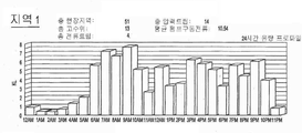
도 9a 및 도 9b는 다른 영역들의 다수의 설비들에서 측정된 유체 수위의 예시적인 보고이다.Embodiments will now be described in more detail by way of example only with reference to the accompanying drawings, in which:
1 is a schematic diagram of a pressure sewage system having a pump control system according to some embodiments.
2 is a schematic diagram of a pump control system.
3 is a schematic view of the electronic circuit of the pump control system.
4 is a schematic diagram of a pressure type sewage network monitoring system according to some embodiments.
Figure 5 is an exemplary user interface display generated by the interface components of a pressurized sewage network monitoring system.
Figure 6 is an exemplary plot of fluid level in a fluid vessel of one pressure sewer system over time.
Figure 7 is another exemplary user interface display generated by the interface elements of a pressurized sewage network monitoring system.
Figure 8 is another exemplary user interface display generated by an interface component of a pressurized sewage network monitoring system.
Figures 9a and 9b are exemplary reports of fluid levels measured at multiple facilities of different areas.
상술한 실시예들은 일반적으로 압력식 하수 시스템 및 이런 시스템 또는 이런 시스템에서 펌프와 같은 구성요소의 모니터링 및 제어에 관한 것이다. 몇몇 실시예에서는 특히 압력시 하수설비용 펌프제어 시스템에 관한 것인 반면, 다른 실시예는 상술한 펌프제어 시스템을 포함한 압력식 하수설비 네트워크를 모니터링하기 위한 시스템에 관한 것이다. 다른 실시예들은 펌프제어 시스템을 포함한 압력식 하수설비 또는 이들에 대한 키트에 관한 것이다.The embodiments described above generally relate to the monitoring and control of pressure sewer systems and components such as pumps in such systems or systems. While some embodiments relate specifically to a pump control system for a sewage system at the time of pressure, another embodiment relates to a system for monitoring a pressure sewer system network including the pump control system described above. Other embodiments relate to a pressure sewer system including a pump control system or a kit therefor.
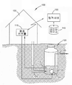
특히 도 1, 2, 및 3을 참고하면, 매립식 하수도 탱크(120)와 협력해 동작하는 펌프제어 시스템(110)을 포함한 압력식 하수설비(100)가 도시되어 있다. 하수도 탱크(120)가 지하부분을 구성하는 반면에 펌프제어 시스템(110)은 설비(100)의 지상부분을 구성한다. 하수도 탱크(120)는 유입도관(126)을 통해 거주지 또는 다른 건물(102)로부터 오수를 받도록 정해진 유체 저수장(122)이 있다. 유체 저수장(122)은 내부에 펌프(124)가 있고, 상기 펌프(124)는 저수장(122) 밖으로 유체를 펌프해 유체 유입도관(128)을 통해 유체도관의 망상 하수네트워크로 내보내게 되어 있다. 1, 2, and 3, there is shown a pressurized
설비(100)의 지하 구성요소들은 또한 수위센서(112) 및 플로트 스위치(212)를 포함한다. 수위센서(112)는 가령 압력 트랜스듀서일 수 있고 전기 케이블과 같은 적절한 수단을 통해 펌프제어 시스템(110)과 전기연결된다. 펌프(124)는 펌프제어 시스템(110)의 제어하에서, 주 전력을 메인 전원(248)으로부터 펌프(124)로 공급하는 적절한 펌프 컨택터(릴레이)(224)의 작동에 응답해 단지 온오프로 동작한다. The underground components of the
수위센서(112)는 일반적으로 유체 저수장(122) 내 유체 수위의 상시 정확한 측정을 얻고 상시(또는 유효하게 끊임없이 충분히 규칙적인) 출력신호를 펌프제어 시스템(110)에 제공하기 위해 유체 수위 아래에 잠겨 있다. 플로트 스위치(212)는 고수위 페일 세이프(fail safe)로 제공되므로, 저수장(122)의 유체 수위가 플로트 스위치(212)의 셧오프 수위보다 높아지면, 플로트 스위치(212)는 유체수위 하이신호를 펌프제어 시스템(110)에 제공하며, 이로 인해 (이전에 그렇게 하지 않았다면) 펌프(124)가 유체를 저수장(122) 밖으로 펌프하도록 개시하게 한다.The
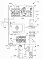
펌프제어 시스템(110)은 설비(100)의 지상부분이고, 거주지(102) 거주민 또는 보수직원이 쉽게 접근하기 위한 벽 또는 다른 곳에 위치될 수 있다. 펌프제어 시스템(110)은 비인가자에 대해 폐쇄되고 잠겨진 하우징(202)이 있다. 하우징(202)은 시각경보 표시기(203) 및 청각경보기(204)가 있어 장애가 발생했거나 발생하고 있음을 거주민에게 나타낸다. 무음버튼(205)이 하우징(202)의 외부에 위치될 수 있고 청각경보기(204)를 조용히 시키도록 작동될 수 있다. The
펌프제어 시스템(110)은 컨트롤러(208), 무선 트랜시버 유닛(210), 가령 배터리(215) 형태의 백업 전원, 펌프(124)의 동작을 제어하기 위한 릴레이(224) 및 전기 공급 및 제어 블록(240)이 있다. 펌프제어 시스템(110)은 또한 하나 이상의 유무선 트랜시버 또는 수신기(미도시)가 있을 수 있다. 하나 이상의 유량계 및/또는 수도, 전기 또는 기타 공사(公社)와 관련된 기타 계기들(미도시)이 또한 시스템(100)의 일부를 형성하고 하나 이상의 추가 유무선 트랜시버 또는 수신기와 소통할 수 있다. 컨트롤러(208)는 메모리(미도시) 및 상기 메모리에 저장된 프로그램 명령어를 실행하도록 구성된 적어도 하나의 프로세서(반짝거리게 도시됨)를 구비한다. 펌프 및 무선 트랜시버 유닛(210)의 동작을 위해 수 많은 세트 포인트들과 제어 파라미터들이 메모리에 또한 저장된다. The
컨트롤러(208)는 가령 표준 GSM 모바일 텔레포니 프로토콜을 이용한 무선통신 기반시설을 통해 원격 서버(130)와 트랜시버 유닛(210)을 통한 양방향 통신이 가능하다. 컨트롤러(208)는 저전력 무선 통신 프로토콜, 가령 블루투스 또는 IEEE 802.11 프로토콜, 또는 유선 통신 프로토콜을 통해 (있다면) 추가 트랜시버 또는 수신기 유닛을 통해, 유량계 또는 기타 계기들(미도시)과 같은 외부 디바이스들과 일방향 또는 양방향 통신이 가능할 수 있다. 이런 식으로, 컨트롤러 및 트랜시버/수신기는 시스템(100)과 관련된 다수의 로컬 계기들 또는 디바이스들의 통신 및 제어를 하기 위한 전체적 또는 부분적 무선허브로서 작동할 수 있다. 트랜시버 유닛(210)은 하우징(202)내에 감추어진 송수신 안테나(211)가 있다. 하우징(202)은 하우징(202) 안밖으로 충분한 신호전송강도를 가능하게 하기 위해 적절한 비전도성 재료로 형성된다. The
컨트롤러(208)는 기설정된 양, 가령, 수 밀리미터 또는 퍼센트 양씩 변할 때, 측정된 유체수위 데이터를 메모리에 저장한다. 마찬가지로, 다른 측정된 파라미터들 또는 동작 상태들도 이들이 변할 때 컨트롤러의 메모리에 기록되고 이들이 발생할 때의 당시로 타임스탬프된다. 이 저장된 데이터는 그런 후 트랜시버 유닛(210)을 통해 서버(130)로 매 1, 2, 4, 6, 8, 12 또는 24 시간과 같이 주기적으로 또는 서버(130)의 요구시 업로드된다. The
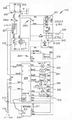
펌프제어 시스템(110)에 대한 개략적 레이아웃 및 전기도면이 도 2 및 도 3에 도시되어 있다. 펌프제어 시스템(110)의 구성요소들의 물리적 및 전기적 레이아웃을 이해하기 위해 이들 두 도면들은 서로 결부해 해석되어야 한다. A schematic layout and electrical diagram for the
배터리(215)는 주 전원(248)에서 받은 전력 레벨의 손실 또는 상당한 강하 동안 통신능력을 유지하기 위한 컨트롤러(208) 및 트랜시버 유닛(210)용 백업 전원을 제공한다. 입력 전류 및 전압을 감지하기 위해 전류센서(221) 및 전압감지 릴레이(241)가 메인 스위치(246)를 통해 주 전원(248)에 연결된다. 전류센서(221) 및 전압감지 릴레이(241)는 이들의 출력을 컨트롤러(208)에 제공해 상기 컨트롤러(208)가 입력 전원레벨을 모니터하고 필요하다면 펌프(124)의 동작을 중단시킬 수 있다. 전원 입력블록(240)은 또한 제 1 및 제 2 회로 브레이커(245a,245b)와 DC 전원 트랜스포머(242)를 포함한다. 주 전원에서 스파이크의 경우에, 퓨즈(244)가 또한 제공된다. DC 전원(242)은 배터리(215)를 충전시킨다. 컨트롤러(208)가 펌프 릴레이(224)를 제어하도록 하기 위해 12 VDC 컨트롤 릴레이(247)가 제공된다. The
수동 스위치가 자동위치에 있을 경우 펌프 릴레이(224)가 컨트롤러(208)로부터의 제어신호에 응답해 동작된다. 수동 스위치(243)가 오프 위치에 있으면, 릴레이(224)는 개방되고 펌프(124)는 전력을 받지 않는다. 수동 스위치(243)가 수동 위치에 있으면, 릴레이(224)는 폐쇄되고 펌프는 컨트롤러(208)로부터의 제어와 무관하게 주 전력을 받는다. 릴레이(224)는 적절한 방식으로 지면 및 유체 저수장(122)으로 뻗어 있는 적절한 전력 케이블(225)을 통해 펌프(124)에 주 전력을 제공한다.When the manual switch is in the automatic position, the
유체수위 트랜스듀서(112)는 컨트롤러(208)가 전기연결된 연결블록(214)에 결합된 출력 도체(213)가 있다. 플로트 스위치(212)의 출력부가 이 연결블록(214)에 또한 결합되어 있어, 컨트롤러(208)가 플로트 스위치(212)로부터 온오프 상태 신호를 수신한다.The
컨트롤러(208)는 프로그래머블 로직 컨트롤러(PLC)로서 효과적으로 기능하는 직렬통신 및 데이터 획득(SCADA) 유닛의 형태를 포함하거나 그 형태일 수 있다. 컨트롤러(208)는 트랜시버 유닛(210)과 적절한 직렬 데이터연결을 갖는다. 컨트롤러(208)는 가령 컨트롤 마이크로시스템으로부터 적절한 DNP3 SCADA 팩(100) 컨트롤러이거나 이를 포함할 수 있다. 다른 컨트롤러들이 시스템(100)에 사용될 수 있고 본 명세서에 기술된 컨트롤러(208)의 기능을 수행하기 위한 DNP3 통신 프로토콜 또는 또 다른 적절한 통신 프로토콜을 이용할 수 있다.The
트랜시버 유닛(210)은 가령 NetComm NTC-6908 산업용 3G 셀룰러 네트워크 라우터일 수 있다. 따라서, 트랜시버 유닛(210)은 원격 서버(130)와 적절히 인터페이스하도록 일대일(point-to-point) 또는 일대다(point-to-multi-point) 통신 능력을 제공할 수 있다. 트랜시버 유닛(210)은 적절한 도메인 영역 시스템(DNS) 능력을 이용할 수 있어 트랜시버 유닛(210)내 임의의 가입자식별모듈(SIM)이 이런 또 다른 SIM과 상호교환될 수 있다.The
컨트롤러(208)에 대한 디지털 및 아날로그 입출력은 일반적으로 다음과 같다:The digital and analog inputs and outputs for the
컨트롤러 이진 입력:Controller binary input:
BI-1 : 비상 고수위 플로트 스위치; BI-1: Emergency high float switch;
BI-2: 현장 주 전력 고장 경보; BI-2: Field main power failure alarm;
BI-3: 펌프 실행 명령상태.BI-3: Pump run command status.
컨트롤러 이진 출력: Controller binary output:
BO-1: 컨트롤러(208)로부터 펌프 저지신호.BO-1: Pump stop signal from
컨트롤러 아날로그 입력: Controller analog input:
AI-1 : 수위센서(112)로부터 우물 수위; AI-1: Well level from the
AI-2: 펌프 전류; AI-2: pump current;
AI-3: 펌프개시수위 SP(상태); AI-3: pump-initiated water level SP (state);
AI-3: 펌프중지수위 SP (상태).AI-3: Pump stop level SP (status).
컨트롤러 아날로그 출력: Controller analog output:
AO-1 : (서버(130)로부터) 펌프개시수위 SP ; AO-1: (from server 130) pump start level SP;
AO-2: (서버(130)로부터) 펌프중지수위 SP.AO-2: (from server 130) Pump Stop Level SP.
컨트롤러(208)의 동작은 다음 용어로 더 특징될 수 있다:The operation of the
동작action
펌프(124)는 탱크(122)내 감지된 유체수위가 펌프개시 세트포인트 이상이면 실행되고 탱크(122)내 감지된 유체수위가 펌프개시 세트포인트 이하이면 중지된다. 펌프개시수위 세트포인트(AO-1) 및 펌프중지수위 세트포인트(AO-2)는 컨트롤러(208)의 물리적 출력이 아니다. 오히려, 이들은 서버(130)에 실행되고 (또는 서버에 의해 제공되고) 서버(130)에 의해 호스팅된 적절한 컴퓨터화된 사용자 인터페이스를 통해 인가자에 접속될 수 있는 소프트웨어 구성 툴(430)을 이용해 모두 설정된다. 클라이언트 디바이스(420,425)의 사용자가 체험하는 사용자 인터페이스는 , 예컨대, 시스템(400)에서 하나 이상의 클라이언트 컴퓨팅 디바이스들(420,425)을 실행하는 브라우저 애플리케이션(440)에 의해 제공될 수 있다. 일단 선택되면, 펌프개시수위 세트포인트 및 펌프중지수위 세트포인트가 데이터 스토어(140)에 저장되고 서버(130)에 의해 선택된 세트포인트가 적용되는 각각의 설비(100)의 트랜시버 유닛(210) 및 컨트롤러(208)로 전송된다. The
감지된 유체수위가 정상개시수위 너머의 점에 있다면 펌프(124)를 개시하고 경보를 설정하기 위해 고수위 아날로그 세트포인트가 또한 포함될 수 있다. 플로트/비상 고수위 신호(BI-1)가 활성화되면, 펌프(124)는 신호 입력이 (클라이언트 컴퓨팅 디바이스(420,425)를 통해 접속가능한 사용자 인터페이스를 통해 설정된) 기설정된 시간 동안 낮아질 때까지 실행하도록 강제할 것이다. 컨트롤러(208)는 펌프(124)를 설정시간(디폴트로 8시간) 동안 디스에이블시킬 수 있다. A high level analog setpoint may also be included to initiate the
컨트롤러(208)는 (분출모드에서) 특정시간 때까지 개시수위 세트포인트 및 고수위 세트포인트 사이로 펌프(124)를 실행하도록 개시수위 세트포인트를 조절하기 위해 구성 툴(430)로부터의 명령을 수신하고 응답할 수 있어, 정상보다 큰 유체량이 저수장(120)으로부터 내려보내질 수 있다. The
디지털 입력Digital input
플로트/비상 고수위Float / Emergency high water level
(전압 모니터 릴레이로부터) 전력상태 OK(From voltage monitor relay) Power status OK
고압 입력High pressure input
경보 무음 푸시버튼Alarm silent push button
아날로그 입력Analog input
프로브 수위 (4-20 ma)Probe level (4-20 mA)
펌프 전류 -CT (4-20 ma)Pump current - CT (4-20 ma)
디지털 출력Digital output
(모터 컨택터로) 모터 구동(To motor contactor) Motor driven
경적(경적에서 5분 후 자동 무음)Horn (silent after 5 min in horn)
경보등(경고에 따라 다른 플래시)Alarm light (different flash depending on warning)
(경보가 그칠 때까지) 스트로브 플래셔(Until alarm stops) Strobe flasher
SCADA 디스플레이(사용자 인터페이스에 의해 클라이언트 디바이스(420,425)에 제공됨) SCADA display (provided to the
펌프 실행Pump run
펌프 고장Pump failure
펌프 구동전류Pump drive current
수위Water level
모든 경보All alarms
모든 세트 포인트All Set Points
시간 세트포인트 강제 오프Time set point forced off
경보(PLC 전원 사이클에 경보 해소 또는 상태 해소) Alarm (Alarm is released or released in the PLC power cycle)
램프 작동 경보Lamp operation alarm
램프 이중 플래시 펌프 고장Lamp double flash pump failure
설정 시간주기 동안 고전류가 검출되면, 10분간 펌프를 중지시킨다. 펌프가 연이어 10회(또는 또 다른 구성가능한 횟수) 중지되면, 펌프를 잠근다. 펌프 경보가 계속 작동된다.If a high current is detected during the set time period, the pump is stopped for 10 minutes. When the pump is stopped 10 times (or another configurable number of times), the pump is locked. The pump alarm continues to operate.
램프 작동 경보Lamp operation alarm
램프 3연속 플래시 펌프 고압
설정시간에 고압이 검출되면, 10분간 펌프를 중지시킨다; 펌프가 연속으로 10회 중지되면, 펌프를 잠근다.If high pressure is detected at set time, stop pump for 10 minutes; If the pump stops 10 times in a row, lock the pump.
펌프 작동 경보Pump operation alarm
램프 온 비상 고수위Lamp on Emergency high water level
플로트 스위치를 트리핑하는 하이 플로트(high float) 상태의 검출시, 램프/경적을 활성화시키고 서버(130)에 통지하고, 서버는 사용자 인터페이스(430)를 통해 상태를 나타낸다.Upon detection of a high float condition that trips the float switch, the lamp / horn is activated and notified to the
일반적으로, 램프 스트로브와 경적은 경보 발생으로부터 기설정된 시간 지연 후에 활성화되고, 별도의 (더 짧은) 시간 값 후에 예상 리포트가 원격 서버(130)로 보내진다. 스트로브와 경적 활성화 및 예상 리포트 전송 간의 시간차는 18시간까지 일 수 있다. 이는 원격진단이 실행되게 하고 경보의 활성화에 의해 주민에 문제가 통보되기 전에 명백한 문제를 접근 및 조정하도록 담당 공사기관이 시간을 갖게 한다.Generally, the lamp strobe and horn are activated after a predetermined time delay from the alarm occurrence, and a predicted report is sent to the
세트 포인트Set point
펌프중지수위Pump stop level
펌프개시수위Pump-initiated water level
펌프 고수위Pump high water level
펌프 고전류Pump high current
펌프 구동 없음/ 저전류No pump drive / low current
장기간 펌프 구동Long-term pump drive
타이머 상에 펌프 비상 고수위 구동Emergency pump high-level drive on timer
펌프 디스에이블 타이머 Pump Disable Timer
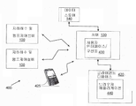
도 4를 참조하면, 다수의 설비들(100)을 구비한 압력식 오수 모니터링 시스템(400)이 더 상세히 설명되어 있다. 압력식 하수 모니터링 시스템(400)은 하나 이상의 하수 네트워크 지역들에 걸쳐 다른 지리적 위치한 다수의 설비들(100)을 포함한다. 다수의 설비들(100)은 대형 하수 네트워크 내의 한 지역의 일부일 수 있거나 다른 지역 및/또는 다른 네트워크를 가로질러 분포될 수 있다. 단지 예로써, 각 지역은 지역내 다른 위치들에 있는 1, 2, 3, 4, 5, 6, 7, 8, 9, 10개 이상의 설비들(100)이 있을 수 있다. 또한, 10개 이상, 가령 특정 하수지역 및/또는 네트워크 내에 10개 내지 가능하게는 수백 개의 이런 설비들(100)이 있을 수 있다. 예로써, 도 8은 대형 서비스 지역(810)의 일부 내에 위치해 있고 클라이언트 디바이스 상의 맵 디스플레이(800)에 관계해 볼 수 있는 6개의 별개의 지역들(812a, 812b, 812c, 812d, 812e 및 812f로 표시됨)을 도시하고 있다. 각 지역(812)은 내부에 위치된 하나 이상의 설비들(100)이 있다.Referring to FIG. 4, a pressure
유체 모니터링 시스템(400)은 편의상 본 명세서에서 서버(130)로 언급된 하나 이상의 서버들 또는 서버 시스템들, 적어도 하나의 유선 클라이언트 디바이스(420) 및/또는 적어도 하나의 모바일 클라이언트 디바이스(425) 및 데이터 스토어(140)을 더 구비한다. 서버(130)는 펌프(124)의 감지된 상태들을 나타내는 설비(100)로부터의 데이터 및/또는 다양한 다른 위치들에서 유체 저수장(122)내 유체 수위를 수신하도록 갖추어져 있다. 이 데이터는 휴대전화 네트워크와 같이 적어도 부분적으로 무선인 적절한 통신 기반시설(미도시)을 포함한 데이터 네트워크를 통해 수신된다. 예컨대, 설비(100)의 트랜시버 유닛(210)은 모바일 텔레포니 또는 이들의 기술적 계승에 대한 GSM 또는 GPRS/3G 표준을 이용해 데이터를 서버(130)로 전송하도록 구성될 수 있다. 대안으로, 가령 인근 설비(100) 내에서 트랜시버 유닛(120)과 무선 통신을 지원하기 위해 로컬 무선 데이터 허브가 충분히 가까이 있을 경우, 저전력, 단거리 무선 통신기술이 이용될 수 있다. 몇몇 실시예에서, 트랜시버 유닛(210)은 시스템(100) 바로 부근에서 계량 또는 감지 계기들와 같은 다른 디바이스들에 대한 로컬 무선 데이터 허브로서 작동할 수 있다. The
서버(130)는 트랜시버 유닛(210)으로부터 수신된 데이터를 처리하고 필요에 따라 연이은 검색을 위해 이를 데이터 스토어(140)에 저장한다. 데이터 스토어(140)는 로컬, 외부, 분산 또는 별개의 데이터베이스와 같은 임의의 적절한 데이터 스토어를 구비할 수 있다. 설비(100)로부터 서버(130)에 수신된 데이터가 하나 이상의 설비(100) 중 어느 하나에서 경보 상태를 나타내면, 서버(130)는 데이터 스토어(140)에 접속해 특정 경보상태와 관련해 취해질 기설정된 적절한 행동을 판단하고, 그런 후 적절한 행동을 취한다. 취해지는 행동은 가령 몇몇 설비들(100)이 다른 설비들보다 더 중요한 모니터링 역할을 할 수 있다면 설비(100)에 따라 다를 수 있다. 이런 행동은 가령 문자 메시지 및/또는 이메일 형태로 하나 이상의 통지를 하나 이상의 클라이언트 디바이스(420,425)로 전송하는 단계를 포함할 수 있다. The
설비(100)로부터 서버(130)에 수신된 데이터에 의해 경보 상태가 표시되는지 여부에 무관하게, 상기 데이터는 처리되고 클라이언트 디바이스(420,425)로부터 서버 프로세스 및/또는 요청에 의한 추후 검색을 위해 데이터 스토어(140)에 저장된다. 예컨대, 서버(130)는 하나 이상의 클라이언트 디바이스(420,425)로 기능의 트렌딩 및 리포팅을 수행하도록 (가령, 데이터 스토어(140)에 또는 서버(130)에 로컬인 메모리에 저장된 프로그램 코드를 기반으로 한) 프로세스를 실행할 수 있다. 예컨대, 서버(130)는 이런 정보에 대한 요청에 응답해 또는 자동적으로 규칙적인 간격으로 클라이언트 디바이스(420 또는 425)에서 브라우저 애플리케이션(440)을 통해 디스플레이(500, 600, 700 또는 800)(각각 도 5, 6, 7 또는 8)의 발생을 가능하게 하도록 클라이언트 디바이스(420)에 정보를 제공될 수 있다. 디스플레이(500)는 시간 주기에 걸쳐 다른 위치들에서 압력식 하수설비(100)의 하나 이상의 동작 상태들에 대한 히스토리 및 현재 데이터를 도표로 만들 수 있다. 예컨대, 도 5에 도시된 바와 같이 디스플레이(500)는 시간 주기에 걸쳐 특정한 압력식 하수설비(100)에서 유체 수위의 차트(540)를 뿐만 아니라 설비(100)의 많은 동작 파라미터들에 대한 디스플레이 상태 정보(530)를 포함할 수 있다. Regardless of whether the alert state is indicated by the data received from the
서버(130)는 로컬적으로 액세스 가능한 저장된 프로그램 코드를 기반으로 사용자 인터페이스(430)를 실행해 클라이언트 디바이스(420,425)의 사용자가 구성, 제어, 모니터링, 및 설비(100)에 대한 서버(130)의 리포트 기능에 액세스하게 한다. 따라서, 사용자 인터페이스(430)는 클라이언트 디바이스(420,425)의 사용자에 액세스가능한 제어 및 구성 툴로서 작동한다. 사용자 인터페이스, 제어 및 사용자 인터페이스(430)의 구성 기능들은 주로 서버(130)에 의해 실행되나, 몇몇 기능들은 예컨대 서버(130)로부터 각각의 클라이언트 디바이스(420,425)에 이용되는, 가령, 애플릿을 포함한 코드를 기반으로 클라이언트 디바이스(420,425)상의 브라우저 애플리케이션(440)에 의해 부분적으로 실행될 수 있다. The
대안적인 실시예에서, 브라우저 애플리이션(440) 대신, 각 클라이언트 디바이스(420,425)는 디바이스의 프로세서에 액세스할 수 있는 로컬 메모리에 저장된 특수 소프트웨어 애플리케이션을 실행할 수 있다. 이 특수 애플리케이션은 로컬적으로 다양한 사용자 인터페이스 기능들 수행할 수 있고 필요에 따라 서버(130)와 소통할 수 있다. 예컨대, 모바일 클라이언트 컴퓨팅 디바이스(425)에 대해, 특수 애플리케이션은 "스마트폰" 애플리케이션 형태일 수 있다.In an alternative embodiment, instead of
도 5, 6, 7, 및 8에 도시된 디스플레이(500, 600, 700, 및 800)는 각각 프로세서에 액세스가능한 로컬 스토리지에 저장된 프로그램 코드에 따라 클라이언트 디바이스(420,425)의 프로세서에 의한 실행시 브라우저 애플리케이션(440)과 같이 클라이언트 디바이스(420,425) 상에 실행되는 적절한 소프트웨어 애플리케이션에 의해 클라이언트 디바이스(420,425)에서 발생될 수 있다. The
바람직한 실시예에서, 트랜시버 유닛(120)은 서버(130)와 양방향 소통을 위해 인에이블되므로, 새로운 유체 수위 임계치가 설정, 제어명령이 발행, 펌웨어 업데이트가 수신 및/또는 진단 모니터링 및 테스트이 원격으로 수행될 수 있다.In a preferred embodiment, the
따라서, 압력식 하수 모니터링 시스템(400)은 동작 상태가 모니터되는 것이 바람직한 영역 또는 지역 주위에 위치된 일련의 설비들(100)을 구비한다. 이들 설비들(100)은 서버(130)와 통신하고, 차례로 서버는 필요에 따라 클라이언트 디바이스(420,425)와 소통한다. 서버(130)는 또한 설비(100)로부터 수신된 히스토리 데이터를 추적 및 저장하고 소정의 기정의된 관심 이벤트들이 발생할 수 있는지 판단하기 위해 데이터 스토어(140)에 저장된 규칙에 따라 들어오는 히스토리 데이터를 처리한다. 이런 이벤트들은 복잡한 이벤트일 수 있고 이와 같이 저장된 규칙으로 정의될 수 있다. 선택적으로 특정 하수지역 또는 지역들을 최적으로 관리하기 위해, 예컨대, 홍수상황시스템(400)은 설비들(100)을 제어해 시간 주기동안 정상 자동동작을 중단하거나 고수위 세트포인트 아래로 동작하게 할 수 있다. Accordingly, the pressurized
시스템(400)에서, 각 설비(100)는 동작 파라미터들(즉, 경보수위, 센서 샘플링 시간, 리포팅 간격 등)의 동일하거나 유사한 세트를 갖도록 구성될 수 있고 동일한 센서(112,212) 세트 및 일반 구성을 가질 수 있다. In the
시스템(400)의 몇몇 실시예에서, 각 설비의 트랜시버 유닛(210)은 컨트롤러(208)에 의해 경보상황이라 판단되면 최종 사용자(즉, 클라이언트 디바이스(420,425))의 모바일 통신 디바이스에 직접 메시지를 보내도록 구성될 수 있다. 이는 서버(130)로 메시지를 보내는 것을 대신하거나 추가일 수 있다.In some embodiments of the
종래 압력식 하수 시스템에 대한 상술한 실시예들의 이점은 실질적으로 개선된 원격제어 및 모니터링 능력을 포함한다. 이는 모바일 텔레포니 표준 프로토콜의 이용에 의해 서버(130)와 각 펌프제어 시스템(110)의 컨트롤러(208) 간의 일대일 또는 일대다 통신을 용이하게 하도록 더 지원된다. 또한 많은 설비들(100)이 모니터되고 동일한 압력식 하수 시스템(400)의 일부로서 별개로 또는 함께 제어될 때 하수 네트워크 기반시설의 모니터링 및 최적 사용을 가능하게 하기 위해 정기적으로 각 수위센서(112)로부터 원격 서버(130)로 수위센서 출력을 제공하는데 있어 상당한 이점이 있다. 예컨대, 도 9a 및 도 9b에 도시된 바와 같은 사용 히스토그램이 다른 지역들에 얻어질 수 있다. Advantages of the above-described embodiments of conventional pressure type sewage systems include substantially improved remote control and monitoring capabilities. This is further supported to facilitate one-to-one or one-to-many communication between the
상술한 실시예들은 실시간 오수량을 계산하게 하며, 이는 계획 및 설계용도로 정확한 엔지니어링 데이터를 제공한다. 상술한 실시예들은 또한 하수 주처리 시설로 방출되는 피크량을 관리하기 위해 서버(130)로부터의 명령에 의한 펌프(124)의 원격제어로 이용될 수 있는 실시간으로 계산되는 오수량 모니터링을 가능하게 한다. 이는 시간에 걸쳐 하수 유량을 더 균일하게 분산시킬 수 있으며, 이는 처리 기반시설에 부담을 덜고 기반시설의 고장 위험을 줄일 수 있다. The embodiments described above allow for real-time sewage calculations, which provide accurate engineering data for planning and design purposes. The embodiments described above also enable the monitoring of the amount of waste water to be calculated in real time that can be used with remote control of the
상술한 실시예들에 대한 다른 이점들은 하나 이상의 설비들(100)로부터 누출 가능성을 유추하는 능력을 포함한다. 예컨대, 주어진 설비(100)에 대해, (분당 밀리미터와 같이)시간에 걸친 수위 변화량의 측정과 더불어 2.00 a.m 및 3.00 am 사이 시간과 같이 특정 주기동안 수위 변화 개수는 설비(100) 지역에서 누출 가능성을 나타낼 수 있다. 며칠에 걸쳐 그 주기 동안 유체수위의 일정한 증가는 작은 누출을 나타낼 수 있다. 따라서 보수직원이 지역에 파견되어 누출이 큰 문제가 되기 전에 조사할 수 있다. 그러므로, 상술한 실시예들은 압력식 하수 네트워크의 보수를 담당하는 곳들과 같은 기관들이 거주지(102) 주민들에 의한 불만으로 발전되기 전에 하나 이상의 설비들(100)이 갖는 문제들을 식별하고 해결하게 한다. Other advantages to the embodiments described above include the ability to deduce the likelihood of leakage from one or more of the
특히 도 5를 참조하면, 시스템(400)은 조작 보수직원이 각 설비(100)의 동작을 모니터하고 원격으로 제어하게 하는 사용자 인터레이스(430)를 실행할 적절한 소프트웨어 및 하드웨어 모듈을 포함한 능력을 구비한다. 도 5에서 디스플레이(500)는 서버로(130)로부터 이용되는 프로그램 코드 및/또는 데이터를 기반으로 브라우저 애플리케이션(440)에 의해 발생된 사용자 인터페이스 디스플레이의 일예이다. 디스플레이(500)는 LPS00013이라고 하는 특정 설비의 유체 저수장(122)의 그래픽 설명(510)을 갖는다. 유체 저수장(122)으로부터 유체를 펌프하도록 펌프(124)가 작동될 상부 유체수위 임계치 또는 세트포인트(가령, 400mm)의 표시와 함께 펌프(124)가 도면(510)에 또한 도시되어 있다. 상기 상부 유체 수위 임계치는 가령 브라우저 애플리케이션(440)을 통해 제어선택목록(520)에서 선택된 사용자 인터페이스(430) 및 적절한 소프트웨어 컨트롤 작동을 이용해 재구성될 수 있다. 마찬가지로, 이 경우 100mm로 도시된 하부 수위 임계치는 펌프(124)가 실행을 중단하도록 야기되는 수위일 수 있다. 제어선택목록(520)은 조작 직원이 관련된 컨트롤러(208)에 명령을 내림으로써 펌프(124)의 제어를 원격으로 취하거나 제어를 원격으로 해제하게 할 수 있다. 또한, 사용자 인터페이스의 상태 디스플레이(530)에 상태 정보가 제공된다. 이 상태 정보는 가령 펌프의 동작 모드를 바꾸거나 하나 이상의 세트 포인트들을 바꾸기 위해 허용가능한 경우 재구성될 수 있다.5, the
도 5에서 디스플레이(500)는 또한, 펌프가 짧은 주기에서 유체 수위를 최소(저수위 임계치)로 낮춘 후, 상부 유체 수위 임계치에 도달하는 지점까지 증가한 유체 수위를 나타내는 시간에 따른 유체수위 도표의 서브-디스플레이(540)를 갖는다. 이 도표(540)는 또한 펌프(124)의 고전류 소비 주기가 펌프 동작으로 인한 유체 수위의 감소와 상관되는 것을 검증하기 위해 시간에 걸쳐 펌프(124)에 의해 인출된 전류를 나타낼 수 있다. 이 도표(540)는 도 6에 더 상세히(확대해) 도시되어 있다. In FIG. 5, the
도 7은 특정 관심 설비(100)가 더 상세한 분석 또는 제어를 위해 선택될 수 있는 다수의 설비(100) 지역들의 목록(710)을 포함한 사용자 인터페이스의 다른 디스플레이(700)를 도시한 것이다. 도 7에 도시된 사용자 인터페이스에서, 소정의 선택가능한 제어기능들(720)이 도시되어 있다. 예컨대, 조작 직원은 컨트롤러(208)가 마지막 주기 이후로 메모리에 축적되고 저장된 기록 데이터 모두를 업로드하도록(통상 24시간 여론조사 주기를 기다리기보다는) 특정 설비(100)의 컨트롤러(208)의 서버(130)에 의한 즉각적 데이터 여론조사를 강요할 수 있다. 또한, 펌프(124) 또는 컨트롤러(208)의 펌프제어기능의 동작을 억제시키기 위한 선택가능한 옵션들이 제공된다. 또한, 도 7에 도시된 (브라우저 애플리케이션(440)을 통해 나타난) 사용자 인터페이스는 새로운 설비들이 설치되었을 때 목록(732)으로부터 상기 설비들이 라이브 네트워크에 추가되게 한다. 추가로, 설비가 계류중인 지역의 목록(740)이 제공될 수 있다. 목록(732)의 편집을 가능하게 하기 위해 컨트롤 버튼(735)이 제공되고 목록(740)의 편집을 가능하게 하기 위해 컨트롤 버튼(745)이 제공된다. 설비(100)의 모든 전력 장애의 히스토리를 보는 능력과 같은 다른 리포트 및 디스플레이들도 선택될 수 있다. FIG. 7 illustrates another
도 7에 도시된 사용자 인터페이스로부터 명백한 바와 같이, 서버(130)는 이런 각 설비에 대한 히스토리 조작 데이터와 함께 데이터 스토어(140)에서 각 설비(100)의 포괄적 데이터 기록을 유지한다. 얼마나 많은 데이터 스토리지가 가용하고/가용하거나 얼마나 많은 히스토리 데이터가 필요한 모니터링 및 제어 기능을 달성하는데 유용한 것으로 여겨지는지에 따라 히스토리 데이터의 시간 길이가 구성될 수 있다. 저장된 히스토리 데이터는 히스토리적으로 관련없는 정보를 저장하는 것을 방지하기 위해 필요에 따라 주기적으로 압축될 수 있다. As is apparent from the user interface shown in FIG. 7, the
실시예들은 다양한 가능한 특징 및 기능들과 관련해 예로써 본 명세서에 기술되었다. 이런 실시예들은 제한이라기보다 예시적인 것으로 의도되어 있다. 실시예들은 이런 특징들이 이같은 조합 또는 서브조합으로 명백히 기술되지 않더라도 본 명세서에 기술된 특징들의 다양한 조합 및 서브조합을 포함하는 것으로 이해되어야 한다. The embodiments have been described herein by way of example with reference to various possible features and functions. These embodiments are intended to be illustrative rather than limiting. The embodiments are to be understood as including various combinations and subcombinations of the features described herein even if these features are not explicitly stated as such combinations or subcombinations.
Claims (16)
컨트롤러에 액세스 가능하고 압력식 하수설비의 동작에 관한 동작 정보를 저장하도록 갖추어진 메모리; 및
컨트롤러가 통신 네트워크를 통해 원격 서버와 통신하게 하도록 컨트롤러와 소통하는 무선 트랜시버를 구비하고,
상기 컨트롤러는 압력식 하수설비의 유체 저수장에 있는 센서로부터 출력신호를 수신하도록 갖추어지고, 상기 출력신호는 유체 저수장에서 측정된 유체수위를 나타내는 압력식 하수설비용 펌프제어 시스템.A controller equipped to control the power supply to the pump of the pressure sewage system;
A memory accessible to the controller and adapted to store operation information regarding the operation of the pressurized sewage system; And
And a wireless transceiver in communication with the controller to allow the controller to communicate with the remote server via the communications network,
Wherein the controller is adapted to receive an output signal from a sensor at a fluid low water level of a pressurized sewage system, the output signal representing a fluid level measured at a fluid low water bed.
컨트롤러는 압력식 하수설비의 동작을 제어 및 모니터하고 저장된 동작 정보를 원격 서버로 보내도록 구성되는 압력식 하수설비용 펌프제어 시스템.The method according to claim 1,
Wherein the controller is configured to control and monitor the operation of the pressurized sewage system and to send the stored operational information to a remote server.
동작 정보는 측정된 유체 수위 정보를 포함하는 압력식 하수설비용 펌프제어 시스템.3. The method of claim 2,
Wherein the operation information includes measured fluid level information.
컨트롤러는 유체수위를 컨트롤러의 메모리에 저장된 유체수위 임계치와 비교하고 유체수위가 유체수위 임계치 이상인 경우 펌프가 유체를 유체 저수장 밖으로 펌프하도록 동작하게 구성되는 압력식 하수설비용 펌프제어 시스템.4. The method according to any one of claims 1 to 3,
Wherein the controller is configured to compare the fluid level to a fluid level threshold stored in the memory of the controller and to operate the pump to pump the fluid out of the fluid low level if the fluid level is above the fluid level threshold.
컨트롤러는 원격 서버로부터 수신된 명령에 응답해 메모리에 변경된 유체수위 임계치를 저장하는 압력식 하수설비용 펌프제어 시스템.5. The method of claim 4,
Wherein the controller stores the modified fluid level threshold in memory in response to a command received from the remote server.
무선 트랜시버는 모바일 텔레포니 표준 프로토콜을 이용해 원격 서버와 소통하도록 구성되는 압력식 하수설비용 펌프제어 시스템.6. The method according to any one of claims 1 to 5,
The wireless transceiver is configured to communicate with a remote server using a mobile telephony standard protocol.
컨트롤러는 원격 서버로부터 수신된 명령에 의해 원격으로 제어될 수 있도록 구성되는 압력식 하수설비용 펌프제어 시스템.7. The method according to any one of claims 1 to 6,
Wherein the controller is configured to be remotely controllable by a command received from a remote server.
시스템은 주 전력으로 구동되고 적절한 주 전력이 없을 경우 컨트롤러 및 무선 트랜시버에 전력을 공급하기 위한 백업 전원을 구비하는 압력식 하수설비용 펌프제어 시스템.8. The method according to any one of claims 1 to 7,
The system includes a back-up power supply for powering the controller and the wireless transceiver, driven by the main power and, in the absence of appropriate main power, a pump control system for a pressurized sewage system.
컨트롤러는 고 유체수위를 나타내는 유체 저수장내 플로트 스위치로부터 플로트 스위치 출력신호를 수신하도록 더 구성되고, 컨트롤러는 플로트 스위치 출력신호에 응답해 펌프를 동작시키도록 구성되는 압력식 하수설비용 펌프제어 시스템.9. The method according to any one of claims 1 to 8,
The controller is further configured to receive a float switch output signal from a fluid storage float switch exhibiting a high fluid level, and wherein the controller is configured to operate the pump in response to the float switch output signal.
시스템은 컨트롤러와 소통하는 하나 이상의 추가 디바이스들 및 하나 이상의 유무선 트랜시버들 또는 수신기들을 더 구비해, 컨트롤러가 하나 이상의 추가 디바이스들과 소통하거나 하나 이상의 추가 디바이스들로부터 정보를 수신하게 하는 압력식 하수설비용 펌프제어 시스템.10. The method according to any one of claims 1 to 9,
The system may further comprise one or more additional devices in communication with the controller and one or more wired or wireless transceivers or receivers to enable the controller to communicate with one or more additional devices or to receive information from one or more additional devices Pump control system.
하나 이상의 추가 디바이스들은 하수 또는 수도 네트워크의 일부를 모니터링하기 위한 적어도 하나의 유량계 또는 기타 계기들을 포함하는 압력식 하수설비용 펌프제어 시스템.11. The method of claim 10,
Wherein the at least one additional device comprises at least one flow meter or other meter for monitoring a portion of the sewage or water network.
원격 서버는 상기 원격 서버로부터 각 펌프제어 시스템으로 하나 이상의 명령들의 전송에 의해 각 펌프제어 시스템으로부터 수신된 메시지를 기초로 각 압력식 하수설비의 동작을 모니터하고 각 펌프제어 시스템의 동작에 영향을 주도록 구성되는 압력식 하수 네트워크 모니터링 시스템.A plurality of pump control systems according to any one of claims 1 to 11; And a remote server in communication with a wireless transceiver of each pump control system,
The remote server monitors the operation of each pressure sewer system based on messages received from each pump control system by transmission of one or more commands from the remote server to each pump control system and controls the operation of each pump control system Consisting of a pressure type sewage network monitoring system.
각 펌프제어 시스템의 원격 사용자 컨트롤을 가능하게 하도록 원격 서버와 통신하는 컴퓨터화 사용자 인터페이스를 더 구비하는 압력식 하수 네트워크 모니터링 시스템.13. The method of claim 12,
Further comprising a computerized user interface for communicating with a remote server to enable remote user control of each pump control system.
원격 서버는 수신된 메시지를 기초로 경보상태를 판단하고 하나 이상의 경보 메시지들을 하나 이상의 사용자 수신기들에 자동으로 전송하도록 구성되며, 하나 이상의 경보 메시지들은 경보상태의 표시를 포함하는 압력식 하수 네트워크 모니터링 시스템.The method according to claim 12 or 13,
Wherein the remote server is configured to determine an alert condition based on the received message and to automatically transmit one or more alert messages to one or more user receivers, wherein the one or more alert messages include an indication of an alert condition, .
Applications Claiming Priority (3)
| Application Number | Priority Date | Filing Date | Title |
|---|---|---|---|
| AU2012901005 | 2012-03-14 | ||
| AU2012901005A AU2012901005A0 (en) | 2012-03-14 | Pressure sewer control system and method | |
| PCT/AU2012/000903 WO2013149281A1 (en) | 2012-03-14 | 2012-07-31 | Pressure sewer control system and method |
Publications (2)
| Publication Number | Publication Date |
|---|---|
| KR20140135151A true KR20140135151A (en) | 2014-11-25 |
| KR101948742B1 KR101948742B1 (en) | 2019-02-15 |
Family
ID=49299849
Family Applications (1)
| Application Number | Title | Priority Date | Filing Date |
|---|---|---|---|
| KR1020147021213A KR101948742B1 (en) | 2012-03-14 | 2012-07-31 | Pressure sewer control system and method |
Country Status (12)
| Country | Link |
|---|---|
| US (2) | US9869430B2 (en) |
| EP (2) | EP2663697B1 (en) |
| JP (1) | JP2015515558A (en) |
| KR (1) | KR101948742B1 (en) |
| CN (2) | CN105247144A (en) |
| AU (1) | AU2012318281B2 (en) |
| CA (1) | CA2821820C (en) |
| DK (1) | DK2663697T3 (en) |
| IN (1) | IN2014DN08381A (en) |
| MY (1) | MY168328A (en) |
| SG (1) | SG193892A1 (en) |
| WO (1) | WO2013149281A1 (en) |
Cited By (1)
| Publication number | Priority date | Publication date | Assignee | Title |
|---|---|---|---|---|
| KR20200031777A (en) * | 2018-09-17 | 2020-03-25 | 한재웅 | Water pump control system using real-time wireless communication |
Families Citing this family (33)
| Publication number | Priority date | Publication date | Assignee | Title |
|---|---|---|---|---|
| US9499412B1 (en) * | 2013-04-26 | 2016-11-22 | Jerry L. McKinney | Sparse data for small environmental systems and method |
| US10623473B2 (en) | 2010-07-29 | 2020-04-14 | Jerry L. McKinney | Wastewater use and monitoring system |
| CN105247144A (en) | 2012-03-14 | 2016-01-13 | 东南水务公司 | Pressure sewer control system and method |
| AU2014321130B2 (en) | 2013-09-10 | 2019-02-21 | South East Water Corporation | Reservoir control systems and methods |
| CN103470484A (en) * | 2013-09-16 | 2013-12-25 | 国家电网公司 | Remote controller of motor-pumped-well water pump |
| NZ630446A (en) | 2014-09-03 | 2015-02-27 | South East Water Corp | Monitoring systems and methods |
| TWM505546U (en) * | 2014-11-07 | 2015-07-21 | Ding Hwa Co Ltd | Improved pump control device |
| WO2016078686A1 (en) * | 2014-11-17 | 2016-05-26 | Grundfos Holding A/S | Method for authorising a handheld communication device access to a pump unit |
| US20170170979A1 (en) | 2015-12-15 | 2017-06-15 | Pentair Flow Technologies, Llc | Systems and Methods for Wireless Control and Monitoring of Residential Devices |
| US10711788B2 (en) | 2015-12-17 | 2020-07-14 | Wayne/Scott Fetzer Company | Integrated sump pump controller with status notifications |
| EP3408542A4 (en) * | 2016-01-27 | 2019-08-28 | South East Water Corporation | Methods and systems for controlling supply of power generated by a weather dependent power generator |
| DE102016005102A1 (en) | 2016-04-27 | 2017-11-02 | Wilo Se | Communication device, in particular for a centrifugal pump |
| CN106020257A (en) * | 2016-08-01 | 2016-10-12 | 大唐七台河发电有限责任公司 | Ash field water drainage control system |
| EP3526559B1 (en) * | 2016-10-13 | 2023-09-06 | South East Water Corporation | Vibration sensor for fluid leak detection |
| US10865787B2 (en) * | 2016-12-06 | 2020-12-15 | Pentair Flow Technologies, Llc | Connected pump system controller and method of use |
| EP3242035B1 (en) * | 2016-12-28 | 2021-08-18 | Grundfos Holding A/S | Method for operating at least one pump unit of a plurality of pump units |
| WO2018137116A1 (en) * | 2017-01-24 | 2018-08-02 | 深圳企管加企业服务有限公司 | Method and system for monitoring gas holder through internet of things |
| TWI624596B (en) * | 2017-03-15 | 2018-05-21 | 亞台富士精機股份有限公司 | Pump apparatus with remote monitoring function and pump apparatus monitoring system |
| USD893552S1 (en) | 2017-06-21 | 2020-08-18 | Wayne/Scott Fetzer Company | Pump components |
| CN107237387A (en) * | 2017-07-29 | 2017-10-10 | 安徽亿纵电子科技有限公司 | A kind of sewer blockage monitoring system |
| CN111247497B (en) * | 2017-11-07 | 2024-06-14 | 惠普发展公司,有限责任合伙企业 | Foam coalescing |
| CN108181870A (en) * | 2017-12-27 | 2018-06-19 | 上海熊猫机械(集团)有限公司 | A kind of long-range cruising inspection system of pump house and method |
| USD890211S1 (en) | 2018-01-11 | 2020-07-14 | Wayne/Scott Fetzer Company | Pump components |
| CN108412027A (en) * | 2018-03-08 | 2018-08-17 | 阜阳师范学院 | A kind of cable shaft intelligent drainage system based on Internet of Things |
| US20190301444A1 (en) * | 2018-03-30 | 2019-10-03 | Cole-Parmer Instrument Company Llc | Network monitoring and control of fluid handling apparatus |
| IT201900012879A1 (en) * | 2019-07-25 | 2021-01-25 | Dab Pumps Spa | DEVICE FOR DETECTION OF THE LEVEL OF A WELL / TANK AND IMMERSION ELECTRIC PUMP WITH THIS DEVICE |
| CN111140480A (en) * | 2019-12-05 | 2020-05-12 | 深圳市电王科技有限公司 | Automatic switching power supply and water supply control method and controller |
| CN111287296A (en) * | 2020-03-07 | 2020-06-16 | 叶建锋 | Method and device for intelligent operation of rainwater storage tank |
| US11134156B1 (en) | 2020-03-31 | 2021-09-28 | Saudi Arabian Oil Company | System and method for detecting and alerting of flooding in telecommunications manholes |
| WO2022087346A1 (en) * | 2020-10-23 | 2022-04-28 | Cornell Pump Company | Monitoring system for pump with mechanical seal lubrication arrangement |
| CN114326625B (en) * | 2021-12-28 | 2023-08-25 | 毕马智能科技(上海)有限公司 | Monitoring system and method for potential safety risk in power grid infrastructure construction |
| CN114753466B (en) * | 2022-03-01 | 2024-04-12 | 中国核电工程有限公司 | Lifting discharge system and method for special sewage collection and detection |
| CN116123456B (en) * | 2023-02-24 | 2023-09-26 | 贝滨(广东)科技有限公司 | Urban water supply pipe network monitoring system based on Internet |
Citations (1)
| Publication number | Priority date | Publication date | Assignee | Title |
|---|---|---|---|---|
| JP2011008627A (en) * | 2009-06-26 | 2011-01-13 | Kubota Corp | Facility information management system |
Family Cites Families (56)
| Publication number | Priority date | Publication date | Assignee | Title |
|---|---|---|---|---|
| US6378554B1 (en) * | 2000-01-14 | 2002-04-30 | Little Giant Pump Company | Controlled sewage sump network system |
| US6595051B1 (en) * | 2000-06-08 | 2003-07-22 | Chandler Systems, Inc. | Fluid level sensing and control system |
| US7072945B1 (en) * | 2000-06-30 | 2006-07-04 | Nokia Corporation | Network and method for controlling appliances |
| US6488853B1 (en) * | 2000-10-04 | 2002-12-03 | Great Circle Technologies, Inc. | Process and apparatus for treating wastewater |
| US6395181B1 (en) * | 2000-10-04 | 2002-05-28 | Great Circle Technologies, Inc. | Process and apparatus for treating wastewater |
| US6491828B1 (en) | 2000-11-07 | 2002-12-10 | General Electric Company | Method and system to remotely monitor groundwater treatment |
| US6638023B2 (en) * | 2001-01-05 | 2003-10-28 | Little Giant Pump Company | Method and system for adjusting operating parameters of computer controlled pumps |
| US7626508B2 (en) * | 2002-03-05 | 2009-12-01 | Aeromesh Corporation | Monitoring system and method |
| EP1343063A2 (en) * | 2002-03-06 | 2003-09-10 | Fuji Photo Film Co., Ltd. | Wastewater treatment control system, terminal, computer program and accounting method |
| US7342506B2 (en) | 2003-06-02 | 2008-03-11 | Hach Company | Wireless remote monitoring system |
| CN1290359C (en) * | 2003-06-20 | 2006-12-13 | 华为技术有限公司 | A remote control system and method thereof |
| US20050072469A1 (en) | 2003-10-02 | 2005-04-07 | Preul Herbert C. | Wastewater source control system |
| US7623028B2 (en) | 2004-05-27 | 2009-11-24 | Lawrence Kates | System and method for high-sensitivity sensor |
| US20060078435A1 (en) * | 2004-08-19 | 2006-04-13 | Metropolitan Industries | Pump monitoring system |
| US7325257B2 (en) | 2004-12-01 | 2008-02-05 | Kohler Co. | Control system for pump operated plumbing fixtures |
| US7289923B2 (en) | 2005-07-21 | 2007-10-30 | Nagare | System and method for fluid distribution |
| US7905245B2 (en) * | 2005-09-30 | 2011-03-15 | Siemens Water Technologies Corp. | Dosing control system and method |
| CN1848764A (en) * | 2005-12-22 | 2006-10-18 | 华为技术有限公司 | Server and network equipment long-distance management maintenance system and realizing method |
| JP2007257190A (en) | 2006-03-22 | 2007-10-04 | Toshiba Corp | Total monitoring diagnosis device |
| US8594851B1 (en) * | 2006-12-20 | 2013-11-26 | Data Flow Systems, Inc. | Wastewater collection flow management system and techniques |
| US8983667B2 (en) * | 2006-12-20 | 2015-03-17 | Data Flow Systems, Inc. | Fluid flow management through a wastewater level manipulation system and associated methods |
| US8600568B2 (en) * | 2006-12-20 | 2013-12-03 | Data Flow Systems, Inc. | Fluid flow management system and associated methods |
| CN101021725A (en) * | 2007-03-23 | 2007-08-22 | 陈金龙 | Sewage pump station monitoring system |
| US8074911B2 (en) * | 2007-05-14 | 2011-12-13 | Environment One Corporation | Wireless liquid level sensing assemblies and grinder pump assemblies employing the same |
| GB2451876A (en) * | 2007-08-15 | 2009-02-18 | Mono Pumps Ltd | Pump system for a pressure sewer system |
| AU2008217000B2 (en) * | 2007-09-21 | 2012-02-09 | Multitrode Pty Ltd | A pumping installation controller |
| DE102007053948A1 (en) * | 2007-11-09 | 2009-05-14 | Wilo Ag | Plant and method for controlling a liquid flow |
| CN101187215B (en) * | 2007-11-28 | 2010-12-08 | 烟台双嘉电子科技有限公司 | Full-automatic current limiting type negative pressure-free pipe network Pressure-superposed water supply equipment |
| AU2008229982B2 (en) * | 2008-01-23 | 2009-10-29 | Multitrode Pty Ltd | Remote Pumping Station Monitoring Method |
| US7799224B2 (en) * | 2008-01-30 | 2010-09-21 | Siemens Water Technologies Corp. | Wastewater treatment methods |
| CN101220606B (en) * | 2008-01-30 | 2010-11-17 | 北京交通大学 | Dual-control intelligent laminating water service system |
| CN201258267Y (en) | 2008-05-09 | 2009-06-17 | 青岛理工新环境技术开发有限公司 | Buried intelligent sewage pump station |
| CA2997878A1 (en) | 2008-10-27 | 2010-05-06 | Mueller International, Llc | Infrastructure monitoring system and method |
| DE202008014858U1 (en) * | 2008-11-06 | 2009-03-26 | Noah, Jörg | grease trap |
| JP2010203964A (en) * | 2009-03-04 | 2010-09-16 | Toshiba Corp | Monitoring control system of sewerage facility |
| KR100932027B1 (en) * | 2009-03-18 | 2009-12-15 | 김재천 | Proportional control injecting device |
| CN201496242U (en) | 2009-03-25 | 2010-06-02 | 烟台昱合环保科技有限公司 | Automatic remote control and energy saving system of cluster pump station |
| KR20120046193A (en) * | 2009-07-27 | 2012-05-09 | 터치센서 테크놀로지스, 엘엘씨 | Level sensing controller and method |
| US9139457B2 (en) * | 2009-09-22 | 2015-09-22 | Anue Water Technologies, Inc. | Waste water treatment systems and methods |
| US20110110792A1 (en) * | 2009-11-12 | 2011-05-12 | Joseph Kendall Mauro | Sensors and methods and apparatus relating to same |
| US8591147B2 (en) | 2009-11-20 | 2013-11-26 | Geosyntec Consultants, Inc. | Combined water storage and detention system and method of precipitation harvesting and management |
| CN101800766A (en) | 2009-12-30 | 2010-08-11 | 上海交通大学 | Remote monitoring system of industrial sewage treatment based on Web |
| FR2957409B1 (en) * | 2010-03-11 | 2012-08-31 | Air Liquide | ELECTRICITY GENERATING METHOD USING AN AIR GAS SEPARATION UNIT AND A COMBUSTION UNIT |
| US20110240535A1 (en) * | 2010-04-01 | 2011-10-06 | Pehrson Richard L | System for controlling fluid levels in a wastewater treatment biological reactor |
| US9100728B2 (en) | 2010-06-10 | 2015-08-04 | Hach Company | Server monitoring of flow and sampling apparatus and/or logger |
| US20110307106A1 (en) | 2010-06-14 | 2011-12-15 | Kevin Charles Dutt | Methods and Systems for Monitoring, Controlling, and Recording Performance of a Storm Water Runoff Network |
| US8608404B2 (en) | 2010-07-29 | 2013-12-17 | Douglas Steven Safreno | Smart sustainable agricultural/aquacultural system and methods |
| CN102374927A (en) * | 2010-08-24 | 2012-03-14 | 中芯国际集成电路制造(上海)有限公司 | Leakage detection device and detection method using same |
| NZ589998A (en) | 2010-10-12 | 2011-10-28 | Ghd Pty Ltd | A pump unit for a pressure sewerage system wherein the pump operates in predetermined time sequence |
| US20120194502A1 (en) * | 2011-02-01 | 2012-08-02 | Rockwell Automation Technologies, Inc. | Searchable catalog for externally defined graphic element (edge) definitions |
| CA2826638A1 (en) | 2011-02-09 | 2012-08-16 | Andrew FORSTER-KNIGHT | Wirelessly networked fluid monitoring method, system and apparatus |
| AU2014100179B4 (en) * | 2012-03-14 | 2014-07-03 | South East Water Corporation | Pressure sewer control system and method |
| CN105247144A (en) * | 2012-03-14 | 2016-01-13 | 东南水务公司 | Pressure sewer control system and method |
| JP5769266B2 (en) | 2013-01-21 | 2015-08-26 | 学校法人金井学園 | Urban flood mitigation system |
| AU2014321130B2 (en) | 2013-09-10 | 2019-02-21 | South East Water Corporation | Reservoir control systems and methods |
| NZ630446A (en) | 2014-09-03 | 2015-02-27 | South East Water Corp | Monitoring systems and methods |
-
2012
- 2012-07-31 CN CN201280071396.8A patent/CN105247144A/en active Pending
- 2012-07-31 CN CN201810777717.5A patent/CN109002065B/en active Active
- 2012-07-31 AU AU2012318281A patent/AU2012318281B2/en active Active
- 2012-07-31 MY MYPI2014002322A patent/MY168328A/en unknown
- 2012-07-31 CA CA2821820A patent/CA2821820C/en active Active
- 2012-07-31 IN IN8381DEN2014 patent/IN2014DN08381A/en unknown
- 2012-07-31 JP JP2014561231A patent/JP2015515558A/en active Pending
- 2012-07-31 EP EP12865548.7A patent/EP2663697B1/en active Active
- 2012-07-31 WO PCT/AU2012/000903 patent/WO2013149281A1/en active Application Filing
- 2012-07-31 EP EP21153428.4A patent/EP3910121A1/en active Pending
- 2012-07-31 SG SG2013059225A patent/SG193892A1/en unknown
- 2012-07-31 KR KR1020147021213A patent/KR101948742B1/en active IP Right Grant
- 2012-07-31 DK DK12865548.7T patent/DK2663697T3/en active
- 2012-11-14 US US13/676,177 patent/US9869430B2/en active Active
-
2017
- 2017-12-11 US US15/838,319 patent/US10683968B2/en active Active
Patent Citations (1)
| Publication number | Priority date | Publication date | Assignee | Title |
|---|---|---|---|---|
| JP2011008627A (en) * | 2009-06-26 | 2011-01-13 | Kubota Corp | Facility information management system |
Cited By (1)
| Publication number | Priority date | Publication date | Assignee | Title |
|---|---|---|---|---|
| KR20200031777A (en) * | 2018-09-17 | 2020-03-25 | 한재웅 | Water pump control system using real-time wireless communication |
Also Published As
| Publication number | Publication date |
|---|---|
| KR101948742B1 (en) | 2019-02-15 |
| EP2663697A4 (en) | 2014-08-13 |
| IN2014DN08381A (en) | 2015-05-08 |
| NZ615470A (en) | 2015-06-26 |
| EP2663697A1 (en) | 2013-11-20 |
| NZ703230A (en) | 2015-06-26 |
| MY168328A (en) | 2018-10-30 |
| CA2821820C (en) | 2019-08-20 |
| EP2663697B1 (en) | 2021-05-12 |
| WO2013149281A1 (en) | 2013-10-10 |
| JP2015515558A (en) | 2015-05-28 |
| US20130243614A1 (en) | 2013-09-19 |
| DK2663697T3 (en) | 2021-06-07 |
| SG193892A1 (en) | 2013-11-29 |
| CN109002065A (en) | 2018-12-14 |
| AU2012318281B2 (en) | 2014-07-17 |
| CN105247144A (en) | 2016-01-13 |
| CN109002065B (en) | 2021-08-27 |
| AU2012318281A1 (en) | 2013-10-03 |
| EP3910121A1 (en) | 2021-11-17 |
| US9869430B2 (en) | 2018-01-16 |
| US20180100623A1 (en) | 2018-04-12 |
| CA2821820A1 (en) | 2013-09-14 |
| US10683968B2 (en) | 2020-06-16 |
Similar Documents
| Publication | Publication Date | Title |
|---|---|---|
| KR101948742B1 (en) | Pressure sewer control system and method | |
| AU2017200340B2 (en) | Pressure sewer control system and method | |
| US11022124B2 (en) | Whole home water appliance system | |
| CN102294102B (en) | Fire extinguishing system network intelligent control device | |
| AU2012214105B2 (en) | Wirelessly networked fluid monitoring method, system and apparatus | |
| KR101056063B1 (en) | Pump station monitering and control system of water treatment plant by using spot(smart process operation terminal) | |
| CN202199019U (en) | Intelligent network control device for firefighting system | |
| AU2012244225B2 (en) | Remote pumping station monitoring method | |
| CN204203795U (en) | A kind of intelligent wireless liquid level monitor | |
| NZ615470B2 (en) | Pressure sewer control system and method | |
| NZ703230B2 (en) | Pressure sewer control system and method | |
| CN118462562A (en) | Remote control method and system for water pump | |
| CN105892509A (en) | Wireless intelligent liquid level monitor | |
| CN101958034A (en) | Automatic early warning system for precipitation engineering | |
| NZ614180B2 (en) | Wirelessly networked fluid monitoring method, system and apparatus | |
| NZ624958B2 (en) | Wirelessly networked fluid monitoring method, system and apparatus | |
| NZ624958A (en) | Wirelessly networked fluid monitoring method, system and apparatus |
Legal Events
| Date | Code | Title | Description |
|---|---|---|---|
| E902 | Notification of reason for refusal | ||
| E701 | Decision to grant or registration of patent right | ||
| GRNT | Written decision to grant |