KR20140129281A - Protective case for a credit card or similar - Google Patents
Protective case for a credit card or similar Download PDFInfo
- Publication number
- KR20140129281A KR20140129281A KR20147026812A KR20147026812A KR20140129281A KR 20140129281 A KR20140129281 A KR 20140129281A KR 20147026812 A KR20147026812 A KR 20147026812A KR 20147026812 A KR20147026812 A KR 20147026812A KR 20140129281 A KR20140129281 A KR 20140129281A
- Authority
- KR
- South Korea
- Prior art keywords
- card
- case
- housing
- sliding
- portions
- Prior art date
Links
Images


Classifications
-
- A—HUMAN NECESSITIES
- A45—HAND OR TRAVELLING ARTICLES
- A45C—PURSES; LUGGAGE; HAND CARRIED BAGS
- A45C11/00—Receptacles for purposes not provided for in groups A45C1/00-A45C9/00
- A45C11/18—Ticket-holders or the like
- A45C11/182—Credit card holders
-
- A—HUMAN NECESSITIES
- A45—HAND OR TRAVELLING ARTICLES
- A45C—PURSES; LUGGAGE; HAND CARRIED BAGS
- A45C13/00—Details; Accessories
- A45C13/002—Protective covers
-
- A—HUMAN NECESSITIES
- A45—HAND OR TRAVELLING ARTICLES
- A45C—PURSES; LUGGAGE; HAND CARRIED BAGS
- A45C11/00—Receptacles for purposes not provided for in groups A45C1/00-A45C9/00
- A45C11/18—Ticket-holders or the like
- A45C11/182—Credit card holders
- A45C2011/186—Credit card holders with protection from unauthorised reading by remotely readable data carriers
Abstract
본 발명은, 보호하고자 할 카드(2)가 수용되는 공간을 이루는 두 개의 평행한 벽들로 구성되는 납작한 외피 형상으로 된, 신용 카드 또는 유사 물품 보호용 케이스에 관한 것이다.
보호 케이스는, 두 개의 평행한 벽들 중 하나를 각각 포함하는 적어도 2개의 부분(3, 4)을 포함하고, 상기 적어도 2개의 부분(3, 4) 중 한 부분은 타 부분에 슬라이딩 가능하도록 설치되고, 상기 카드(2)를 수용 및 유지할 수 있는 형상으로 형성되며, 이를 위해, 카드(2)를 밀어서 넣을 수 있는 하우징(32)을 포함한다. 이 하우징(32)은 카드(2)를 안착시키기 위하여 카드(2)를 유지하는 가역적 카드 유지 수단을 횡방향에 포함하며, 카드(2)가 들어 있는 부분(3, 4)을 슬라이딩 시킨 후에 카드(2)를 밀어서 추출할 수 있는 개방부를 갖는다.The present invention relates to a case for protecting a credit card or a similar article, which has a flat shell-like shape composed of two parallel walls constituting a space for accommodating a card (2) to be protected.
The protective case comprises at least two parts (3, 4) each comprising one of two parallel walls, one part of said at least two parts (3, 4) being slidably mounted on the other part , And is formed in a shape that can receive and hold the card (2), and includes a housing (32) capable of pushing the card (2). This housing 32 includes reversible card holding means for holding the card 2 in order to seat the card 2 in the lateral direction and slides the portions 3 and 4 containing the card 2, (2).
Description
본 발명은 하나 이상의 신용 카드 또는 이와 유사한 물품을 위한 보호 케이스에 관한 것이다.The present invention relates to a protective case for one or more credit cards or similar articles.
신용 카드 또는 이와 유사한 물품은 표준화된 치수, 즉 85.60×53.98 mm 크기의 플라스틱 재질로 된 판으로서, 문자가 양각되어 있으며, 대개는 자성 띠 및/또는 스마트 칩이 포함되어 있다.A credit card or similar is a plate made of a plastic material with a standardized dimension, ie, 85.60 × 53.98 mm, in which characters are embossed and usually include magnetic strips and / or smart chips.
카드는 비교적 유연하며 자성 띠 및/또는 스마트 칩이 있기 때문에, 카드가 손상되지 않고 기능이 유지되도록 하기 위하여 보호 장소에 카드를 보관하는 것이 바람직하다. Because the card is relatively flexible and has a magnetic strip and / or smart chip, it is desirable to store the card in a protected location so that the card is not damaged and functions are maintained.
따라서, 신용 카드 또는 이와 유사한 물품은 보통, 카드 홀더 또는 지갑에 보관한다. 이는, 카드 홀더 또는 지갑을 휴대해야 할 것을 의미하는데, 휴대가 항상 가능한 것은 아니다.Therefore, credit cards or similar items are usually kept in card holders or wallets. This means that the card holder or purse must be carried, but carrying is not always possible.
이러한 단점을 해결하기 위해 한 장의 신용 카드 또는 유사 물품을 위한 가장 단순한 형태로 납작한 외피(envelope) 형태로 된 경질의 보호 케이스가 제안된 바 있다. 이 케이스에는 두 개의 평행한 벽이 구비되는데, 보호하고자 할 카드가 이들 벽과 벽 사이의 공간에 수용되며, 그 일측은 개방되어 있어서 카드를 넣거나 꺼낼 수 있도록 되어 있다. 상기 벽들 중 하나에는 개방부가 있어서 이 개방부를 통해 사용자의 손가락을 써서 카드를 밀어서 카드를 꺼낼 수 있도록 되어 있다. 이 기술은 유럽특허 EP 0 677 257에 예시되어 있다.To overcome this disadvantage, a rigid protective case in the form of a flat envelope in the simplest form for a credit card or similar article has been proposed. The case is provided with two parallel walls, in which a card to be protected is received in a space between the walls and the wall, one side of which is open so that the card can be inserted or removed. One of the walls has an opening so that the card can be taken out by pushing the card with the user's finger through the opening. This technique is illustrated in European patent EP 0 677 257.
두 부분(part)으로 구성되며, 그 중 한 부분에 카드가 담겨서 마치 서랍처럼 타 부분 속으로 미끄러져 들어갈 수 있도록 된 케이스들도 공지되어 있다. 이 기술은 프랑스특허 FR 2 893 233에 예시되어 있다. Cases are also known which consist of two parts, one of which contains a card so that it can be slid into another part like a drawer. This technique is illustrated in
어떠한 경우든, 케이스 내에 담기는 카드의 물리적 무결성의 문제가 제기된다. 실제로, 유럽특허 EP 0 677 257의 경우든 프랑스특허 FR 2 893 233의 경우든, 카드를 외피 내에 보관하면 카드의 두께 방향으로 약간의 압력이 가해지게 되고, 현실적으로, 카드에 양각 형성된 돌출부가 압박되어서 결국에는 카드를 손상시키는 단점을 갖는다. FR 2 893 233 특허에서 이 압력은 카드가 담긴 서랍 내의 횡방향으로의 요철부에 의해서 가해지고, EP 0 677 257 특허에서 이 압력은 내측 표면상의 종방향 돌출물에 의해서 가해진다. In any case, the problem of physical integrity of the card contained in the case is raised. Indeed, in the case of the European patent EP 0 677 257 or the
신용 카드 또는 유사 물품을 위한 보호 케이스의 또 다른 단점은 단 한 장의 카드만을 보관하도록 설계되었다는 것인데, 그러나, 일반적으로는 한 장 이상의 여러 카드를 소지하게 된다. 상기 특허들은 한 장 이상의 카드를 보관하도록 구성되어 있지 않다.Another disadvantage of a protective case for a credit card or similar article is that it is designed to store only one card, but generally it has more than one card. These patents are not designed to hold more than one card.
여러 장의 카드를 보관할 수 있으며, 카드가 적층되는 하우징이 있는 박스 형태로 구성되는 케이스들이 존재한다.There are cases in which a plurality of cards can be stored, and a box-shaped case having a housing in which cards are stacked.
상기 단점을 극복하기 위하여, 한 장 이상의 카드를 담을 수 있는 케이스들이 제안되었다. 이들 케이스의 예는 국제출원 WO 96/18320과 유럽특허 EP 0 287 532에 개시되어 있다. 이들 케이스는, 카드가 적층되어 담기는 하우징을 갖는 박스 형태로 구성된다. In order to overcome the above disadvantages, there have been proposed cases in which one or more cards can be contained. Examples of these cases are disclosed in the international applications WO 96/18320 and EP 0 287 532. These cases are configured in the form of a box having a housing in which cards are stacked and packed.
국제출원 WO 96/18320에 개시된 케이스는 2장의 카드를 담을 수 있으며 상기 유럽특허 EP 0 677 257에 기재된 것과 유사한 방식으로, 케이스의 측벽에 있는 개방부를 통해서 손으로 카드를 꺼낼 수 있도록 되어 있다. The case disclosed in the international application WO 96/18320 is capable of holding two cards and in a similar manner to that described in said European patent EP 0 677 257, the card can be taken out by hand through the opening in the side wall of the case.
케이스의 목적은 주로 카드를 보호하기 위한 것임에 비추어, 하나 이상의 개방부를 포함하고 있다는 사실은 곧, 케이스가 그 기능을 완전하게 수행할 수 없다는 것을 의미한다. Since the purpose of the case is primarily to protect the card, the fact that it includes more than one opening means that the case can not perform its function fully.
EP 0 287 532 특허에는 여러 장의 카드가 적층되어 담기는 케이스가 제시되어 있다. 그 뒷면에는 가동 레버가 있는데, 이 레버는 외부에서 조작할 수 있으며 카드와 접촉하는 부분은 계단 형태로 되어 있어서 한 번의 조작으로 모든 카드들이 층배열된 상태로 나오게 된다. 이 경우에도, 카드들이 서로 접촉되기 때문에 손상을 입을 수 있다. 또한, 중간에 있는 카드를 빼낸 후에는 다시 그 위치에 카드를 넣는 것이 쉽지 않다. 그 위치의 양쪽에 있는 카드들을 벌려야 하기 때문이다. EP 0 287 532 discloses a case in which a plurality of cards are stacked. On the back side there is a movable lever, which can be operated from the outside, and the portion in contact with the card has a stepped shape, so that all the cards come out in a layered arrangement in a single operation. Even in this case, since the cards are in contact with each other, they may be damaged. Also, it is not easy to put the card in the position again after removing the middle card. Because you have to open cards on both sides of that position.
다른 선행기술로서 미국출원 US 2005/224149에 개시된 카드 배출기(distributor)가 있다. 이에 따르면, 슬라이드되도록 조립된 두 부분으로 이루어진 박스가 포함되는데, 이들 두 부분의 내측의 횡변에는 카드를 밀도록 설계된 평행한 립(lip) 형태로 형성되어서, 푸시 버튼을 조작하여서 카드를 밀어서 추출할 수 있다. 이 장치는 케이스라기 보다는 배출기이며, 특히 카드 추출 메커니즘이 사용됨으로 인해서 그 크기가 매우 크다. Another prior art is the card dispenser disclosed in US application US 2005/224149. According to this, a two-part box assembled to be slid is included. The lateral sides of these two parts are formed in a parallel lip shape designed to push the card, so that the push button is operated to push out the card . This device is an ejector rather than a case, and its size is very large, especially due to the use of a card ejection mechanism.
본 발명의 목적은 상술한 여러 단점들을 극복하기 위한 것으로, 한 장 이상의 신용 카드 또는 유사 물품을 보호하되, 특히 그 설계가 단순하고 카드를 손상시킬 위험이 없는 보호 케이스를 제안하는 것이다. It is an object of the present invention to overcome the above-mentioned various disadvantages and to propose a protection case which protects more than one credit card or similar goods, in particular, its design is simple and there is no risk of damaging the card.
한 장 이상의 신용 카드 또는 유사 물품을 위한 본 발명에 따른 보호 케이스는, 보호하고자 할 카드가 수용되는 공간을 이루는 두 개의 평행한 벽(wall)들로 구성되며 그 일측에는 카드의 삽입 또는 추출이 가능한 개방부(opening)가 구비되는 납작한 외피(flat envelope) 형상을 갖는다. 이 보호 케이스는 필수적으로, 상기 두 개의 평행한 벽들 중 하나를 각각 포함하는 적어도 2개의 부분(part)을 포함하는 것을 특징으로 하며, 상기 적어도 2개의 부분 중 한 부분은 타 부분에 슬라이딩 가능하도록 설치되고, 상기 카드를 수용 및 유지할 수 있는 형상으로 형성되며, 이를 위해, 카드가 슬라이딩해서 들어갈 수 있는 하우징을 포함하는 것을 특징으로 하는데, 이 하우징은 한편으로는 그 일측에, 카드를 안착시키기 위하여 카드를 유지하는 가역적 카드 유지 수단(reversible means for holding a card)을 포함하고 다른 한편으로는 상기 카드가 들어 있는 부분을 슬라이딩 시킨 후에 카드를 밀어서 추출할 수 있는 개방부(opening)를 포함한다.The protective case according to the present invention for one or more credit cards or similar items is composed of two parallel walls constituting a space for accommodating a card to be protected, And has a flat envelope shape in which an opening is provided. The protection case essentially comprises at least two parts each including one of the two parallel walls, wherein one of the at least two parts is slidably mounted to the other part Characterized in that it comprises a housing which is formed in a shape capable of receiving and holding the card and, for this purpose, a card into which it can slide, the housing being, on the one hand, And an opening through which the card can be pushed and extracted after sliding the portion containing the card.
본 발명에 따른 보호 케이스의 부가적 특징에 따르면, 타 부분에 슬라이딩 가능하게 설치되는 부분은 그 안에 담긴 카드가 타 부분에 접촉할 수 없는 형태로 형성되며, 이를 위해, 상기 카드가 담기도록 설계된 하우징은 한편으로는 상기 카드가 특정의 허용공차로 수용될 수 있도록 하는 폭방향 치수를 갖고 다른 한편으로는 상기 개방부가 있는 측변에 수직한 두 측변에 형성되며 상기 카드를 유지하고 카드가 슬라이드될 수 있도록 카드의 주변부(dege)를 덮으며 상기 카드 상에 양각된 양각부(raised element)의 깊이보다 실질적으로 더 큰 깊이를 갖는 돌출부(projection)를 포함한다.According to an additional feature of the protective case according to the present invention, the portion slidably installed at the other portion is formed in such a form that the card contained therein can not contact the other portion. To this end, On the one hand, the card is formed on two sides perpendicular to the lateral sides with the opening on the one side and with a width dimension which on the one hand allows the card to be received with a certain tolerance, And includes a projection covering a dege of the card and having a depth substantially greater than the depth of the raised element embossed on the card.
이 케이스에서 카드는 가역적 카드 유지 수단에 의해서 하우징 내에 움직이지 않도록 장착되어 완벽하게 보호됨을 이해하게 될 것이다. 그리고 케이스를 이루는 재질에 카드가 접촉되는 유일한 부분은, 하우징의 바닥에 접촉하는 카드의 뒷면과, 돌출부의 아래쪽 내측 표면에 접촉하는 카드 앞면의 양측 주변부 뿐이어서, 카드의 손상 위험이 없다. In this case, it will be appreciated that the card is fully immobilized and mounted in the housing by the reversible card retention means. And the only part where the card comes into contact with the material forming the case is only the back side of the card that touches the bottom of the housing and the both sides of the front side of the card that come into contact with the inner lower surface of the protrusion,
실제 사용상, 사용자가 케이스의 두 부분을 서로에 대해서 슬라이딩시키면 사용자는 카드에 접근(access)할 수 있게 되며, 가역적 카드 유지 수단의 작용에 반대로, 사용자는 하우징 내에서 카드를 밀어서 추출할 수 있다. In practical use, the user can access the card by sliding the two parts of the case against each other, and in contrast to the action of the reversible card retention means, the user can push and pull the card out of the housing.
본 발명에 따른 보호 케이스의 부가적 특징에 따르면, 적어도 2개의 부분의 각각은, 카드가 타 부분 또는 다른 카드에 접촉할 수 없도록 카드를 수용 및 유지하는 형상으로 형성되며, 이를 위해, 상기 적어도 2개의 부분 각각은, 타 부분에 대향하는 측에, 상기 개방부 쪽으로 개방되는 하우징을 갖는데, 이 하우징은 한편으로는 상기 카드가 특정의 허용공차로 수용될 수 있도록 하는 폭방향 치수를 갖고 다른 한편으로는 상기 하우징에 카드를 안착시킬 수 있도록 상기 카드를 유지하는 측방향 가역적 카드 유지 수단을 갖는다.According to an additional feature of the protective case according to the present invention, each of the at least two portions is formed in a shape that receives and retains the card such that the card can not contact another portion or another card, Each of which has a housing which opens toward the opening on the side opposite to the other which has a width dimension which on the one hand allows the card to be received with a certain tolerance and Has a laterally reversible card holding means for holding the card so that the card can be placed on the housing.
실제 사용상, 이 케이스에 2장의 카드가 보관되도록 설계할 때에, 사용자가 케이스의 두 부분을 서로에 대해서 슬라이딩시키면, 사용자는 일측에 있는 한 장의 카드 및 다른 측에 있는 한 장의 카드 모두에 동시에 접근할 수 있게 되어서 원하는 카드를 하우징 밖으로 밀어서 추출할 수 있다.In actual use, when designing two cards to be stored in this case, if a user slides two parts of the case against each other, the user can simultaneously access both one card on one side and one card on the other side So that the desired card can be extracted by pushing it out of the housing.
본 발명에 따른 보호 케이스의 부가적 특징에 따르면, 이 케이스는 세 개의 부분을 포함한다. 즉, 중간 부분(middle part) 위에서 2개의 타 부분이 각각 슬라이드할 수 있으며, 2개의 타 부분은 각각 한 장의 카드가 담길 수 있는 형상을 갖는다.According to an additional feature of the protective case according to the invention, the case comprises three parts. That is, two other portions can slide on the middle portion, and the two other portions each have a shape capable of holding one card.
본 발명에 따른 보호 케이스의 부가적 특징에 따르면, 2개의 타 부분이 슬라이드하도록 설치되는 중간 부분은 그 각 측마다 한 장씩의 카드를 수용할 수 있다.According to an additional feature of the protective case according to the present invention, the intermediate portion provided so as to slide the other two portions can accommodate one card for each side thereof.
본 발명에 따른 보호 케이스의 부가적 특징에 따르면, 한 부분의 타 부분에 대한 슬라이딩은, 이들 부분 중 한 부분은 두 개의 레일(rail) 또는 이와 유사한 수단을 포함하고 이들 레일의 각각은 타 부분에 있는 두 개의 홈(groove) 중 하나에 결합되는 슬라이딩 연결 구조(sliding connection)에 의해서 이루어진다.According to an additional feature of the protective case according to the invention, the sliding of the other part of one part comprises two parts, one part of which comprises two rails or similar means, By a sliding connection, which is coupled to one of the two grooves in which the two are located.
상기 레일 또는 이와 유사한 수단은 상기 부분과 일체로 제작할 수 있지만, 별도로 부착할 수도 있다.The rails or similar means may be integrally formed with the portion, but may be separately attached.
본 발명에 따른 보호 케이스의 부가적 특징에 따르면, 한 부분의 타 부분에 대한 슬라이딩은, 상기 부분들 중 하나에 두 개의 대향하는 홈(이들 홈 각각은 타 부분에 있는 두 개의 홈 중 하나와 대향하도록 배치됨)이 포함되고 볼(ball) 또는 롤러(roller)와 같은 중간 연결 부품(intermediate connecting parts)이 상기 두 부분 사이에 상기 대향하는 두 홈 내에 배치되어 상기 두 부분 사이에 결합되는 슬라이딩 연결 구조에 의해서 이루어진다.According to an additional feature of the protective case according to the present invention, the sliding of the other part of one part comprises two opposing grooves in one of the parts, each of which is opposed to one of the two grooves in the other part And intermediate connecting parts such as balls or rollers are disposed in the two opposing grooves between the two parts to form a sliding connection structure that is coupled between the two parts .
상술한 두 가지 슬라이딩 연결 구조를 조합 사용하는 것도 가능할 것이다. 즉, 카드를 보호하기 위하여, 레일 및 홈으로 이루어지는 슬라이딩 연결 구조와 볼 또는 롤러가 포함되는 슬라이딩 연결 구조를 조합하되, 두 부분 사이의 간극을 유지하는 데 후자가 주된 역할을 할 수 있도록 하는 것이 가능할 것이다. It is also possible to use a combination of the above two sliding connection structures. That is, in order to protect the card, it is possible to combine a sliding connection structure including a rail and a groove and a sliding connection structure including a ball or a roller, so that the latter can play a main role in maintaining a gap between the two parts will be.
본 발명에 따른 보호 케이스의 부가적 특징에 따르면, 상기 두 부분 중 하나는 그 측면에, 타 부분에 있는 홈 내로 삽입되어 종방향으로 슬라이딩될 수 있도록 형성된 융기부(ridge)를 포함한다. 이때, 상기 홈은 이를 관통하는 핀이나 이와 유사한 물품을 이용하여 상기 융기부에 형성된 종방향으로 긴 타원형 장공(oblong opening)과 결합된다.According to an additional feature of the protective case according to the invention, one of the two parts comprises, on its side, a ridge which is inserted into the groove in the other part and can be slid longitudinally. At this time, the grooves are combined with oblong long oblong openings formed in the ridges using pins or the like passing therethrough.
본 발명에 따른 보호 케이스의 부가적 특징에 따르면, 이 케이스는 하나의 부분의 타 부분에 대한 상이한 위치들을 식별표시(index)하는 수단을 포함한다.According to an additional feature of the protective case according to the invention, the case comprises means for indexing different positions for another part of one part.
이 식별표시 수단은 자기적 장치(magnetic device)로 구성될 수 있다.The identification display means may be constituted by a magnetic device.
본 발명에 따른 보호 케이스의 부가적 특징에 따르면, 이 케이스는 하나의 부분의 타 부분에 대한 슬라이딩을 보조(assist)하는 수단을 포함한다.According to an additional feature of the protective case according to the invention, the case comprises means for assisting sliding of one part with respect to the other part.
이러한 보조 수단은 예기치 않게 열리는 것을 방지하도록 닫힘 방향으로 차단 작용을 하는 가역적 차단 수단(reversible means of blocking)에 결합되어서, 개방 방향으로의 슬라이딩을 용이하게 하거나 또는 닫힘 방향으로의 슬라이딩을 용이하게 할 수 있도록 배치된 스프링으로 구성할 수 있다.Such ancillary means may be coupled to reversible means of blocking which acts in a closing direction to prevent unexpected opening, thereby facilitating sliding in the opening direction or facilitating sliding in the closing direction The spring can be configured as a spring.
본 발명에 따른 보호 케이스의 부가적 특징에 따르면, 이 케이스는 카드를 배출하는 가동 수단(mobil means of ejecting)을 포함하되, 이 카드 배출 수단의 움직임은 한 부분의 타 부분에 대한 슬라이딩과 연동(interlock)된다.According to a further feature of the protective case according to the invention, the case comprises a mobile means of ejecting the card, the movement of the card ejecting means being interlocked with the sliding of the other part of the one part interlock.
본 발명에 따른 보호 케이스의 부가적 특징에 따르면, 카드가 담기는 하우징은, 카드가 추출되는 전용 측(dedicated side)의 반대 측에, 상기 카드가 접하는 레버를 포함하되, 이 레버는 상기 하우징을 구성하는 부분에 회전가능하게 설치되며, 슬라이딩시에 타 부분에 의해서 회전 구동된다. According to an additional feature of the protective case according to the present invention, the housing in which the card is housed includes a lever on the opposite side of the dedicated side from which the card is extracted, the card being in contact with the card, And is rotatably driven by the other portion when sliding.
본 발명에 따른 보호 케이스는 상이한 재료들, 가령, 플라스틱 및 금속으로 제작할 수 있다. 그럼에도 불구하고 본 발명의 케이스는 무엇보다도 금속으로 제작하였으며, 이로써 여러 장의 카드를 보관하도록 설계한 경우에도 매우 슬림한 형태로 제작이 가능하다. The protective case according to the invention can be made of different materials, e.g. plastic and metal. Nevertheless, the case of the present invention is made of metal, among other things, so that it can be manufactured in a very slim form even if it is designed to store several cards.
금속으로 제작할 경우에, 본 발명에 따른 보호 케이스에는 금속끼리 슬라이딩될 때의 소음을 줄이기 위한 다양한 완충 수단 또는 패드를 적용하는 것이 바람직할 것이다. In the case of fabricating metal, it is desirable to apply various buffering means or pads to the protective case according to the present invention in order to reduce the noise when sliding the metals together.
본 발명에 따른 보호 케이스의 부가적 특징에 따르면, 보호하고자 할 카드가 수용되는 공간을 이루는 두 개의 평행한 벽 각각에는 전자파의 통과를 막을 수 있는 장벽(barrier)을 구성하는 재료를 덧대고 및/또는 상기 벽을 상기 재료로 제작한다. According to an additional feature of the protective case according to the present invention, each of the two parallel walls constituting the space in which the card to be protected is accommodated is padded with a material constituting a barrier capable of blocking the passage of electromagnetic waves and / Or the wall is made of the material.
본 발명에 따른 보호 케이스의 부가적 특징에 따르면, 이 케이스는 접촉 수단(contact means)을 포함하는데, 이 접촉 수단은 비활성화(inactive)시에 두 장벽을 연결한다.According to an additional feature of the protective case according to the invention, the case comprises a contact means which connects the two barriers when inactive.
본 발명에 따른 보호 케이스의 장점 및 특징들은, 이하에서, 비제한적인 여러 실시예들을 도시한 도면을 참조하여 기재한 상세한 설명에서 보다 더 명확해질 것이다. Advantages and features of the protective case according to the present invention will become more apparent from the following detailed description made with reference to the drawings, which illustrate non-limiting embodiments.
도 1은 본 발명에 따른 보호 케이스의 분해 사시도를 나타낸다.
도 2는 상기 보호 케이스의 사시도를 나타낸다.
도 3은 본 발명에 따른 상기 보호 케이스의 부분 단면도를 나타낸다.
도 4a, 4b, 4c, 4d, 4e, 4f, 4g, 4h, 4i는 각각 다른 구조의, 본 발명에 따른 보호 케이스의 부분 단면도를 나타낸다.
도 4j는 또다른 구조의 부분 분해 사시도를 나타낸다.
도 5는 도 4a의 XX'축을 따라 절개한 단면도를 나타낸다.
도 6은 본 발명에 따른 보호 케이스의 특정 실시예의 분해 사시도를 나타낸다.
도 7은 본 발명에 따른 보호 케이스의 특정 실시예의 변형예의 분해 사시도를 나타낸다.
도 8은 본 발명에 따른 보호 케이스의 특정 실시예의 또다른 변형예의 분해 사시도를 나타낸다.1 is an exploded perspective view of a protective case according to the present invention.
2 is a perspective view of the protective case.
3 is a partial cross-sectional view of the protective case according to the present invention.
Figures 4a, 4b, 4c, 4d, 4e, 4f, 4g, 4h and 4i show partial cross-sectional views of the protective case according to the invention, respectively,
4J shows a partially exploded perspective view of still another structure.
5 shows a cross-sectional view taken along the line XX 'of FIG. 4A.
6 shows an exploded perspective view of a specific embodiment of the protective case according to the invention.
Figure 7 shows an exploded perspective view of a variant of a specific embodiment of the protective case according to the invention.
8 shows an exploded perspective view of still another variant of a specific embodiment of the protective case according to the invention.
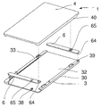
도 1 및 도 2는 신용 카드 또는 유사 물품(2)을 보관하도록 설계된 본 발명의 보호 케이스(1)를 나타낸다. Figures 1 and 2 show a
신용 카드(2)에는 앞면(20)과 뒷면(21)이 있는데, 앞면(20)은 문자가 양각으로 표시되어 두께가 높아진 양각부(22)의 형태로 되어 있으며 그 주위로 주변부(23)가 있다.The
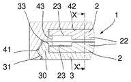
케이스(1)의 일측에는 개방부(10)가 있으며 그 반대 쪽에는 후측(11)이 있다. 케이스(1)는 대략 납작한 형상을 가지며 서로 미끄럼이동(슬라이드)하도록 설계된 두 부분, 즉, 제1부분(3)과 제2부분(4)으로 구성된다.On one side of the
제1부분(3)의 세 측면은 립(lip)(30)(도 3에도 도시되어 있음)을 포함하는데 이들 중 대향하는 두 립의 외측에는 레일(31)이 각각 형성되어 있으며, 제2부분(4)의 세 측면은 립(40)을 포함하되는데 이들 중 대향하는 두 립의 내측에는 홈(41)이 형성되어서 상기 레일(31)과 협동하여 슬라이드 작용하도록 되어 있다. The three sides of the
립(30)은 카드(2)가 수용되는 하우징(32)을 이루는데, 카드(2)는 립(30)이 없는 제4의 측면을 통해서 꺼낼 수 있다. 또한, 립(30)의 두 대향하는 부분의 내측에는 카드(2)의 주변부(23) 위로 연장되도록 형성된 돌출부(33)가 있다.The
더 정확하게 도 3을 참조하면, 립(30)의 높이는 카드(2)의 두께보다 약간 더 크고, 돌출부(33)의 깊이는 양각부(22)의 깊이보다 더 크고 그 폭은 주변부(23)의 폭보다 작은 것이 바람직함을 알 수 있다. 3, the height of the
실제 적용시에, 사용자가 제1부분(3)을 제2부분(4)으로 슬라이딩하면, 사용자는 카드(2)에 접근할 수 있게 되어서, 카드를 밀어서 제1부분(3)에서 빼낼 수 있게 된다. In practical application, when the user slides the
제1부분(3)의 치수적 특징에 의해서, 카드(2)와 특히 그 양각부(22)는 제2부분(4)과 접촉하지 않게 되어서 카드를 보호하는 데 도움이 된다.By virtue of the dimensional characteristics of the
카드(2)가 제1부분(3)의 하우징(32) 밖으로 예기치 않게 미끄러져 나오는 것을 방지하기 위하여 횡방향 고정 수단(lateral immobilisation means)을 구비하는게 유리하다. 횡방향 고정 수단의 예를 들면, 립(30)의 내측면에 상기 돌출부 아래에 하나 이상의 보스(boss)를 형성하여서 카드(2)를 역방향을 제외하고는 충분히 차단하도록 할 수 있다. 케이스의 제조 방법 및 그 재료에 따라서는, 상기 고정 수단은 금형 성형으로 제작할 수도 있고 부착형 부품으로서 제작할 수도 있다. It is advantageous to have lateral immobilization means to prevent the
이와 동일한 방식으로, 제1부분(3)과 제2부분(4)이 예기치 않게 슬라이드되는 것을 방지하기 위한 수단을 구비할 수 있다. In the same manner, means for preventing the
도 4a는 본 발명의 다른 실시예를 나타내는 것으로서, 두 부품만으로 구성되면서도 그 안에 두 장의 카드(2)를 보관할 수 있는 실시예를 나타낸다. FIG. 4A shows another embodiment of the present invention, which shows an embodiment in which two
이를 위해, 제1부분(3)은 도 1, 2, 3에 나타낸 것과 동일하지만, 제2부분(4)의 립(40)은 제2의 카드(2)가 수용될 수 있는 하우징(42)을 구성하되, 제1부분(3)의 하우징(32)에 대향하며 동일한 치수(즉, 그 깊이가 카드(2)의 두께보다 약간 더 크게)로 구성하고 있다. 그리고 양각부(22)의 깊이보다 큰 깊이로 카드 주변부 주위에 돌출부(43)가 형성된다. 1, 2 and 3, the
도면을 보면 두 장의 카드(2)가 서로 접촉할 수 없게 되어 있어서 카드(2)의 손상 위험이 없음을 알 수 있다. It can be seen from the drawing that there is no risk of damaging the
또한 도 5로부터 알 수 있는 바와 같이, 제2부분(4)에 담겨 있는 카드(2)를 추출할 수 있는 개방부는 제1부분(3)에 들어 있는 카드(2)를 추출할 수 있는 개방부가 있는 쪽과 반대 쪽에 있다. 따라서 두 부분(3, 4)을 서로에 대해서 밀면, 두 개의 카드에 동시에 접근할 수 있게 된다.As can be seen from Fig. 5, the opening portion capable of extracting the
이 도면에서는 카드를 카드의 길이 방향으로 미는 것을 보여주고 있지만, 다른 방향으로 카드를 밀 수 있도록 케이스를 설계하는 것도 가능함은 물론이다. Although the figure shows that the card is pushed in the longitudinal direction of the card, it is of course possible to design the case so that the card can be pushed in the other direction.
도 4b는 두 장의 카드를 보관할 수 있는 또 다른 형태의 보호 케이스를 나타낸다. 4B shows another type of protective case in which two cards can be stored.
이 형태에서, 케이스는, 세 부분, 즉, 중간 부분(5) 및 전술한 바와 같은 두 개의 제1부분(3)으로 구성된다. 중간 부분(5)은 등이 맞대도록 조립된 두 개의 제2부분(4)의 형태를 취한다. 즉, 중간 부분(5)은 그 3개 측 상의 각 표면상에 립(50)을 포함하는데, 두 대향하는 부분의 각 내측에는 홈(51)이 형성되어, 제1부분(3)의 레일(31)이 이 홈(51)과 함께 작용하도록 설계된다.In this form, the case is composed of three parts, namely an
이러한 다른 형태의 실시예에서, 제1부분(3)은 중간 부분(5)에 대해서 동일 방향으로 또는 반대 방향으로 슬라이딩할 수 있다. 심지어 제1부분(3)은 서로 다른 두 방향으로, 즉, 서로 수직 방향으로 슬라이딩할 수도 있음을 생각할 수 있다. In this alternative embodiment, the
슬라이딩을 보조하는 수단을 구비할 수 있다. 따라서 이 도 4b는 립(30) 내에서 하우징(34)에 둘러싸인 스프링(R)이 있는 것을 나타내는데, 이 스프링은 슬라이딩을 보조할 수 있으며, 이 보조 작용은 필요에 따라서는 개방시에 제공될 수도 있지만 닫을 때에 제공되는 것이 바람직하다.And means for assisting sliding. 4b thus shows that there is a spring R surrounded by the
또한, 도 4a 및 도 5에 도시된 두 부분만으로 구성된 유형의 경우에도, 스프링을 사용하여 슬라이딩을 보조하는 수단을 구비하는 것이 가능할 것이다. 이 경우에, 스프링(들)은 케이스를 닫을 때에는 복귀 스프링(들)으로서 작용하는 반면에, 두 부분(3, 4)은 각각, 하우징(42 및 32)에 담긴 카드와 협동하도록 설계된 멈춤 부재를 갖는다. 이로써, 슬라이딩 시에 이들 멈춤 부재는 카드 위를 슬라이딩하여서 카드 뒤로 위치하게 되고, 닫을 때에는 스프링(들)의 작용에 의해서 카드들을 추출시킨다.Also in the case of the type consisting of only the two parts shown in Figs. 4A and 5, it would be possible to provide means for assisting the sliding using the spring. In this case, the spring (s) act as return spring (s) when closing the case, while the two
도 4c는 4장의 카드(2)를 보관할 수 있는 다른 형태를 나타낸다. 이 실시예는 사실상 도 4a에 나타낸 경우의 중첩 형태로서, 중간 부분(5)이 또한 두 개의 하우징(52)을 포함한다.4C shows another form in which four
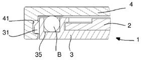
도 4d 및 4g는 한 장의 카드(2)만을 보관할 수 있는 케이스(1)를 나타내는 것으로서, 제1부분(3)에 레일(31)과 평행하게 오목부(recess)(35)가 형성되고 이 속에, 슬라이딩을 용이하게 하기 위하여 제2부분(4)에 대해서 구를 수 있는 볼(B)(도 4d의 경우) 또는 롤러(A)(도 4g의 경우)가 설치된다. 4D and 4G show a
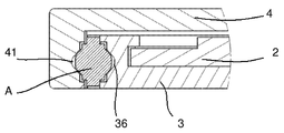
도 4e 및 4f는 한 장의 카드(2) 만을 보관할 수 있는 케이스(1)를 나타내는 것으로서, 제1부분(3)에는 레일 대신에 홈(36)이 형성되고 이 홈(36)을, 볼(B)(도 4e의 경우) 또는 롤러(A)(도 4f의 경우)를 이용하여 제2부분(4)의 홈(41)과 결합시킨다. 4E and 4F show a
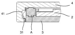
도 4h 및 도 4i는 제1부분(3)을 제2부분(4) 위에서 슬라이딩시키는 시스템에 관한 변형예를 나타낸다. 여기서 제1부분(3)은 제2부분(4)을 마주보는 쪽에 슬라이딩 방향과 평행하게 종방향 관통구(orifice)(37)가 형성되고, 이는 제2부분(4)에 형성된 페그(peg)(44)와 결합된다. Figures 4h and 4i show a variant on a system for sliding the
도 4h에 도시된 형태에서 페그(44)는, 제1부분(3)을 정위치에 놓은 후에, 관통구(37)를 통과하도록 눌러서 제2부분(4)에 연결시키고, 도 4i에 도시된 형태에서는 페그(44)를 제2부분(4)에 일체로 형성하고 강제끼움 방식으로 관통구(37)에 결합시킨다. The
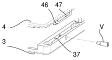
도 4j는 또다른 구성을 나타내는 것으로, 제2부분(4)의 주변부의 측면에, 제1부분(3)의 관통구 또는 홈(37) 내로 삽입되도록 돌출되며, 슬라이딩 시에 이 홈(37) 내에서 제한된 방식으로 이동할 수 있는 종방향 융기부(46)가 형성되어 있다. 각 융기부(46)는 홈(37)을 관통하여 핀이나 이와 유사한 물품(V)(스크류가 바람직함)이 결합되는 긴 타원형의 장공(47)을 포함한다.4J shows another configuration and is protruded to be inserted into the through hole or groove 37 of the
홈(37)의 끝 부분에는 움직임을 완충하고 작동 소음을 제한하기 위한 멈춤부(도시하지 않음)가 구비되는 것이 유리할 것이다.At the end of the
일반적으로, 두 부분(3, 4)은 동일하게 설계될 수도 있지만 비대칭형으로 설계할 수도 있을 것이다. 즉, 제1부분(3)과 제2부분(4)을 암컷 형태와 수컷 형태의 부분으로 구성하여서 한 부분을 타 부분 주위로 회전시킨 후에 서로 조립할 수 있을 것이다. In general, the two
도 6은 본 발명에 따른 케이스(1)의 특정 실시예를 나타낸다. Figure 6 shows a specific embodiment of the
이 실시예에서는 조립 형태가 도 4i에 나타낸 것과 유사한데, 제1부분(3)의 립(30)이 두 대향면에만 형성되어 있으며, 케이스(1)의 뒷면을 구성하는 제3면에는 제2부분(4)의 내측 표면에서 돌출되어 있는 스터드(stud)(45)(도면에 점선으로 표시하였음)에, 레버(6)의 일단부(61)에 있는 긴 타원 형태의 구멍(60)이 결합되어 레버(6)가 회전가능하게 장착된다. 레버(6)에는 이 구멍(60)에 가깝게 제2 구멍(62)이 있는데, 여기에는 제1부분(3)과 일체로 형성된 스터드(38)가 삽입된다.In this embodiment, the assembly type is similar to that shown in Fig. 4I. The
제1부분(3) 위에서의 제2부분(4)의 슬라이딩 운동에 의해서 레버(6)가 회전하고, 그 자유단(63)이 카드(도시하지 않았음)를 케이스(1) 밖으로 밀어낸다. 구멍(60)의 긴 타원형태에 의해서, 스터드(45)의 축과 편심된 스터드(38)의 움직임이 보상될 수 있다. 카드(2)의 이동 진폭은 레버(6)의 자유단(63)의 이동 진폭에 의존하는데, 이 자유단의 이동 진폭은 제1부분(3)에 대한 제2부분(4)의 이동 진폭 및 두 구멍(60, 62) 사이의 거리에 의존한다. The
일어나는 감배 효과(demultiplication)에 의해서, 제1부분(3)에 대한 제2부분(4)의 작은 이동 진폭으로도 카드(2)를 충분히 밖으로 밀어낼 수 있다. The
스프링(R)이 있으므로 해서, 카드(2)의 추출 후에 제1부분(3)과 제2부분(4)은 그 최초 위치로 복귀할 수 있다.Because of the presence of the spring R, the
이 실시예는, 제1부분(3)이 중간 부분이 되고 그 위에서 두 개의 제2부분(4)이 슬라이딩되도록 하는 대칭형을 취함으로써 2장의 카드(2)를 보관하는 변형 실시예로서 완벽하게 구성할 수 있을 것이다.This embodiment is completely constituted as an alternative embodiment in which two
또한, 이러한 다른 실시예의 경우, 두 개의 제2부분(4)은 수직 방향으로 슬라이딩될 수도 있을 것이다. Also, in this alternative embodiment, the two
도 7은, 두 부분(3, 4)으로만 이루어지면서 카드(2)를 추출하는 시스템을 갖는, 두 장의 카드(2)를 보관할 수 있는 다른 형태의 실시예를 나타낸다. Fig. 7 shows another embodiment in which two
두 부분(3, 4)은 상하로 슬라이딩 되도록 설치되며, 복귀 스프링(도시하지 않음)이 구비된다. 각 부분(3, 4)은 하우징(32, 42)과 레버(6)를 포함한다. 제2부분(4)의 하우징(42)은 도면에서 보이지 않는다. 그리고 레버(6)에는 그 일단에 회전축(64)이 있고 이에 가까운 위치에 구멍(65)이 형성되어 있다. The two
제1부분(3)의 하우징(32)에 담긴 카드를 추출하기 위한 레버(6)는, 제1부분(3)에서 돌출된 스터드(38)에 그 구멍(65)을 통해 장착된다. 이 레버의 회전축(64)은 제2부분(4)의 립(40)의 구멍(도면에서는 보이지 않음)에 삽입된다.The
마찬가지로, 제2부분(3)의 하우징(42)에 담긴 카드를 추출하기 위한 레버(6)는, 제2부분(4)에서 돌출된 스터드(도면에서는 보이지 않음)에 그 구멍(65)을 통해 장착된다. 이 레버의 회전축(64)은 제1부분(3)의 립(30)의 구멍(39)에 삽입된다.Likewise, the
이들 레버(6)의 두께는 당연히 카드의 두께에 의해 제한되며, 하우징(32 또는 42) 내에서 카드(2)가 점유하는 공간 내에서만 이동된다.The thickness of these
제1부분(3)과 제2부분(4)의 상대적인 슬라이딩 시에, 제2부분(4)은, 레버(6)의 구멍(65)에 결합된 스터드(도면에 보이지 않음)에 의해서(이 레버는 회전축(64)에 의해서 제1부분(3)의 구멍(39)에 결합되어 있음) 회전하게 되며, 이에 하우징(42)에 담긴 카드(보이지 않음)가 추출된다. The
이와 동시에, 제1부분(3)은, 제2 레버(6)의 구멍(65)에 결합된 스터드(38)에 의해서(이 레버는 회전축(64)에 의해서 제2부분(4)의 구멍(보이지 않음)에 결합되어 있음) 회전하게 되며, 이에 하우징(32)에 담긴 카드가 추출된다.At the same time the
도 6에 도시된 실시예에서, 구멍(65)으로부터 회전축(64)까지의 거리가 카드의 추출의 감배 효과(demultiplication)의 정도를 결정한다. In the embodiment shown in FIG. 6, the distance from
도 8은 카드를 4장까지 보관할 수 있는 다른 형태의 케이스를 나타낸다. 제1부분(3) 및 제2부분(4)의 각각이 2중의 하우징으로 구성되어서 2장의 카드들이 돌출부 33과 43(도면에는 보이지 않음)을 통해서 서로 독립적으로 그리고 서로 평행하게 미끄럼 이동될 수 있다. 그리고 레버(6)에는 2중 하우징의 두께에 대응하는 두께를 갖는 근단부(proximal part)(66)와 이 두께의 절반의 두께를 갖는 원단부(distal part)(67)가 있으며, 이들 두 부분, 즉, 근단부(66)와 원단부(67)의 접합부는 숄더(68)를 이루고 있다.Fig. 8 shows another type of case in which up to four cards can be stored. Each of the
두 부분(3과 4)이 서로에 대해서 슬라이딩시에 각 레버(6)가 두 카드를 밀어내는데, 하나는 원단부(67)가, 다른 하나는 숄더(68)가 밀어내어서 카드들이 어긋나게 추출됨을 이해할 것이다.When the two
전체적으로, 어느 실시예를 고려하든, 제2부분(4)에 대한 제1부분(3)의 상이한 위치들을 식별표시(index)하기 위하여, 두 부분(3, 4) 상에, 원하는 동작을 용이하게 하는 위치에 그리고 그 방향으로 예컨대 자석을 설치하는 것이 가능하다. Overall, whichever embodiment is taken into account, on the two
따라서, 이들 위치를 표시하기 위하여 두 부분(3, 4)의 서로 상대적인 끝단 위치에서는 자석이 서로 끌어당기도록 하고, 중간 위치에서는 서로를 밀어내어 슬라이딩을 용이하게 하도록 구성하는 것이 가능하다.Therefore, in order to display these positions, it is possible to configure the magnets to be attracted to each other at the end positions relative to each other of the two
또한, 전반적으로, 개방시에 제1부분(3)과 제2부분(4)이 서로 슬라이드될 때에, 후퇴되어서 케이스를 막을 수 있는 플랩(flap)을 회전가능하게 그리고/또는 슬라이드가능하게 설치할 수 있다.In general, when the
이상 설명한 모든 실시예에서, 케이스(1)는 한 장 이상의 신용 카드 또는 유사 물품을 손상의 위험없이 보관할 수 있다. In all of the embodiments described above, the
본 발명에 따른 보호 케이스는 그 안에 담긴 카드(들)를 물리적으로 보호할 뿐만 아니라, 실시예에 따라서는 카드(들)에 표기된 정보를 원격으로 읽히는 것을 방지할 수 있다.The protective case according to the present invention not only physically protects the card (s) contained therein, but also, in some embodiments, can prevent the information displayed on the card (s) from being read remotely.
실제로, 비접촉식 신용 카드의 사용이 빠르게 증가하고 있으며 이에 따라 카드 소지자의 은행 정보들을 원격으로 읽는 등의 부정행위의 위험이 증가하고 있다.In fact, the use of contactless credit cards is growing rapidly, which increases the risk of fraudulent activities such as reading cardholder banking information remotely.
유리한 점은, 본 발명의 케이스는 부분적으로 또는 전체적으로, 전자파의 통과를 막을 수 있는 전자기적 장벽으로 구성할 수 있다는 것이다. Advantageously, the case of the present invention can be made, in part or in whole, of an electromagnetic barrier capable of blocking the passage of electromagnetic waves.
따라서 외벽을 금속으로 만들거나 금속으로 코팅할 수 있고, 바람직하게는 접촉 수단이 이들 금속 부분에 연결되어서 격실(cage)을 형성하도록 할 수 있다.The outer walls can thus be made of metal or coated with metal, and preferably the contact means can be connected to these metal parts to form a cage.
상기 접촉 수단은 케이스가 열릴 때에는 비활성화되고 케이스가 닫힐 때에 활성화되도록 설계할 수 있어서, 케이스에서 카드를 꺼내지 않고 단순히 케이스를 열기만 함으로써 카드의 비접촉 기능을 이용할 수 있는 이점을 알게 될 것이다.The contact means can be designed to be deactivated when the case is opened and activated when the case is closed so that the advantage of utilizing the contactless function of the card by simply opening the case without removing the card from the case will be noticed.
Claims (16)
상기 케이스는, 보호하고자 할 카드(2)가 수용되는 공간을 이루는 두 개의 평행한 벽들로 구성되며 그 일측에는 카드(2)의 삽입 또는 추출이 가능한 개방부(10)가 구비되는 납작한 외피 형상을 갖고,
상기 두 개의 평행한 벽들 중 하나를 각각 포함하는 적어도 2개의 부분(3, 4, 5)을 포함하고, 상기 적어도 2개의 부분(3, 4, 5) 중 한 부분은 타 부분에 슬라이딩 가능하도록 설치되고, 상기 카드(2)를 수용 및 유지할 수 있는 형상으로 형성되며, 이를 위해, 카드(2)가 슬라이딩해서 들어갈 수 있는 하우징(32, 42, 52)을 포함하되,
상기 하우징(32, 42, 52)은 한편으로는 카드(2)를 안착시키기 위하여 가역적 카드 유지 수단을 그 일측에 포함하고 다른 한편으로는 상기 카드(2)가 들어 있는 부분(3, 4, 5)을 슬라이딩 시킨 후에 카드(2)를 밀어서 추출할 수 있는 개방부를 갖는 것을 특징으로 하는 신용 카드 또는 유사 물품 보호용 케이스. In a case for protecting a credit card or similar article,
The case is formed of two parallel walls constituting a space for accommodating a card 2 to be protected and has a flat outer shape having an opening 10 through which the card 2 can be inserted or extracted Have,
And at least two portions (3, 4, 5) each including one of said two parallel walls, wherein one of said at least two portions (3, 4, 5) And a housing (32, 42, 52) which is formed in a shape capable of receiving and holding the card (2), and to which the card (2)
On the one hand, the housing (32, 42, 52) is provided with reversible cardholding means on one side for seating the card (2) and on the other hand a portion (3, 4, 5 (2) is slid, and then the card (2) is pushed out to be extracted.
타 부분에 슬라이딩 가능하도록 설치되는 부분은 그 안에 담긴 카드가 타 부분에 접촉할 수 없는 형태로 형성되고, 이를 위해, 상기 카드가 담기도록 설계된 하우징은 한편으로는 상기 카드(2)가 특정의 허용공차로 수용될 수 있도록 하는 폭방향 치수를 갖고, 다른 한편으로는 상기 개방부(10)가 있는 단부의 측변과 수직한 두 측변에 형성되며 상기 카드(2)를 유지하고 카드를 밀 수 있도록 카드의 주변부(23)를 덮을 수 있으며 상기 카드(2) 상에 양각된 양각부(22)의 두께보다 실질적으로 더 큰 두께를 갖는 돌출부(33, 43, 53)를 포함하는 것을 특징으로 하는 신용 카드 또는 유사 물품 보호용 케이스.The method according to claim 1,
A portion of the card that is slidably installed in the other portion is formed in a form such that the card contained therein can not contact the other portion. For this purpose, the housing designed to accommodate the card has, on the one hand, On the other hand, formed on both sides perpendicular to the sides of the end of the opening (10), and which holds the card (2) (33, 43, 53) capable of covering the peripheral portion (23) of the card (2) and having a thickness substantially greater than the thickness of the embossed portion (22) embossed on the card (2) Or similar article protection case.
적어도 2개의 부분(3, 4, 5) 각각은, 카드(2)가 타 부분(3, 4, 5) 또는 다른 카드(2)에 접촉할 수 없도록 카드를 수용 및 유지하는 형상으로 형성되고,
이를 위해, 상기 적어도 2개의 부분(3, 4, 5) 각각은, 타 부분(3, 4, 5)에 대향하는 측에, 한편으로는 상기 카드(2)가 특정의 허용공차로 수용될 수 있도록 하는 폭방향 치수를 갖고, 다른 한편으로는 상기 개방부가 있는 단부의 측변과 수직한 두 측변에 형성되며 상기 카드(2)를 유지하고 카드를 밀 수 있도록 카드의 주변부(23)를 덮을 수 있으며 상기 카드(2) 상에 양각된 양각부(22)의 두께보다 실질적으로 더 큰 두께를 갖는 돌출부(33, 43, 53)를 포함하는 하우징(32, 42, 52)과,
상기 하우징 내에 상기 카드(2)가 안착될 수 있도록 상기 카드(2)를 유지하는 가역적 카드 유지 수단을 포함하는 것을 특징으로 하는 신용 카드 또는 유사 물품 보호용 케이스. 3. The method of claim 2,
Each of the at least two portions 3, 4 and 5 is formed in a shape for receiving and holding the card so that the card 2 can not contact the other portions 3, 4, 5 or the other card 2,
To this end, each of the at least two portions (3, 4, 5) is provided on the opposite side to the other portions (3, 4, 5), on the one hand, , On the other hand, formed on both sides perpendicular to the sides of the end with said openings and can cover the periphery 23 of the card to hold the card 2 and to push the card A housing (32, 42, 52) including projections (33, 43, 53) having a thickness substantially greater than the thickness of the embossed portion (22) embossed on the card (2)
And a reversible card retention means for retaining the card (2) so that the card (2) can be seated in the housing.
3개의 부분(3, 5)을 포함하되, 한 장의 카드(2)를 지지하는 형상으로 형성되는 다른 두 부분(3)의 각각이 중간 부분(5) 위에서 슬라이딩될 수 있는 것을 특징으로 하는 신용 카드 또는 유사 물품 보호용 케이스.The method of claim 3,
Characterized in that each of the other two parts (3), including three parts (3, 5), formed in a shape to support a card (2), can slide on the intermediate part (5) Or similar article protection case.
중간 부분(5)은 그 각 측면에 카드(2)를 유지할 수 있는 하우징(52)을 포함하는 것을 특징으로 하는 신용 카드 또는 유사 물품 보호용 케이스. 5. The method of claim 4,
Characterized in that the intermediate part (5) comprises a housing (52) capable of holding the card (2) on each side thereof.
한 부분(3, 4, 5)의 타 부분에 대한 슬라이딩은, 이들 부분 중 한 부분은 두 개의 레일(31)을 포함하고 이들 레일의 각각은 타 부분에 있는 두 개의 홈(41, 51) 중 하나에 결합되는 슬라이딩 연결 구조에 의해서 이루어지는 것을 특징으로 하는 신용 카드 또는 유사 물품 보호용 케이스. 6. The method according to any one of claims 1 to 5,
Sliding relative to the other part of the part 3, 4, 5 is such that one part of these parts comprises two rails 31 and each of the two rails 31, Wherein the sliding connection structure is coupled to one of the first and second sliding doors.
한 부분(3, 4)의 타 부분에 대한 슬라이딩은, 상기 부분들 중 하나가 두 개의 홈(41)을 포함하되, 이 홈 각각은 타 부분에 있는 두 개의 홈(36) 중 하나와 대향하도록 배치되고, 볼(B) 또는 롤러(A)와 같은 중간 연결 부품이 상기 두 부분(3, 4) 사이에 상기 대향하는 두 홈(36, 41) 내에 배치되는 슬라이딩 연결 구조에 의해서 이루어지는 것을 특징으로 하는 신용 카드 또는 유사 물품 보호용 케이스.6. The method according to any one of claims 1 to 5,
Sliding relative to the other part of the part 3, 4 is such that one of the parts comprises two grooves 41, each of which faces one of the two grooves 36 in the other part , And an intermediate connecting part such as a ball (B) or a roller (A) is arranged between the two parts (3, 4) by means of a sliding connection structure in which two opposing grooves (36, 41) Cases for protecting credit cards or similar items.
상기 두 부분 중 하나는 그 측면에, 타 부분에 있는 홈 내로 삽입되어 종방향으로 슬라이딩될 수 있도록 형성된 융기부를 포함하며, 상기 홈은 이를 관통하는 핀이나 이와 유사한 물품을 이용하여 상기 융기부에 형성된 종방향으로 긴 타원형 장공과 결합되는 것을 특징으로 하는 신용 카드 또는 유사 물품 보호용 케이스.6. The method according to any one of claims 1 to 5,
Wherein one of the two portions includes a raised portion formed on its side so as to be inserted into the groove in the other portion and to be slidable in the longitudinal direction, the groove being formed in the raised portion by using a pin or the like penetrating therethrough And a long oval slot in the longitudinal direction.
하나의 부분(3, 4, 5)의 타 부분에 대한 상이한 위치들을 식별표시하는 수단을 포함하는 것을 특징으로 하는 신용 카드 또는 유사 물품 보호용 케이스.9. The method according to any one of claims 1 to 8,
Characterized in that it comprises means for identifying and indicating different positions for the other part of the one part (3, 4, 5).
상기 식별표시 수단은 자기적 장치로 구성되는 것을 특징으로 하는 신용 카드 또는 유사 물품 보호용 케이스.10. The method of claim 9,
Wherein the identification display means is constituted by a magnetic device.
하나의 부분(3, 4, 5)의 타 부분에 대한 슬라이딩을 보조하는 수단(R)을 포함하는 것을 특징으로 하는 신용 카드 또는 유사 물품 보호용 케이스.11. The method according to any one of claims 1 to 10,
And means (R) for assisting sliding of the other part of the one part (3, 4, 5).
상기 보조 수단은, 닫힘 방향으로 차단 작용을 하는 가역적 차단 수단과 함께 조합되어서, 개방 방향으로의 슬라이딩을 용이하게 하거나 또는 닫힘 방향으로의 슬라이딩을 용이하게 할 수 있도록 배치된 스프링(R)을 포함하는 것을 특징으로 하는 신용 카드 또는 유사 물품 보호용 케이스. 12. The method of claim 11,
The auxiliary means comprises a spring (R) arranged in combination with a reversible blocking means acting as a blocking action in the closing direction to facilitate sliding in the opening direction or to facilitate sliding in the closing direction And a case for protecting a credit card or similar article.
카드(2)를 배출하는 가동 수단(6)을 포함하되, 상기 수단(6)의 움직임은 하나의 부분(3, 4, 5)의 타 부분에 대한 슬라이딩과 연동되는 것을 특징으로 하는 신용 카드 또는 유사 물품 보호용 케이스.13. The method according to any one of claims 1 to 12,
Characterized in that the movement of the means (6) is interlocked with the sliding of one portion (3, 4, 5) of the other portion of the card (2) Cases for protection of similar items.
카드(2)의 하우징(32, 42, 52)은 카드가 추출되는 전용 측의 반대 측에 상기 카드(2)가 접하는 레버(6)를 포함하되, 이 레버(6)는 상기 하우징(32, 42, 52)을 포함하는 부분(3, 4, 5)에 회전가능하게 설치되며, 슬라이딩시에 타 부분에 의해서 회전 구동되는 것을 특징으로 하는 신용 카드 또는 유사 물품 보호용 케이스. 14. The method of claim 13,
The housing (32, 42, 52) of the card (2) includes a lever (6) to which the card (2) abuts on the opposite side of the dedicated side from which the card is extracted, 42, 52), and is rotatably driven by the other portion when sliding. The case for protecting a credit card or a similar article as set forth in claim 1,
보호하고자 할 카드(2)가 수용되는 공간을 이루는 두 개의 평행한 벽(3, 4)에는 각각, 전자파의 통과를 막을 수 있는 장벽을 구성하는 재료가 덧대이고 및/또는 상기 벽은 상기 재료로 제작되는 것을 특징으로 하는 신용 카드 또는 유사 물품 보호용 케이스.15. The method according to any one of claims 1 to 14,
The two parallel walls 3 and 4 constituting the space in which the card 2 to be protected is accommodated are padded with a material constituting a barrier capable of blocking the passage of electromagnetic waves and / And a case for protecting a credit card or similar article.
접촉 수단을 포함하되, 상기 접촉 수단은 비활성화시에 두 장벽을 연결하는 것을 특징으로 하는 신용 카드 또는 유사 물품 보호용 케이스. 16. The method of claim 15,
And a contact means, said contact means connecting the two barriers upon deactivation.
Applications Claiming Priority (3)
| Application Number | Priority Date | Filing Date | Title |
|---|---|---|---|
| FR1251702A FR2987241B1 (en) | 2012-02-24 | 2012-02-24 | CASE FOR PROTECTING A CREDIT CARD OR THE LIKE. |
| FR1251702 | 2012-02-24 | ||
| PCT/FR2013/050364 WO2013124593A1 (en) | 2012-02-24 | 2013-02-22 | Protective case for a credit card or similar |
Publications (2)
| Publication Number | Publication Date |
|---|---|
| KR20140129281A true KR20140129281A (en) | 2014-11-06 |
| KR102023680B1 KR102023680B1 (en) | 2019-09-23 |
Family
ID=47901218
Family Applications (1)
| Application Number | Title | Priority Date | Filing Date |
|---|---|---|---|
| KR1020147026812A KR102023680B1 (en) | 2012-02-24 | 2013-02-22 | Protective case for a credit card or similar |
Country Status (20)
| Country | Link |
|---|---|
| US (1) | US10016037B2 (en) |
| EP (1) | EP2816927B1 (en) |
| JP (1) | JP6199906B2 (en) |
| KR (1) | KR102023680B1 (en) |
| CN (1) | CN104302204B (en) |
| AU (1) | AU2013223921B2 (en) |
| BR (1) | BR112014021630B1 (en) |
| CA (1) | CA2864140C (en) |
| EA (1) | EA028981B1 (en) |
| ES (1) | ES2748047T3 (en) |
| FR (1) | FR2987241B1 (en) |
| HK (1) | HK1205889A1 (en) |
| IN (1) | IN2014DN07916A (en) |
| MX (1) | MX357134B (en) |
| MY (1) | MY171114A (en) |
| PL (1) | PL2816927T3 (en) |
| SG (1) | SG11201405062WA (en) |
| UA (1) | UA115324C2 (en) |
| WO (1) | WO2013124593A1 (en) |
| ZA (1) | ZA201406730B (en) |
Families Citing this family (6)
| Publication number | Priority date | Publication date | Assignee | Title |
|---|---|---|---|---|
| US9339094B2 (en) | 2014-07-28 | 2016-05-17 | Spectre Wallets | Credit card holder and wallet |
| US9876523B2 (en) | 2015-04-24 | 2018-01-23 | Ahmad H. HODROJ | Smartphone case with concealed card cache, and method of using same |
| US11369186B1 (en) * | 2019-07-16 | 2022-06-28 | Full Coverage Security Solutions, LLC | Credit card/identity card holder |
| USD993324S1 (en) * | 2020-02-28 | 2023-07-25 | Certified Guaranty Company, LLC | Case for a trading card |
| USD971338S1 (en) * | 2020-02-28 | 2022-11-29 | Certified Guaranty Company, LLC | Case for a trading card |
| US11344091B2 (en) | 2020-09-15 | 2022-05-31 | Peter M. Goodwin | Mechanical wallet |
Citations (5)
| Publication number | Priority date | Publication date | Assignee | Title |
|---|---|---|---|---|
| JPS5133115U (en) * | 1974-08-31 | 1976-03-11 | ||
| JPS6321285Y2 (en) * | 1981-08-03 | 1988-06-13 | ||
| US20050224149A1 (en) * | 2004-04-08 | 2005-10-13 | Tiscione James A | High-capacity card holder and ejector |
| KR20080000403U (en) * | 2006-10-02 | 2008-04-08 | 임정남 | credit card holder structure |
| KR20080067696A (en) * | 2005-11-15 | 2008-07-21 | 에리쉬 끄랑 에 아소씨에 | Protective case for credit card or the like |
Family Cites Families (25)
| Publication number | Priority date | Publication date | Assignee | Title |
|---|---|---|---|---|
| US2640347A (en) * | 1951-04-30 | 1953-06-02 | Joseph J Majeski | Key case |
| US3688896A (en) * | 1970-04-15 | 1972-09-05 | Strohm Newell | Card case |
| US4202445A (en) * | 1978-10-31 | 1980-05-13 | Porter Charles B A | Security wallet or container |
| ATE34286T1 (en) * | 1984-03-28 | 1988-06-15 | Franz Josef Holdener | CASE FOR CREDIT AND IDENTIFICATION CARDS. |
| IT213189Z2 (en) * | 1987-04-14 | 1989-11-09 | Fab Trading Srl | CONTAINER FOR CARDBOARDS SUCH AS, IN PARTICULAR, SIMILAR CREDIT CARDS |
| US5080222A (en) * | 1991-06-06 | 1992-01-14 | Tenax Corporation | Child resistant medicine box |
| DE9406180U1 (en) | 1994-04-14 | 1994-06-30 | Schueler Wolfgang | Credit card sleeve |
| ATE190206T1 (en) | 1994-12-16 | 2000-03-15 | Schoettli Theodore | PLASTIC CARRIER FOR TWO CREDIT CARDS |
| SE9601825L (en) * | 1996-05-13 | 1997-05-20 | Ohlson Kurt L | Korthållararrangemang |
| US6412627B1 (en) * | 2000-01-05 | 2002-07-02 | James Allen Tiscione | Card holder and ejector |
| JP2002142841A (en) * | 2000-11-15 | 2002-05-21 | Ykk Corp | Small article container |
| US6581762B2 (en) * | 2001-09-24 | 2003-06-24 | Robert Keough | Personal object holding device |
| USD465729S1 (en) * | 2001-11-27 | 2002-11-19 | Kenshi Nishimura | Slide open container |
| USD479462S1 (en) * | 2002-08-09 | 2003-09-09 | Kado Industrial Company Limited | Container for tie tamer |
| US7004312B2 (en) * | 2003-10-22 | 2006-02-28 | Hsin Wang Chen | Aluminum business card box |
| FR2876553B1 (en) * | 2004-10-20 | 2007-01-26 | Louis Michel Jean | CREDIT CARD HOLDER DEVICE FOR SIMPLIFYING THE PORT AND PROVIDING A CREDIT CARD FOR USE |
| USD557053S1 (en) * | 2004-12-15 | 2007-12-11 | Osborn Warren R | Case for CD or DVD |
| US20070109130A1 (en) * | 2005-11-17 | 2007-05-17 | Edenfield Benjamin W | Card cases and wallets with radio frequency shielding |
| US8443854B2 (en) * | 2007-10-18 | 2013-05-21 | Novate Media Llc | Sliding drawer card holder and extractor |
| NL1036993C2 (en) * | 2009-05-27 | 2010-11-30 | Geer Rene Johan Van | HOLDER FOR CREDIT CARDS. |
| FR2946507B1 (en) * | 2009-06-12 | 2011-08-05 | H M K | PROTECTIVE CASE FOR CREDIT CARD OR SIMILAR READING WITHOUT CONTACT. |
| CN202750891U (en) * | 2012-02-24 | 2013-02-27 | 勃来迪环球股份有限公司 | Card holder with prop up piece |
| US10793342B2 (en) * | 2012-07-16 | 2020-10-06 | John Minson | Credit card dispenser |
| US9125465B2 (en) * | 2012-08-29 | 2015-09-08 | Daniel Vern Beckley | Wallet |
| US9339094B2 (en) * | 2014-07-28 | 2016-05-17 | Spectre Wallets | Credit card holder and wallet |
-
2012
- 2012-02-24 FR FR1251702A patent/FR2987241B1/en not_active Expired - Fee Related
-
2013
- 2013-02-22 CN CN201380010536.5A patent/CN104302204B/en active Active
- 2013-02-22 KR KR1020147026812A patent/KR102023680B1/en active IP Right Grant
- 2013-02-22 WO PCT/FR2013/050364 patent/WO2013124593A1/en active Application Filing
- 2013-02-22 AU AU2013223921A patent/AU2013223921B2/en active Active
- 2013-02-22 CA CA2864140A patent/CA2864140C/en active Active
- 2013-02-22 MX MX2014010129A patent/MX357134B/en active IP Right Grant
- 2013-02-22 MY MYPI2014702335A patent/MY171114A/en unknown
- 2013-02-22 SG SG11201405062WA patent/SG11201405062WA/en unknown
- 2013-02-22 PL PL13710505T patent/PL2816927T3/en unknown
- 2013-02-22 BR BR112014021630-4A patent/BR112014021630B1/en active IP Right Grant
- 2013-02-22 UA UAA201409943A patent/UA115324C2/en unknown
- 2013-02-22 EP EP13710505.2A patent/EP2816927B1/en active Active
- 2013-02-22 JP JP2014558187A patent/JP6199906B2/en active Active
- 2013-02-22 US US14/379,740 patent/US10016037B2/en active Active
- 2013-02-22 EA EA201400952A patent/EA028981B1/en not_active IP Right Cessation
- 2013-02-22 ES ES13710505T patent/ES2748047T3/en active Active
-
2014
- 2014-09-12 ZA ZA2014/06730A patent/ZA201406730B/en unknown
- 2014-09-22 IN IN7916DEN2014 patent/IN2014DN07916A/en unknown
-
2015
- 2015-07-09 HK HK15106549.6A patent/HK1205889A1/en unknown
Patent Citations (5)
| Publication number | Priority date | Publication date | Assignee | Title |
|---|---|---|---|---|
| JPS5133115U (en) * | 1974-08-31 | 1976-03-11 | ||
| JPS6321285Y2 (en) * | 1981-08-03 | 1988-06-13 | ||
| US20050224149A1 (en) * | 2004-04-08 | 2005-10-13 | Tiscione James A | High-capacity card holder and ejector |
| KR20080067696A (en) * | 2005-11-15 | 2008-07-21 | 에리쉬 끄랑 에 아소씨에 | Protective case for credit card or the like |
| KR20080000403U (en) * | 2006-10-02 | 2008-04-08 | 임정남 | credit card holder structure |
Also Published As
| Publication number | Publication date |
|---|---|
| BR112014021630B1 (en) | 2021-07-20 |
| FR2987241A1 (en) | 2013-08-30 |
| JP6199906B2 (en) | 2017-09-20 |
| CN104302204B (en) | 2016-09-14 |
| IN2014DN07916A (en) | 2015-05-01 |
| FR2987241B1 (en) | 2016-06-24 |
| AU2013223921B2 (en) | 2015-12-17 |
| KR102023680B1 (en) | 2019-09-23 |
| US10016037B2 (en) | 2018-07-10 |
| AU2013223921A1 (en) | 2014-10-02 |
| EP2816927B1 (en) | 2019-07-03 |
| ZA201406730B (en) | 2015-11-25 |
| EA028981B1 (en) | 2018-01-31 |
| US20150041032A1 (en) | 2015-02-12 |
| UA115324C2 (en) | 2017-10-25 |
| WO2013124593A1 (en) | 2013-08-29 |
| EP2816927A1 (en) | 2014-12-31 |
| PL2816927T3 (en) | 2020-01-31 |
| CA2864140A1 (en) | 2013-08-29 |
| MX357134B (en) | 2018-06-08 |
| ES2748047T3 (en) | 2020-03-12 |
| SG11201405062WA (en) | 2014-10-30 |
| CN104302204A (en) | 2015-01-21 |
| JP2015507996A (en) | 2015-03-16 |
| MX2014010129A (en) | 2014-11-26 |
| CA2864140C (en) | 2017-03-28 |
| MY171114A (en) | 2019-09-26 |
| EA201400952A1 (en) | 2015-01-30 |
| HK1205889A1 (en) | 2015-12-31 |
Similar Documents
| Publication | Publication Date | Title |
|---|---|---|
| KR20140130201A (en) | Protective case for at least two credit cards or the like | |
| KR20140129281A (en) | Protective case for a credit card or similar | |
| JP6326689B2 (en) | Credit card holder with improved ejector / ejector | |
| CA1286257C (en) | Devices for holding credit cards and check cards | |
| US5740624A (en) | Identification card holder | |
| NL1036993C2 (en) | HOLDER FOR CREDIT CARDS. | |
| CN108790474A (en) | For credit card or the card holder of other cards | |
| US20100012239A1 (en) | Protective Case for Credit Card or the Like | |
| US7055690B1 (en) | Partitioned card box for collectible cards and treated with friction reducing means | |
| KR101442157B1 (en) | Case for Mobile Phone | |
| WO2012069789A1 (en) | Smart card holder | |
| WO1991001096A1 (en) | Container for cards or the like flat objects | |
| US20140345759A1 (en) | Personal card removal apparatus | |
| US9460378B2 (en) | Ultra slim card incorporating a USB device | |
| USD559253S1 (en) | Combination magnetic stripe and contactless reader | |
| US20240135128A1 (en) | Transaction card with storage for a physical key | |
| CN220255901U (en) | Composite card bag | |
| RU199387U1 (en) | CASE FOR CARDS | |
| JP4028494B2 (en) | card case | |
| KR101506692B1 (en) | Means for storing coins which has card shape |
Legal Events
| Date | Code | Title | Description |
|---|---|---|---|
| A201 | Request for examination | ||
| E902 | Notification of reason for refusal | ||
| E701 | Decision to grant or registration of patent right | ||
| GRNT | Written decision to grant |