KR20140129047A - Beam scanning system - Google Patents
Beam scanning system Download PDFInfo
- Publication number
- KR20140129047A KR20140129047A KR1020147023443A KR20147023443A KR20140129047A KR 20140129047 A KR20140129047 A KR 20140129047A KR 1020147023443 A KR1020147023443 A KR 1020147023443A KR 20147023443 A KR20147023443 A KR 20147023443A KR 20140129047 A KR20140129047 A KR 20140129047A
- Authority
- KR
- South Korea
- Prior art keywords
- probe
- lens
- angle
- detection
- sample
- Prior art date
Links
Images


Classifications
-
- G—PHYSICS
- G01—MEASURING; TESTING
- G01Q—SCANNING-PROBE TECHNIQUES OR APPARATUS; APPLICATIONS OF SCANNING-PROBE TECHNIQUES, e.g. SCANNING PROBE MICROSCOPY [SPM]
- G01Q20/00—Monitoring the movement or position of the probe
- G01Q20/02—Monitoring the movement or position of the probe by optical means
-
- G—PHYSICS
- G01—MEASURING; TESTING
- G01Q—SCANNING-PROBE TECHNIQUES OR APPARATUS; APPLICATIONS OF SCANNING-PROBE TECHNIQUES, e.g. SCANNING PROBE MICROSCOPY [SPM]
- G01Q10/00—Scanning or positioning arrangements, i.e. arrangements for actively controlling the movement or position of the probe
-
- G—PHYSICS
- G01—MEASURING; TESTING
- G01Q—SCANNING-PROBE TECHNIQUES OR APPARATUS; APPLICATIONS OF SCANNING-PROBE TECHNIQUES, e.g. SCANNING PROBE MICROSCOPY [SPM]
- G01Q10/00—Scanning or positioning arrangements, i.e. arrangements for actively controlling the movement or position of the probe
- G01Q10/04—Fine scanning or positioning
- G01Q10/045—Self-actuating probes, i.e. wherein the actuating means for driving are part of the probe itself, e.g. piezoelectric means on a cantilever probe
Abstract
본 발명은 탐침 현미경의 탐침을 조명하기 위한 장치에 관한 것이다. 렌즈는 빔을 수신하여 그것을 탐침에 집속(focus)하게 배치된다. 스캐닝 시스템은 빔이 그 광축에 대한 각도로 렌즈에 입사하는 입사각이 시간이 지남에 따라 변하게 한다. 스캐닝 시스템은 전형적으로 탐침의 이동을 추적하도록 빔을 이동시키게 배치되어서, 빔이 집속되는 곳에 탐침 상의 구역을 유지한다. 스캐닝 시스템은 렌즈를 향하는 방향으로 빔을 반사하는 빔 스티어링 거울과; 빔 스티어링 거울을 회전시키기 위한 거울 작동기를 포함한다.The present invention relates to an apparatus for illuminating a probe of a probe microscope. The lens is arranged to receive the beam and focus it on the probe. The scanning system causes the incident angle at which the beam is incident on the lens at an angle to its optical axis to change over time. The scanning system is typically arranged to move the beam so as to track the movement of the probe, thereby maintaining the area on the probe where the beam is focused. The scanning system includes: a beam-steering mirror for reflecting a beam in a direction toward the lens; And a mirror actuator for rotating the beam-steering mirror.
Description
본 발명은 탐침 현미경을 조명하는 빔을 스캐닝하는 방법, 및 그 방법에 사용하기 위한 장치에 관한 것이다.The present invention relates to a method of scanning a beam illuminating a probe microscope, and an apparatus for use in the method.
US2009032706(A1)는 검출 빔이 스캐닝 렌즈를 통해 전달된 후, 외팔보 밖으로 반사 또는 산란되어 검출기에 의해 수신되는 고속 스캐닝 탐침 현미경을 기재했다. 렌즈는 그 움직임이 팁의 움직임과 동조하도록 스캐너에 의해 위치이동된다. 이러한 방식에서는 렌즈에 의해 생성된 집속된 스폿(focused spot)이 이동 외팔보를 추적한다. 렌즈의 사용은 다른 파장의 광을 가진 탐침을 조명할 때 렌즈의 색수차(chromatic aberration)에 의한 문제를 발생할 수 있다. 또한, 렌즈는 중량으로, 빠르게 이동하기 곤란하게 만들며, 현미경의 작동 속도를 제한할 수도 있다.US2009032706 (A1) describes a high-speed scanning probe microscope in which a detection beam is transmitted through a scanning lens and then reflected or scattered out of a cantilever and received by a detector. The lens is moved by the scanner so that its movement is synchronized with the motion of the tip. In this manner, a focused spot generated by the lens tracks the moving cantilever beam. The use of a lens can cause problems due to chromatic aberration of the lens when illuminating a probe with light of a different wavelength. In addition, the lens, by weight, makes it difficult to move quickly and may limit the operating speed of the microscope.
본 발명의 제1양태는 탐침 현미경의 탐침을 조명하기 위한 장치를 제공하는 것이며, 상기 장치는: 방사 빔을 수신하며 그것을 탐침을 향한 방향으로 향하게 배치된 렌즈와; 상기 빔이 그 광축에 대한 각도로 렌즈에 입사하는 입사각을 시간이 지남에 따라 변화시키기 위한 스캐닝 시스템을 포함한다. A first aspect of the present invention is to provide an apparatus for illuminating a probe of a probe microscope comprising: a lens arranged to receive a radiation beam and direct it towards a probe; And a scanning system for changing over time the angle of incidence at which the beam is incident on the lens at an angle relative to its optical axis.
본 발명의 제2양태는 탐침 현미경의 탐침을 조명하는 방법을 제공하는 것이며, 상기 방법은: 방사 빔을 생성하는 단계; 렌즈에 빔을 수신하는 단계; 탐침을 향한 방향으로 렌즈의 빔을 향하게 하는 단계; 및 시간이 지남에 따라 빔이 광축에 대한 각도로 렌즈에 입사하는 입사각을 변화시키는 단계를 포함한다.A second aspect of the present invention is to provide a method of illuminating a probe of a probe microscope, the method comprising: generating a radiation beam; Receiving a beam on a lens; Directing a beam of the lens in a direction toward the probe; And varying the angle of incidence of the beam with respect to the optical axis over time as it enters the lens over time.
본 발명의 제1 및 제2양태는 빔의 입사각이 빠르고 정확하게 변화시킬 수 있는 개선된 시스템 및 방법을 제공한다. 각도의 변화는 탐침의 이동을 추적하는데 사용되며, 그 이동은 일반적으로 렌즈의 광축에 대해 직각인 적어도 일 성분을 갖는다. 이것은 빔이 무빙 탐침을 추적할 수 있게 하여서, 결과적으로 대형 시료를 신속하게 스캐닝할 수 있게 한다. 선택적으로, 입사각은 고정 또는 이동될 수 있는 탐침 상의 서로 다른 구역으로 빔의 중심이 순차적으로 향하게 변할 수 있다.The first and second aspects of the present invention provide an improved system and method by which the angle of incidence of the beam can change quickly and accurately. The change in angle is used to track the movement of the probe, and its movement generally has at least one component perpendicular to the optical axis of the lens. This allows the beam to track the moving probe, thus allowing rapid scanning of large samples. Optionally, the angle of incidence can be varied sequentially toward the center of the beam into different zones on the probe that can be fixed or moved.
빔은 탐침의 변형을 유발하는 작동 빔을 포함할 수 있다. 빔에 의해 일어나는 탐침의 변형은 탐침의 굽힘, 비틀림, 또는 임의의 다른 동작일 수 있다. 이 경우에, 작동 빔이 탐침을 가열 및 광열효과에 의한 변형을 일으키는 것이 바람직하다. 용어 "광열효과(photothermal effect)"는 탐침의 열에 의해 발생하는 탐침의 변형을 지칭하는 일반적인 용어로 사용되었으며, 탐침의 이러한 열은 탐침의 조명에 의해 유도된다. 또한, 작동 빔은 탐침이 방사 압력(radiation pressure)과 같은 다른 메커니즘에 의한 변형을 유발할 수도 있다. 방사 압력은 고 반사성 탐침 코팅과 공동의 이상적인 특정 형태로 가능한, 탐침에 부착되는 거울과 조합하여 사용될 수 있다.The beam may include an actuation beam that causes deformation of the probe. Deformation of the probe caused by the beam may be bending, twisting, or any other motion of the probe. In this case, it is preferable that the actuation beam causes deformation by heating and photo-thermal effect of the probe. The term "photothermal effect" has been used as a generic term to refer to the deformation of a probe caused by the heat of the probe, and this heat of the probe is induced by illumination of the probe. Also, the actuation beam may cause the probe to deform by other mechanisms such as radiation pressure. The radiation pressure can be used in combination with a mirror attached to the probe, possibly in a certain ideal form of the cavity with a highly reflective probe coating.
본원의 장치는 (일반적으로 탐침를 변형시키어) 탐침을 구동하기 위한 작동 시스템을 포함할 수 있으며, 상기 작동 시스템은 추가로 방사 빔의 세기를 조절하기 위한 변조 시스템도 포함한다. 마찬가지로, 본원의 방법은 또한, 탐침을 구동하는 방법도 포함하며, 상기 방법은 추가로 방사 빔의 세기를 변조하는 것을 포함할 수 있다.The apparatus of the present application may include an operating system for driving the probe (generally by modifying the probe), which further includes a modulation system for adjusting the intensity of the radiation beam. Likewise, the method also includes a method of driving a probe, the method further comprising modulating the intensity of the radiation beam.
그런 작동 시스템에 더하여, 장치는 탐침의 움직임을 검출하기 위한 검출 시스템도 포함할 수 있다. 검출 시스템이 탐침에 변조된 작동 빔을 집속하는 동일한 렌즈에 의해 탐침에 집속되는 검출 빔을 사용하는 것이 바람직하다. 바람직하게, 스캐닝 시스템이 탐침의 이동을 추적하게 검출 빔을 이동시켜서, 검출 빔이 향하는 곳에서 탐침 상의 구역을 유지한다. 이것은, 변조된 빔과 함께, 시간이 지남에 따라 검출 빔이 광축에 대한 각도로 렌즈에 입사하는 입사각을 변화시키어 달성할 수 있다. In addition to such an operating system, the apparatus may also include a detection system for detecting the movement of the probe. It is preferred that the detection system use a detection beam that is focused on the probe by the same lens that focuses the modulated actuation beam on the probe. Preferably, the scanning system moves the detection beam to track the movement of the probe, thereby maintaining the area on the probe where the detection beam is directed. This, together with the modulated beam, can be achieved by varying the angle of incidence at which the detection beam is incident on the lens at an angle to the optical axis over time.
스캐닝 시스템은 빔이 이동하여 탐침의 이동을 추적하는 추적 시스템을 포함하며, 상기 탐침의 이동은 렌즈의 광축에 대해 직각인 적어도 1개의 성분을 가져서, 빔이 향하는 곳에서 탐침 상의 구역을 유지한다. 그런 경우에 상기 장치는 일반적으로 스캔 제어기에 의해 동작 가능한 탐침 드라이버를 포함하여 탐침을 이동시킨다. 일반적으로 탐침 드라이버에 의한 탐침의 움직임은 시료의 평면에 대해 평행하게 시료 표면을 가로질러 가는 이동이다. 추적 시스템은 일반적으로 탐침 드라이버와 관계없이 동작 가능하다. 추적 시스템에 의해 야기된 빔의 동작은 탐침 드라이버에 의한 탐침의 동작과 동조화(synchronized)될 수 있다.The scanning system includes a tracking system that moves the beam to track the movement of the probe, wherein movement of the probe has at least one component perpendicular to the optical axis of the lens to maintain the area on the probe where the beam is directed. In such a case, the device typically includes a probe driver operable by the scan controller to move the probe. In general, the movement of the probe by the probe driver is a movement across the surface of the sample parallel to the plane of the sample. The tracking system is generally operable independently of the probe driver. The operation of the beam caused by the tracking system may be synchronized with the operation of the probe by the probe driver.
스캐닝 시스템은 렌즈를 향해 빔을 반사하는 빔 스티어링 거울(beam steering mirror)과; 빔 스티어링 거울을 회전시키기 위한 거울 작동기를 포함한다. 바람직하게, 거울 작동기는 회전 축을 중심으로 빔 스티어링 거울을 회전하게 배치되고, 상기 회전 축은 렌즈의 후방 초점 면에 위치한다. 바람직하게, 빔 스티어링 거울은 거울의 평면에 형성된 반사 표면을 갖고, 상기 거울 작동기는 거울의 평면에 위치한 회전 축을 중심으로 빔 스티어링 거울을 회전하게 배치된다. 선택적으로, 거울은 회전뿐만 아니라 위치이동도 한다. 다르게는, 스캐닝 시스템은 전기광학 변조기 또는 음향광학 변조기를 포함할 수 있다.The scanning system includes a beam steering mirror that reflects the beam toward the lens; And a mirror actuator for rotating the beam-steering mirror. Preferably, the mirror actuator is arranged to rotate the beam-steering mirror about an axis of rotation and the axis of rotation is located on the back focal plane of the lens. Preferably, the beam-steering mirror has a reflective surface formed in the plane of the mirror, the mirror actuator being arranged to rotate the beam-steering mirror about an axis of rotation located in the plane of the mirror. Optionally, the mirror not only rotates but also moves. Alternatively, the scanning system may comprise an electro-optic modulator or an acousto-optic modulator.
장치는 탐침을 포함하는 탐침 현미경의 일부로서 제공될 수 있다. 탐침은 상기 (또는 각각의) 빔이 탐침을 가열하고 광열효과에 의해 탐침의 변형이 일어나게 배치된 서로 다른 열팽창 계수를 갖는 2개 이상의 물질을 포함할 수 있다.The apparatus may be provided as part of a probe microscope including a probe. The probe may include two or more materials with different thermal expansion coefficients, wherein the (or each) beam is arranged to heat the probe and cause the deformation of the probe by the photo-thermal effect.
탐침 현미경은 다음을 포함하는(그러나 한정적이지 않은 기재임) 많은 용도에 사용될 수 있다. 즉, 재료 과학 및 생물학 연구, 산업성 검사, 반도체 웨이퍼 및 마스크 검사 및 평가; 다양한 바이오 마커를 검출하는 바이오 센싱; 나노 리소그래피, 예를 들면, 스캐닝 탐침이 기판에 화합물을 증착하는 딥 펜 나노 리소그래피; 또는 탐침이 히터를 가진 데이터 스토리지를 포함하며, 상기 히터는 그 온도를 독립적으로 상승시켜 이진수를 나타내는 덴트(dent)를 생성하는 탐침에 의한 각인 작용에 따라 폴리머 기판을 용해한다.The probe microscope may be used for many applications including (but not limited to) the following. Material science and biological research, industrial inspection, semiconductor wafer and mask inspection and evaluation; Biosensing to detect various biomarkers; Nanolithography, for example, dip pen nanolithography where a scanning probe deposits a compound on a substrate; Or the probe includes a data storage with a heater which melts the polymer substrate according to the impression by the probe which independently raises the temperature to produce a dent that represents the binary number.
일반적으로, 탐침 현미경을 작동하여 탐침이 시료로부터의 정보를 얻는다. 시료로부터 얻어진 정보는 지형 정보 또는 다른 종류의 정보(예를 들면 시료 또는 시료 표면에 대한 화학적 및 기계적 정보)이다. 탐침 및 현미경은 부가적으로 예를 들어 적절한 상호작용 힘을 통한 자기장 또는 전기장과 같은 다른 시료의 특성을 측정하는데 사용될 수도 있다. 선택적으로, 스캐닝 탐침 현미경을 작동하여 예를 들어 시료에 화합물을 증착하거나 시료 상의 데이터를 저장하는 것과 같이 물질을 제거하거나 첨가하여, 탐침으로 시료를 조작하거나 수정할 수 있다.Generally, a probe microscope is operated so that the probe acquires information from the sample. The information obtained from the sample may be topographic information or other types of information (e.g., chemical and mechanical information on the sample or sample surface). The probe and the microscope may additionally be used to measure the properties of other samples, such as, for example, a magnetic field or an electric field through a suitable interaction force. Optionally, a scanning probe microscope may be operated to manipulate or modify the sample with the probe, for example by removing or adding material, such as depositing a compound on a sample or storing data on the sample.
일반적으로, 탐침 현미경은 스캐닝 탐침 현미경이다. 스캐닝 동작은 탐침의 이동 및/또는 상기 탐침과 상호작용하는 시료를 이동시켜 달성될 수 있다.Generally, a probe microscope is a scanning probe microscope. The scanning operation can be achieved by moving the probe and / or moving the sample interacting with the probe.
현미경은 탐침에 의해 스캐닝 되는 시료의 이미지를 수집하기 위한 이미지 수집 모듈을 포함할 수 있다.The microscope may include an image acquisition module for acquiring an image of the sample being scanned by the probe.
빔은 반사된 검출 빔을 생성하기 위해 탐침으로부터 반사되는 검출 빔을 포함하며, 장치는 추가로 탐침으로부터 반사된 검출 빔을 수신하고 반사된 검출 빔으로부터 탐침의 이동을 검출하도록 배치된 검출 시스템을 포함한다. 이 경우, 여기에는 작동 빔은 없으며, 탐침의 동작은 압전 드라이버와 같은 다른 수단에 의해 달성된다. 렌즈로 향하는 검출 빔의 입사각의 변화는 순차적으로 탐침 상의 다른 구역으로 빔이 지향하게 하며, 그에 따라서 반사된 검출 빔으로부터 탐침 동작의 다른 모드를 검출하고, 또는 2개의 구역에서의 탐침의 높이 또는 각도(예를 들어 외팔보의 베이스를 향하는 방향 및 외팔보의 팁을 향하는 방향)를 검출하여, 2개의 구역 사이의 높이 차 또는 각도 차 및 그에 따른 탐침의 편향 각도를 결정한다.The beam includes a detection beam reflected from the probe to produce a reflected detection beam, the apparatus further comprising a detection system arranged to receive the detection beam reflected from the probe and to detect movement of the probe from the reflected detection beam do. In this case, there is no working beam here, and the operation of the probe is achieved by other means such as a piezoelectric driver. A change in the angle of incidence of the detection beam directed at the lens causes the beam to be directed in turn to another area on the probe, thereby detecting a different mode of probe motion from the reflected detection beam, (E.g., the direction toward the base of the cantilever beam and the direction toward the tip of the cantilever) to determine the height difference or angle difference between the two zones and the resulting deflection angle of the probe.
상기 빔은 렌즈에 입사할 때 평행하게 입사한다. 선택적으로, 빔은 렌즈에 입사할 때 평행하지 않게 입사(예를 들면, 분산 입사) 할 수 있다. 이 경우, 빔의 입사 각도는 평균 입사각(빔의 전체 폭에 대해 평균한 각도)으로 정의할 수 있으며, 상기 방법은 빔이 렌즈의 광축에 대해 입사하는 곳에 평균 입사 각도가 시간이 지남에 따라 변하는 단계를 포함한다.The beam enters in parallel when entering the lens. Alternatively, the beam may be incident (e.g., dispersed incident) not parallel when entering the lens. In this case, the angle of incidence of the beam can be defined as the average incidence angle (an angle averaged over the entire width of the beam), which means that the average incidence angle at which the beam enters the optical axis of the lens changes over time .
렌즈 드라이버는 방사 빔을 수신할 때 렌즈를 위치이동시키기 위해 제공될 수 있다. 렌즈 드라이버는 시간이 지남에 따라 그 광축의 위치가 변하게 렌즈를 위치이동시킬 수 있다. 예를 들어 XY평면에 대해 평행하게 이동하는 탐침을 추적하기 위해, 렌즈의 이런 위치이동은 탐침에 의해 스캐닝되는 시료의 평면(통상적으로 XY평면으로 알려진 평면)에 대해 평행하게 실행된다. 일반적으로 렌즈의 이런 위치이동은 광축에 대해서는 직각으로 실행된다. 다르게, 예를 들어 스캐닝 작업을 하는 동안 시료의 높이를 변경하기 위해 조정하기 위해서는, 렌즈의 위치이동이 시료를 향하거나 그로부터 멀어지는 방향으로(통상적으로 Z방향으로 알려져 있고, 일반적으로 렌즈의 광축에 대해 평행한 방향으로) 실행된다. 렌즈는 스캐닝 시스템이 상기 빔의 입사 각도가 변할 때 동시에 또는 다른 때 렌즈 드라이버에 의해 위치이동될 수 있다.The lens driver may be provided to position the lens when receiving the radiation beam. The lens driver can position the lens so that the position of the optical axis changes with time. For example, in order to track a probe moving parallel to the XY plane, this displacement of the lens is performed parallel to the plane of the sample being scanned by the probe (typically the plane known as the XY plane). Generally, this positional movement of the lens is performed at right angles to the optical axis. Alternatively, for example, in order to adjust to change the height of the sample during a scanning operation, it is necessary to adjust the position of the lens in such a direction that the positional movement of the lens is directed toward or away from the sample (typically known as the Z direction, Parallel direction). The lens can be moved by the lens driver at the same time or at different times when the scanning system changes the angle of incidence of the beam.
일반적으로, 탐침을 작동하여 탐침에 의해 스캐닝되는 시료로부터의 정보(탐침의 이동 및/또는 시료의 이동에 의해 달성되는 스캐닝 동작)를 구한다. 일반적으로, 스캐닝 시스템은 시간이 지남에 따라 탐침이 시료를 스캐닝하여 구해지는 정보로서 빔이 그 광축에 대한 각도로 렌즈에 입사하는 입사각이 변하게 배치된다.Generally, the probe is operated to obtain information (movement of the probe and / or scanning motion achieved by movement of the sample) from the sample being scanned by the probe. Generally, the scanning system is arranged such that as the time passes, the probe changes the angle of incidence at which the beam is incident on the lens at an angle to the optical axis, as information obtained by scanning the sample.
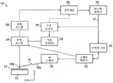
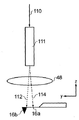
도 1은 본 발명의 실시예에 따라 z방향 작동 시스템을 포함하는 일례의 원자 힘 현미경의 구성요소를 개략적으로 나타낸 도면이다.
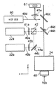
도 2는 탐침이 시료 표면을 가로질러 스캐닝하는 동안, 제1, 제2 및 제3레이저 빔이 탐침의 국소 영역에 입사하는 추적 시스템의 세부 사항을 나타내는, 도 1의 z방향 작동 시스템을 예시한 도면이다.
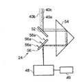
도 3은 도 2에 도시된 빔 스티어링 시스템의 확대도이다.
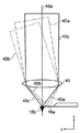
도 4는 외팔보에 3개의 빔을 집속하는 대물 렌즈의 확대도이다.
도 5는 4개의 분리된 광원에 의해 조명될 때의 상태이며, 위에서 보았을 때의 외팔보를 개략적으로 나타낸 도면이다.
도 6은 3개의 작동 빔의 변조 세기를 나타낸 도면이다.
도 7은 다른 탐침 구조 상의 z방향 작동 시스템의 3개의 빔의 바람직한 위치설정을 나타낸 도면이다.
도 8은 z방향 작동 시스템의 3개의 작동 빔의 바람직한 위치설정을 나타내는 선택형 열 바이모르프 탐침 설계의 개략도이다.
도 9는 AOM 또는 EOM을 포함하는 선택형 z방향 작동 시스템을 개략적으로 나타내는 도면이다.
도 10은 본 발명의 다른 실시예에 따른 현미경을 나타낸 도면이다.
도 11은 탐침의 래스터 스캐닝 동작을 나타낸 도면이다.
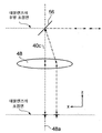
도 12는 거울의 회전축이 렌즈의 후방 초점면에 있는 구성을 나타낸다.
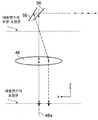
도 13은 거울의 회전축이 렌즈의 후방 초점면에 있지 않은 구성을 나타낸다.
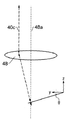
도 14는 거울이 회전 및 위치이동되는 구성을 나타낸다.
도 15-17은 검출 빔이 대물렌즈의 광축으로부터 오프셋된 검출 빔의 구성을 나타낸 도면이다.BRIEF DESCRIPTION OF THE DRAWINGS Figure 1 is a schematic representation of an exemplary atomic force microscope component including a z-directional actuation system in accordance with an embodiment of the present invention.
Figure 2 illustrates the z-directional actuation system of Figure 1, showing details of a tracking system in which the first, second and third laser beams are incident on the localized region of the probe while the probe is scanning across the sample surface FIG.
3 is an enlarged view of the beam steering system shown in Fig.
4 is an enlarged view of an objective lens for focusing three beams on a cantilever beam.
Fig. 5 is a schematic view of the cantilever beam as viewed from above when illuminated by four separate light sources. Fig.
FIG. 6 is a diagram showing modulation intensities of three operation beams. FIG.
Figure 7 is a diagram showing the preferred positioning of three beams of a z-direction operating system on another probe structure.
Figure 8 is a schematic diagram of a selectable thermal bimorph probe design illustrating the preferred positioning of the three actuation beams of the z-directional actuation system.
Figure 9 is a schematic representation of an optional z-direction operating system including an AOM or an EOM.
10 is a view showing a microscope according to another embodiment of the present invention.
11 is a diagram showing a raster scanning operation of the probe.
Figure 12 shows a configuration in which the rotational axis of the mirror is in the back focal plane of the lens.
13 shows a configuration in which the rotational axis of the mirror is not in the rear focal plane of the lens.
Fig. 14 shows a configuration in which the mirror is rotated and moved.
15-17 are views showing the configuration of a detection beam in which the detection beam is offset from the optical axis of the objective lens.
본 발명의 실시예를 첨부된 도면을 참조하여 설명한다. 본 발명에 따른 z방향 작동 시스템의 실시예를 포함하는 신규 현미경(10)을 도 1을 참조하여 도시했다. 현미경(10)은 탐침(16)에 의해 조사되는 시료(14)가 위에 장착된 스테이지(12)를 포함한다. 탐침(16)은 외팔보 빔(16a)과 팁(16b)을 포함하며, 상기 팁은 뾰족한 끝까지 경사지고, 외팔보 빔의 말단부를 향해 배치된다. 외팔보 빔의 다른(기부근방) 단부는 마운트에 고정된다. 마운트와 탐침(16)은 압전기 xy 드라이버(18)에 연결되며, 상기 드라이버는 시료(14)의 평면(x,y)을 가로질러 탐침(16)이 이동하도록 스캐닝 제어기(20)에 의해 동작 가능한 것이다.Embodiments of the present invention will be described with reference to the accompanying drawings. A
외팔보(16a)는 열 바이모르프로 지칭되는 타입의 것이다. 즉, 외팔보는 서로 다른 열팽창을 하는 2개(또는 그 이상)의 재료로 구성된다. 일반적으로 이것은 금 또는 알루미늄 코팅이 된 실리콘이나 실리콘 질화물 베이스가 될 것이다. 상기 코팅은 외팔보(16a)의 길이를 연장하며, 팁으로부터 뒷면을 덮는다.The
작동 광원(22)은 외팔보의 코팅된 측으로 추적 시스템(24)을 통해 향하게 되는 세기-변조된 방사 빔을 발생한다. 광의 파장은 코팅재료가 잘 흡수하는 것으로 선정한다. 광학 시스템(도시되지 않음)은 외팔보(16a) 상의 다른 구역으로 빔이 향하게 한다. 탐침 조명 및 소스 장치에 대한 옵션은 이하에서 상세히 논의될 것이다. 이 개요의 목적을 위해서는 바이모르프 탐침(16)이 외팔보의 굽힘을 유도하고, 팁의 z방향 위치를 조정하도록 조명된다고 이해하는 것으로 충분할 것이다.The working
검출 시스템(26)은 탐침 팁(16b)의 편향 각을 나타내는 탐침 동작 신호를 수집하도록 동작한다. 검출 시스템(26) 내에서, 검출 광원(도 1에 도시 않음)은 팁이 장착된 단부에서 외팔보 빔(16a)의 상부 면(뒷면)으로, 추적 시스템(24)을 통해 지향되는 광 빔을 방출한다. 외팔보의 뒷면으로부터 반사되는 광은 편향 검출기(도면을 명료하게 나타내기 위해 도시하지 않음), 일반적으로 분할 포토다이오드로 전해지며, 상기 검출기는 외팔보의 편향을 나타내는 출력을 발생한다. 외팔보의 뒷면에서 반사되는 광은 명료한 도시가 이루어지게 도 1, 또는 도 3a 또는 도 4에 도시하지 않았다. 검출 시스템의 출력은 프로세서(28)에 의해 분석되어 탐침의 진동 진폭에 관한 정보를 구한다. 프로세서(28)를 선택적으로 작동하여 탐침 위치, 예를 들어 편향 또는 위상을 나타내는 다른 매개변수를 구할 수 있다. 측정된 진동의 진폭에 응답하는 피드백 제어기(30)는 피드백 신호(31)를 출력하며, 상기 피드백 신호는 탐침-시료간 이격 거리를 조정하여 일정한 진동 진폭을 유지하기 위해 탐침 위치의 조정을 지시하는 데 사용된다. 이런 탐침 위치의 조정은 Z방향-위치 피드백으로 아래에서는 참고된다. 이미지 수집 프로세서(32)는 현미경(10)에 의해 얻어진 시료의 표면에 관한 정보를 나타내는 피드백 제어기(30)로부터 피드백 신호(31)를 수신하고, 이것은 xy 스캔 패턴에 대한 지식과 함께, 시료(14)의 맵을 구성하는 데 사용된다. 일반적으로, 피드백 신호와 그에 따른 맵은 시료(14)의 표면에 대한 높이 정보를 제공한다.The
상술한 바와 같이, 외팔보(16a)는 가열시 차등 팽창을 하는 재료로 이루어진 열 바이모르프 구조이다. 일 실시예에서, 외팔보(16a)는 알루미늄 코팅이 되었으며 실리콘 질화물로 제조된다. 작동 광원(22)은 최대 또는 피크가 특정 코팅을 위해 흡수 스펙트럼에 있는 1개 이상의 파장의 광을 방출한다. 예를 들어 파장은 ~ 810 nm 에 알루미늄 흡수 피크 근방에 있을 수 있다. 다른 코팅/파장 조합을 사용할 수 있으며, 예를 들면, 500nm 광 미만의 높은 흡수성을 갖는 금(gold)을 사용할 수 있다. 이 광이 외팔보(16a)의 코팅 측에 입사하는 경우, 알루미늄은 실리콘 질화물보다 더 큰 정도로 신장되며, 팁은 시료를 향하는 방향으로 하향하여 이동하도록 외팔보가 굽어진다. 조명 세기가 증가하게 되면, 그에 따라서 팁(16b)은 시료 표면에 가깝게 이동한다. 반대로, 조명 세기가 낮아지는 경우, 구부러짐이 감소되고, 팁(16b)은 시료로부터 멀어지는 방향으로 이동한다.As described above, the
명확히 다른 코팅 및 베이스 재료의 구성물은 조명에 대한 동일한 방향 또는 반대 방향으로 다른 수준의 구부러짐을 초래할 것이다. 작동 광원(22)은 신호 발생기(34)에 의해 제어되며, 상기 신호 발생기는 차례로, 피드백 제어기(30)에 연결된다. 따라서, 신호 발생기(34)를 작동하여 작동 광원(22)으로부터 방출되는 광의 세기를 제어할 수 있으며, 그것은 차례로(특정 재료와는 관계없이) 열 바이모르프 탐침에 의해 나타나는 굴곡 도를 판단하여, 스캐닝을 하는 과정에서 팁-시료 사이의 이격거리를 관리한다.Clearly different coatings and constructions of the base material will result in different levels of bending in the same or opposite direction to the illumination. The working
작동 광원(22)으로부터 방출되는 광의 세기는 후술되는 매개변수에 따라 수행되는 스캐닝 진행에 따라 변한다. 기본적으로, 작동 광원(22)은 2개의 다른 타입의 탐침 제어: 상술된 z방향 위치 피드백과 탐침 진동(아래에서 상세히 설명됨)을 위한 구동기구를 제공하는 것으로 고려될 수 있다. 즉, 탐침의 진동을 구동하고, 스캐닝을 진행하는 동안 탐침-시료간 이격거리를 조정하도록 설정된다.The intensity of the light emitted from the working
시료(14)의 이미지를 취하기 위해, 현미경은 다음과 같이 작동된다. 신호 발생기(34)는 원하는 주파수 및 진폭으로 진동하는 소스 신호를 제공한다. 이 신호는, 작동 광원(22)의 입력 시, 광원이 방출한 광 빔 중 하나의 빔이 신호 파형과의 관계로 그 세기를 변조하게 한다.In order to take an image of the
이 변조된 광이 외팔보(16a)에 입사되면, 광 세기의 변조로 변하는 외팔보의 굴곡을 초래한다. 따라서, 탐침 팁(16b)은, 자유 공간에서, 구동 신호의 것과 같은 주파수 및 진폭으로 시료를 향하거나 그로부터 멀어지는 방향으로 구동하게 된다. 이런 탐침 진동의 구동은 많은 원자 힘 현미경(AFM)의 용도에서 필요한 것이다. 동적 모드에서 작동하는 전형적인 AFM에서, 탐침 진동은 공진 또는 공진에 가까운 것일 수 있다. 선택적으로, 탐침은 탈(off)-공진이지만, 여전히 높은 주파수로 구동될 수 있다.When the modulated light is incident on the
작동 시, 탐침(16)은 상술한 바와 같이 변조된 세기의 광 빔에 의해 조사(irradiate)되며, 따라서 원하는 자유 공간의 진폭으로 진동한다. 다음, 신호 발생기(34)는, 예를 들어, 작동 광원(22) 중 하나에 대한 구동 신호를 증가시킨다. 이것은 아래에서 상세하게 설명된다. 어느 경우 든, 그 결과는 탐침 팁(16b)이 시료에 가까이 이동한다는 것이다. 팁이 표면 쪽으로 이동하여 표면과 상호 작용하여서, 탐침의 진동 진폭은 감소된다. 탐침의 움직임은 검출 시스템(26)을 사용하여 모니터링 된다. 검출 시스템(26)으로부터의 출력은 프로세서(28)에 전달되며, 프로세서는 검출기 신호로부터 진동의 진폭을 끌어낸다.In operation, the
피드백 제어기(30)는 탐침 진동의 관측된 진폭과 피드백 제어기(30)의 설정점의 진폭 사이의 차를 계산한다. 다음, 제어기(30)는 z방향 피드백 신호를 발생하며, 상기 신호는 이미지 수집 프로세서(32)에 의해 사용되어 시료 표면의 이미지를 구성한다. 또한, z방향 피드백 신호는 신호 발생기(34)에도 입력된다. 다음, 신호 발생기(34)는 지침 신호를 구동하여 1개의 작동 광원(22)으로 전송하여서 재변조된 출력을 생성한다. 재변조된 출력은 외팔보의 굴곡 패턴의 조절을 초래하며, 효과적으로 탐침 진동을 유지할 뿐만 아니라 피드백에 응답하여 팁의 Z방향 위치를 조정하기도 한다.The
xy 스캐너(18)는 일반적으로 래스터 패턴(raster pattern)을 동반하며, 시료의 표면을 가로질러 탐침 팁(16a)을 구동한다. 스캐닝 제어기(20)는 추적 시스템(24)이 스캐너(18)에 의해 구동되는 스캔 패턴에 부합하여 작동 소스(22)와 높이검출 시스템(26) 양쪽으로부터의 광이 그 이동 시에 탐침 상의 자신들의 위치를 유지하도록 보장한다. 스캐닝 제어기(20)는 자신들의 특정한 구조 및 기계적 동작에 따른 스캐너(18)와 추적 시스템(24)에 대한 서로 다른 구동 신호를 계산할 수 있다. 팁(16b)이, 예를 들면, 증가된 높이와 그 표면의 일부가 직면하게 되면, 팁의 동작은 변경되며, 모니터링된 매개변수, 예를 들어 탐침 진동의 진폭은 설정 점으로부터 멀어지는 방향으로 이동한다. 1개의 광원(22)에 의해 시료(14)로부터 광원이 멀어지게 이동하고, 검출기(28)로부터 수신된 신호를 그 설정점으로 귀환하게 제어하여서, 피드백 제어기(30)는 탐침 팁의 수직 위치를 조정하게 설정된다. 따라서, 탐침(16)은 표면과의 상호작용이(진동 수에 대한) 일정한 평균값을 갖는 위치에서 유지된다.The
도 2에서 Z방향 작동 시스템(22, 24, 34)의 기능 부분을 상세히 나타내었다. 이 예에서, 작동 광원(22)은 각각이 810nm 근방에서 동일한 적외선 파장의 광을 방출하는 제1 및 제2레이저(22a, 22b)를 포함한다. 제1레이저(22a)의 광(40a)은 수평적으로 편광되고, 제2레이저(22b)의 광(40b)은 수직적으로 편광된다. 양쪽 레이저(22a, 22b)가 방출하는 광의 출력 세기는 각각의 구동 신호를 통해 신호 발생기(34)가 제어하는 것과는 관계가 없다.The functional parts of the Z-
편광 빔 결합기(42)는 각각의 면(face)에 입사하는 2개의 광원에서 나오는 편광(40a, 40b)이 단일 출력 면에 출구를 향하게 배치된다. 특정적으로, 빔 결합기(42)는 빔(40b)의 S편광 성분을 반사하지만, 빔(40a)의 P편광 성분은 투과하는 빔(40a)에 대해 45°의 각도로 배치된 내부 거울(42a)을 갖는다.The
빔(40b)이 S편광이 되고 그리고 빔(40a)이 P편광이 되는 사실은 제한적이지 않은 구성이다. 어느 한 편광이 어느 한 빔으로, 또는 실질적으로 원형 편광으로 사용할 수도 있다. 필요한 모든 것은 그들이 빔 결합기에서 결합될 수 있도록 그들이 다른 편광으로 된다는 것이다.The fact that
제1전동 거울(44a)은 2개의 회전 직교 축에 대한 거울 작동기(44c)에 의해 조향가능 하여, 제2레이저(22b)로부터의 광(40b)이 필요한 각도와 위치에서 빔 결합기(42)에 유입하게 한다. 따라서, 제1거울(44a)을 조정하여 레이저 출력 빔(40a, 40b)이 결합기를 대체로 평행하거나 소량의 각도 차이로-이 각도 차이는 도 3 및 도 4에 명료하게 도시되었음-빠져나가게 한다. 또한, 높이 검출 시스템(26)에 사용하기 위한 제3레이저 빔(40c)도 적절한 광학체(도시되지 않음)에 의해 아래에서 논의되는 스티어링 거울 시스템(46)으로 향해지게 된다.The
제2전동 거울(44b)은 결합된 z방향 작동 빔(40a, 40b)이 추적 시스템(24)을 향하는 방향으로 지향되게 한다. 제2거울(44b)의 각도가 거울 작동기(44d)에 의해 2개의 직교 축에 대해 조정될 수 있어서, 레이저 출력 빔(40a, 40b)이 빔(40c)에 대해 작은 각도 차이를 갖고 추적 시스템(24)에 입사하여, 3개의 빔(40a, 40b, 40c)이 그 사이의 각도 차이가 작은 각도를 갖고 추적 시스템(24)에 입사한다. 탐침(16)이 xy스캐닝 시스템(18)에 의해 시료 표면을 가로질러 스캐닝하는 경우, 추적 시스템(24)은 3개의 빔(40a, 40b, 40c)이 탐침 xy 위치를 따르면서, 자신들의 상대적인 변위를 계속하여 유지하는 방식의 스캐닝을 한다.The second
추적 시스템(24)의 출사 시, 동시적으로 빔(40a, 40b, 40c)은 외팔보(16a)의 뒷면쪽으로 대물 렌즈(48)에 의해 집속된다. 빔(40a, 40b, 40c)이 다른 각도로 렌즈계(48)에 입사하여서, 그들은 외팔보(16a)의 각각의 횡방향으로 변위되는 구역에 집속된다.At the emergence of the
추적 시스템(24)의 세부 사항은 도 3a 및 도 3b에 도시되었다. 빔(40a, 40b, 40c)은 직각 블록(54) 쪽으로 고정된 거울(52)로부터 반사된다. 직각 블록은 빔(40c)이 입사 면에 수직적으로 입사하도록 지향되어 있다. 빔(40a, 40b, 40c)의 상대적 각도 변위는 직각 블록(54)에 의해 유지된다. 빔(40a, 40b, 40c)은 빔(40c)에 대한 일정한 각도로 배향된 조정가능한 거울(56)로 전달된다. 빔(40a, 40b, 40c)은 대물 렌즈(48) 쪽으로 거울(56)로부터 반사된다. 거울(56)은 3개의 압전 작동기 지주(56a)에 장착되며, 상기 지주(strut)들은 도 3a에 도시된 바와 같이 거울의 중심에서 원형으로 120°간격으로 떨어져 있다. 3개의 지주(56a)의 길이는 2직교 축에 대해 거울을 이동하면서 함께 조정되거나, 또는 거울을 회전하거나 기울이면서 다른 비율로 조정될 수 있다. 즉, 거울(56)의 각도는 거울(56)을 기울여서 2직교 축에 대해 조정할 수 있다. 2직교 축에 대한 회전의 제어는 독립적으로 수행할 수 있다. 거울(56)을 기울여서, 반사된 빔(40a, 40b, 40c)을 함께 회전시켜, 각각의 빔의 입사각 및 입사점이 대물 렌즈(48)를 횡방향으로 가로질러 이동하게 한다. 거울(56)의 동조(synchronisation)는 탐침(16)에 따르는 스캐닝 패턴의 기울임이며, 그것은 xy 스캐너(18)에 의한 구동은 입사 빔(40a, 40b, 40c) 각각이 탐침 상에서 자신들의 위치를 유지하는 것을 의미한다. 탐침에서의 빔(40a, 40b, 40c)의 위치는 렌즈(48) 쪽으로의 빔의 입사각(입사점이 아님)에 의해서만 결정되어서, 탐침 상의 초점 사이의 간격은 렌즈로의 입사점의 변경으로 변하지 않는다.Details of the
이런 추적 시스템(24)은 4개, 5개, 또는 그 이상의 광 빔이 무빙 외팔보를 추적하게 하는데 채택될 수 있음을 당업자는 예측할 수 있을 것이다.Those skilled in the art will appreciate that such a
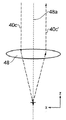
도 4는 외팔보(16a) 상의 각각의 스폿에 빔(40a, 40b, 40c)을 집속하는 대물 렌즈(48)를 개략적으로 나타낸 도면이다. 렌즈(48)가 도 4에서 단 1개 만의 렌즈 요소로 도시되어 있지만, 그것은 다수의 렌즈 요소의 조립체를 포함할 수 있는 것으로 이해한다. 상술한 바와 같이, 거울(44a, 44b)은 빔(40a, 40b, 40c)이 렌즈의 광축(48a)에 대한 서로 다른 입사각으로 대물 렌즈(48)에 입사하도록 배치된다. 도 4에 도시된 바와 같이, 이것은 빔(40a, 40b, 40c)이 그 길이를 따라 서로 다른 구역에 탐침 쪽으로 대물 렌즈(48)에 의해 집속되는 결과를 초래한다. 이 예에서, 빔(40c)은 광축(48a)과 평행하다. 상기 빔(40a, 40b, 40c)의 각각은 대물 렌즈(48)의 입사동(entrance pupil)의 직경의 1/4 보다 큰 직경을 갖는 것에 주의한다.4 schematically shows an
광학 시스템은 무한 광학 시스템이며, 따라서 빔(40a, 40b, 40c)은 이들이 대물 렌즈(48)에 입사할 때 모두 수집되며, 탐침 상의 스폿 위치는 오직 대물 렌즈(48)에 입사하는 수집된 빔의 각도에만 따르고, 그 횡방향 위치에는 따르지 않는다. 선택적으로, 시준(collimation) 렌즈(41a, 41b)는, 필요한 경우, 빔(40a, 40b)을 수집하기 위해 제공될 수 있다. 무한 광학 시스템(infinity optical system)은 이러한 렌즈(41a, 41b)의 위치가 외팔보에 스폿을 형성하는데 영향을 주지 않고 조정되고 광학 성분이 더해질 수 있기 때문에 바람직한 것이다. 다른 실시예(도시되지 않음)에서, 광학 시스템은 각각의 빔이 렌즈(48)에 입사하여 분산(divergent)되는 유한 광학 시스템(finite optical system)이다.The optical system is an infinite optical system so that the
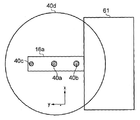
도 5는 빔(40a-c)에 의해 조명된 외팔보(16a) 상의 스폿을 개략적으로 나타낸 도면이다. 스폿의 중심은 간격을 두고 떨어져 있으며, 스폿은 겹쳐져 있지 않다. 도 5는 또한 도 2에 도시된 비전(vision) 시스템 광원(60)에 의해 방출되는 빔(40d)에 의해 조명되는 대형 영역도 나타낸 것이다. 이 광원(60)은 비전 시스템의 일부이며, 스캔 수행에 앞서 탐침(16)과 빔의 광학적 정렬이 이루어진다. 비전 시스템은 또한 광원(60)으로부터 떨어져서, CCD 카메라(61), 부분적 반사 거울, 및 튜브 렌즈(41)를 포함하며, CCD에 이미지를 형성한다. 외팔보(16a)는 기판(61)에 장착되며, 위에서(z 방향) 보고 나타낸 것이다.Figure 5 is a schematic representation of a spot on a
외팔보의 자유 말단부 근방에 제1스폿은 검출 레이저 빔(40c)의 입사 위치에 있다. 검출 레이저 빔(40c)은 비-변조된 빔이며, 상기 빔은 탐침 팁이 시료 표면과 상호 작용하여 탐침의 뒷면의 편향을 검출하는데 사용된다. 따라서, 외팔보의 반대편 측에서, 팁(16b) 부근에 위치하여야 한다. 팁(16b)은 대부분의 외팔보 설계에서 외팔보의 자유 말단부를 향해 있고, 마찬가지로 검출 레이저 빔(40c)도 자유 말단부를 향하는 방향으로 입사된다.The first spot near the free end of the cantilever beam is at the incident position of the
빔(40a)은 탐침의 편향을 이동시켜(즉, Z방향 피드백 신호(31)에 따라 스캐닝을 하는 과정에서 탐침-시료간 이격 거리를 조종하여), 자유 말단부와 기부근방 단부/기판(61) 사이에 위치한 제2스폿에 외팔보(16a)를 조명하게 배치된다. 빔(40b)은 스캐닝을 하는 과정에서 탐침의 진동을 구동하고, 외팔보(16a)와 기판(61)의 계면 근방에서 외팔보의 기부근방 단부에 입사된다. 빔(40a, 40b)에 의해 형성된 스폿은 유사한 크기로 나타나지만, 진동 및 편향 빔의 조명 영역은 다를 수 있다.The
도시된 구역이 바람직하다 하더라도, 진동 빔(40b) 및 편향 빔(40a)이 도시된 것과는 다른 외팔보 상의 위치에 입사될 수 있다. 특히, 외팔보의 진동이 탐침 외팔보의 베이스(기부근방 단부)와 기판(61) 근방을 향하는 방향으로 진동 빔(40b)을 향하게 하여서 매우 효과적으로 여기 된다. 이것은 외팔보의 기계적 진동을 효과적으로 구동할 수 있게 한다.Even though the depicted section is preferred, the
대형의 제4스폿은 설치하는 동안 외팔보를 보는 데 사용되는 카메라(60)용 조명 빔(40d)이다. 이것은 선택적으로 시료를 스캐닝하는 동안 오프로 전환할 수 있다.The large fourth spot is the
도 3에 나타낸 추적 시스템(24)은 모두 4개의 빔(40a-d)을 함께 추적하도록 배치되며, 상기 빔들은 종방향으로 정렬이 유지된다. 이런 방식으로 형성하여, 상기 빔들은 계속하여, 탐침이 스캐닝하는 과정에서 이동하여, 동일한 상대적 배향으로, 외팔보(16a)를 조명한다.The
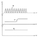
도 6은 3개의 빔(40a-c)의 세기 변조(intensity modulation)를 나타낸 그래프이다. 진동 빔(40b)의 세기는 제1구동 신호에 따른 신호 발생기(34)에 의해 조절되며, 그 신호는 일반적으로 수 십(10) kHz 내지 수 MHz 범위의 일정 주파수에 사인파(90)이며, 특정 사항은 현미경 구조, 작동 모드 및 특정 외팔보에 따른다. 제1구동 신호에 의해 생성된 탐침 팁(16b)의 진동의 최대 진폭은 일반적으로 10-200nm 정도이다. 편향 빔(40a)의 세기는 제2구동 신호에 따른 신호 발생기(34)에 의해 변조되어 탐침의 일정한 진동 진폭을 유지하며, 탐침의 팁(16b)은 시료의 프로파일을 추적할 수 있고, 이 경우에 탐침의 팁(16b)은 시료의 계단을 통과하여 '91'에서 제2구동 신호로 변한다. 전형적으로, 계단은 수 마이크로(microns) 정도의 크기로 이루어져서, 제2구동 신호에 의해 발생하는 탐침 팁(16b)의 편향 진폭은 일반적으로 제1구동 신호에 의해 발생하는 탐침 팁의 편향 진폭보다 어느 정도 더 큰 크기(즉, 적어도 10배 더 큰 크기)이다. 검출 레이저 빔(40c)은 일정한 세기(92)를 갖도록 변조되지 않는다.Figure 6 is a graph showing the intensity modulation of the three
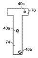
도 7은 다른 탐침 형상을 나타낸 도면이다. 이런 구성에서, 외팔보는 베이스로부터 자유단부까지 연장되는 종방향 아암(74)과 자유단부에 횡방향 바아(76)를 갖고, T자 형상으로 형성된다. 이 평면도에서 볼 수 없더라도, 팁은 횡방향 바아(76)에 비대칭적으로 위치하여, 그에 의해 지지되어 있는 것을 의미한다. 이런 방식에서, 오프셋 팁은 시료 표면을 향하여 그로부터 멀어지는 방향으로 수직적으로 이동하는 작은 원호를 나타낸다. 뒤틀림 진동(torsional oscillation)에 의해서, 외팔보는 그 종축에 대해 진동하여 비틀림 운동을 수행하게 된다. 따라서, T자 형상의 탐침의 뒤틀림 진동은 표준 직사각형 탐침의 굴곡 진동으로 교체하여 사용할 수 있다. 7 is a view showing another probe shape. In this configuration, the cantilevers are formed in a T-shape with a
뒤틀림 진동에 의해 확립되는 수직 팁 동작은 고속 스캐닝 현미경에 사용되는 경우, 다른 모드를 능가하는 여러 이점을 제공한다. 뒤틀림 공진은 굴곡 공진보다 높은 공진 주파수에 있다. 이상적으로, 뒤틀림 진동 주파수는 0.5 - 5 MHz 부근에 있고, 굴곡 탄성 상수는 0.2 - 2 Nm-1(이들 매개변수는 외팔보의 치수를 조정하여 제어될 수 있음) 정도이다. 이것은 시료되는 표면에서의 비율이 뒤틀림 작동용 보다 높다는 것을 의미한다. 따라서, 스캐닝 속도를 증가하거나, 또는 팁-시료 상호작용 힘의 검출 감도를 향상시키는데 사용할 수 있다. 동적 이미지에서 직면하는 다른 문제에는 때때로, 피드백 시스템에서의 대형 에러(예를 들면, 표면 높이의 급격한 변화로부터 제기되는 에러)가 굴곡 굽힘(편향)이 시료-탐침 베이스 간격에서의 에러를 수용하도록 증가할 때 표면에 인가되는 대형 힘을 초래할 수 있는 것이 있다. 진동의 뒤틀림 모드를 사용하여 동적 진동을 제공하는 것은 굴곡 굽힘의 강성(stiffness)이 동적 기능성의 손실 없이 감소 될 수 있는 것을 의미한다. 이것은 인가된 표면 힘에 에러의 영향력을 줄이고, 굴곡 굽힘이 뒤틀림 모드에 더하여 필요한 경우, 탐침의 더 큰 변위를 제공한다.The vertical tip motion established by the torsional vibration provides several advantages over other modes when used in a high-speed scanning microscope. The torsional resonance is at a higher resonance frequency than the torsional resonance. Ideally, the torsional vibration frequency is in the vicinity of 0.5 - 5 MHz and the flexural modulus is in the order of 0.2 - 2 Nm -1 (these parameters can be controlled by adjusting the dimensions of the cantilever). This means that the ratio at the surface to be sampled is higher than for the twist operation. Thus, it can be used to increase the scanning speed, or to improve the detection sensitivity of the tip-sample interaction force. Other problems encountered in dynamic images are that sometimes large errors in the feedback system (e.g., errors resulting from abrupt changes in surface height) cause the bending bending to increase to accommodate errors in the sample- There is something that can result in large forces applied to the surface. Providing dynamic vibration using the twisting mode of vibration means that the stiffness of the flexural bending can be reduced without loss of dynamic functionality. This reduces the influence of the error on the applied surface force and provides a greater displacement of the probe, if necessary, in addition to flexure bending mode.
도 5의 직사각형의 탐침 설계와 같이, 3개의 간격을 두고 떨어져 있는 레이저 빔이 뒤틀림 진동을 여기하도록 T자형 탐침의 뒷면에 집속된다. 이전과 같이, 검출 레이저 빔(40c)은 탐침의 팁 위에 스폿에 집속된다. 탐침 팁이 횡방향 바아(76)를 따라 오프셋 되어서, 그렇게 검출 스폿(40c)도 있게 된다. 진동 빔(40b)은 다시 효과적인 결합을 보장하기 위해 탐침과 기판 사이의 계면에서의 외팔보(74)의 기부근방 단부에 집속된다. 그러나 이 실시예에서, 스폿(40b)은 외팔보 종축의 우측으로 오프셋으로 되어 있다. 오프셋(offset) 위치는 뒤틀림 진동을 가장 잘 여기하는 것으로 확인되었다. 제3빔(40a)은 다시 검출 및 진동 빔 사이의 외팔보 상에서 중심에 집속된다.As in the rectangular probe design of Figure 5, three spaced apart laser beams are focused on the back surface of the T-shaped probe to excite the torsional vibration. As before, the
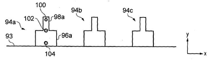
도 8은 본 발명의 Z방향 작동 시스템에 응답하는 탐침의 다른 설계를 도시한다. 이 실시예에서, 기판(93)은 3개의 탐침(94a-c) 어레이를 지지한다. 각 탐침은 기판에서 넓은 영역(96a)과 자유 단부까지 연장되는 좁은 영역(98a)을 갖는다. 양측 영역(96a, 98a)은 기초재료와는 다른 열 팽창성을 가진 재료로 코팅된다.Figure 8 illustrates another design of the probe in response to the Z-directional actuation system of the present invention. In this embodiment, the
이 실시예에서, 팁의 위치 위에 있는 제1조명 스폿(100)은 검출 레이저에 의해 형성되었다. 이 스폿(100)은 탐침 이동을 구동하지 않는다. 제2스폿(102)은 외팔보의 2개의 섹션(96a, 98a) 사이의 계면에 집속된다. 이 계면은 또한 광열 에너지가 기계적인 진동을 여기하는 효과적인 결합 부위이다. 이 스폿(102)은 탐침 진동을 구동하는 레이저에 따른다. 제3스폿(104)은 기판(92) 쪽으로 탐침의 섹션(96a)에 집속된다. 이 레이저 빔은 탐침 선택에 대한 응답성이 있다. 즉, 탐침(94a-c) 중 하나에 집속되어, 그것을 다른 탐침의 평면으로부터 하향하여 낮추고, 그 탐침을 선택하여 스캐닝을 수행한다. 이전과 마찬가지로, 빔 추적 시스템은 모든 빔이 시료를 가로질러 스캐닝하기 때문에 탐침에 대해 고정된 위치를 유지하게 한다. 제1실시예에서의 시료의 프로파일을 따르는 탐침의 편향은 편향 빔(40a)에 의해 구동된다. 도 8의 경우, 이 프로파일 편향은 스폿(100, 102) 사이에 제4스폿(도시되지 않음)에 의해; 스폿(104)(그 탐침 선택 기능에 더하여)에 의해; 또는 압전 작동기와 같은 다른 작동 메커니즘에 의해 구동될 수 있다.In this embodiment, the
도 9는 오직 1개의 변조된 빔(110)만이 상기와 같이 2개의 변조된 빔(40a,b)을 대신하여 사용되는 다른 광학 장치를 나타낸다. 이 예에서, 렌즈(48) 내로의 빔(110)의 입사 각도는 상기 탐침 상의 서로 다른 2개의 구역에서 빔(110)으로 탐침를 순차적으로 조명하도록, 변조기(111)에 의해 2개의 각도(112, 114) 사이에서 절환된다. 변조기(111)는 전기광학 변조기 또는 음향광학 변조기가 바람직하다. 변조기(111)는 주파수적으로 충분하게 각도를 절환할 수 있어서, 탐침을 각각의 각도에서 조명 사이클 사이에서 심하게 냉각하지 않는다. 예를 들어, 탐침 상의 구역 사이에 절환 시간은 탐침 상의 구역의 열 시간 상수(thermal time constant)보다 작은 것이 바람직하다. 빔(110)이 각도(112)로 지향하는 경우, 탐침을 편향하여 시료의 프로파일을 따르게 조절되며, 각도(114)로 지향하는 경우, 탐침을 진동하도록 조절된다.9 shows another optical device in which only one modulated
상기 예에서, 빔(110)은 빔에 의해 다루어지는 구역과 동조하여 변조된다. 즉, 빔(110)이 각도(112)로 지향될 때, 제1변조가 인가되어 빔의 세기를 변화시키며, 그리고 빔(110)이 각도(114)로 지향될 때, 제2변조가 인가되어 빔의 세기를 변화시킨다. 다른 실시예에서는, 빔(110)의 세기가 변조되지 않고, 대신에 2개의 구역의 가열 양이 펄스 폭 변조와 유사한 방식으로, 각 구역에 빔을 보내는 시간의 양을 제어하여 변조된다. 즉, 빔이 2개의 구역 사이를 절환(switch)하여서, 각 구역에서 보내는 시간의 양이 시간이 지남에 따라 변할 수 있어서, 각 구역으로 전달되는 평균 파워가 변할 것이다. 2개의 구역이 독립적으로 변조될 수 있도록, 상기 빔은 또한 절환 사이클의 일부로 제3구역으로 지향하기도 하며, 상기 제3구역은 탐침을 벗어나거나 탐침의 일부와 무열적 반응(no thermal response)을 한다.In this example, the
또 다른 예에서, 빔(110)의 변조는 빔에 의해 다루어지는 구역과 동조하여 변화하지 않을 수 있다. 이 예에서, 빔(110)은 2개의 구역을 다르게 가열할 목적 이외에 넓은 영역에 걸쳐 에너지를 분배하기 위한 목적으로 외팔보의 표면 위에 연속적으로 스캐닝 된다. 빔(110)의 세기는(예를 들어 탐침을 진동할 목적으로) 표면 위를 스캐닝할 때 변조되지만, 빔(110)의 세기가 스캐닝 동작에 동조하여 변조되지는 않는다. 즉, 제1구동 신호에 따른 구역의 제1구역 및 제2구동 신호에 따른 구역의 제2구동 구역에서 변조되지 않고 - 오히려 빔의 각도와 상관없이 단일 구동 신호(예를 들어 일정 주파수의 사인파) 만에 따라 변조된다.In another example, the modulation of
설명의 편의를 위해, 도 9의 실시예에서는 검출 빔을 나타내지 않았다. 그러나 검출 빔은 또한 도 2에 도시된 다양한 다른 추가 항목과 함께 소용될 수 있는 것이다. 변조기(111)는 도 2의 항목(42, 44a, 44c)을 대체한다. 따라서, 추적 시스템(24)은 변조기(111)로 대체되지 않고, 따라서 거울(56)이 계속하여 사용되어서 탐침의 래스터 스캐닝 동작을 추적하는 데 사용된다.For convenience of explanation, the detection beam is not shown in the embodiment of Fig. However, the detection beam can also be used with various other additional items shown in Fig. The
언급한 바와 같이, 종래의 AFM 스캐닝을 하는 과정에서 Z방향으로의 탐침 동작은 2개의 성분: 탐침-시료 상호작용을 모니터링하는 데 사용되는 진동 성분과, 피드백 신호에 응답하여 탐침-시료간의 간격 거리를 조정하는데 사용되는 Z방향 위치설정 성분을 포함하여, 평균 상호작용의 세기가 일정 수준으로 유지되게 한다. 본 발명의 실시예(도 1)에서, 단일 작동 시스템을 사용하여 Z방향으로의 모든 탐침 움직임을 구동한다. 구동 신호의 피드백 성분을 사용하여 이미지를 구성한다.As mentioned above, in the course of conventional AFM scanning, the probe motion in the Z direction has two components: a vibration component used to monitor the probe-sample interaction, and a vibration component used to monitor the probe- Direction positioning component used to adjust the intensity of the average interaction to maintain a constant level of intensity. In an embodiment of the present invention (Fig. 1), a single actuation system is used to drive all probe movements in the Z direction. The image is constructed using the feedback component of the drive signal.
상술한 실시예에서, 높이 검출 시스템(26)은 탐침의 각도를 측정하는 광학 레버를 사용하여 편향 검출에 기초한다. 다른 높이 탐지 시스템, 예를 들어 간섭계에 기초한 시스템도 사용될 수 있다. 그런 검출 시스템은 레이저 빔과 참조 빔을 방출하는 광원을 포함하며, 레이저 빔은 외팔보의 팁 단부의 상부 표면에 집속되며, 기준 빔은 스테이지의 상부 표면으로부터 반사된다. 반사 시에, 이런 광 빔은 간섭계를 포함하는 탐침 높이 검출기로 전달된다. 레이저 광은 간섭 패턴이 외팔보로부터 반사되는 광과 참조 빔 사이에서 발생되는 충분한 가간접성(coherent) 이다. 이것은 경로 차의 측정 또는 2개의 빔 사이의 경로 차의 변화 및 그에 따른 스테이지 표면 위의 외팔보의 뒷면의 순간 높이의 시도(indication)를 나타낸다.In the above-described embodiment, the
도 4, 6 및 7의 탐침 팁 상의 스폿(40c)의 위치는 특히 바람직하게는, 검출 시스템(16)이 탐침 팁의 높이를 직접 측정하는 간섭계 검출 시스템인 경우에 바람직하다. 그러나, 검출 시스템(16)이 탐침의 각도를 측정하는 광학 레버이고, 검출 스폿(40c)의 위치가 덜 중요한 경우이면, 예를 들어 도 6의 경우에서와 같이 T자형 탐침용으로 횡방향 바아(76)를 가로질러 임의 장소에 배치할 수 있다.The position of the
도 10은 도 1-5의 현미경과 함께 다수의 특징부를 가진 현미경을 나타낸 도면이며, 동일한 도면 번호는 상응하는 구성요소를 지칭하는 데 사용된다. 도 1-5의 현미경과 다른 점은 다음과 같다.Figure 10 shows a microscope with a number of features in conjunction with the microscope of Figures 1-5, wherein like reference numerals are used to refer to corresponding components. The differences from the microscope of Fig. 1-5 are as follows.
도 1의 압전 XY 스캐너(18)는 Z 방향뿐만 아니라 X 및 Y 방향으로도 탐침을 이동할 수 있는 압전 탐침 드라이버(18a)로 대체된다. 드라이버(18a)는 구동 신호(50)에 의해 구동되며, 간섭계, 용량 센서 또는 LVDT 센서와 같은 센서(도시하지 않음)가 작동기(18a)의 위치를 검출하여 피드백 신호(51)를 제공하며, 스캐닝 제어기(20)를 사용하여 원하는 위치로 드라이버(18a)가 탐침을 구동하도록 피드백 루프의 구동 신호(50)를 조정할 수 있다. 추적 시스템(24)의 거울(56)은 탐침 드라이버(18a)에 의해 야기되는 탐침의 XY 이동을 추적하도록 빔이 이동하게 배치된다.The
마찬가지로, 추적 시스템(24)의 틸팅 거울(56)은 구동 신호(52)에 의해 구동되며, 간섭계, 정전용량 센서, 스트레인 게이지 또는 LVDT 센서 등의 센서(도시되지 않음)는 거울(56)의 위치를 검출하여 피드백 신호(53)를 제공하며, 스캐닝 제어기(20)를 사용하여 원하는 위치에 거울(56)이 위치하도록 피드백 루프의 구동 신호(52)를 조정할 수 있다.The tilting
현미경은 또한 Z 방향뿐만 아니라 X 및 Y 방향으로도 렌즈(48)를 이동할 수 있는 렌즈(48)에 부착된 압전 렌즈 드라이버(54)도 갖는다. 렌즈 드라이버(54)는 구동 신호(55)에 의해 구동되며, 간섭계, 정전용량 센서, 스트레인 게이지 또는 LVDT 센서와 같은 센서(도시되지 않음)는 렌즈(48)의 위치를 검출하여 피드백 신호(56)를 제공하며, 스캐닝 제어기(20)를 사용하여 렌즈 드라이버(54)가 렌즈를 원하는 위치로의 이동을 보장하는 피드백 루프의 구동 신호(56)를 조정할 수 있다. 렌즈 드라이버(54)는 X, Y, Z방향으로 탐침 드라이버(54)에 의해 야기되는 탐침의 움직임을 추적하도록 렌즈(48)가 위치이동하게 배치된다.The microscope also has a
또한, 음향광학 변조기(AOM)(57)가 제공되어 검출 시스템(26)으로부터의 검출 빔(40c)의 각도를 조정한다. AOM(57)을 작동하여 외팔보(16) 상의 2개 이상의 지점 사이에서 검출 빔(40c)을 절환하여서, 동작의 다른 모드를 검출하거나, 또는 다른 이유로, 예를 들어 2개의 구역에서의 탐침의 높이 또는 각도(예를 들어 외팔보의 베이스를 향하는 방향 및 외팔보의 팁을 향하는 방향)를 검출한다. 이 절환동작은 시료가 (예를 들어 래스터(raster) 라인 사이 또는 픽셀 사이) 스캐닝 될 때 발생하거나 또는 동일한 시료의 2개의 일관된 스캔 사이에서 발생할 수 있다.In addition, an acousto-optic modulator (AOM) 57 is provided to adjust the angle of the
도 3a의 실시예에서, 탐침 팁의 추적동작은 틸팅 거울(56)에 의해 단독으로 수행된다. 이 구조는 대물 렌즈(48)의 수용 각도로 인하여 제한된 스캔 범위를 갖는다. (일반적으로, 5 미크론 이상이 양호하며, 10 미크론 이상이 더욱 양호하며, 통상적으로 수십 미크론 이상이 가장 양호한) 큰 스캔 범위를 위해서는 다른 팁 추적 수단을 사용하는 것이 바람직하다. 이것은 (고속 스캔을 이룰 수 있지만 스캔 범위가 제한되는) 틸팅 거울(56)과 조합되는 (큰 스캔 범위를 달성하지만 저속 스캔을 하는) 압전 렌즈 드라이버(54)가 가진 XY평면에 대물 렌즈(48)를 위치이동하여, 도 10의 현미경에서 달성될 수 있다. 이런 중첩 방식은 특정 유형의 검사에 필요한 훨씬 더 큰 스캔 범위를 달성할 수 있다.In the embodiment of Figure 3A, the tracking operation of the probe tip is performed solely by the tilting
이런 중첩 방식의 예를 도 11에 도시했다. 지그재그의 실선(58)은 XY평면에서 탐침의 래스터 스캐닝 동작을 예시했다. 일점 쇄선(59)은 렌즈(48)의 동작에 의해 방사 빔에 부여된 정현파 저주파수 동작을 나타낸다. (특히, 래스터 스캐닝 동작(58)이 각각의 선의 끝에서 급변하는 고주파 동작에서) 방사 빔의 XY 동작의 나머지는 거울(56)의 회전에 의해 빔에 부여된다.An example of such a superposition method is shown in Fig. A zigzag
도 11의 중첩 탐침 추적 방법은 다음과 같이 설정할 수 있다. 먼저, 탐침이 예를 들어 오직 거울(56)에 의해 추적되기에 충분히 작은, 소 동작 범위로 스캐닝되는 래스터 패턴에 따라 이동된다. 거울(56)은 정적으로 유지되는 렌즈(48)와 같이 회전하며, 스캐닝 탐침 상의 스폿의 위치는 비전 시스템(60, 61)을 통해 확인된다. 다음, 거울 구동 신호(52)를 조정하여, 스폿은 탐침 상의 위치를 변경하지 않고, 무빙 탐침을 정확하게 추적한다. 그 후, 거울(56)의 동작은 정지되고, 렌즈(48)가 유사한 방식으로 탐침의 움직임을 추적하기 위해 위치이동되며, 렌즈 구동 신호(55)는 스폿이 비전 시스템(60, 61)을 통해 관측되게 조정된다. 렌즈 및 거울 구동 신호가 상술한 바와 같이 설정되고 나면, 이들은 도 11에 도시된 중첩된 운동을 달성하기 위해 동시적으로 작동될 수 있다.The overlapping probe tracking method of FIG. 11 can be set as follows. First, the probe is moved in accordance with a raster pattern that is scanned into a small motion range, small enough, for example, to be tracked by the
일반적으로, 탐침의 Z방향 동작은 렌즈(48)의 초점 심도보다 작지만 큰 스캔에 대한 것이어서, 시료의 높이에 큰 변화가 있을 수 있고, 스캐닝 동안 렌즈 드라이버(54)도 탐침이 초점 평면에 유지되도록 시료로부터 (z방향으로) 멀어지는 방향으로 또는 렌즈(48)를 향하는 방향으로 위치이동하게 작동할 수 있을 것이다.Generally, the Z-directional motion of the probe is less than the depth of focus of the
도 12 및 도 13은 조정 가능한 거울(56)의 회전축을 대물 렌즈(48)의 초점에 바람직하게 배치하고, 거울 평면에 조정 가능한 거울(56)의 회전축을 배치하며, 거울(56)을 사용하여 검출 빔(40c)이 탐침으로 향하게 하는 상태를 나타낸 도면이다. 도 12-17에서는 도면을 간략하게 도시할 목적으로 검출 빔(40c) 만을 나타내었다. 그러나, 동일한 대물 렌즈(48)를 통해 도 1에 도시된 바와 같이 탐침은 작동 빔으로 조명될 수도 있다.Figures 12 and 13 illustrate that the rotational axis of the
도 12 및 도 13에서, 탐침은 렌즈(48)의 전방 초점면에 있다. 도 12의 경우, 거울(56) 및 그 회전축은 렌즈(48)의 후방 초점(즉, 렌즈의 광축이 그 후방 초점면과 교차하는 지점)에 위치하지만, 도 13의 경우는 거울과 그 회전축이 후방 초점면에서 오프셋되어 있다.In Figures 12 and 13, the probe is in the front focal plane of the
도 12에서는 검출 빔이 렌즈(48)의 광축과 동축이고 직각으로 탐침에 부딪치면, 반사된 빔이 거울(56)에 의한 반사 전 및 후와 동일한 경로를 따라 귀환하는 것을 볼 수 있다. 만일 거울(56)이 회전되어 검출 빔(40c)이 더 이상 렌즈(48)의 광축과 동축이지 않으면, 탐침과 거울(56)에 의해 반사된 빔은 이동(shift)하지 않을 것이다. 이 경우, 거울(56)은 탐침를 추적하기 위해 (위치이동이 없는) 순수 회전으로 이동될 수 있다.In Fig. 12, when the detection beam is coaxial with the optical axis of the
도 13에서는 검출 빔이 렌즈(48)의 광축과 동축이고 직각으로 탐침에 부딪치면, 반사된 빔은 거울(56)에 의한 반사 전 및 후와 동일한 경로를 따라 귀환하는 것을 볼 수 있다. 거울(56)에 의한 반사 후의 반사된 빔의 경로는 '80'으로 나타내었다. 만일 거울(56)이 회전되어 탐침을 조명하는 검출 빔이 더 이상 렌즈(48)의 광축과 동축이지 않으면, 탐침과 거울(56)에 의해 반사되어진 빔은 위치(80)로부터 위치(81)로 이동한다. 이 이동은 반사된 빔의 이동 또는 횡방향 위치가 반사된 빔의 각도와 그에 따른 탐침의 각도를 측정하는데 사용되는 경우, 예를 들어 WO2009/147450에 기재된 바와 같이 일반적으로 분할 포토다이오드 검출 시스템을 사용하여, 반사된 빔의 횡방향 변위의 측정으로 탐침의 각도를 결정하는 경우에 특히 바람직하지 않다.In Fig. 13, when the detection beam is coaxial with the optical axis of the
특정 경우에, 대물 렌즈(48)의 구성은 대물 렌즈(48)의 후방 초점면에 조정가능한 거울(56)의 회전축을 위치할 수 없게 할 수 있다. 이런 경우, 거울(56)은 도 13에 도시된 바와 같이 반사된 빔이 이동하지 않도록 회전될 수 있을 뿐만 아니라 위치이동될 수도 있다. 예를 들어 도 14는 거울(56)이 회전 및 위치이동된 상태를 나타내었으며, 반사된 빔은 거울(56)에 의해 반사된 빔이 반사되어진 후, 조명 빔과 동일한 경로를 따른다.In certain cases, the configuration of the
도 4에서, 외팔보(16)는 수평으로 놓여있는 상태(즉, 그 길이가 Y방향으로 연장되는 상태)로 도시되었다. 또한, 검출 빔(40c)의 중심은 도 4에 도시된 바와 같이 렌즈(48)의 광축(48a)과 동축에 있다. 그러나, 일반적으로는 탐침(16)이 도 15에 도시된 바와 같이 Y축에 대해 예각(θ)으로 하향하여 연장되며, 검출 빔(40c)은 도 15 및 도 16에 도시된 바와 같이 X 및 Y방향으로 광축(48a)으로부터 오프셋으로 있다. 도 17은 Z축을 따라 나타난 모습이며, 광축(48a)으로부터 빔(40c, 40c')의 X 및 Y오프셋을 나타낸 렌즈(48)를 도시한 도면이다.In Fig. 4, the
도 16에 도시한 바와 같이 광축(48a)으로부터 X방향으로 조명 빔(40c)을 오프셋하여, 반사된 빔(40c')이 조명 빔(40c)과 동일한 경로를 따라 귀환하지 않게 한다. 이것은 광학적으로 조명 빔(40c)으로부터 분리할 필요가 없이 검출기를 향하는 방향으로 반사된 빔(40c')이 매우 용이하게 향하게 만들기 때문에 바람직하다.The
본 발명이 하나 이상의 바람직한 실시예를 참조하여 설명되었지만, 본 발명은 다양한 변경이나 변형이 첨부된 청구범위에서 한정된 본 발명의 범위를 벗어나지 않고 이루어질 수 있는 것으로 한다.
While the present invention has been described with reference to one or more preferred embodiments, it is intended that the present invention be capable of modifications and alterations without departing from the scope of the invention as defined by the appended claims.
Claims (24)
방사 빔을 수신하여, 그것을 탐침 쪽을 향하게 배치된 렌즈와; 시간이 지남에 따라 빔이 그 광축에 대한 각으로 렌즈에 입사하는 입사각을 변화시키기 위한 스캐닝 시스템을 포함하는 것을 특징으로 하는 장치.An apparatus for illuminating a probe of a probe microscope, said apparatus comprising:
A lens that receives the radiation beam and directs it toward the probe; Characterized in that it comprises a scanning system for changing the angle of incidence of the beam with respect to its optical axis to the lens over time.
상기 장치는 탐침을 구동하기 위한 작동 시스템이며, 부가로 방사 빔의 세기를 변조하기 위한 변조 시스템을 포함하는 것을 특징으로 하는 장치.The method according to claim 1,
Wherein the apparatus is an actuation system for driving a probe, and further comprising a modulation system for modulating the intensity of the radiation beam.
상기 빔은 탐침으로부터 반사되어 반사된 검출 빔을 생성하는 검출 빔이며, 상기 장치는 부가로 상기 탐침으로부터 반사된 검출 빔을 수신하고 상기 반사된 검출 빔으로부터 탐침의 이동을 검출하게 배치된 검출 시스템을 포함하는 것을 특징으로 하는 장치.The method according to claim 1,
The beam is a detection beam that is reflected from the probe and produces a reflected detection beam, the apparatus further comprising a detection system arranged to receive the detection beam reflected from the probe and detect movement of the probe from the reflected detection beam Lt; / RTI >
스캐닝 시스템은 탐침의 이동을 추적하도록 상기 빔을 이동하게 배치된 추적 시스템인 것을 특징으로 하는 장치.4. The method according to any one of claims 1 to 3,
Wherein the scanning system is a tracking system arranged to move the beam to track movement of the probe.
탐침이 시료 표면을 가로질러 이동하게 작동할 수 있는 탐침 드라이버를 부가로 포함하며, 상기 추적 시스템은 드라이버에 의해 야기되는 탐침의 이동을 추적하도록 빔이 그 광축에 대한 각도로 렌즈에 입사하는 입사각을 시간이 지남에 따라 변하게 배치되는 것을 특징으로 하는 장치.5. The method of claim 4,
Further comprising a probe driver operable to cause the probe to move across the surface of the sample, the tracking system comprising an angle of incidence at which the beam is incident on the lens at an angle relative to its optical axis to track the movement of the probe caused by the driver And is arranged to vary over time.
스캐닝 시스템은 렌즈를 향해 빔을 반사하는 빔 스티어링 거울; 및 빔 스티어링 거울을 회전시키기 위한 거울 작동기를 포함하는 것을 특징으로 하는 장치.6. The method according to any one of claims 1 to 5,
The scanning system includes a beam steering mirror for reflecting the beam towards the lens; And a mirror actuator for rotating the beam-steering mirror.
상기 렌즈는 작동 방사 빔을 수신하여 그것이 탐침으로 향하게 배치되며; 상기 장치는 부가로 작동 방사 빔의 세기를 변조하기 위한 변조 시스템을 포함하고; 상기 빔 스티어링 거울은 검출 빔과 렌즈를 향하는 작동 방사 빔을 모두 반사하는 것을 특징으로 하는 장치.The method according to claim 3 or 6,
The lens receiving an actinic radiation beam and directing it towards the probe; The apparatus further comprises a modulation system for modulating the intensity of the actuation radiation beam; Wherein the beam steering mirror reflects both the detection beam and the actuation radiation beam towards the lens.
상기 스캐닝 시스템은 전기광학 변조기 또는 음향광학 변조기를 포함하는 것을 특징으로 하는 장치.8. The method according to any one of claims 1 to 7,
Wherein the scanning system comprises an electro-optical modulator or an acousto-optic modulator.
상기 렌즈를 위치이동하기 위한 렌즈 드라이버를 부가로 포함하는 것을 특징으로 하는 장치.9. The method according to any one of claims 1 to 8,
And a lens driver for moving the lens.
상기 렌즈 드라이버는 탐침 드라이버에 의해 야기되는 탐침의 이동을 추적하도록 렌즈를 위치이동하게 배치된 것을 특징으로 하는 장치.10. The method according to claim 5 or 9,
Wherein the lens driver is arranged to position the lens to track movement of the probe caused by the probe driver.
상기 스캐닝 시스템은 탐침이 시료로부터 정보를 획득할 때 빔이 그 광축에 대한 각도로 렌즈에 입사하는 입사각이 시간이 지남에 따라 변하게 배치된 것을 특징으로 하는 장치.11. The method according to any one of claims 1 to 10,
Wherein the scanning system is arranged such that the angle of incidence at which the beam enters the lens at an angle to its optical axis when the probe acquires information from the sample changes over time.
상기 탐침은 빔이 탐침을 가열하여 탐침이 광열효과에 의해 변형될 수 있게 배치된 서로 다른 열팽창 계수를 갖는 2개의 물질을 포함하는 것을 특징으로 하는 현미경.13. The method of claim 12,
Wherein the probe comprises two materials having different coefficients of thermal expansion arranged such that the beam heats the probe and the probe is deformable by the photothermal effect.
방사 빔을 생성하는 단계; 렌즈가 빔을 수신하는 단계; 탐침쪽으로 렌즈의 빔을 향하게 하는 단계; 및 빔이 그 광축에 대한 각도로 입사하는 입사각을 시간이 지남에 따라 변하게 하는 단계를 포함하는 것을 특징으로 하는 방법.A method of illuminating a probe of a probe microscope, said method comprising:
Generating a radiation beam; The lens receiving the beam; Directing the beam of the lens toward the probe; And changing the angle of incidence of the beam at an angle relative to its optical axis over time.
상기 방법은 탐침을 구동하는 방법이며, 상기 방법은 부가로 방사 빔의 세기를 변조하는 단계도 포함하는 것을 특징으로 하는 방법.15. The method of claim 14,
Wherein the method is a method of driving a probe, the method further comprising modulating the intensity of the radiation beam.
상기 빔은 탐침을 가열하여, 탐침이 광열효과에 의해 변형되는 것을 특징으로 하는 방법.16. The method according to claim 14 or 15,
Wherein the beam heats the probe such that the probe is deformed by the photothermal effect.
탐침을 이동시키는 단계와; 상기 탐침의 이동을 추적하도록 빔의 입사각을 시간이 지남에 따라 변화시키는 단계도 포함하는 것을 특징으로 하는 방법.17. The method according to any one of claims 14 to 16,
Moving the probe; Further comprising the step of varying the angle of incidence of the beam over time to track the movement of the probe.
상기 탐침은 시료의 전체 표면을 이동하고, 상기 빔의 세기는 시료 표면의 프로파일을 따르도록 변조되는 것을 특징으로 하는 방법.18. The method according to any one of claims 14 to 17,
Wherein the probe moves over the entire surface of the sample and the intensity of the beam is modulated to follow the profile of the surface of the sample.
빔이 그 광축에 대한 각도로 렌즈에 입사하는 입사각이 탐침 상의 서로 다른 구역으로 빔의 중심이 순차적으로 향하게 변하는 것을 특징으로 하는 방법.19. The method according to any one of claims 14 to 18,
Characterized in that the angle of incidence at which the beam is incident on the lens at an angle relative to its optical axis changes sequentially to the center of the beam into different regions on the probe.
상기 빔은 반사된 검출 빔을 생성하기 위해 탐침으로부터 반사되는 검출 빔이며, 상기 방법은 부가로 탐침으로부터 반사된 검출 빔을 수신하여 반사된 검출 빔으로부터의 탐침의 이동을 검출하는 단계도 포함하는 것을 특징으로 하는 방법.The method according to claim 14 or 19,
The beam is a detection beam reflected from the probe to produce a reflected detection beam, the method further comprising the step of receiving the detection beam reflected from the probe and detecting movement of the probe from the reflected detection beam Lt; / RTI >
상기 검출 빔은 반사된 검출 빔으로부터 다른 동작 모드를 검출하기 위해 탐침 상의 서로 다른 구역으로 순차적으로 향하게 하는 것을 특징으로 하는 방법.21. The method according to claim 19 or 20,
Wherein the detection beam sequentially directs the reflected detection beam to different zones on the probe to detect different modes of operation.
상기 렌즈에서 작동 방사 빔을 수신하여 그것을 탐침으로 향하게 하는 단계; 작동 방사 빔의 세기를 변조하는 단계; 및 작동 방사 빔이 그 광축에 대한 각도로 렌즈에 입사하는 입사각을 시간이 지남에 따라 변화하는 단계도 포함하는 것을 특징으로 하는 방법.22. The method according to claim 20 or 21,
Receiving an actinic radiation beam from the lens and directing it to the probe; Modulating the intensity of the actuation radiation beam; And the step of varying the incident angle at which the working radiation beam is incident on the lens at an angle relative to its optical axis over time.
탐침에 의해 스캐닝된 시료로부터 정보를 획득하는 단계도 포함하며, 상기 탐침이 시료로부터 정보를 획득할 때, 빔이 그 광축에 대한 각도로 렌즈에 입사하는 입사각이 변하는 것을 특징으로 하는 방법.23. The method according to any one of claims 14 to 22,
Further comprising the step of acquiring information from a sample scanned by the probe, wherein when the probe acquires information from the sample, the angle of incidence at which the beam is incident on the lens at an angle to the optical axis changes.
상기 렌즈를 위치이동시키는 단계도 포함하는 것을 특징으로 하는 방법.
24. The method according to any one of claims 14 to 23,
And moving the lens. ≪ Desc / Clms Page number 13 >
Applications Claiming Priority (3)
| Application Number | Priority Date | Filing Date | Title |
|---|---|---|---|
| GBGB1201640.8A GB201201640D0 (en) | 2012-01-31 | 2012-01-31 | Photothermal probe actuation |
| GB1201640.8 | 2012-01-31 | ||
| PCT/GB2013/050195 WO2013114100A1 (en) | 2012-01-31 | 2013-01-29 | Beam scanning system |
Publications (1)
| Publication Number | Publication Date |
|---|---|
| KR20140129047A true KR20140129047A (en) | 2014-11-06 |
Family
ID=45876391
Family Applications (2)
| Application Number | Title | Priority Date | Filing Date |
|---|---|---|---|
| KR1020147023443A KR20140129047A (en) | 2012-01-31 | 2013-01-29 | Beam scanning system |
| KR1020147023440A KR20140129046A (en) | 2012-01-31 | 2013-01-29 | Probe actuation |
Family Applications After (1)
| Application Number | Title | Priority Date | Filing Date |
|---|---|---|---|
| KR1020147023440A KR20140129046A (en) | 2012-01-31 | 2013-01-29 | Probe actuation |
Country Status (6)
| Country | Link |
|---|---|
| US (2) | US9291641B2 (en) |
| EP (2) | EP2810083B1 (en) |
| JP (3) | JP6224009B2 (en) |
| KR (2) | KR20140129047A (en) |
| GB (1) | GB201201640D0 (en) |
| WO (2) | WO2013114100A1 (en) |
Cited By (2)
| Publication number | Priority date | Publication date | Assignee | Title |
|---|---|---|---|---|
| KR20200019205A (en) * | 2017-06-28 | 2020-02-21 | 인피니트시마 리미티드 | Scanning probe microscope |
| KR20210022917A (en) * | 2019-08-21 | 2021-03-04 | 경북대학교 산학협력단 | High-speed atomic force microscope |
Families Citing this family (21)
| Publication number | Priority date | Publication date | Assignee | Title |
|---|---|---|---|---|
| GB201201640D0 (en) * | 2012-01-31 | 2012-03-14 | Infinitesima Ltd | Photothermal probe actuation |
| DE102013227105A1 (en) * | 2013-09-03 | 2015-03-05 | Leica Microsystems Cms Gmbh | Microscope and acousto-optical beam combiner for a microscope |
| JP6241999B2 (en) * | 2014-02-21 | 2017-12-06 | 国立大学法人金沢大学 | Cantilever for scanning probe microscope and scanning probe microscope |
| EP2913681A1 (en) | 2014-02-28 | 2015-09-02 | Infinitesima Limited | Probe system with multiple actuation locations |
| EP2913682A1 (en) * | 2014-02-28 | 2015-09-02 | Infinitesima Limited | Probe actuation system with feedback controller |
| EP3308172B1 (en) | 2015-06-12 | 2023-08-02 | Infinitesima Limited | Scanning probe system with two prove drivers |
| EP3368933B1 (en) * | 2015-11-01 | 2024-01-03 | Howard Hughes Medical Institute | Large field of view, high resolution microscope |
| CN109313076A (en) * | 2016-06-03 | 2019-02-05 | 株式会社岛津制作所 | Infrared spectrophotometer |
| GB201610128D0 (en) | 2016-06-10 | 2016-07-27 | Infinitesima Ltd | Scanning probe system with multiple probes |
| DE102016221319A1 (en) * | 2016-10-28 | 2018-05-03 | Carl Zeiss Smt Gmbh | A scanning probe microscope and method for increasing a scanning speed of a scanning probe microscope in the step-in scanning mode |
| US10761189B1 (en) * | 2016-11-23 | 2020-09-01 | Alakai Defense Systems, Inc. | Method for detecting a distant target and measuring the target distance using inelastically scattered light |
| WO2018109803A1 (en) * | 2016-12-12 | 2018-06-21 | オリンパス株式会社 | Atomic force microscope |
| US10302764B2 (en) * | 2017-02-03 | 2019-05-28 | Microsoft Technology Licensing, Llc | Active illumination management through contextual information |
| US10107834B2 (en) | 2017-03-20 | 2018-10-23 | Infinitesima Limited | Measurement system |
| DE102017205528B4 (en) | 2017-03-31 | 2021-06-10 | Carl Zeiss Smt Gmbh | Device and method for a scanning probe microscope |
| JP7179826B2 (en) * | 2017-08-03 | 2022-11-29 | ブルカー ナノ インコーポレイテッド | Thermally stable and drift resistant probe for scanning probe microscope and method of manufacture |
| EP3543712A1 (en) * | 2018-03-21 | 2019-09-25 | Nederlandse Organisatie voor toegepast- natuurwetenschappelijk onderzoek TNO | Method and system for at least subsurface characterization of a sample |
| US10768225B1 (en) * | 2019-03-08 | 2020-09-08 | Advanced Micro Devices, Inc. | Probe placement for laser probing system |
| GB201915539D0 (en) | 2019-10-25 | 2019-12-11 | Infinitesima Ltd | Method of imaging a surface using a scanning probe mircoscope |
| US20210333219A1 (en) * | 2020-04-27 | 2021-10-28 | Mpi Corporation | Method of determining distance between probe and wafer held by wafer probe station |
| US11644478B2 (en) | 2021-02-03 | 2023-05-09 | Oxford Instruments Asylum Research, Inc. | Automated optimization of AFM light source positioning |
Family Cites Families (19)
| Publication number | Priority date | Publication date | Assignee | Title |
|---|---|---|---|---|
| US8087288B1 (en) * | 1993-08-17 | 2012-01-03 | Bruker Nano, Inc. | Scanning stylus atomic force microscope with cantilever tracking and optical access |
| US5581082A (en) * | 1995-03-28 | 1996-12-03 | The Regents Of The University Of California | Combined scanning probe and scanning energy microscope |
| US5861550A (en) | 1997-10-14 | 1999-01-19 | Raymax Technology, Incorporated | Scanning force microscope |
| US6330824B1 (en) | 1999-02-19 | 2001-12-18 | The University Of North Carolina At Chapel Hill | Photothermal modulation for oscillating mode atomic force microscopy in solution |
| JP2000266658A (en) * | 1999-03-16 | 2000-09-29 | Seiko Instruments Inc | Multiprobe and scanning probe microscope |
| JP2002005810A (en) * | 2000-06-16 | 2002-01-09 | Canon Inc | Probe and its manufacturing method, surface-observing device, exposing device, and information-processing device |
| JP2003134853A (en) * | 2001-10-24 | 2003-05-09 | Minolta Co Ltd | Drive unit using electromechanical transducing element, and apparatus applying the element |
| US7230719B2 (en) * | 2003-12-02 | 2007-06-12 | National University Of Singapore | High sensitivity scanning probe system |
| JP2005331509A (en) * | 2004-04-19 | 2005-12-02 | Japan Science & Technology Agency | Method and device for measuring object by variable natural oscillation cantilever |
| US7358822B2 (en) | 2005-01-21 | 2008-04-15 | Cornell Research Foundation, Inc. | MEMS oscillator drive |
| JP2006329973A (en) * | 2005-04-28 | 2006-12-07 | Hitachi Ltd | Scanning probe microscope, sample observing method using the same, and device manufacturing method |
| EP1898204B1 (en) * | 2005-05-31 | 2018-09-12 | National University Corporation Kanazawa University | Scanning probe microscope and cantilever drive device |
| JP4810251B2 (en) * | 2006-02-16 | 2011-11-09 | キヤノン株式会社 | Atomic force microscope |
| US7748260B2 (en) | 2006-07-12 | 2010-07-06 | Veeco Instruments Inc. | Thermal mechanical drive actuator, thermal probe and method of thermally driving a probe |
| US7770231B2 (en) | 2007-08-02 | 2010-08-03 | Veeco Instruments, Inc. | Fast-scanning SPM and method of operating same |
| JP2009128139A (en) * | 2007-11-22 | 2009-06-11 | Hitachi Ltd | Scan probe microscope, and probe unit for the scan probe microscope |
| KR101488059B1 (en) | 2008-06-06 | 2015-01-29 | 인피니트시마 리미티드 | Probe detection system |
| JP6117705B2 (en) | 2011-01-31 | 2017-04-19 | インフィニテシマ リミテッド | Adaptive mode scanning probe microscope |
| GB201201640D0 (en) * | 2012-01-31 | 2012-03-14 | Infinitesima Ltd | Photothermal probe actuation |
-
2012
- 2012-01-31 GB GBGB1201640.8A patent/GB201201640D0/en not_active Ceased
-
2013
- 2013-01-29 US US14/375,552 patent/US9291641B2/en active Active
- 2013-01-29 EP EP13707024.9A patent/EP2810083B1/en active Active
- 2013-01-29 WO PCT/GB2013/050195 patent/WO2013114100A1/en active Application Filing
- 2013-01-29 EP EP13705228.8A patent/EP2810082B1/en active Active
- 2013-01-29 JP JP2014555308A patent/JP6224009B2/en active Active
- 2013-01-29 KR KR1020147023443A patent/KR20140129047A/en not_active Application Discontinuation
- 2013-01-29 KR KR1020147023440A patent/KR20140129046A/en not_active Application Discontinuation
- 2013-01-29 JP JP2014555307A patent/JP6216329B2/en active Active
- 2013-01-29 US US14/375,622 patent/US9222958B2/en active Active
- 2013-01-29 WO PCT/GB2013/050194 patent/WO2013114099A1/en active Application Filing
-
2017
- 2017-10-04 JP JP2017193953A patent/JP6495406B2/en not_active Expired - Fee Related
Cited By (2)
| Publication number | Priority date | Publication date | Assignee | Title |
|---|---|---|---|---|
| KR20200019205A (en) * | 2017-06-28 | 2020-02-21 | 인피니트시마 리미티드 | Scanning probe microscope |
| KR20210022917A (en) * | 2019-08-21 | 2021-03-04 | 경북대학교 산학협력단 | High-speed atomic force microscope |
Also Published As
| Publication number | Publication date |
|---|---|
| EP2810083B1 (en) | 2020-08-19 |
| KR20140129046A (en) | 2014-11-06 |
| WO2013114100A1 (en) | 2013-08-08 |
| EP2810082B1 (en) | 2020-03-18 |
| US20150020244A1 (en) | 2015-01-15 |
| GB201201640D0 (en) | 2012-03-14 |
| US9291641B2 (en) | 2016-03-22 |
| JP6216329B2 (en) | 2017-10-18 |
| US20150013035A1 (en) | 2015-01-08 |
| JP6495406B2 (en) | 2019-04-03 |
| US9222958B2 (en) | 2015-12-29 |
| JP2015505616A (en) | 2015-02-23 |
| EP2810083A1 (en) | 2014-12-10 |
| JP2015505617A (en) | 2015-02-23 |
| EP2810082A1 (en) | 2014-12-10 |
| JP6224009B2 (en) | 2017-11-01 |
| JP2018021930A (en) | 2018-02-08 |
| WO2013114099A1 (en) | 2013-08-08 |
Similar Documents
| Publication | Publication Date | Title |
|---|---|---|
| JP6495406B2 (en) | Beam scanning system | |
| US9410982B2 (en) | Photothermal actuation of a probe for scanning probe microscopy | |
| US8528110B2 (en) | Probe detection system | |
| EP0674200B1 (en) | Scanning near-field optic/atomic force microscope | |
| US5835251A (en) | Scanner system | |
| EP2891117B1 (en) | Multiple probe detection and actuation | |
| JP2020112566A (en) | Probe system having plurality of actuation locations | |
| EP2890989A1 (en) | Multiple probe actuation | |
| JP2023015071A (en) | Scanning probe system for controlling tilt angle of probe chip | |
| JP2009128139A (en) | Scan probe microscope, and probe unit for the scan probe microscope | |
| US9383386B2 (en) | Optical beam positioning unit for atomic force microscope | |
| US7962966B2 (en) | Scanning probe microscope having improved optical access | |
| JPH06229753A (en) | Scanner system | |
| CN117616288A (en) | Multi-probe microscope illumination system |
Legal Events
| Date | Code | Title | Description |
|---|---|---|---|
| WITN | Withdrawal due to no request for examination |