KR20140128564A - Audio system and method for sound localization - Google Patents
Audio system and method for sound localization Download PDFInfo
- Publication number
- KR20140128564A KR20140128564A KR1020130047056A KR20130047056A KR20140128564A KR 20140128564 A KR20140128564 A KR 20140128564A KR 1020130047056 A KR1020130047056 A KR 1020130047056A KR 20130047056 A KR20130047056 A KR 20130047056A KR 20140128564 A KR20140128564 A KR 20140128564A
- Authority
- KR
- South Korea
- Prior art keywords
- signal
- channel
- speaker
- sound
- position information
- Prior art date
Links
Images


Classifications
-
- G—PHYSICS
- G10—MUSICAL INSTRUMENTS; ACOUSTICS
- G10L—SPEECH ANALYSIS OR SYNTHESIS; SPEECH RECOGNITION; SPEECH OR VOICE PROCESSING; SPEECH OR AUDIO CODING OR DECODING
- G10L19/00—Speech or audio signals analysis-synthesis techniques for redundancy reduction, e.g. in vocoders; Coding or decoding of speech or audio signals, using source filter models or psychoacoustic analysis
- G10L19/008—Multichannel audio signal coding or decoding using interchannel correlation to reduce redundancy, e.g. joint-stereo, intensity-coding or matrixing
-
- H—ELECTRICITY
- H04—ELECTRIC COMMUNICATION TECHNIQUE
- H04S—STEREOPHONIC SYSTEMS
- H04S3/00—Systems employing more than two channels, e.g. quadraphonic
-
- H—ELECTRICITY
- H04—ELECTRIC COMMUNICATION TECHNIQUE
- H04S—STEREOPHONIC SYSTEMS
- H04S3/00—Systems employing more than two channels, e.g. quadraphonic
- H04S3/008—Systems employing more than two channels, e.g. quadraphonic in which the audio signals are in digital form, i.e. employing more than two discrete digital channels
-
- H—ELECTRICITY
- H04—ELECTRIC COMMUNICATION TECHNIQUE
- H04S—STEREOPHONIC SYSTEMS
- H04S7/00—Indicating arrangements; Control arrangements, e.g. balance control
- H04S7/30—Control circuits for electronic adaptation of the sound field
- H04S7/302—Electronic adaptation of stereophonic sound system to listener position or orientation
- H04S7/303—Tracking of listener position or orientation
-
- H—ELECTRICITY
- H04—ELECTRIC COMMUNICATION TECHNIQUE
- H04R—LOUDSPEAKERS, MICROPHONES, GRAMOPHONE PICK-UPS OR LIKE ACOUSTIC ELECTROMECHANICAL TRANSDUCERS; DEAF-AID SETS; PUBLIC ADDRESS SYSTEMS
- H04R2499/00—Aspects covered by H04R or H04S not otherwise provided for in their subgroups
- H04R2499/10—General applications
- H04R2499/13—Acoustic transducers and sound field adaptation in vehicles
-
- H—ELECTRICITY
- H04—ELECTRIC COMMUNICATION TECHNIQUE
- H04S—STEREOPHONIC SYSTEMS
- H04S2400/00—Details of stereophonic systems covered by H04S but not provided for in its groups
- H04S2400/03—Aspects of down-mixing multi-channel audio to configurations with lower numbers of playback channels, e.g. 7.1 -> 5.1
-
- H—ELECTRICITY
- H04—ELECTRIC COMMUNICATION TECHNIQUE
- H04S—STEREOPHONIC SYSTEMS
- H04S2400/00—Details of stereophonic systems covered by H04S but not provided for in its groups
- H04S2400/11—Positioning of individual sound objects, e.g. moving airplane, within a sound field
-
- H—ELECTRICITY
- H04—ELECTRIC COMMUNICATION TECHNIQUE
- H04S—STEREOPHONIC SYSTEMS
- H04S2420/00—Techniques used stereophonic systems covered by H04S but not provided for in its groups
- H04S2420/01—Enhancing the perception of the sound image or of the spatial distribution using head related transfer functions [HRTF's] or equivalents thereof, e.g. interaural time difference [ITD] or interaural level difference [ILD]
-
- H—ELECTRICITY
- H04—ELECTRIC COMMUNICATION TECHNIQUE
- H04S—STEREOPHONIC SYSTEMS
- H04S7/00—Indicating arrangements; Control arrangements, e.g. balance control
Landscapes
- Engineering & Computer Science (AREA)
- Physics & Mathematics (AREA)
- Signal Processing (AREA)
- Acoustics & Sound (AREA)
- Multimedia (AREA)
- Mathematical Physics (AREA)
- Computational Linguistics (AREA)
- Health & Medical Sciences (AREA)
- Audiology, Speech & Language Pathology (AREA)
- Human Computer Interaction (AREA)
- Stereophonic System (AREA)
Abstract
Description
본 발명은 객체 오디오 신호 처리 방법 및 장치에 관한 것으로, 보다 상세하게는 객체 오디오 신호의 부호화 및 복호화하거나 3차원 공간에 렌더링하기 위한 방법 및 장치에 관한 것이다.
The present invention relates to a method and apparatus for processing an object audio signal, and more particularly, to a method and apparatus for encoding and decoding an object audio signal or rendering the object audio signal in a three-dimensional space.
3D 오디오란 기존의 서라운드 오디오에서 제공하는 수평면 상의 사운드 장면(2D)에 높이 방향으로 또 다른 축(dimension)을 제공함으로써, 말그대로 3차원 공간에서의 임장감있는 사운드를 제공하기 위한 일련의 신호처리, 전송, 부호화, 재생 기술 등을 통칭한다. 특히, 3D 오디오를 제공하기 위해서는 종래보다 많은 수의 스피커를 사용하거나 혹은 적은 수의 스피커를 사용하더라도 스피커가 존재하지 않는 가상의 위치에서 음상이 맺히도록 하는 렌더링 기술이 널리 요구된다. 3D audio is a series of signal processing to provide a lively sound in a three-dimensional space, by providing another dimension in the height direction on a horizontal sound scene (2D) provided by existing surround audio, Transmission, encoding, reproduction technology, and the like. Particularly, in order to provide 3D audio, a rendering technique is widely required in which an image is formed at a virtual position where a speaker is not used even if a larger number of speakers are used or a smaller number of speakers are used.
3D 오디오는 향후 출시될 초고해상도 TV (UHDTV)에 대응되는 오디오 솔루션이 될 것으로 예상되며, 고품질 인포테인먼트 공간으로 진화하고 있는 차량에서의 사운드를 비롯하여 그밖에 극장 사운드, 개인용 3DTV, 테블릿, 스마트폰, 클라우드 게임 등 다양하게 응용될 것으로 예상된다.
3D audio is expected to become an audio solution for future high-definition TVs (UHDTVs), and it is expected that 3D audio will be able to be used in a variety of applications such as sound in vehicles evolving into high-quality infotainment space as well as theater sound, personal 3DTV, tablet, Games and so on.
3D 오디오는 우선 최대 22.2채널까지 종래보다 많은 채널의 신호를 전송하는 것이 필요한데, 이를 위해서는 이에 적합한 압축 전송 기술이 요구된다. 종래의 MP3, AAC, DTS, AC3 등의 고음질 부호화의 경우, 주로 5.1채널 미만의 채널만을 전송하는데 최적화되어 있었다. For 3D audio, it is necessary to transmit signals of more than 22.2 channels, which is a conventional compression transmission technique. In the case of conventional high-quality encoding such as MP3, AAC, DTS, and AC3, it is optimized to transmit only channels less than 5.1 channels.
또한 22.2채널 신호를 재생하기 위해서는 24개의 스피커 시스템을 설치한 청취공간에 대한 인프라가 필요한데, 시장에 단기간 확산이 용이하지 않으므로, 22.2채널 신호를 그보다 작은 수의 스피커를 가진 공간에서 효과적으로 재생하기 위한 기술, 반대로 기존 스테레오 혹은 5.1채널 음원을 그보다 많은 수의 스피커인 10.1채널, 22.2채널 환경에서 재생할 수 있도록 하는 기술, 나아가서, 규정된 스피커 위치와 규정된 청취실 환경이 아닌 곳에서도 원래의 음원이 제공하는 사운드 장면을 제공할 수 있도록 하는 기술, 그리고 헤드폰 청취환경에서도 3D 사운드를 즐길 수 있도록 하는 기술 등이 요구된다. 이와 같은 기술들을 본원에서는 통칭 렌더링(rendering)이라고 하고, 세부적으로는 각각 다운믹스, 업믹스, 유연한 렌더링(flexible rendering), 바이노럴 렌더링 (binaural rendering) 등으로 부른다.In addition, in order to reproduce 22.2 channel signals, an infrastructure for a listening space in which 24 speaker systems are installed is required. In short, it is not easy to spread to the market, so a technology for effectively reproducing 22.2 channel signals in a space with a smaller number of speakers , A technique that allows the reproduction of a conventional stereo or 5.1 channel sound source in a larger number of speakers, 10.1 channel and 22.2 channel environment, and also a sound provided by the original sound source A technique for providing a scene, and a technique for enabling 3D sound to be enjoyed in a headphone listening environment. Such techniques are referred to herein as collective rendering and are referred to in detail as downmix, upmix, flexible rendering, binaural rendering, and the like.
한편, 이와 같은 사운드 장면을 효과적으로 전송하기 위한 대안으로 객체 기반의 신호 전송 방안이 필요하다. 음원에 따라서 채널 기반으로 전송하는 것보다 객체 기반으로 전송하는 것이 더 유리한 경우가 있을 뿐 아니라, 객체 기반으로 전송하는 경우, 사용자가 임의로 객체들의 재생 크기와 위치를 제어할 수 있는 등 인터렉티브한 음원 청취를 가능하게 한다. 이에 따라 객체 신호를 높은 전송률로 압축할 수 있는 효과적인 전송 방법이 필요하다. On the other hand, an object-based signal transmission scheme is needed as an alternative for efficiently transmitting such a sound scene. It is more advantageous to transmit on an object basis than on a channel-based transmission according to a sound source. In addition, when transmitting on an object basis, the user can arbitrarily control the reproduction size and position of the objects, . Accordingly, there is a need for an effective transmission method capable of compressing object signals at a high transmission rate.
또한, 상기 채널 기반의 신호와 객체 기반의 신호가 혼합된 형태의 음원도 존재할 수 있으며, 이를 통해 새로운 형태의 청취 경험을 제공할 수도 있다. 따라서, 채널 신호와 객체 신호를 함께 효과적으로 전송하고, 이를 효과적으로 렌더링하기 위한 기술도 필요하다. In addition, a sound source in which the channel-based signal and the object-based signal are mixed may exist, thereby providing a new type of listening experience. Accordingly, there is a need for a technique for effectively transmitting a channel signal and an object signal together and rendering the same effectively.
마지막으로 채널이 갖는 특수성과 재생단에서의 스피커 환경에 따라 기존의 방식으로는 재생하기 어려운 예외 채널들이 발생할 수 있다. 이 경우 재생단에서의 스피커 환경을 기반으로 효과적으로 예외 채널을 재현하는 기술이 필요하다.
Finally, depending on the specificity of the channel and the speaker environment at the playback stage, exception channels that are difficult to reproduce in the conventional manner may occur. In this case, there is a need for a technique for effectively reproducing the exception channel based on the speaker environment at the reproduction end.
본 발명의 일 양상에 따르면, 적어도 한 개의 예외 채널 신호와 복수 개의 일반 채널 신호가 포함된 비트열을 수신하는 단계; 상기 예외 채널 신호 및 복수 개의 일반 채널 신호를 복호화하는 단계; 상기 예외 채널 신호와 상기 복수개의 일반 채널 신호의 상관도 정보를 생성하는 단계; 상기 상관도 정보를 참조하여 적어도 두가지 다운믹스 방법 중 한가지 다운믹스 방법을 선택하는 오디오 신호 처리 방법; 상기 선택된 다운믹스 방법을 이용하여 상기 예외 채널 신호를 복수 개의 채널신호로 다운믹스 하는 단계를 포함하는 오디오 신호처리 방법이 제공될 수 있다.
According to an aspect of the present invention, there is provided a method for transmitting a signal, the method comprising: receiving a bit stream including at least one exception channel signal and a plurality of general channel signals; Decoding the exception channel signal and a plurality of general channel signals; Generating correlation information between the exception channel signal and the plurality of general channel signals; An audio signal processing method for selecting one downmix method among at least two downmix methods by referring to the correlation information; And downmixing the exception channel signal into a plurality of channel signals using the selected downmix method.
본 발명에 의하면, 연속적으로 움직이는 신호에 대하여 사용자가 컨텐츠의 의도와 다르게 불연속적으로 인지되는 문제를 해결한다. 본 발명은 사용자의 생리학적 특징을 반영하여 사용자 개개인에게 맞는 가중함수를 이용하여 선택적을 이 문제를 해결하는 효과를 가진다. 본 발명의 효과가 상술한 효과들로 제한되는 것은 아니며, 언급되지 아니한 효과들은 본 명세서 및 첨부된 도면으로부터 본 발명이 속하는 기술분야에서 통상의 지식을 가진 자에게 명확히 이해될 수 있을 것이다.
According to the present invention, a problem that a user continuously recognizes a discontinuous signal different from the intention of a content is solved for a signal which is continuously moving. The present invention has the effect of solving this problem selectively by using a weight function suitable for each user reflecting the physiological characteristics of the user. The effects of the present invention are not limited to the above-mentioned effects, and the effects not mentioned can be clearly understood by those skilled in the art from the present specification and the accompanying drawings.
도 1은 동일한 시청 거리에서 영상 크기에 따른 시청 각도를 설명하기 위한 도면
도 2는 멀티 채널의 일 예로서 22.2ch의 스피커 배치 구성도
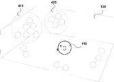
도 3은 청자가 3D 오디오를 청취하는 청취 공간상에서의 각 사운드 객체들의 위치를 나타내는 개념도
도 4는 도 3에 도시된 객체들에 대해 본 발명에 따른 그룹핑 방법을 이용하여 객체신호그룹을 형성한 예시적 구성도
도 5는 본 발명에 따른 객체 오디오 신호의 부호화기의 일 실시예에 대한 구성도
도 6는 본 발명의 일 실시예에 따른 복호화장치의 예시적인 구성도
도 7은 본 발명에 따른 부호화 방법에 의해 부호화하여 생성한 비트열의 일 실시예
도 8은 본 발명에 따른 객체 및 채널 신호 복호화 시스템을 블록도로 나타낸 일 실시예
도 9는 본 발명에 따른 또 다른 형태의 객체 및 채널 신호 복호화 시스템의 블록도
도 10은 본 발명에 따른 복호화 시스템의 일 실시예
도 11은 본 발명에 따른 복수 객체 신호에 대한 마스킹 임계치를 설명하기 위한 도면
도 12는 본 발명에 따른 복수 객체 신호에 대한 마스킹 임계치를 산출하는 부호화기의 일 실시예
도 13은 5.1채널 셋업에 대해 ITU-R 권고안에 따른 배치와 임의 위치에 배치된 경우를 설명하기 위한 도면
도 14는 본 발명에 따른 객체 비트열에 대한 복호화기와 이를 이용한 플렉서블 렌더링 시스템이 연결된 일 실시예의 구조
도 15는 본 발명에 따른 객체 비트열에 대한 복호화와 렌더링을 구현한 또 다른 실시예의 구조
도 16은 복호화기와 렌더러 사이의 전송계획을 결정하여 전송하는 구조를 나타내는 도면
도 17은 22.2 채널 시스템에서 전면 배치 스피커 가운데 디스플레이에 의해 부재한 스피커들을 그 주변 채널들을 이용하여 재생하는 개념을 설명하기 위한 개념도
도 18은 본 발명에 따른 부재 스피커 위치에의 음원 배치를 위한 처리 방법의 일 실시예
도 19는 각 밴드에서 생성된 신호를 TV 주변에 배치된 스피커와 매핑시키는 일 실시예
도 20은 예외 신호가 다운믹스되는 과정을 설명하기 위한 개념도
도 21은 다운 믹서 선택부의 순서도
도 22은 매트릭스 기반 다운믹서에서의 간략화된 방법을 설명하기 위한 개념도
도 23은 매트릭스 기반 다운믹서의 개념도
도 24는 경로 기반 다운믹서의 개념도
도 26는 디텐트 효과의 개념도
도 26는 가중함수의 일 예를 보여주는 단면
도 27는 가상 채널 생성기의 개념도
도 28은 본 발명의 일 실시예에 따른 오디오 신호 처리 장치가 구현된 제품들의 관계를 보여주는 도면1 is a view for explaining viewing angles according to image sizes at the same viewing distance
2 is a diagram showing a configuration of a speaker arrangement of 22.2 channels
FIG. 3 is a conceptual diagram showing the position of each sound object on the listening space in which the listener listens to 3D audio.
FIG. 4 is an exemplary configuration diagram of an object signal group formed using the grouping method according to the present invention with respect to the objects shown in FIG.
5 is a block diagram of an embodiment of an object audio signal encoder according to the present invention.
6 is an exemplary configuration diagram of a decoding apparatus according to an embodiment of the present invention.
FIG. 7 is a block diagram of an embodiment of a bit string generated by coding by the encoding method according to the present invention
8 is a block diagram of an object and channel signal decoding system according to an embodiment of the present invention.
9 is a block diagram of another object and channel signal decoding system according to the present invention
10 is a block diagram of an embodiment of a decoding system according to the present invention
11 is a view for explaining masking thresholds for a plurality of object signals according to the present invention;
12 is a block diagram of an embodiment of an encoder for calculating a masking threshold for a plurality of object signals according to the present invention
13 is a diagram for explaining the arrangement according to the ITU-R recommendation for the 5.1 channel setup and the case where it is arranged at an arbitrary position;
FIG. 14 is a block diagram illustrating a structure of an embodiment in which a decoder for an object bit stream and a flexible rendering system using the decoder are connected to each other.
15 is a block diagram illustrating a structure of another embodiment that implements decoding and rendering of an object bit stream according to the present invention.
16 is a diagram showing a structure for determining and transmitting a transmission plan between a decoder and a renderer
17 is a conceptual diagram for explaining a concept of reproducing speakers absent by the display among the front-mounted speakers in the 22.2 channel system using the surrounding channels
18 is a flowchart illustrating a method of processing a sound source according to an embodiment of the present invention;
19 is a diagram illustrating an example of mapping a signal generated in each band to a speaker disposed in the vicinity of the TV
20 is a conceptual diagram illustrating a process of downmixing an exception signal
21 is a flowchart of the down mixer selecting section
22 is a conceptual diagram for explaining a simplified method in a matrix-based downmixer
23 is a conceptual diagram of a matrix-based downmixer
24 is a conceptual diagram of a path-based downmixer
26 is a conceptual diagram of a detent effect
26 shows a cross-sectional view showing an example of the weighting function
27 is a conceptual diagram of a virtual channel generator
FIG. 28 is a diagram showing a relationship among products in which an audio signal processing apparatus according to an embodiment of the present invention is implemented; FIG.
본 명세서에 기재된 실시예는 본 발명이 속하는 기술 분야에서 통상의 지식을 가진 자에게 본 발명의 사상을 명확히 설명하기 위한 것이므로, 본 발명이 본 명세서에 기재된 실시예에 의해 한정되는 것은 아니며, 본 발명의 범위는 본 발명의 사상을 벗어나지 아니하는 수정예 또는 변형예를 포함하는 것으로 해석되어야 한다. 본 명세서에서 사용되는 용어와 첨부된 도면은 본 발명을 용이하게 설명하기 위한 것이고, 도면에 도시된 형상은 필요에 따라 본 발명의 이해를 돕기 위하여 과장되어 표시된 것이므로, 본 발명이 본 명세서에서 사용되는 용어와 첨부된 도면에 의해 한정되는 것은 아니다. 본 명세서에서 본 발명에 관련된 공지의 구성 또는 기능에 대한 구체적인 설명이 본 발명의 요지를 흐릴 수 있다고 판단되는 경우에 이에 관한 자세한 설명은 필요에 따라 생략한다. 본 발명에서 다음 용어는 다음과 같은 기준으로 해석될 수 있고, 기재되지 않은 용어라도 하기 취지에 따라 해석될 수 있다. 코딩은 경우에 따라 인코딩 또는 디코딩으로 해석될 수 있고, 정보(information)는 값(values), 파라미터(parameter), 계수(coefficients), 성분(elements) 등을 모두 아우르는 용어로서, 경우에 따라 의미는 달리 해석될 수 있는 바, 그러나 본 발명은 이에 한정되지 아니한다. It is to be understood that both the foregoing general description and the following detailed description are exemplary and explanatory and are intended to be illustrative of the present invention and not to limit the scope of the invention. Should be interpreted to include modifications or variations that do not depart from the spirit of the invention. The terms and accompanying drawings used herein are for the purpose of facilitating the present invention and the shapes shown in the drawings are exaggerated for clarity of the present invention as necessary so that the present invention is not limited thereto And are not intended to be limited by the terms and drawings. In the following description, a detailed description of known functions and configurations incorporated herein will be omitted when it may make the subject matter of the present invention rather unclear. In the present invention, the following terms can be interpreted according to the following criteria, and terms not described may be construed in accordance with the following. Coding can be interpreted as encoding or decoding as occasion demands, and information is a term that includes all of values, parameters, coefficients, elements, and the like, But the present invention is not limited thereto.
본 발명의 일 양상에 따르면, 오디오 신호처리 방법으로써, 객체 신호와 객체 위치 정보가 포함된 비트열을 수신하는 단계; 상기 수신된 비트열을 이용하여 상기 객체 신호와 상기 객체 위치 정보를 복호화하는 단계; 과거 객체 위치 정보를 저장 매체에서 수신하는 단계; 상기 수신된 과거 객체 위치 정보와 상기 복호화된 객체 위치 정보를 이용하여 객체 이동 경로를 생성하는 단계; 상기 생성된 객체 이동 경로를 이용하여 시간에 따른 가변적 이득값을 생성하는 단계; 상기 생성된 가변적 이득값 및 가중 함수를 이용하여 수정된 가변적 이득값을 생성하는 단계; 상기 수정된 가변적 이득값을 이용하여 상기 복호화된 객체 신호로부터 채널 신호를 생성하는 단계를 포함하는 오디오 신호처리 방법이 제공될 수 있다.According to an aspect of the present invention, there is provided a method of processing an audio signal, the method comprising: receiving a bit stream including an object signal and object position information; Decoding the object signal and the object position information using the received bit stream; Receiving past object position information on a storage medium; Generating an object movement path using the received past object position information and the decoded object position information; Generating a variable gain value according to time using the generated object movement path; Generating a modified variable gain value using the generated variable gain value and the weighting function; And generating a channel signal from the decoded object signal using the modified variable gain value.
또한, 상기 가중 함수는 사용자의 생리학적인 특징에 기초하여 변화하는 것을 특징으로 하는 오디오 신호처리 방법 을 포함할 수 있다.In addition, the weighting function may be changed based on a physiological characteristic of the user.
또한, 상기 생리학적 특징은 화상이나 영상을 이용하여 추출되는 것을 특징으로 하는 오디오 신호처리 방법이 제공될 수 있다. In addition, the physiological characteristic may be extracted using an image or an image.
또한, 상기 생리학적 특징은 사용자의 머리, 몸통의 크기 및 외이의 모양 에 대한 정보 중 적어도 하나를 포함하는 것을 특징으로 하는 오디오 신호처리 방법이 포함될 수 있다.In addition, the physiological characteristic may include at least one of information on the shape of the head, the body of the user, and the shape of the external ear.
이하에서는 본 발명의 실시예에 따른 객체 오디오 신호의 처리 방법 및 장치에 관하여 설명한다.
Hereinafter, a method and apparatus for processing an object audio signal according to an embodiment of the present invention will be described.
도 1은 동일한 시청 거리상에서 영상 크기(예: UHDTV 및 HDTV)에 따른 시청 각도를 설명하기 위한 도면이다. 디스플레이의 제작 기술이 발전되고, 소비자의 요구에 따라서 영상크기가 대형화 되어가는 추세이다. 도 1에 나타난 바와 같이 HDTV(1920*1080픽셀 영상, 120)인 경우보다 UHDTV(7680*4320픽셀 영상,110)는 약 16배가 커진 영상이다. HDTV가 거실 벽면에 설치되고 시청자가 일정 시청거리를 두고 거실 쇼파에 앉은 경우 약 시청 각도가 30도일 수 있다. 그런데 동일 시청 거리에서 UHDTV가 설치된 경우 시청 각도는 약 100도에 이르게 된다. 이와 같이 고화질 고해상도의 대형 스크린이 설치된 경우, 이 대형 컨텐츠에 걸맞게 높은 현장감과 임장감을 갖는 사운드가 제공되는 것이 바람직할 수 있다. 시청자가 마치 현장에 있는 것과 거의 동일한 환경을 제공하기 위해서는, 1-2개의 서라운드 채널 스피커가 존재하는 것만으로는 부족할 수 있다. 따라서, 보다 많은 스피커 및 채널 수를 갖는 멀티채널 오디오 환경이 요구될 수 있다.1 is a view for explaining viewing angles according to image sizes (e.g., UHDTV and HDTV) on the same viewing distance. Display technology has been developed and the size of the image has been increasing in accordance with the demand of the consumer. As shown in FIG. 1, UHDTV (7680 * 4320 pixel image, 110) is about 16 times larger than that of HDTV (1920 * 1080 pixel image, 120). If the HDTV is installed on the living room wall and the viewer is sitting on the living room sofa at a certain viewing distance, the viewing angle may be about 30 degrees. However, when UHDTV is installed in the same viewing distance, the viewing angle reaches about 100 degrees. When a large screen of high resolution and high resolution is installed as described above, it may be desirable to provide a sound having high sense of presence and impact suitable for the large content. In order to provide a viewer with almost the same environment as in the scene, the presence of one or two surround channel speakers may not be sufficient. Thus, a multi-channel audio environment having a larger number of speakers and channels may be required.
위에 설명한 바와 같이 홈 시어터 환경 이외에도 개인 3D TV(personal 3D TV), 스마트폰 TV, 22.2채널 오디오 프로그램, 자동차, 3D video, 원격 현장감 룸(telepresence room), 클라우드 기반 게임(cloud-based gaming) 등이 있을 수 있다.
In addition to the home theater environment, there are also personal 3D TVs, smartphone TVs, 22.2-channel audio programs, cars, 3D videos, telepresence rooms, cloud-based gaming, Can be.
도 2는 멀티 채널의 일 예로서 22.2ch의 스피커 배치를 나타낸 도면이다. 22.2ch는 음장감을 높이기 위한 멀티 채널 환경의 일 예일 수 있으며, 본 발명은 특정 채널 수 또는 특정 스피커 배치에 한정되지 아니한다. 도 2를 참조하면, 가장 높은 레이어(top layer, 210)에 총 9개 채널이 제공될 수 있다. 전면에 3개, 중간 위치에 3개, 서라운드 위치에 3개 총 9개의 스피커가 배치되어 있음을 알 수 있다. 중간 레이어(middle layer, 220)에는 전면에 5개, 중간 위치에 2개, 서라운드 위치에 총 3개의 스피커가 배치될 수 있다. 전면의 5개 스피커 중에 중앙 위치의 3개는 TV 스크린의 내에 포함될 수 있다. 바닥(bottom layer, 230)에는 전면에 총 3개의 채널 및 2개의 LFE 채널(240)이 설치될 수 있다. 2 is a diagram showing a speaker arrangement of 22.2 channels as an example of a multi-channel. 22.2ch may be an example of a multi-channel environment for enhancing the sound field, and the present invention is not limited to a specific number of channels or a specific speaker arrangement. Referring to FIG. 2, a total of nine channels may be provided in the
이와 같이 최대 수십 개 채널에 이르는 멀티 채널 신호를 전송하고 재생하는 데 있어서, 높은 연산량이 필요할 수 있다. 또한 통신 환경 등을 고려할 때 높은 압축률이 요구될 수 있다. 뿐만 아니라, 일반 가정에서는 멀티채널(예: 22.2ch) 스피커 환경을 구비하는 경우는 많지 않고 2ch 또는 5.1ch 셋업을 갖는 청취자가 많기 때문에, 모든 유저에게 공통적으로 전송하는 신호가 멀티채널을 각각 인코딩해서 보내는 경우에는, 그 멀티채널을 2ch 및 5.1ch로 다시 변환하여 재생해야하는 경우 통신적인 비효율이 발생할 뿐만 아니라 22.2ch의 PCM 신호를 저장해야 하므로, 메모리 관리에 있어서의 비효율이 발생할 수 있다.
In this manner, a high computation amount may be required for transmitting and reproducing multi-channel signals up to several tens of channels. Also, a high compression ratio may be required in consideration of a communication environment and the like. In addition, many households do not have a multi-channel (eg, 22.2-ch) speaker environment and many listeners have a 2-channel or 5.1-channel setup. When the multi-channel is converted and re-converted into 2-channel and 5.1-channel, it is necessary to store 22.2-channel PCM signals as well as communication inefficiency, resulting in inefficiency in memory management.
도 3은 청자(110)가 3D 오디오를 청취하는 청취 공간상(130)에서 3차원의 사운드 장면을 구성하는 각 사운드 객체(120)들의 위치를 나타내는 개념도이다. 도 3을 참조하면, 도식화의 편의상 각 객체(120)들이 점소스(point source)인 것으로 나타내었으나, 점소스 이외에도 평면파(plain wave) 형태의 음원이나, 엠비언트(ambient) 음원 (사운드 장면의 공간을 인식할 수 있는 전 방위에 걸쳐 퍼져있는 여음) 등도 있을 수 있다. 3 is a conceptual diagram showing positions of
도 4는 도 3의 도식화된 객체들에 대해 본 발명에 따른 그룹핑 방법을 이용하여 객체신호그룹(410, 420)을 형성한 것을 표시한다. 본 발명에 따르면, 객체신호에 대한 부호화 혹은 처리를 함에 있어, 객체신호그룹을 형성하여 그룹핑된 객체들을 단위로 부호화하거나 처리하는 것이 특징이다. 이때 부호화의 경우 객체를 개별 신호로써 독립 부호화(discrete coding)하는 경우나 객체 신호에 대한 파라메트릭 부호화를 하는 경우를 포함한다. 특히 본 발명에 따르면, 객체신호에 대한 파라메터 부호화를 위한 다운믹스 신호의 생성과 다운믹스에 대응한 객체들의 파라메터 정보를 생성함에 있어서 그룹핑된 객체들을 단위로 생성하는 것이 특징이다. 즉, 종래의 예를 들어 SAOC 부호화 기술의 경우, 사운드 장면을 구성하는 모든 객체를 하나의 다운믹스 신호 (이때 다운믹스 신호는 모노(1채널), 혹은 스테레오(2채널) 일 수 있으나, 편의상 하나의 다운믹스 신호로 표현한다)와 그에 대응하는 객체 파라메터 정보로 표현하였으나, 이와 같은 방법을 본 발명에서 고려하는 시나리오에서처럼 20개 객체 이상, 많게는 200개, 500개를 하나의 다운믹스와 그에 대응한 파라메터로 표현할 경우 원하는 수준의 음질을 제공하는 업믹스 및 렌더링이 사실상 불가능하다. 이에 따라 본 발명에서는 부호화 대상이 되는 객체들을 그룹화하여 그룹단위로 다운믹스를 생성하는 방법을 이용한다. 그룹단위로 다운믹스되는 과정에서 각 객체가 다운믹스될 때 다운믹스 게인이 적용될 수 있으며, 적용된 객체별 다운믹스 게인은 부가정보로써 각 그룹에 대한 비트열에 포함된다. 한편, 부호화의 효율성 혹은 전체 게인에 대한 효과적인 제어를 위해 각 그룹에 공통으로 적용되는 글로벌 게인과 각 그룹별 객체들에 한정하여 적용되는 객체그룹게인이 사용될 수 있으며, 이들은 부호화되어 비트열에 포함되어 수신단에 전송된다. FIG. 4 shows that the
그룹을 형성하는 첫번째 방법은 사운드 장면상에서 각 객체의 위치를 고려하여 가까운 객체들끼리 그룹을 형성하는 방법이다. 도 4의 객체그룹(410, 420)은 이와 같은 방법으로 형성한 한 예이다. 이는 파라메터 부호화의 불완전성으로 각 객체들간에 발생하는 크로스토크 왜곡이나, 객체들을 제3의 위치로 이동하거나 크기를 변경하는 렌더링을 수행할 때 발생하는 왜곡들이 청자(110)에게 가급적 들리지 않도록 하기위한 방법이다. 같은 위치에 있는 객체들에 발생한 왜곡은 상대적으로 마스킹에 의해 청자에게 들리지 않을 가능성이 높다. 같은 이유로 개별 부호화를 하는 경우도 공간적으로 유사 위치에 있는 객체들간의 그룹핑을 통해 부가정보를 공유하는 등의 효과를 기대할 수 있다. The first method of forming a group is to form a group of nearby objects considering the position of each object on a sound scene. The
도 5는 본 발명에 따른 객체 그룹핑(550) 및 다운믹스(520, 540) 방법을 포함하는 객체 오디오 신호의 부호화기의 일 실시예에 대한 블록도다. 각 그룹별로 다운믹스를 수행하며 이 과정에서 다운믹스된 객체들을 복원하는데 필요한 파라메터를 생성한다(520,540). 각 그룹별로 생성된 다운믹스 신호들은 AAC, MP3와 같은 채널별 웨이브폼(waveform)을 부호화하는 웨이브폼 부호화기(560)를 통해 추가적으로 부호화된다. 이를 흔히 코어코덱(Core codec)이라고 부른다. 또한 각 다운믹스 신호간의 커플링 등을 통한 부호화가 이뤄질 수 있다. 각 부호화기를 통해 생성된 신호는 먹스(570)를 통해 하나의 비트열로 형성되어 전송된다. 따라서, 다운믹스&파라메터 부호화기들(520,540)과 웨이브폼 부호화기(560)을 통해 생성된 비트열은 모두 하나의 사운드 장면을 이루는 구성객체들을 부호화하는 경우로 볼 수 있다. 또한, 생성된 비트열내 서로 다른 객체 그룹에 속한 객체 신호는 동일한 시간 프레임을 가지고 부호화되며, 따라서, 같은 시간대에 재생되는 특징을 갖기도 한다. 객체그룹핑부에서 생성한 그룹핑정보는 부호화되어 수신단에 전달되는 것이 가능하다. 5 is a block diagram of an embodiment of an object audio signal encoder including an object grouping 550 and a
도 6은 이와같이 부호화되어 전송된 신호에 대한 복호화를 수행하는 일 실시예를 나타내는 블록도이다. 복호화 과정은 부호화의 역과정으로써 웨이브폼 복호화(620)된 복수의 다운믹스 신호들은 각각 대응되는 파라메터와 함께 업믹서& 파라메터 복호화기에 입력된다. 복수의 다운믹스가 존재하므로 복수의 파라메터 복호화가 필요하다. FIG. 6 is a block diagram illustrating an embodiment of performing decoding on a coded and transmitted signal. In the decoding process, a plurality of downmix signals decoded by the
전송된 비트열에 글로벌 게인 및 객체그룹 게인이 포함되어 있는 경우, 이들을 적용하여 정상적인 객체 신호의 크기를 복원할 수 있다. 한편, 렌더링 혹은 트랜스 코딩 과정에서 이 게인값들은 제어가 가능하며, 글로벌 게인 조절을 통해 전체 신호의 크기를, 객체그룹 게인을 통해 그룹별 게인을 조절할 수 있다. 이를테면, 재생 스피커 단위로 객체 그룹핑이 이루어진 경우, 후술할 유연한 렌더링을 구현하기 위해 게인을 조절할 때, 객체그룹 게인을 조절을 통해 쉽게 구현할 수 있을 것이다.If the transmitted bitstream includes a global gain and an object group gain, they can be applied to restore the size of a normal object signal. On the other hand, these gain values can be controlled in the rendering or transcoding process, and the gain of the entire signal can be controlled through the global gain control, and the group gain can be controlled through the object group gain. For example, when object grouping is performed on the basis of the playback speaker, the object group gain can be easily adjusted by adjusting the gain in order to implement flexible rendering, which will be described later.
이때, 복수의 파라메터 부호화기 혹은 복호화기는 설명의 편의상 병렬로 처리되는 것처럼 도시되었으나, 하나의 시스템을 통해 순차적으로 복수 객체 그룹에 대한 부호화 혹은 복호화를 수행하는 것도 가능하다.At this time, although a plurality of parameter encoders or decoders are illustrated as being processed in parallel for convenience of explanation, it is also possible to sequentially perform encoding or decoding of a plurality of object groups through one system.
객체 그룹을 형성하는 또 다른 방법으로 서로 상관도가 낮은 객체끼리 하나의 그룹으로 그룹핑하는 방법이다. 이는 파라메터 부호화의 특징으로 상관도가 높은 객체들은 다운믹스로부터 각각을 분리하기 어려운 특징을 고려한 것이다. 이때, 다운믹스 시 다운믹스 게인 등의 파라메터를 조절하여, 그룹된 각 객체들이 보다 상관성이 멀어지도록 하는 부호화 방법도 가능하다. 이때 사용된 파라메터는 복호화 시 신호 복원에 사용될 수 있도록 전송되는 것이 바람직하다. Another method of forming an object group is to group objects having low correlation into one group. This is a characteristic of the parameter encoding, and it takes into consideration that the objects having high correlation are difficult to separate each from the downmix. At this time, it is also possible to control the parameters such as the downmix gain and the like at the time of downmixing so that the grouped objects are further distanced from each other. At this time, the parameters used are preferably transmitted so that they can be used for signal restoration upon decoding.
객체 그룹을 형성하는 또 다른 방법으로 서로 상관도가 높은 객체들을 하나의 그룹으로 그룹핑하는 방법이다. 이는 상관도가 높은 객체들의 경우 파라메터를 이용한 분리에 어려움이 있지만, 그런 활용도가 높지 않은 응용에서 압축 효율을 높이기 위한 방법이다. 코어코덱의 경우 다양한 스펙트럼을 가진 복잡한 신호일 경우 그만큼 비트가 많이 필요하므로 상관도가 높은 객체를 묶어 하나의 코어코덱을 활용하면 부호화 효율이 높다. Another method of forming an object group is to group objects having a high degree of correlation into one group. This is a method for increasing the compression efficiency in applications where the degree of utilization is not high, although it is difficult to separate the objects with high correlation using the parameters. In the case of a core codec, complex signals with various spectra require a lot of bits. Therefore, when a single core codec is used to group highly correlated objects, encoding efficiency is high.
객체 그룹을 형성하는 또 다른 방법으로 객체간 마스킹 여부를 판단하여 부호화하는 것이다. 예를 들어 객체 A가 객체 B를 마스킹하는 관계에 있는 경우 두 신호를 하나의 다운믹스에 포함하여 코어코덱으로 부호화할 경우, 객체 B는 부호화 과정에서 생략될 수 있다. 이 경우 복호화단에서 파라메터를 이용하여 객체 B를 얻을 경우 왜곡이 크다. 따라서, 이와 같은 관계를 가지는 객체 A와 객체 B는 별도의 다운믹스에 포함하는 것이 바람직하다. 반면, 객체 A와 객체 B가 마스킹 관계에 있지만, 두 객체를 분리하여 렌더링할 필요가 없는 응용이나, 적어도 마스킹된 객체에 대한 별도 처리의 필요가 없는 경우는 반대로 객체 A와 B를 하나의 다운믹스에 포함시키는 것이 바람직하다. 따라서 응용에 따라 선택 방법이 다를 수 있다. 이를테면 부호화 과정에서 바람직한 사운드 장면상에서 특정 객체가 마스킹되어 없어지거나 최소한 미약한 경우라면, 이를 객체 리스트에서 제외하고 마스커가 되는 객체에 포함시키거나 두 객체를 합쳐 하나의 객체로 표현하는 식으로 구현할 수 있다. Another method of forming an object group is to judge whether the object is masked or not and then encode it. For example, when the object A is in the relationship of masking the object B, the object B may be omitted in the encoding process when the two signals are included in one downmix and encoded into the core codec. In this case, when the object B is obtained by using the parameter at the decoding end, the distortion is large. Therefore, it is preferable that object A and object B having such a relationship are included in separate downmixes. On the other hand, when an object A and an object B are in a masking relationship but do not need to separately render two objects or at least do not need to separately process the masked object, conversely, . Therefore, the selection method may be different depending on the application. For example, if a particular object is masked or at least weak in a desirable sound scene in the encoding process, it may be implemented in a form that it is excluded from the object list and included in the masked object, or the two objects are combined and represented as one object .
객체 그룹을 형성하는 또 다른 방법으로 평면파 소스 객체나 엠비언트 소스 객체 등 점 소스 객체가 아닌 것들을 분리하여 별도로 그룹화하는 것이다. 이와 같은 소스들은 점 소스와 다른 특성으로 인해, 다른 형태의 압축 부호화 방법이나 파라메터가 필요하며, 따라서, 별도로 분리하여 처리하는 것이 바람직하다. Another way to form an object group is to separate things that are not point source objects, such as plane wave source objects or ambient source objects, and group them separately. Such sources need different compression encoding methods and parameters because of their different characteristics from point sources, and therefore, it is preferable to separate them separately.
그룹별로 복호화된 객체 정보들은 전송된 그룹화 정보를 참조하여 객체디그룹핑을 통해 원래의 객체들로 환원된다.The object information decoded for each group is reduced to the original objects through object grouping by referring to the transferred grouping information.
도 7은 본 발명에 따른 부호화 방법에 의해 부호화하여 생성한 비트열의 일 실시예이다. 도 7을를 참조하면, 부호화된 채널 혹은 객체 데이터가 전송되는 주비트열(700)이 채널 그룹(720,730,740) 혹은 객체 그룹(750,760,770) 순으로 정렬되어 있는 것을 알 수 있다. 또한 헤더에 각 그룹의 비트열내에서의 위치정보인 채널 그룹 포지션 정보 CHG_POS_INFO (711), 객체 그룹 포지션 정보 OBJ_POS_INFO (712)를 포함하고 있으므로, 이를 참조하면 비트열을 순차적으로 복호화하지 않고도 원하는 그룹의 데이터만을 우선 복호화할 수 있다. 따라서 복호화기는 일반적으로 그룹단위로 먼저 도착한 데이터부터 복호화를 수행하나, 다른 정책이나 이유에 의해 복호화하는 순서를 임의로 변경할 수 있다. 또한 도7은 주비트열(700) 외에 별도로 주요 복호화 관련 정보와 함께 각 채널 혹은 객체 대한 메타데이터(703,704)를 담고 있는 부비트열(701)을 예시한다. 부비트열은 주비트열이 전송되는 중간에 간헐적으로 전송되거나, 별도 전송채널을 통해 전송될 수 있다.
FIG. 7 shows an example of a bit string generated by encoding by the encoding method according to the present invention. Referring to FIG. 7, it can be seen that the main bitstream 700 in which the encoded channel or object data is transmitted is arranged in the order of the
(객체 그룹별로 비트할당하는 방법)(A method of allocating bits for each object group)
복수 그룹별로 다운믹스를 생성하고, 각 그룹별로 독립된 파라메트릭 객체 부호화를 수행하는데 있어서, 각 그룹에서 사용되는 비트수는 서로 다를 수 있다. 그룹별 비트를 할당하는 기준은 그룹내 포함된 객체의 수, 그룹내 객체간의 마스킹 효과를 고려한 유효 객체수, 사람의 공간 해상도를 고려한 위치에 따른 가중치, 객체들의 음압 그기, 객체간 상관도, 사운드 장면상의 객체의 중요도 등을 고려할 수 있다. 예를 들면 A,B,C 세개의 공간적 객체 그룹을 갖는 경우, 각각 그룹의 object신호가 3,2,1개씩 포함되어 있다면, 할당된 비트는 3a1(n-x),2 2a2(n-y), a3n으로 할당될 수 있다. 여기서 x,y는 각 그룹 내에서 객체간 그리고 객체내에서 마스킹효과에 의해서 비트를 덜 할당해도 되는 정도를 말하며, a1,a2 a3는 그룹별로 상기 언급한 다양한 요소들에 의해 결정될 수 있다.
In generating a downmix for a plurality of groups and performing independent parametric object coding for each group, the number of bits used in each group may be different from each other. The criterion for allocating bits per group is the number of objects included in the group, the number of effective objects considering the masking effect among the objects in the group, the weight according to positions considering human spatial resolution, the sound pressure level of objects, The importance of the object on the scene, and the like can be considered. For example, if there are three spatial object groups A, B, and C, if the object signals of
(객체 그룹내에서 주객체,부객체 위치정보 부호화)(Main object and sub object position information encoding in object group)
한편, 객체 정보의 경우 프로듀서가 생성한 의도에 따라 권고하거나 다른 사용자가 제안하는 믹스 정보 등을 객체의 위치 및 크기 정보로써 메타데이터를 통해 전달하는 수단을 갖는 것이 바람직하다. 본 발명에서는 이를 편의상 프리셋 정보라 부른다. 프리셋을 통한 위치 정보의 경우, 특히 객체가 시간에 따라 위치가 가변하는 다이내믹 객체의 경우, 전송되야할 정보량이 적지 않다. 예를들어 1000개의 객체에 대해 매 프레임 가변하는 위치 정보를 전송한다면 매우 큰 데이터량이 된다. 따라서, 객체의 위치 정보 역시 효과적으로 전송하는 것이 바람직하다. 이에 본 발명에서는 주 객체와 부 객체라는 정의를 이용하여 위치 정보의 효과적인 부호화 방법을 사용한다. On the other hand, in the case of object information, it is preferable to have a means for recommending according to an intention created by a producer, or transmitting mix information proposed by another user through metadata as position and size information of an object. In the present invention, this is referred to as preset information for convenience. In the case of position information through a preset, especially when the object is a dynamic object whose position changes with time, the amount of information to be transmitted is not small. For example, if you transmit location information that varies every frame for 1000 objects, it is a very large amount of data. Therefore, it is desirable to effectively transmit the position information of the object. Accordingly, the present invention uses an effective encoding method of position information using the main object and the sub-object definition.
주 객체는 객체의 위치정보를 3차원 공간상의 절대적인 좌표값으로 표현하는 객체를 의미한다. 부 객체는 3차원 공간상의 위치를 주 객체에 대한 상대적인 값으로 표현하여 위치정보를 갖는 객체를 의미한다. 따라서 부 객체는 대응되는 주 객체가 무엇인지 알아야 하는데, 그룹핑을 수행하는 경우, 특히 공간상의 위치를 기준으로 그룹핑을 하는 경우, 동일 그룹내에 하나의 주 객체와 나머지를 부 객체로 두고 위치 정보를 표현하는 방법으로 구현 가능하다. 부호화를 위한 그룹핑이 없거나 이를 이용하는 것이 부 객체 위치정보 부호화에 유리하지 않은 경우, 위치 정보 부호화를 위한 별도의 집합을 형성할 수 있다. 부 객체 위치 정보를 상대적으로 표현하는 것이 절대값으로 표현하는 것보다 유리하기 위해서는 그룹 혹은 집합내에 속하는 객체들은 공간상에서 일정 범위내에 위치하는 것이 바람직하다. The main object is an object that expresses the position information of the object as an absolute coordinate value in the three-dimensional space. The subobject refers to an object having positional information by expressing the position in the three-dimensional space with respect to the principal object. Therefore, the subordinate object needs to know what the corresponding main object is. In the case of grouping, in particular, when grouping is performed based on the position in the space, one main object and the rest are subordinate objects in the same group, . If there is no grouping for encoding or if it is not advantageous to encode sub-object location information, a separate set for location information encoding may be formed. It is preferable that the objects belonging to the group or the set are located within a certain range in space so that it is more advantageous to express the sub object position information relative to the absolute value.
본 발명에 따른 또다른 위치정보 부호화 방법은 주 객체에 대한 상대적인 표현 대신, 고정된 스피커 위치에 대한 상대 정보로써 표현하는 것이다. 이를테면, 22채널 스피커의 지정된 위치값을 기준으로 객체의 상대적 위치 정보를 표현한다. 이때 기준으로 사용할 스피커 개수와 위치 값 등은 현재 컨텐츠에서 설정한 값을 기준으로 이뤄질 수 있다.Another positional information encoding method according to the present invention is to express relative information of a fixed speaker position instead of a relative expression to a main object. For example, the relative position information of the object is expressed based on the designated position value of the 22-channel speaker. At this time, the number of speakers to be used as a reference and the position value can be set based on the value set in the current contents.
본 발명에 따른 또다른 실시 예에서, 위치정보를 절대값 혹은 상대값으로 표현한 뒤 양자화를 수행해야는데, 양자화 스텝은 절대위치를 기준으로 가변적인 것을 특징으로 한다. 예를들어, 청자의 정면 부근은 측면 혹은 후면에 비해 위치에 대한 구별 능력이 월등히 높은 것으로 알려져 있으므로, 정면에 대한 해상도는 측면에 대한 해상도보다 높도록 양자화 스텝을 설정하는 것이 바람직하다. 마찬가지로 사람은 방위에 대한 해상도가 높낮이에 대한 해상도보다 높으므로 방위각에 대한 양자화를 보다 높게 하는 것이 바람직하다. In another embodiment of the present invention, quantization is performed after the position information is expressed as an absolute value or a relative value, and the quantization step is variable based on the absolute position. For example, since the frontal area of a celadon is known to have a significantly higher discriminating ability with respect to a position than a side or a rear side, it is desirable to set the quantization step so that the frontal resolution is higher than the lateral resolution. Likewise, since the resolution for the azimuth is higher than the resolution for the azimuth, it is preferable to increase the quantization for the azimuth angle.
본 발명에 따른 또다른 실시 예에서는, 위치가 시변하는 다이내믹 객체의 경우, 주 객체 혹은 다른 기준점에 대한 상대적인 위치값을 표현하는 대신, 해당 객체의 이전 위치값에 대한 상대적인 값으로 표현하는 것이 가능하다. 따라서 다이내믹 객체에 대한 위치 정보는 시간적으로 이전, 공간적으로 이웃 기준점 중 어디를 기준으로 했는지를 구별하기 위한 플래그 정보를 함께 전송하는 것이 바람직하다.
According to another embodiment of the present invention, in the case of a dynamic object whose position is time-varying, it is possible to express the relative position with respect to the previous position value of the object instead of expressing the relative position value with respect to the main object or another reference point . Therefore, it is preferable to transmit together the flag information for distinguishing the location information of the dynamic object temporally before and spatially based on the neighboring reference points.
(복호화기 전체 아키텍처)(Decoder overall architecture)
도 8은 본 발명에 따른 객체 및 채널 신호 복호화 시스템을 블록도로 나타낸 일 실시예이다. 시스템은 객체 신호(801) 혹은 채널 신호(802) 혹은 객체 신호와 채널 신호의 조합을 받을 수 있고, 또한 객체 신호 혹은 채널 신호는 각각 웨이브폼 부호화(801, 802) 되거나 파라메트릭 부호화(803, 804) 되어 있을 수 있다. 복호화 시스템은 크게 3DA 복호화부(860)와 3DA 렌더링부(870)로 구분될 수 있으며, 3DA 렌더링부(870)는 임의의 외부 시스템 혹은 솔루션이 사용될 수도 있다. 따라서, 3DA 복호화부(860)와 3DA 렌더링부(870)는 외부와 쉽게 호환되는 표준화된 인터페이스를 제공하는 것이 바람직하다. 8 is a block diagram of an object and channel signal decoding system according to the present invention. The system may receive either the
도 9는 본 발명에 따른 또 다른 형태의 객체 및 채널 신호 복호화 시스템의 블록도이다. 마찬가지로 본 시스템은 객체 신호(901) 혹은 채널 신호(902) 혹은 객체 신호와 채널 신호의 조합을 받을 수 있고, 또한 객체 신호 혹은 채널 신호는 각각 웨이브폼 부호화(901,902) 되거나 파라메트릭 부호화(903,904) 되어 있을 수 있다. 도 8의 시스템과 비교할 때 차이점은 각각 분리되어 있던 개별 객체 복호화기(810)와 개별 채널 복호화기(820), 그리고 파라메트릭 채널 복호화기(840)와 파라메트릭 객체 복호화기(830)가 각각 하나의 개별 복호화기(910)와 파라메트릭 복호화기(920)로 통합되었다는 점과, 3DA 렌더링부(940)와 편리하고 표준화된 인터페이스를 위한 렌더러 인터페이부(930)가 추가되었다는 점이다. 렌더러 인터페이스부(930)는 내부 혹은 외부에 존재하는 3DA 렌더러(940)로부터 사용자 환경정보, 렌더러 버전 등을 입력받아 이에 호환되는 형태의 채널 혹은 객체 신호와 함께 이를 재생하고 관련 정보를 표시하는데 필요한 메타데이터를 전달할 수 있도록 되어 있다. 3DA 렌더러 인터페이스(930)는 후술할 순서 제어부(1630)를 포함할 수 있다.9 is a block diagram of another object and channel signal decoding system according to the present invention. Similarly, the present system can receive the
파라메트릭 복호화기(920)는 객체 혹은 채널 신호를 생성하기 위해 다운믹스 신호가 필요한데, 필요한 다운믹스 신호는 개별 복호화기(910)를 통해 복호화되어 입력된다. 객체 및 채널 신호 복호화 시스템에 대응되는 부호화기는 여러가지 타입이 될 수 있으며, 도 8 및 도 9에 표현된 형태의 비트열(801,802,803,804,901,902,903,904) 중 적어도 하나를 생성할 수 있으면 호환되는 부호화기로 볼 수 있다. 또한 본 발명에 따르면, 도 8 및 도 9에 제시된 복호화 시스템은 과거 시스템 혹은 비트열과의 호환성을 보장하도록 디자인되었다. 예를들어 AAC로 부호화된 개별 채널 비트열이 입력된 경우 개별 (채널) 복호화기를 통해 복호화하여 3DA 렌더러로 송부할 수 있다. MPS (MPEG Surround) 비트열의 경우 다운믹스 신호와 함께 송부되는데, 다운믹스된 후 AAC로 부호화된 신호는 개별 (채널) 복호화기를 통해 복호화하여 파라메트릭 채널 복호화기에 전달되고, 파라메트릭 채널 복호화기는 마치 MPEG Surround 복호화기처럼 동작한다. SAOC (Spatial Audio Object Coding) 으로 부호화된 비트열의 경우도 마찬가지로 동작한다. SAOC의 경우 도 8의 시스템에서는 종래와 같이 SAOC는 트랜스코더로 동작한 후 MPEG Surround를 통해 채널로 렌더링이 되는 구조를 갖는다. 이를 위해서는 SAOC 트랜스코더는 재생 채널 환경정보를 받아서, 이에 맞도록 최적화된 채널 신호를 생성해서 전송하는 것이 바람직하다. 따라서, 종래 SAOC 비트열을 받아서 복호화 하되, 사용자 혹은 재생 환경에 특화된 렌더링을 수행할 수 있다. 도 9의 시스템에서는 SAOC 비트열이 입력될 경우 MPS 비트열로 변환하는 트랜스코딩 동작대신 바로 채널 혹은 렌더링에 적합한 개별 객체 형태로 변환하는 방법으로 구현된다. 따라서, 트랜스코딩하는 구조에 비해 연산량이 낮으며, 음질 면에서도 유리하다. 도 9에서 객체 복호화기의 출력을 channel 로만 표시하였으나, 개별 객체 신호로써 렌더러 인터페이스에 전달될 수도 있다. 또한 도 9에서만 표기되었으나, 도 8의 경우를 포함하여 파라메트릭 비트열상에 레지듀얼 신호가 포함된 경우 이에 대한 복호화는 개별 복호화기를 통해 복호화되는 것이 특징이다.
The
(채널에 대한 개별, 파라미터 조합, 레지듀얼)(Individual for channel, parameter combination, residual)
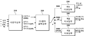
도 10은 본 발명의 다른 실시예에 따른 인코더 및 디코더의 구성을 보여주는 도면이다. 10 is a diagram illustrating a configuration of an encoder and a decoder according to another embodiment of the present invention.
도 10은 디코더의 스피커 셋업이 각기 다를 경우에 스케일러블한 코딩을 위한 구조를 나타낸다. FIG. 10 shows a structure for scalable coding when the speaker setup of the decoder is different.
인코더는 다운믹싱부(210)를 포함하고, 디코더는 디멀티플렉싱부(220)를 포함하고, 제1 디코딩부(230) 내지 제3 디코딩부(250) 중 하나 이상을 포함한다.The encoder includes the
다운믹싱부(210)는 멀티채널에 해당하는 입력신호(CH_N)을 다운믹싱함으로써, 다운믹스 신호(DMX)를 생성한다. 이 과정에서 업믹스 파라미터(UP) 및 업믹스 레지듀얼(UR) 중 하나 이상을 생성한다. 그런 다음 다운믹스 신호(DMX), 업믹스 파라미터(UP) (및 업믹스 레지듀얼(UR))를 멀티플렉싱함으로써, 하나 이상의 비트스트림을 생성하여 디코더에 전송한다.The
여기서 업믹스 파라메터(UP)는 하나 이상의 채널을 둘 이상을 채널로 업믹싱하기 위해 필요한 파라미터로서, 공간 파라메터 및 채널간 위상 차이(IPD) 등이 포함될 수 있다.Here, the upmix parameter UP is a parameter required to upmix two or more channels to one or more channels, and may include a spatial parameter and an inter-channel phase difference (IPD).
그리고 업믹스 레지듀얼(UR)은 원본 신호인 입력 신호(CH_N)과 복원된 신호와의 차이인 레지듀얼 신호에 해당하는데, 여기서 복원된 신호는 다운믹스(DMX)에 업믹스 파라미터(UP)를 적용하여 업믹싱된 신호일 수도 있고, 다운믹싱부(210)에 의해 다운믹싱되지 않은 채널이 discrete한 방식으로 인코딩된 신호일 수 있다.The upmix residual signal UR corresponds to a residual signal which is a difference between the original signal CH_N and the recovered signal. The recovered signal corresponds to an upmix parameter UP to the downmix DMX And the downmixed signal by the
디코더의 디멀티플렉싱부(220)는 하나 이상의 비트스트림으로부터 다운믹스 신호(DMX) 및 업믹스 파라미터(UP)를 추출하고 업믹스 레지듀얼(UR)를 더 추출할 수 있다. 여기서 레지듀얼 신호는 다운믹스 신호에 대한 개별 부호화 유사한 방법으로 부호화될 수 있다. 따라서, 레지듀얼 신호의 복호화는 도 8 혹은 도 9에 제시된 시스템에서는 개별 (채널) 복호화기를 통해 이뤄지는 것이 특징이다.The
디코더의 스피커 셋업 환경에 따라서, 제1 디코딩부(230) 내지 제3 디코딩부(250) 중 하나(또는 하나 이상)를 선택적으로 포함할 수 있다. 디바이스의 종류(스마트폰, 스테레오 TV, 5.1ch 홈시어터, 22.2ch 홈시어터 등)에 따라서 라우드 스피커의 셋업 환경이 다양할 수 있다. 이와 같이 다양한 환경에도 불구하고, 22.2ch 등의 멀티채널 신호를 생성하기 위한 비트스트림 및 디코더가 선택적이지 않다면, 22.2ch의 신호를 모두 복원한 후에, 스피커 재생환경에 따라서, 다시 다운믹스 해야 한다. 이러한 경우, 복원 및 다운믹스에 소요되는 연산량이 매우 높을 뿐만 아니라, 지연이 발생할 수도 있다. (Or one or more) of the
그러나 본 발명의 다른 실시예에 따르면, 각 디바이스의 셋업 환경에 따라서 제1 디코더 내지 제3 디코더 중 하나(또는 하나 이상)을 선택적으로 구비함으로써, 상기와 같은 불리함으로 해소할 수 있다.However, according to another embodiment of the present invention, the disadvantage can be solved by selectively providing one (or more) of the first decoder to the third decoder according to the setup environment of each device.
제1 디코더(230)는 다운믹스 신호(DMX)만을 디코딩하는 구성으로써, 채널 수의 증가를 동반하지 않는다. 다운믹스 신호가 모노인 경우, 모노 채널 신호를 출력하고, 만약 스테레오인 경우, 스테레오 신호를 출력하는 것이다. 스피커 채널 수가 하나나 또는 두 개인 헤드폰 구비된 장치, 스마트폰, TV 등에 적합할 수 있다.The
한편, 제2 디코더(240)는 다운믹스 신호(DMX) 및 업믹스 파라미터(UP)를 수신하고, 이를 근거로 파라메트릭 M채널(PM)을 생성한다. 제1 디코더에 비해서 채널 수가 증가하지만, 업믹스 파라미터(UP)가 총 M채널까지의 업믹스에 해당하는 파라미터만 존재하는 경우, 원본 채널 수(N)에 못미치는 M채널 수의 신호를 재생할 수 있다. 예를 들어 인코더의 입력신호인 원본 신호가 22.2ch 신호이고, M채널은 5.1ch, 7.1ch 채널 등일 수 있다.Meanwhile, the
제3 디코더(250)는 다운믹스 신호(DMX) 및 업믹스 파라미터(UP) 뿐만 아니라, 업믹스 레지듀얼(UR)까지 수신한다. 제2 디코더는 M채널의 파라메트릭 채널을 생성하는 데 비해, 제3 디코더는 이에 업믹스 레지듀얼 신호(UR)까지 추가적으로 적용함으로써, N개 채널의 복원된 신호를 출력할 수 있다.The
각 디바이스는 제1 디코더 및 제3 디코더 중 하나 이상을 선택적으로 구비하고, 비트스트림 중에서 업믹스 파라미터(UP) 및 업믹스 레지듀얼(UR)을 선택적으로 파싱함으로써, 각 스피커 셋업 환경에 맞는 신호를 바로 생성함으로써, 복잡도 및 연산량을 줄일 수 있다.
Each device selectively includes one or more of a first decoder and a third decoder and selectively parses the upmix parameter UP and the upmix residual UR in the bit stream to generate a signal suitable for each speaker setup environment The complexity and the amount of computation can be reduced by creating it directly.
(마스킹 고려한 객체 웨이브폼 부호화)(Object Waveform Coding Considering Masking)
본 발명에 따른 객체의 웨이브폼 부호화기(이하 웨이브폼(waveform) 부호화기는 채널 혹은 객체 오디오 신호를 각 채널 혹은 객체별로 독립적으로 복호화가 가능하도록 부호화하는 경우를 말하며, 파라메트릭 부호화/복호화에 상대되는 개념으로 또한 개별(discrete) 부호화/복호화라고 부르기도 한다)는 객체의 사운드 장면상의 위치를 고려하여 비트할당한다. 이는 심리음향의 BMLD (Binaural Masking Level Difference) 현상과 객체 신호 부호화의 특징을 이용한 것이다. The waveform coder of an object according to the present invention (hereinafter referred to as a waveform coder) refers to a case where a channel or an object audio signal is encoded so that it can be independently decoded for each channel or object, and a concept relative to parametric encoding / (Also referred to as discrete encoding / decoding) is bit-allocated in consideration of the position on the sound scene of the object. This is based on the binaural masking level difference (BMLD) phenomenon of psychoacoustics and the features of object signal coding.
BMLD 현상을 설명하기 위해 기존 오디오 부호화 방법에서 사용하던 MS (Mid-Side) 스테레오 부호화의 예를 가지고 설명하면 다음과 같다. 즉, 심리음향에서의 마스킹 현상은 마스킹을 발생시키는 마스커(Masker)와 마스킹이 되는 마스키(Maskee)가 공간적으로 동일한 방향에 있을 때 가능하다는 것이 BMLD이다. 스테레오 오디오 신호의 두 채널 오디오 신호간의 상관성이 매우 높고, 그 크기가 같은 경우 그 소리에 대한 상(음상)이 두 스피커 사이 중앙에 맺히게 되며, 상관성이 없는 경우 각 스피커에서 독립된 소리가 나와 그 상이 각각 스피커에 맺히게된다. 만일 상관성이 최대인 입력 신호에 대해 각 채널을 독립적으로 부호화(dual mono)할 경우 이 때 발생하는 각 채널에서의 양자화 잡음은 서로 상관성이 없으므로, 오디오 신호는 중앙에, 양자화 잡음은 그 상이 각 스피커에 따로 맺히게 될 것이다. 따라서, 마스키가 되야하는 양자화 잡음이 공간적 불일치로 인해 마스킹되지 않아, 결국 사람에게 왜곡으로 들리는 문제가 발생한다. 합차부호화는 이와 같은 문제를 해결하고자, 두 채널 신호를 더한 신호 (Mid 신호)와 뺀 신호 (Difference)를 생성한 후 이를 이용하여 심리음향 모델을 수행하고, 이를 이용하여 양자화하여, 발생한 양자화 잡음이 음상과 같은 위치에 있도록 한다. In order to explain the BMLD phenomenon, an example of MS (Mid-Side) stereo coding used in the conventional audio coding method will be described as follows. That is, the masking phenomenon in psychoacoustic is possible when the masker generating the masking and the masking masking are spatially in the same direction. The correlation between the two-channel audio signals of the stereo audio signal is very high. If the sizes are the same, the phase (sound image) of the sound is centered between the two speakers. If there is no correlation, The speaker is concealed. Since the quantization noise of each channel is not correlated with each other when the channel is dual-mono independently of the input signal having the highest correlation, the audio signal is centered, . Therefore, the quantization noise to be masked is not masked due to the spatial inconsistency, resulting in a problem that the noise is distorted to the person. In order to solve such a problem, the sum-difference coding is performed by generating a psychoacoustic model using a signal obtained by subtracting a signal (Mid signal) plus two channel signals (Difference), quantizing the result using the quantized noise, Make sure it is in the same position as the sound image.
종래의 채널 부호화의 경우 각 채널은 재생되는 스피커에 매핑되며, 해당 스피커의 위치는 고정되고 서로 떨어져 있기 때문에, 채널간의 마스킹은 고려될 수 없었다. 그러나, 각 객체를 독립적으로 부호화 하는 경우는 해당 객체들의 사운드 장면상의 위치에 따라 마스킹 여부되는지 여부가 달라질 수 있다. 따라서 타 객체에 의해 현재 부호화되는 객체의 마스킹 여부를 판단하여 그에 따라 비트를 할당하여 부호화하는 것이 바람직하다. In the conventional channel coding, each channel is mapped to a speaker to be reproduced, and since the positions of the speakers are fixed and separated from each other, masking between channels can not be considered. However, when each object is encoded independently, whether the object is masked or not may be changed according to the location on the sound scene of the object. Accordingly, it is desirable to determine whether or not the object currently encoded by another object is masked, allocate and allocate bits according to the masking.
도 11은 객체 1(1110)과 객체 2(1120)에 대한 각각의 신호와 이 신호들로부터 취득될 수 있는 마스킹 임계치와 객체 1과 객체 2를 합친 신호에 대한 마스킹 임계치(1130)를 도시한다. 객체 1과 객체 2가 적어도 청자의 위치를 기준으로 동일한 위치 혹은 BMLD의 문제가 발생하지 않을 만큼의 범위내에 위치하는 것으로 간주한다면, 청자에게 해당 신호에 의해 마스킹되는 영역은 1130과 같이 될 것이므로, 객체 1에 포함된 S2신호는 완전히 마스킹되어 들리지 않는 신호가 될 것이다. 그러므로, 객체 1을 부호화하는 과정에 있어서 객체 2에 대한 마스킹 임계치를 고려하여 부호화하는 것이 바람직하다. 마스킹 임계치는 서로 가산적으로 합쳐지는 성질이 있으므로, 결국 객체 1과 객체 2에 대한 각각의 마스킹 임계치를 더하는 방법으로 구할 수 있다. 혹은 마스킹 임계치를 계산하는 과정 자체도 연산량이 매우 높으므로 객체 1과 객체 2를 미리 합하여 생성한 신호를 이용하여 하나의 마스킹 임계치를 계산하여 객체 1과 객체 2를 각각 부호화 하는 것도 바람직하다. 도 12는 본 발명에 따른 복수 객체 신호에 대한 마스킹 임계치를 산출하는 부호화기의 일 실시예이다. FIG. 11 shows a masking threshold 1130 for each signal for
본 발명에 따른 또다른 마스킹 임계치 산출 방법은 두 개의 객체 신호의 위치가 청음각 기준으로 완전히 일치 하지 않는 경우 두 객체에 대한 마스킹 임계치를 더하는 것 대신 두 객체가 공간상에 떨어진 정도를 고려하여 마스킹 레벨을 감쇄하여 반영하는 것도 가능하다. 즉 객체 1에 대한 마스킹 임계치를 M1(f), 객체 2에 대한 마스킹 임계치를 M2(f)라고 할 때, 각 객체를 부호화화는데 사용할 최종 조인트 마스킹 임계치 M1’(f), M2’(f)는 다음과 같은 관계를 갖도록 생성된다.
Another masking threshold calculation method according to the present invention is a method of calculating masking thresholds by considering the degree of separation of two objects in space, instead of adding masking thresholds for two objects when the positions of two object signals do not completely coincide with the audible angle reference It is also possible to reflect it by attenuating it. The final joint masking thresholds M1 '(f) and M2' (f) to be used to encode each object when the masking threshold for

이때, A(f)는 두 객체간 공간상의 위치와 거리 및 두 객체의 속성 등을 통해 생성되는 감쇄팩터로써 0.0=<A(f)=<1.0 의 범위를 갖는다. In this case, A (f) is an attenuation factor generated by the position and distance of space between two objects and the properties of two objects, and has a range of 0.0 = <A (f) = <1.0.
사람의 방향에 대한 해상도는 정면을 기준으로 좌우로 갈 수록 나빠지고 뒤쪽으로 갈 때 더욱 나빠지는 특성을 갖는데, 따라서, 객체의 절대적 위치는 A(f)를 결정하는 또다른 요소로 작용할 수 있다.
The resolution of a person's direction is deteriorated as it goes from side to side with respect to the front and becomes worse when going backward. Therefore, the absolute position of an object can serve as another factor for determining A (f).
본 발명에 따른 또 다른 실시예에서는, 두 객체 가운데 하나의 객체에 대해서는 자신의 마스킹 임계치만을 이용하고, 또 다른 객체에 대해서만 상대 객체에 대한 마스킹 임계치를 가져오는 방법으로 구현할 수 있다. 이를 각각 독립객체 의존객체라고 한다. 자기 자신의 마스킹 임계치만을 이용하는 객체는 상대 객체와 무관하게 고음질 부호화 되므로, 해당 객체로부터 공간적으로 분리되는 렌더링이 수행되더라도 음질이 보존되는 장점을 가질 수 있다. 객체 1을 독립객체, 객체 2를 의존객체라고 하면, 다음과 같은 식으로 마스킹 임계치가 표현될 수 있다.
According to another embodiment of the present invention, a masking threshold value of only one of two objects is used, and a masking threshold value of a relative object is acquired only for another object. This is called an independent object dependent object. Since the object using only its own masking threshold is high-quality encoded regardless of the relative object, the sound quality can be preserved even if the object is spatially separated from the object. Assuming that

독립객체와 의존객체 여부는 각 객체에 대한 부가정보로써 복호화 및 렌더러에 전달하는 것이 바람직하다. Whether an independent object or a dependent object is the additional information for each object is preferably decoded and transmitted to the renderer.
본 발명에 따른 또 다른 실시예에서는, 두 객체가 공간상에서 일정정도 유사한 경우, 마스킹 임계치만을 합쳐서 생성하는 것이 아니라, 신호 자체를 하나의 객체로 합쳐서 처리하는 것도 가능하다.In another embodiment according to the present invention, when two objects are similar to each other in space, it is also possible to combine the signals themselves into one object, instead of merely generating the masking thresholds.
본 발명에 따른 또 다른 실시예에서는, 특히 파라미터 부호화를 수행하는 경우, 두 신호의 상관도와 두 신호의 공간 상의 위치를 고려하여, 하나의 객체로 합쳐서 처리하는 것이 바람직하다.
In another embodiment according to the present invention, in particular, when parameter coding is performed, it is preferable to combine the two signals into one object in consideration of the correlation between the two signals and the spatial position of the two signals.
(트랜스코딩 특징)(Transcoding feature)
본 발명에 따른 또 다른 실시예에서는, 커플링된 객체를 포함한 비트열을 트랜스코딩 함에 있어서, 특히 더 낮은 비트율로 트랜스 코딩 함에 있어서, 데이터 크기를 줄이기 위해 객체의 숫자를 줄여야 할 경우, 즉, 복수 객체를 하나로 다운믹스 하여 하나의 객체로 표현할 경우, 커플링된 객체에 대해 하나의 객체로 표현하는 것이 바람직하다.In another embodiment according to the present invention, in transcoding a bit string including a coupled object, particularly when transcoding at a lower bit rate, when the number of objects is reduced in order to reduce the data size, When an object is downmixed into a single object, it is preferable to represent the coupled object as a single object.
이상의 객체간 커플링을 통한 부호화를 설명함에 있어서, 설명의 편의를 위해 2개의 객체만을 커플링하는 경우만을 예로 들었으나, 2개 이상 다수의 객체에 대한 커플링도 유사한 방법으로 구현 가능하다.
In the description of the encoding through the inter-object coupling, only the case of coupling only two objects is described as an example for convenience of explanation, but coupling to two or more objects can also be implemented in a similar manner.
(유연한 렌더링 필요) (Flexible rendering required)
3D 오디오를 위해 필요한 기술 가운데 유연한 렌더링은 3D 오디오의 품질을 최상으로 끌어올리기 위해 해결해야할 중요한 과제 가운데 하나이다. 거실의 구조, 가구 배치에 따라 5.1 채널 스피커의 위치가 매우 비정형적인 것은 주지의 사실이다. 이와 같은 비정형적 위치에 스피커가 존재하더라도, 컨텐츠 제작자가 의도한 사운드 장면을 제공할 수 있도록 해야하는데, 이를 위해서는 사용자마다 제각각인 재생 환경에서의 스피커 환경을 알아야 하는 것과 함께, 규격에 따른 위치 대비 차이를 보정하기 위한 렌더링 기술이 필요하다. 즉, 전송된 비트열을 디코딩 방법에 따라 디코딩하는 것으로 코덱의 역할이 끝나는 것이 아니라, 이를 사용자의 재생 환경에 맞게 최적화 변형하는 과정에 대한 일련의 기술이 요구된다. Among the technologies required for 3D audio, flexible rendering is one of the key challenges to be solved to maximize the quality of 3D audio. It is well known that the position of the 5.1 channel speaker is very irregular depending on the structure of the living room and the arrangement of the furniture. Even if there is a speaker at such an irregular position, a content producer should be able to provide a sound scene intended by the user. In order to do this, it is necessary to know the speaker environment in the reproduction environment which is different for each user, A rendering technique is needed to compensate for this. That is, a series of techniques are required to decode the transmitted bit stream according to the decoding method, and not to end the codec role, but to optimize and transform it according to the user's reproduction environment.
도 13은 5.1채널 셋업에 대해 ITU-R 권고안에 따른 배치(회색, 1310)와 임의 위치에 배치된 경우(붉은색, 1320)를 나타낸다. 실제 거실 환경에서는 이처럼 ITU-R 권고안 대비 방향각과 거리 모두 달라지는 문제가 발생할 수 있다. (그림에 나타내지 않았지만 스피커의 높이에도 차이가 있을 수 있다.) 이와 같이 달라진 스피커 위치에서 원래의 채널 신호를 그대로 재생할 경우 이상적인 3D 사운드 장면을 제공하기 힘들다.
FIG. 13 shows a layout (gray, 1310) according to the ITU-R recommendation for a 5.1 channel setup and a case (red, 1320) arranged at an arbitrary position. In the actual living room environment, there may be a problem that the direction angle and the distance are different from the ITU-R recommendation. (Although it is not shown, there may be differences in the speaker's height.) It is difficult to provide the ideal 3D sound scene when the original channel signal is reproduced from such a different speaker position.
(플렉서블 렌더링)(Flexible rendering)
신호의 크기를 기준으로 두 스피커 사이의 음원의 방향 정보를 결정하는 Amplitude Panning이나 3차원 공간상에서 3개의 스피커를 이용하여 음원의 방향을 결정하는데 널리 사용되는 VBAP (Vector-Based Amplitude Panning)을 이용하면 객체별로 전송된 객체 신호에 대해서는 상대적으로 편리하게 플렉서블 렌더링을 구현할 수 있는 것을 알 수 있다. 채널 대신 객체 신호를 전송하는 것의 장점 중 하나이다.
Amplitude Panning, which determines the direction information of a sound source between two speakers based on the signal size, or Vector-Based Amplitude Panning (VBAP), which is widely used to determine the direction of a sound source using three speakers in a three-dimensional space It can be seen that flexible rendering can be implemented relatively conveniently for object signals transmitted on an object-by-object basis. It is one of the advantages of transmitting object signals instead of channels.
(객체 복호화와 렌더링 구조)(Object Decoding and Rendering Structure)
도 14는 본 발명에 따른 객체 비트열에 대한 복호화기와 이를 이용한 플렉서블 렌더링 시스템이 연결된 두가지 실시예의 구조(1400, 1401)를 나타낸다. 전술한 바와 같이 객체의 경우 원하는 사운드 장면에 맞춰 객체를 음원으로 위치시키기 용이한 장점이 있으며, 여기서는 믹스(Mix, 1420)부에서 믹싱행렬로 표현된 위치정보를 입력받아서 우선 채널 신호로 변경한다. 즉, 사운드 장면에 대한 위치정보를 출력 채널에 대응되는 스피커로부터의 상대적인 정보로써 표현되는 것이다. 이때, 실제 스피커의 개수와 위치가 정해진 위치에 존재하지 않는 경우 해당 위치 정보(Speaker Config)를 이용하여 다시 렌더링 하는 과정이 필요하다. 아래 기술하는 것처럼 채널 신호를 다시 다른 형태의 채널 신호로 렌더링하는 것은 객체를 최종 채널에 직접 렌더링하는 경우보다 구현하기 어렵다. FIG. 14 shows structures (1400 and 1401) of two embodiments in which a decoder for an object bit stream and a flexible rendering system using the decoder are connected to each other according to the present invention. As described above, in the case of an object, there is an advantage in that an object can be positioned as a sound source in accordance with a desired sound scene. Here, the
도 15는 본 발명에 따른 객체 비트열에 대한 복호화와 렌더링을 구현한 또 다른 실시예의 구조를 나타낸다. 도 14의 경우와 비교하면, 비트열로부터 복호화와 함께 최종 스피커 환경에 맞는 플렉서블 렌더링(1510)을 직접 구현하는 것이다. 즉, 믹싱 행렬에 바탕하여 정형의 채널로 수행하는 믹싱과 이렇게 생성된 정형 채널로부터 플렉서블 스피커로 렌더링하는 과정의 두 단계를 거치는 대신 믹싱행렬과 스피커 위치정보(1520)를 이용하여 하나의 렌더링 행렬 혹은 렌더링 파라미터를 생성하여, 이를 이용하여 객체 신호를 대상 스피커로 바로 렌더링하는 것이다.
FIG. 15 shows a structure of still another embodiment implementing decryption and rendering of an object bit stream according to the present invention. Compared with the case of FIG. 14, it is possible to directly implement the
(채널로 붙여서 플렉서블 렌더링)(Flexible rendering with channel attached)
한편, 채널 신호가 입력으로 전송된 경우, 해당 채널에 대응되는 스피커의 위치가 임의 위치로 변경된 경우는 객체 경우의 같은 패닝 기법을 이용하여 구현되기 어렵고 별도의 채널 매핑 프로세스가 필요하다. 더 문제는 이처럼 객체 신호와 채널 신호에 대해 렌더링을 위해 필요한 과정과 해결 방법이 다르기 때문에 객체 신호와 채널 신호가 동시에 전송되어 두 신호를 믹스한 형태의 사운드 장면을 연출하고자 하는 경우는 공간의 부정합에 의한 왜곡이 발생하기 쉽다. 이와 같은 문제를 해결하기 위해 본 발명에 따른 또다른 실시예에서는 객체에 대한 플렉서블 렌더링을 별도로 수행하지 않고 채널 신호에 믹스를 먼저 수행한 후 채널 신호에 대한 플렉서블 렌더링을 수행하도록 한다. HRTF를 이용한 렌더링 등도 마찬가지 방법으로 구현되는 것이 바람직하다.
On the other hand, when the channel signal is transmitted as an input, if the position of the speaker corresponding to the channel is changed to an arbitrary position, it is difficult to implement using the same panning method in the case of an object, and a separate channel mapping process is required. The problem is that the process and solution required for rendering the object signal and the channel signal are different from each other. Therefore, when the object signal and the channel signal are simultaneously transmitted and a sound scene in which the two signals are mixed is desired, Distortion is likely to occur. In order to solve such a problem, according to another embodiment of the present invention, flexible rendering of a channel signal is performed after a mix is first performed on a channel signal without separately performing flexible rendering on an object. Rendering using HRTF is preferably implemented in the same manner.
(복호화단 다운믹스: 파라미터 전송 혹은 자동생성)(Decoded downmix: parameter transmission or automatic generation)
다운믹스 렌더링의 경우, 멀티채널 컨텐츠를 그보다 적은 수의 출력 채널을 통해 재생하는 경우 지금까지는 M-N 다운믹스 매트릭스 (M은 입력채널 수, N은 출력 채널 수)로 구현하는 것이 일반적이었다. 즉, 5.1 채널 컨텐츠를 스테레오로 재생할 때, 주어진 수식에 의해 다운믹스를 수행하는 식으로 구현된다. 그런데, 이와 같은 다운믹스 구현 방법은 우선 사용자의 재생 스피커 환경이 5.1채널 뿐임에도 불구하고, 전송된 22.2채널에 해당하는 모든 비트열을 복호화해야하는 연산량의 문제가 발생한다. 휴대기기에서의 재생을 위한 스테레오 신호 생성을 위해서도 22.2채널 신호를 모두 복호화 해야한다면, 그 연산량 부담이 매우 높을 뿐 아니라 엄청난 양의 메모리 낭비(22.2채널 복호화된 오디오 신호의 저장)가 발생한다.
In the case of downmix rendering, in the case of reproducing multi-channel contents through a smaller number of output channels, up to now, it has been common to implement an MN downmix matrix (M is the number of input channels and N is the number of output channels). That is, when 5.1 channel contents are reproduced in stereo, downmix is performed by a given expression. However, such a downmix implementation method has a problem of a calculation amount of decoding all bit strings corresponding to 22.2 transmitted channels, although the user's playback speaker environment is only 5.1 channels. In order to generate a stereo signal for reproduction on a portable device, if all the 22.2 channel signals need to be decoded, the computational burden is very high, and a huge amount of memory waste (storage of 22.2 channel decoded audio signals) occurs.
(다운믹스 대안으로의 트랜스코딩)(Transcoding as an alternative to downmix)
이에 대한 대안으로 거대한 22.2채널 원본 비트열로부터 효과적인 트랜스코딩을 통해 목표 기기 혹은 목표 재생 공간에 적합한 수의 비트열로 전환하는 방법을 생각할 수 있다. 예를 들어 클라우드 서버에 저장된 22.2채널 컨텐츠라면, 클라이언트 단말로부터 재생 환경 정보를 수신하고 이에 맞게 변환하여 전송하는 시나리오가 구현가능하다.
As an alternative to this, a method of switching from a huge 22.2 channel original bit stream to a bit stream suitable for the target device or target playback space through effective transcoding can be considered. For example, if the content is 22.2 channel content stored in the cloud server, it is possible to implement a scenario in which the reproduction environment information is received from the client terminal, and converted and transmitted.
(복호화 순서 혹은 다운믹스 순서; 순서제어부)(Decryption sequence or downmix sequence; sequence control unit)
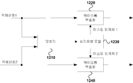
한편, 복호화기와 렌더링이 분리되어 있는 시나리오의 경우, 예를 들어 22.2채널의 오디오 신호와 함께 50개의 객체신호를 복호화하여 이를 렌더러에 전달해야하는 경우가 발생할 수 있는데, 전송되는 오디오 신호는 복호화가 완료된 높은 데이터율의 신호이므로, 복호화기와 렌더러 사이에 매우 큰 대역폭을 요구하는 문제가 있다. 따라서, 한번에 이와 같이 많은 데이터를 동시에 전송하는 것은 바람직하지 않으며, 효과적인 전송계획을 세우는 것이 바람직하다. 그리고, 이에 맞게 복호화기가 복호화 순서를 결정하여 전송하는 것이 바람직하다. 도 16은 이와 같이 복호화기와 렌더러 사이의 전송계획을 결정하여 전송하는 구조를 나타내는 블록도이다. On the other hand, in the scenario in which the decoder and the rendering are separated, for example, there may be a case where it is necessary to decode 50 object signals together with an audio signal of 22.2 channels and transmit the decoded object signals to the renderer. Since it is a data rate signal, there is a problem that a very large bandwidth is required between the decoder and the renderer. Therefore, it is not desirable to simultaneously transmit such a large amount of data at once, and it is desirable to establish an effective transmission plan. Then, it is preferable that the decoder decides the decoding order and transmits it. FIG. 16 is a block diagram showing a structure for determining and transmitting a transmission plan between the decoder and the renderer.
순서제어부(1630)는 비트열에 대한 복호화를 통해 취득한 부가정보 및 메타데이터와 렌더러(1620)로부터 재생 환경, 렌더링 정보 등을 수신하여 복호화 순서와 복호화된 신호를 렌더러(1620)에 전송하는 전송 순서 및 단위 등을 결정하여 결정된 통제 정보를 복호화기(1610)와 렌더러(1620)에 다시 전달하는 역할을 담당한다. 예를 들어 렌더러(1620)에서 특정 객체를 완전히 제거하도록 명령한 경우, 이 객체는 렌더러(1620)로의 전송이 불필요할 뿐 아니라, 복호화도 할 필요가 없다. 혹은 다른 예로 특정 객체들을 특정 채널로만 렌더링하는 상황인 경우, 해당 객체를 별도로 전송하는 대신 전송되는 해당 채널에 미리 다운믹스하여 전송하면 전송 대역이 줄어들 것이다. 또 다른 실시 예로, 사운드 장면을 공간적으로 그룹핑하여, 각 그룹별로 렌더링에 필요한 신호들을 같이 전송하면, 렌더러 내부 버퍼에서 불필요하게 대기해야하는 신호의 양을 최소화할 수 있다. 한편 렌더러(1620)에 따라 한번에 수용 가능한 데이터 크기가 다를 수 있는데 이와 같은 정보도 순서제어부(1630)에 통지하여 이에 맞게 복호화기(1610)가 복호화 타이밍 및 전송량을 결정할 수 있다. The
한편, 순서제어부(1630)에 의한 복호화 통제는 나아가서 부호화단에 전달되어, 부호화 과정까지 통제할 수 있다. 즉, 불필요한 신호를 부호화 시 제외하거나, 객체, 채널에 대한 그룹핑을 결정하는 등이 가능하다.
On the other hand, the decoding control by the
(음성 고속도로)(Voice highway)
한편, 비트열 가운데 양방향 통신에 해당하는 음성에 해당하는 객체가 포함될 수 있다. 양방향 통신은 다른 컨텐츠와 다르게 시간 지연에 매우 민감하므로, 이에 해당하는 객체 혹은 채널 신호가 수신된 경우, 이를 우선하여 렌더러에 전송해야한다. 이에 해당하는 객체 혹은 채널신호는 별도의 플래그 등으로 표시할 수 있다. 우선 전송 객체는 타 객체/채널과 다르게 같은 프레임에 들어있는 다른 객체/채널 신호와 재생 시간(presentation time)에 있어서 독립적인 특성을 갖는다.
On the other hand, an object corresponding to a voice corresponding to bidirectional communication may be included in the bit stream. Since bidirectional communication is very sensitive to time delay unlike other contents, when the corresponding object or channel signal is received, it should be transmitted to the renderer first. The corresponding object or channel signal can be indicated by a separate flag or the like. First of all, the transport object is independent of the other object / channel signals contained in the same frame and the presentation time, unlike the other object / channel.
(AV 정합 및 Phantom Center)(AV Matching and Phantom Center)
UHDTV 즉 초고해상도 TV를 고려할 때, 발생하는 새로운 문제 가운데 하나로, 흔히 Near Field라고 부르는 상황이다. 즉, 일반적인 사용자 환경(거실)의 시청 거리를 고려할 때, 재생되는 스피커로부터의 청자까지의 거리가 각 스피커 사이의 거리보다 짧아짐으로 인해, 각 스피커가 점 음원으로 동작하게 된다는 점과 넓고 큰 스크린에 의해 중앙부에 스피커가 부재하게 된 상황에서 비디오에 동기화된 소리 객체의 공간 해상도가 매우 높아야만 고품질 3D 오디오 서비스가 가능하다는 점이다. UHDTV is one of the new problems when considering ultra-high-definition TV, which is often called a near field. That is, considering the viewing distance of a general user environment (living room), the distance from the reproduced speaker to the listener is shorter than the distance between the speakers, so that each speaker operates as a point source, In the absence of a speaker at the center, the spatial resolution of the sound object synchronized to the video must be very high to enable high quality 3D audio service.
종래의 30도 정도의 시청각에서는 좌우에 배치된 스테레오 스피커가 Near Field 상황에 놓이지 않으며, 화면상의 객체의 이동 (예를 들어 왼쪽에서 오른쪽으로 이동하는 자동차)에 맞는 사운드 장면을 제공하기에 충분하다. 그러나, 시청각이 100도에 이르는 UHDTV 환경에서는 좌우 해상도뿐 아니라 화면의 상하를 구성하는 추가의 해상도가 필요하다. 예를 들어, 화면상의 2명의 등장 인물이 있을 경우, 현재의 HDTV에서는 두 명의 소리가 모두 가운데서 발화되는 것으로 들려도 현실감에 있어 큰 문제로 느껴지지 않았지만, UHDTV 크기에서는 화면과 그에 대응하는 소리의 불일치가 새로운 형태의 왜곡으로 인식될 것이다.In a conventional audio angle of about 30 degrees, stereo speakers arranged on the left and right are not in a near field situation, and are sufficient to provide a sound scene suitable for movement of an object on the screen (for example, a vehicle moving from left to right). However, in the UHDTV environment where the audiovisual angle is 100 degrees, not only the left and right resolutions but also additional resolutions constituting the top and bottom of the screen are required. For example, if there are two characters on the screen, it would not be a big problem in realistic sense even if it is said that two sounds are ignited in current HDTV. However, in UHDTV size, Will be perceived as a new form of distortion.
이에 대한 해결방안 중 하나로 22.2 채널 스피커 configuration의 형태를 들 수 있다. 도 2는 22.2채널 배치의 한 예이다. 도 2에 따르면, 전면부에 총 11개의 스피커를 배치하여 전면의 좌우 및 상하 공간 해상도를 크게 높이고 있다. 종전 3개의 스피커가 담당하던 중간층에 5개의 스피커를 배치한다. 그리고, 상위 개층 3개, 하위 계층에 3개를 추가하여 소리의 높낮이도 충분히 대응할 수 있도록 하였다. 이와 같은 배치를 이용하면 종전에 비해 전면의 공간 해상도가 높아지므로, 그만큼 비디오 신호와의 정합에 유리해질 것이다. 그런데, LCD, OLED 등의 디스플레이 소자를 이용하는 현재의 TV들에 있어, 스피커가 존재해야할 위치를 디스플레이가 차지한다는 문제가 있다. 즉, 디스플레이 자체가 소리를 제공하거나 혹은 소리를 관통하는 소자성격을 갖지 않는한 디스플레이 영역 밖에 존재하는 스피커들을 이용하여, 화면내의 각 오브젝트 위치에 정합된 소리를 제공해야하는 문제가 존재한다. 도 2에서 최소 FLc, FC, FRc에 해당하는 스피커는 디스플레이와 중복된 위치에 배치된다. One of the solutions to this problem is the configuration of 22.2 channel speaker configuration. Figure 2 is an example of a 22.2 channel arrangement. 2, a total of eleven loudspeakers are arranged on the front side to increase the left and right spatial resolution and the vertical spatial resolution of the front side. Five speakers are placed in the middle layer of the former three speakers. In addition, three upper layers and three lower layers were added so that the sound level could be sufficiently accommodated. By using such an arrangement, the spatial resolution of the front surface is higher than that of the past, which will be advantageous for matching with the video signal. However, there is a problem that, in current TVs using display devices such as LCDs and OLEDs, the display occupies a position where a speaker should be present. That is, there is a problem in that the speakers must be provided outside the display area to provide a matched sound to each object position in the screen, unless the display itself provides sound or does not have a device character that penetrates the sound. In FIG. 2, speakers corresponding to the minimums FLc, FC, and FRc are disposed at positions overlapping with the display.
도 17은 22.2 채널 시스템에서 전면 배치 스피커 가운데 디스플레이에 의해 부재한 스피커들을 그 주변 채널들을 이용하여 재생하는 개념을 설명하기 위한 개념도이다. FLc, FC, FRc 부재를 대응하기 위해 점선으로 표시한 원과 같이 추가 스피커를 디스플레이의 상하 주변부에 배치하는 경우도 고려할 수 있다. 도 17에 따르면 FLc를 생성하는데 사용할 수 있는 주변 채널은 7개가 있을 수 있다. 이 7개의 스피커를 이용하여 가상 소스를 생성하는 원리로 부재 스피커 위치에 해당하는 소리를 재생할 수 있다. 17 is a conceptual diagram for explaining a concept of reproducing speakers absent from the display among the front-mounted speakers in the 22.2 channel system using the peripheral channels. In order to accommodate the components FLc, FC and FRc, it is also conceivable to arrange additional speakers in the upper and lower peripheral portions of the display, such as circles indicated by dotted lines. According to FIG. 17, there may be seven peripheral channels that can be used to generate the FLc. By using these seven speakers, it is possible to reproduce a sound corresponding to the position of a member speaker by the principle of generating a virtual source.
주변 스피커를 이용하여 가상 소스를 생성하는 방법으로 VBAP이나 HAAS Effect (선행 효과)와 같은 기술 및 성질을 이용할 수 있다. 혹은 주파수 대역에 따라 서로 다른 패닝 기법을 적용할 수 있다. 나아가서는 HRTF를 이용한 방위각 변경 및 높이 조절 등을 고려할 수 있다. 예를들어 BtFC를 이용하여 FC를 대체할 경우, 상승 성질을 갖는 HRTF를 적용하여 FC 채널 신호를 BtFC에 더하는 방법으로 구현할 수 있다. HRTF 관찰을 통해 파악할 수 있는 성질은 소리의 높이를 조절하기 위해서는 고주파수 대역의 특정 Null의 위치(이는 사람에 따라 다름)를 제어해야한다는 것이다. 그런데, 사람에 따라 다른 Null을 일반화하여 구현하기 위해서는 고주파수 대역을 넓게 키우거나 줄이는 방법으로 높이 조절을 구현할 수 있다. 이와 같은 방법을 사용하면 대신 필터의 영향으로 신호에 왜곡이 발생하는 단점이 있다. Techniques and properties such as VBAP or HAAS Effect (pre-effect) can be used as a method of creating virtual sources using peripheral speakers. Alternatively, different panning techniques may be applied depending on the frequency band. Further, it is possible to consider changing the azimuth using the HRTF and adjusting the height. For example, when replacing FC with BtFC, it can be implemented by adding FC channel signal to BtFC by applying HRTF with ascending property. The HRTF observation is that you have to control the position of a specific Null in the high frequency band (which varies from person to person) in order to control the height of the sound. However, in order to generalize a different Null according to a person, height adjustment can be implemented by increasing or decreasing the high frequency band widely. If such a method is used, there is a disadvantage that the signal is distorted due to the influence of the filter.
본 발명에 따른 부재 스피커 위치에의 음원 배치를 위한 처리 방법은 도 18에 제시된 것과 같다. 도 18에 따르면 팬텀 스피커 위치에 대응하는 채널 신호가 입력신호로 사용되며, 입력신호는 3개의 밴드로 분할하는 서브밴드 필터부(1810)를 거친다. 스피커 어레이가 없는 방법으로 구현될 수도 있는데, 이 경우 3개 밴드 대신 2개 밴드로 구분하거나 3개 밴드로 분할한 대신 상위 2개 밴드에 대해 각기 다른 처리를 거치는 방법으로 구현될 수도 있다. 첫번째 밴드는 저주파 대역으로 상대적으로 위치에 둔감한 대신 크기가 큰 스피커를 통해 재생하는 것이 바람직하므로, 우퍼 혹은 서브우퍼를 통해 재생될 수 있는 신호이다. 이때, 선행 효과를 이용하기 위해 첫번째 밴드 신호는 시간 지연(1820)을 추가한다. 이때 시간 지연은 다른 밴드에서의 처리 과정에서 발생하는 필터의 시간 지연을 보상하기 위한 것이 아니라, 다른 밴드 신호 대비 더 늦게 재생되도록 하기 위해 즉, 선행 효과를 제공하기 위한 추가적인 시간 지연을 제공한다. The processing method for arranging the sound sources at the position of the member speaker according to the present invention is the same as that shown in Fig. Referring to FIG. 18, a channel signal corresponding to the phantom speaker position is used as an input signal, and the input signal is passed through a
두번째 밴드는 팬텀 스피커 주변의 (TV 디스플레이의 배젤 및 그 주변에 배치되는 스피커) 스피커를 통해 재생되는데 사용될 신호로써, 적어도 2개의 스피커로 분할되어 재생되며, VBAP 등의 패닝 알고리즘(1830)을 적용하기 위한 계수가 생성되어 적용된다. 따라서, 두번째 밴드 출력이 재생되는 스피커의 개수와 위치(팬텀 스피커에 대해 상대적인)를 정확히 제공해야 이를 통한 패닝효과가 향상될 수 있다. 이때 VBAP 패닝 이외에도 HRTF를 고려한 필터의 적용이나, 시간 패닝 효과를 제공하기 위해 서로 다른 위상 필터 혹은 시간 지연 필터를 적용하는 것도 가능하다. 이와 같이 밴드를 나누어 HRTF를 적용할 때 얻을 수 있는 또다른 장점은 HRTF에 의해 발생하는 신호 왜곡의 범위를 처리하는 대역내로 제한할 수 있다는 점이다. The second band is a signal to be used to be reproduced through a speaker (a speaker disposed in the bubble of the TV display and the surroundings thereof) around the phantom speaker, is divided into at least two speakers and reproduced, and a
세번째 밴드는 스피커 어레이가 존재하는 경우 이를 이용하여 재생되는 신호를 생성하기 위함이며, 적어도 3개의 스피커를 통한 음원 가상화를 위한 어레이 신호처리 기술(1840)을 적용할 수 있다. 혹은 WFS (Wave Field Synthesis)를 통해 생성되는 계수를 적용할 수 있다. 이때, 세번째 밴드와 두번째 밴드는 실제로 같은 밴드일 수도 있다.
The third band may be used to generate a signal to be reproduced using a speaker array if present, and an array
도 19는 각 밴드에서 생성된 신호를 TV 주변에 배치된 스피커와 매핑시키는 일 실시예를 나타낸다. 도 19에 따르면, 두번째 및 세번째 밴드에 대응되는 스피커의 개수 및 위치 정보는 상대적으로 정확히 정의된 위치에 있어야 하며, 그 위치 정보는 도 18의 처리 시스템에 제공되는 것이 바람직하다.
FIG. 19 shows an embodiment in which a signal generated in each band is mapped to a speaker disposed in the vicinity of the TV. According to FIG. 19, the number and position information of the speakers corresponding to the second and third bands must be located at relatively accurately defined positions, and the position information is preferably provided to the processing system of FIG.
(VOG 전체 블록도)(Whole block diagram of VOG)
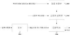
도 20은 TpC 신호가 다운믹스 되는 과정을 나타낸 개념도이다. TpC 신호 또는 머리 위쪽에 위치하는 객체 신호는 전송된 비트열의 특정 값 또는 신호의 특징을 분석하여 다운믹스 될 수 있다. 첫째로 머리 위쪽에 정지되어 있거나 방향성이 모호한 앰비언트(ambient)한 신호의 경우 다수의 채널에 동일한 다운믹스 게인을 적용하는 것이 타당하다. 이는 기존의 일반적인 매트릭스 기반 다운믹서(2010)를 사용하여 TcP 채널 또는 그 근방에 존재하는 객체신호를 다운믹스 할 수 있다. 둘째는 이동성을 가지는 사운드 장면에서의 TpC 채널 신호 또는 객체신호의 경우 앞에서 언급한 매트릭스 기반 다운믹서(2010)을 사용할 경우 컨텐츠 제공자가 의도한 동적인 사운드 장면이 보다 정적해진다. 이를 방지하기 위하여 채널 신호들을 분석하거나 객체 신호의 메타정보를 이용하여 가변적인 이득 값을 가지는 다운믹스를 수행 할 수 있다. 이를 경로 기반 다운믹서(2020)이라고 부른다. 마지막으로 마지막으로 근방의 스피커만으로 원하는 효과를 충분히 얻을 수 없는 경우 특정 N개의 스피커의 출력 신호에 사람이 높이를 지각하는 스펙트럴 단서들을 사용할 수 있다. 이를 가상 채널 생성기(2030)이라고 부른다. 다운믹서 선택부(2040)에서는 입력 비트열 정보를 이용하거나 입력 채널 신호들을 분석하여 어떤 다운믹스 방법을 사용할 지 결정된다. 이렇게 선택된 다운믹스 방법에 따라 L, M 또는 N개의 채널 신호로 출력신호가 결정되게 된다.
20 is a conceptual diagram illustrating a process in which the TpC signal is downmixed. The TpC signal or the object signal located above the head may be downmixed by analyzing a characteristic value or a specific value of the transmitted bit stream. First, it is reasonable to apply the same downmix gain to multiple channels in case of an ambient signal that is stationary above the head or ambiguous. This can downmix the object signals existing in the vicinity of the TcP channel using the conventional general matrix-based
(다운믹스 결정부)(Downmix determination unit)
도 21는 다운믹서 선택부(2040)의 순서도이다. 먼저 입력 비트열을 파싱하여 컨텐츠 제공자가 설정한 모드가 있는지를 체크한다. 설정된 모드가 있는 경우 해당 모드의 설정된 파라미터를 이용하여 다운믹스를 수행한다. 컨텐츠 제공자가 설정한 모드가 없는 경우 현재 사용자의 스피커 배치를 분석한다. 이는 스피커 배치가 매우 비정형인경우 앞에서 언급하였듯이 근방 채널의 이득값을 조절하는 것 만으로 다운믹스를 할 경우 컨텐츠 제공자가 의도한 사운드 장면을 충분히 재생할 수 없기 때문이다. 이를 극복하기 위해서는 사람이 높은 고도의 음상을 인지하는 여러가지 단서들을 이용하여만 한다. 21 is a flowchart of the down mixer selection unit 2040. FIG. First, the input bit string is parsed to check whether the mode set by the content provider exists. If there is a set mode, downmix is performed using the set parameters of the corresponding mode. If there is no mode set by the content provider, the speaker arrangement of the current user is analyzed. This is because, as described above, when the speaker arrangement is very irregular, it is impossible to sufficiently reproduce the sound scenes intended by the content provider when the down mix is performed merely by adjusting the gain value of the nearby channel. In order to overcome this, one only uses various clues that a person perceives a high-level sound image.
스피커 배치를 분석하는 실시 예로써 도2의 상위 레이어의 스피커들의 위치 벡터들과 재생단에서의 상위 레이어 스피커 위치 벡터들의 거리합으로 분석할 수 있다. 도2의 상위 레이어의 i번째 스피커의 위치 벡터를 Vi, 재생단에서의 i번째 스피커의 위치 벡터를 Vi' 라고 하자. 또한 스피커의 위치적 중요도에 따라 가중치를 wi라고 하면 스피커 위치 에러 Espk 는 수학식 3으로 정의될 수 있다.
As an embodiment of analyzing the speaker arrangement, it can be analyzed as the sum of the distance vectors of the position vector of the upper layer speakers of FIG. 2 and the upper layer speaker position vectors of the reproduction end. Let Vi be the position vector of the i-th speaker in the upper layer of FIG. 2, and Vi 'be the position vector of the i-th speaker at the playback end. If the weight is weighted according to the positional importance of the speaker, the speaker position error Espk can be defined by Equation (3).

사용자의 스피커 배치가 매우 비 정형적인 경우 스피커 위치 에러 Espk는 큰 값을 갖게 된다. 따라서 스피커 위치 에러 Espk가 일정 임계값을 이상 또는 초과하는 경우 이는 가상 채널 생성기를 선택한다. 스피커 위치 에러가 일정 임계값보다 미만 또는 이하인 경우 매트릭스 기반 다운믹서 또는 경로 기반 다운믹서를 사용하게 된다. 다운믹스 하려는 음원이 채널 신호인 경우 채널신호의 추정된 음상 크기의 폭에 따라 다운믹스 방법이 선택 될 수 있다. 이는 뒤에서 언급할 사람의 정위 퍼짐(localization blur)이 정중면에 비하여 굉장히 크기 때문에, 음상의 폭(apparent source width)이 넓을 경우 정교한 음상 정위 방법이 불필요하기 때문이다. 여러 채널의 음상의 폭을 측정하는 실시 예로써 양 이 신호의 상호 상관도(interaural cross correlation)을 이용하여 측정방법이 한 예가 된다. 그러나 이는 매우 복잡한 연산을 필요로하므로 각 채널간의 상호상관도는 양 이 신호의 상호상관도와 비례하다고 가정하면 TpC 채널 신호와 각 채널간의 상호상관도의 총 합를 이용하여 상대적으로 적은 연산량으로 음상의 폭을 추정할 수 있다. TpC 채널 신호를 , 주변 채널 신호를 이라고 하면, TpC 채널 신호와 주변 채널 신호간의 상호 상관도의 총 합 C를 추정하는 방법은 수학식 4으로 정의 될 수 있다.
If the speaker layout of the user is very irregular, the speaker position error Espk will have a large value. Therefore, if the speaker position error Espk exceeds or exceeds a certain threshold value, it selects a virtual channel generator. When the speaker position error is less than or equal to a certain threshold value, a matrix-based downmixer or a path-based downmixer is used. If the sound source to be downmixed is a channel signal, the downmix method may be selected according to the width of the estimated sound image size of the channel signal. This is because the localization blur of the person mentioned later is very large compared to that of the mid-plane, so that a sophisticated sound localization method is unnecessary when the apparent source width is wide. As an example of measuring the width of the sound image of several channels, an example of the measurement method using the interaural cross correlation of the signals is described. However, since it requires a very complicated operation, assuming that the amount of cross-correlation between the channels is proportional to the cross-correlation of the signals, the total sum of the cross correlation between the TpC channel signal and each channel is used, Can be estimated. A method of estimating the total sum C of cross-correlations between the TpC channel signal and the peripheral channel signal can be defined by Equation (4).
TpC 채널 신호와 주변 채널 신호간의 상호 상관도의 총 합 C가 일정 임계값을 초과 또는 이상인 경우 음상의 폭이 기준보다 넓기 때문에 매트릭스 기반 다운믹서를 사용하고, 그렇지 않은 경우 음상의 폭이 기준보다 좁은 것이므로 보다 정교한 경로 기반 다운믹서를 이용한다. If the total sum C of the cross correlation between the TpC channel signal and the surrounding channel signal exceeds or exceeds a certain threshold value, the matrix-based downmixer is used because the width of the sound image is wider than the reference value. Otherwise, , It uses a more sophisticated path-based downmixer.
반면 객체 신호의 경우 객체신호의 위치의 변화에 따라 다운믹스 방법을 선택할 수 있다. 객체신호의 위치정보는 입력 비트스트림을 파싱하여 얻을 수 있는 메타정보에 포함되어 있다. 객체신호의 위치의 변화량을 측정하는 실시 예로서 N개의 프레임동안 객체신호 위치의 통계적인 특성인 분산이나 표준편차를 이용할 수 있다. 측정된 객체신호 위치의 변화량이 일정 임계값 초과 혹은 이상인 경우 해당 객체는 위치의 변화가 크므로 보다 정교한 경로 기반 다운믹스 방법을 선택한다. 반면 그렇지 않은 경우 해당 객체신호는 정적인 음원으로 간주되므로 앞에서 언급한 사람의 정위 퍼짐에 의하여 적은 연산량임에도 효과적으로 다운믹스 할 수 있는 매트릭스 기반 다운믹서를 선택한다.
On the other hand, in case of the object signal, the downmix method can be selected according to the change of the position of the object signal. The position information of the object signal is included in meta information obtained by parsing the input bit stream. As an example of measuring the amount of change of the position of the object signal, it is possible to use a variance or a standard deviation which is a statistical characteristic of an object signal position during N frames. When the variation of the measured object signal position exceeds or exceeds a predetermined threshold value, the object changes its position greatly, so a more sophisticated path based downmixing method is selected. Otherwise, the object signal is regarded as a static sound source. Therefore, the matrix-based down mixer can be effectively downmixed even by a small amount of computation by the above-mentioned spreading of the person's station.
(정적인 음원 다운믹서 / 매트릭스 기반 다운믹서)(Static source downmixer / matrix-based downmixer)
여러 심리 음향적인 실험에 따르면 정중면(median plane)에서의 음상 정위는 수평면(horizontal plane)에서의 음상 정위와는 굉장히 다른 양상을 가진다. 이러한 음상 정위의 부정확도를 측정하는 수치로는 정위 퍼짐(localization blur)으로서 이는 특정 위치에서 음상의 위치가 구분이 가지 않는 범위를 각도로 나타낸 것이다. 앞에서 언급한 실험들에 따르면 음성신호의 경우 9도에서 17도에 해당하는 부정확도를 가진다. 그러나 수평면에서 음성신호의 경우 0.9도에서 1.5도를 갖는 것을 고려하면 정중면에서의 음상 정위는 매우 낮은 정확도를 가진다는 것을 알 수 있다. 높은 고도를 가지는 음상의 경우 사람이 인지할 수 있는 정확도가 낮기 때문에 정교한 정위 방법 보다는 매트릭스를 이용한 다운믹스가 효과적이다. 따라서 위치가 크게 변하지 않는 음상의 경우 대칭적으로 스피커가 분포 되어있는 Top채널들에 동등한 이득값을 분배함으로써 효과적으로 부재중인 TpC채널을 복수 개의 채널로 업믹스 할 수 있다. According to various psychoacoustic experiments, the sound phase orientation in the median plane is very different from the sound phase orientation in the horizontal plane. A numerical value for measuring the inaccuracy of the sound localization is a localization blur, which is an angle in which the position of the sound image is not distinguished at a specific position. According to the above-mentioned experiments, the speech signal has an inaccuracy of 9 to 17 degrees. However, it can be seen that the sound localization on the mid-plane has a very low accuracy, considering that the audio signal on the horizontal plane has 0.9 to 1.5 degrees. In the case of high-altitude images, the downmix using the matrix is more effective than the sophisticated method of localization because the human perception is low. Therefore, in the case of a sound image in which the position is not largely changed, it is possible to effectively upmix the TpC channel of the absence to a plurality of channels by distributing the equivalent gain value to the top channels in which the speakers are symmetrically distributed.
재생단의 채널 환경이 도 2의 구성에서 TpC채널을 제외하고 Top 레이어는 동일하다고 가정하면 Top 레이어에 분배되는 채널 이득값은 동일한 값을 갖는다. 그러나 재생단에서 도2와 같이 정형적인 채널 환경을 갖는 것이 어려운 것은 주지의 사실이다. 비정형한 채널 환경에서 앞에서 언급한 모든 채널에 일정 이득값을 배분하는 것은 음상이 컨텐츠가 의도한 위치와 이루는 각도가 정위 퍼짐 수치보다 커질 수 있다. 이는 사용자로 하여금 잘못된 음상을 인지하게 한다. 이를 방지하기 위하여 비정형한 채널 환경의 경우 이를 보상해주는 과정이 필요하다.In the channel environment of the playback end, assuming that the top layer is the same except for the TpC channel in the configuration of FIG. 2, the channel gain values distributed to the top layer have the same value. However, it is well known that it is difficult to have a typical channel environment as shown in FIG. 2 at the playback end. In an unsteady channel environment, distributing a constant gain value to all of the channels mentioned above may result in an angle between the sound image and the intended position of the content to be greater than the sagittal spread value. This allows the user to perceive a false image. In order to prevent this, it is necessary to compensate the unregulated channel environment.
Top 레이어에 위치하는 채널의 경우 청자의 위치에서는 평면파로 도달한다고 가정할 수 있기 때문에 일정한 이득값을 설정하는 기존의 다운믹스 방법은 주변 채널을 이용하여 TpC 채널에서 발생하는 평면파를 재현한다고 설명할 수 있다. Top 레이어를 포함하는 평면상에서 스피커들의 위치를 꼭지점으로 하는 다각형의 무게중심이 TpC채널의 위치와 같은 것과 같다. 따라서 비정형적인 채널 환경의 경우 각 채널의 이득값은 이득값이 가중치로 부여된 각 채널의 Top 레이어를 포함하는 평면 상에서의 2차원 위치벡터들의 무게중심백터가 TpC채널 위치의 위치벡터와 같다는 수식으로 얻어질 수 있다.In the case of the channel located at the top layer, since it can be assumed that a plane wave arrives at the position of the celadon, a conventional downmix method of setting a constant gain value can be described as reproducing a plane wave generated in a TpC channel have. The center of gravity of the polygon whose vertices are the positions of the speakers on the plane containing the Top layer is the same as the position of the TpC channel. Therefore, in the case of an irregular channel environment, the gain value of each channel is expressed by the equation that the center-of-gravity vector of the two-dimensional position vectors on the plane including the top layer of each channel to which the gain value is given is equal to the position vector of the TpC channel position Can be obtained.
그러나 이러한 수식적인 접근은 많은 연산량을 필요로 하며, 이후에 설명될 간략화된 방법에 비하여 성능 차이가 크지 않다. 간략화된 방법은 다음과 같다. 먼저 TpC 채널을 중심으로 N개의 영역을 등각도로 나눈다. 등각도로 나눈 영역에는 동일한 이득값을 부여하고, 만일 영역 내에 2개 이상의 스피커가 위치할 경우 각 게인의 제곱의 합이 상기 언급된 이득값과 같아지도록 설정한다. 이것의 실시 예로써 도 22와 같은 스피커 배치를 갖고, 4개의 영역을 TpC채널(2220)을 중심으로 90도의 등각도로 나누었을 때를 가정하자. 각 영역에는 크기가 같으면서 제곱의 합이 1이 되도록 하는 이득값을 부여한다. 이 경우 4개의 영역이므로 각 영역의 이득값은 0.5이다. 한 영역 상에 2개 이상의 스피커가 있는 경우 이 또한 제곱의 합이 영역의 이득값과 같아지도록 이득값을 설정한다. 따라서 오른쪽 하단 영역(2240)에 존재하는 2개의 스피커 출력의 이득값은 0.3536이다. 마지막으로 탑 레이어를 포함하는 평면 밖에 위치하는 스피커(2230)의 경우 먼저 탑 레이어를 포함하는 평면에 프로젝션 시켰을 때의 이득값을 먼저 구하고, 평면과 스피커의 거리 차이를 이득값과 딜레이를 이용하여 보상한다.
However, such a mathematical approach requires a large amount of computation, and the performance difference is not large compared with the simplified method described later. The simplified method is as follows. First, we divide the N regions around the TpC channel by a constant angle. The same gain value is given to the area divided by the equal angle, and if two or more speakers are located in the area, the sum of the squares of the gains is set to be equal to the above-mentioned gain value. Assume that this embodiment has a speaker arrangement as shown in FIG. 22 and divides the four regions by an equilateral angle of 90 degrees around the
도 23는 매트릭스 기반 다운믹서(2010)의 개념도이다. 먼저 파서(2310)를 이용하여 입력 비트열을 컨텐츠 제공자가 제공한 모드 비트와 채널신호 또는 객체신호를 분리한다. 모드 비트가 설정 되어있는 경우 스피커 결정부(2320)는 해당 스피커 그룹을 선택하고, 모드 비트가 설정되어 있지 않은 경우의 경우 현재 사용자가 사용하는 스피커 위치 정보를 이용하여 가장 최단 거리가 최소인 스피커 그룹을 선택한다. 게인 및 딜레이를 보상부(2330)에서 설정된 스피커 그룹과 실제 사용자의 스피커 배치 사이의 거리가 다른 것을 보상하기 위하여 각 스피커의 게인과 딜레이를 보상한다. 마지막으로 다운믹스 매트릭스 생성부(2340)에서 게인 및 딜레이 보상부(2330)에서 출력되는 게인 및 딜레이를 적용하여 파서에서 출력되는 채널 또는 객체신호를 다른 채널들로 다운믹스한다.
FIG. 23 is a conceptual diagram of a matrix-based
(동적인 음원 다운믹서 / 경로 기반 다운믹서)(Dynamic source downmixer / path-based downmixer)
도 24는 동적인 음원 다운믹서(2020)의 개념도이다. 먼저 파서(2410)은 입력 비트열을 파싱하여 TcP 채널 신호의 경우 복수의 채널 신호를, 객체 신호인 경우 메타정보를 경로 추정부(2420)에 전달한다. 경로 추정부(2420)에서는 복수의 채널 신호의 경우 채널간의 상관도를 추정하여 상관도가 높은 채널들의 변화를 경로로 추정한다. 반면 메타 정보의 경우 메타 정보의 변화를 경로로 추정한다. 스피커 선택부(2430)는 경로 추정부(2420)에서 추정한 경로를 이용하여 추정한 경로에서 일정 거리 이하의 스피커들을 선택한다. 이렇게 선택된 스피커들의 위치정보는 다운믹서(2440)에 전해져 해당 스피커에 맞게 다운믹스 된다. 상기 다운믹스 방법의 한 예로써 벡터 기반 진폭 패닝 기법(Vector base amplitude panning, VBAP)가 한 예가 된다.
24 is a conceptual diagram of a dynamic sound source down
(Detent effect)(Detent effect)
특정 경로를 따라 연속적으로 이동하는 음원의 경우 VBAP와 같은 진폭 패닝 방법을 이용하여 정위시키면 디텐트 효과(detent effect)가 발생한다. 디텐트 효과란 진폭 패닝 방법을 이용하여 스피커 사이에 음상을 정위시킬 때 이 음상이 정확한 위치에 맺히지 못하고 스피커 쪽으로 당겨지는 현상을 의미힌다. 이러한 현상 때문에 음상이 스피커 사이에서 연속적으로 움직일 때 이것이 연속적으로 움직이는 것이 아니라 불연속적으로 음상이 이동하게 된다. In case of a sound source moving continuously along a specific path, a detent effect occurs when the amplitude is panned by using an amplitude panning method such as VBAP. The detent effect is a phenomenon in which when the sound image is positioned between speakers using the amplitude panning method, the sound image can not be accurately positioned and pulled toward the speaker. Because of this phenomenon, when the sound image moves continuously between the speakers, it does not move continuously but the sound image moves discontinuously.
도 25는 이를 도식적으로 나타낸 도면이다. 의도된 음상(2510)이 시간에 따라 화살표 방향으로 이동한다면, 일반적인 진폭 패닝 방법을 이용하여 음상을 정위시키는 경우 정위된 음상(2520)처럼 이동하게 된다. 디텐트 효과에 의하여 스피커 방향으로 음상이 당겨져 크게 이동하지 않다가 음상의 방위각이 일정 임계값을 초과하는 경우 도 9와 같이 이동하게 된다. 이러한 문제는 음상을 일정 시간동안 위치시키는 경우에는 단지 음상 정위 오차로 조금 다른 위치에 음상이 맺히고 이는 사용자로 하여금 큰 왜곡으로 느껴지지 않는다. 그러나 디텐트 효과에 의하여 음상이 연속적으로 이동해야되는 환경에서 갑자기 불연속적으로 이동하게 된다면 이는 사용자로 하여금 큰 왜곡으로 인지하게 된다.Fig. 25 is a diagram schematically showing this. If the intended sound image 2510 moves in the direction of the arrow with time, the sound image 2520 is moved as the sound image 2520 when the sound image is positioned using the general amplitude panning method. When the sound field is pulled in the direction of the speaker due to the detent effect and the sound field is not moved largely, if the azimuth angle of the sound field exceeds a predetermined threshold value, it moves as shown in FIG. This problem is that when the image is positioned for a certain period of time, the image is formed only at a slightly different position due to the error in the image localization, and the user does not feel a large distortion. However, if the detent effect suddenly moves discontinuously in an environment in which the image must be continuously moved, the user is perceived as a large distortion.
이를 해결하기 위하여 연속적으로 이동하는 음원을 검출하고, 이에 따라 옳바른 보상을 해 줘야 한다. 가장 간단한 방법으로는 패닝게인에 가중 함수를 적용하여 덜 당겨지던 음원을 더 당겨지도록 하는 방법이 있다. 도 26은 가중 함수의 일 예로서 입력이 -1에서 1로 변할 때 특정 시그모이드 함수의 출력을 보여준다. 값이 0에 가까워질수록 값의 변화량이 커지는 것을 확인할 수 있다. 따라서 음상이 스피커에 멀어지면 멀어질수록 패닝게인의 값의 변화가 켜지기 때문에 기존의 음상이 덜 당겨지는 것을 효과적으로 보상할 수 있다. 앞의 시그모이드 함수는 일 예이며, 이러한 함수는 값이 0 또는 음상 스피커 사이의 거리가 같은 지점에 다가오면 다가갈수록 값의 변화를 크게 만드는 모든 함수가 포함될 수 있다. 더불어 이러한 디텐트 효과는 사람마다 다른 정도를 가진다. 따라서 사람의 생리학적인 특징, 실시 예로서 머리의 크기, 몸의 크기, 키, 몸무게, 외이의 모양 등의 정보를 이용하여 상기 가중함수의 변화량 등을 모델링하여 적용할 수 있다.
To solve this problem, it is necessary to detect continuously moving sound sources and compensate accordingly. The simplest way is to apply a weighting function to the panning gain so that the lesser pulled source is pulled. 26 shows an output of a particular sigmoid function when the input changes from -1 to 1 as an example of a weight function. As the value approaches 0, it can be seen that the amount of change in value increases. Therefore, as the sound image moves away from the speaker, the change in the value of the panning gain is turned on as it goes away, so that it is possible to effectively compensate for the less drawing of the conventional sound image. The above sigmoid function is an example, and these functions can include all functions that make the value change larger as the value approaches 0 or the distance between the sound image and the speaker becomes the same. In addition, the detent effect is different for each person. Therefore, it is possible to model and apply a change amount of the weighting function using information on a physiological characteristic of a person, an example of a size of a head, a size of a body, a height, a weight,
도 28은 본 발명의 일 실시예에 따른 오디오 신호 처리 장치가 구현된 제품들의 관계를 보여주는 도면이다. 우선 도 28을 참조하면, 유무선 통신부(310)는 유무선 통신 방식을 통해서 비트스트림을 수신한다. 구체적으로 유무선 통신부(310)는 유선통신부(310A), 적외선통신부(310B), 블루투스부(310C), 무선랜통신부(310D) 중 하나 이상을 포함할 수 있다.FIG. 28 is a diagram showing a relationship among products in which an audio signal processing apparatus according to an embodiment of the present invention is implemented. FIG. 28, the wired /
사용자 인증부는(320)는 사용자 정보를 입력 받아서 사용자 인증을 수행하는 것으로서 지문인식부(320A), 홍채인식부(320B), 얼굴인식부(320C), 및 음성인식부(320D) 중 하나 이상을 포함할 수 있는데, 각각 지문, 홍채정보, 얼굴 윤곽 정보, 음성 정보를 입력받아서, 사용자 정보로 변환하고, 사용자 정보 및 기존 등록되어 있는 사용자 데이터와의 일치여부를 판단하여 사용자 인증을 수행할 수 있다. The user authentication unit 320 performs user authentication by receiving the user information and performs at least one of the fingerprint recognition unit 320A, the iris recognition unit 320B, the face recognition unit 320C, and the voice recognition unit 320D The fingerprint, iris information, face contour information, and voice information may be input and converted into user information, and user authentication may be performed by determining whether the user information and the previously registered user data match each other .
입력부(330)는 사용자가 여러 종류의 명령을 입력하기 위한 입력장치로서, 키패드부(330A), 터치패드부(330B), 리모컨부(330C) 중 하나 이상을 포함할 수 있지만, 본 발명은 이에 한정되지 아니한다. The
신호 코딩 유닛(340)는 유무선 통신부(310)를 통해 수신된 오디오 신호 및/또는 비디오 신호에 대해서 인코딩 또는 디코딩을 수행하고, 시간 도메인의 오디오 신호를 출력한다. 오디오 신호 처리 장치(345)를 포함하는데, 이는 앞서 설명한 본 발명의 실시예(즉, 일 실시예에 따른 디코더(600) 및 다른 실시예에 따른 인코더 및 디코더(1400))에 해당하는 것으로서, 이와 같이 오디오 처리 장치(345) 및 이를 포함한 신호 코딩 유닛은 하나 이상의 프로세서에 의해 구현될 수 있다.The
제어부(350)는 입력장치들로부터 입력 신호를 수신하고, 신호 디코딩부(340)와 출력부(360)의 모든 프로세스를 제어한다. 출력부(360)는 신호 디코딩부(340)에 의해 생성된 출력 신호 등이 출력되는 구성요소로서, 스피커부(360A) 및 디스플레이부(360B)를 포함할 수 있다. 출력 신호가 오디오 신호일 때 출력 신호는 스피커로 출력되고, 비디오 신호일 때 출력 신호는 디스플레이를 통해 출력된다.The
본 발명에 따른 오디오 신호 처리 방법은 컴퓨터에서 실행되기 위한 프로그램으로 제작되어 컴퓨터가 읽을 수 있는 기록 매체에 저장될 수 있으며, 본 발명에 따른 데이터 구조를 가지는 멀티미디어 데이터도 컴퓨터가 읽을 수 있는 기록 매체에 저장될 수 있다. 상기 컴퓨터가 읽을 수 있는 기록 매체는 컴퓨터 시스템에 의하여 읽혀질 수 있는 데이터가 저장되는 모든 종류의 저장 장치를 포함한다. 컴퓨터가 읽을 수 있는 기록 매체의 예로는 ROM, RAM, CD-ROM, 자기 테이프, 플로피디스크, 광 데이터 저장장치 등이 있으며, 또한 캐리어 웨이브(예를 들어 인터넷을 통한 전송)의 형태로 구현되는 것도 포함한다. 또한, 상기 인코딩 방법에 의해 생성된 비트스트림은 컴퓨터가 읽을 수 있는 기록 매체에 저장되거나, 유/무선 통신망을 이용해 전송될 수 있다.The audio signal processing method according to the present invention may be implemented as a program to be executed by a computer and stored in a computer-readable recording medium. The multimedia data having the data structure according to the present invention may also be recorded on a computer- Lt; / RTI > The computer-readable recording medium includes all kinds of storage devices in which data that can be read by a computer system is stored. Examples of the computer-readable recording medium include a ROM, a RAM, a CD-ROM, a magnetic tape, a floppy disk, an optical data storage device, and the like, and may be implemented in the form of a carrier wave (for example, transmission via the Internet) . In addition, the bit stream generated by the encoding method may be stored in a computer-readable recording medium or transmitted using a wired / wireless communication network.
이상과 같이, 본 발명은 비록 한정된 실시예와 도면에 의해 설명되었으나, 본 발명은 이것에 의해 한정되지 않으며 본 발명이 속하는 기술분야에서 통상의 지식을 가진 자에 의해 본 발명의 기술사상과 아래에 기재될 특허청구범위의 균등범위 내에서 다양한 수정 및 변형이 가능함은 물론이다.
While the present invention has been particularly shown and described with reference to exemplary embodiments thereof, it is to be understood that the invention is not limited to the disclosed exemplary embodiments. It will be understood that various modifications and changes may be made without departing from the scope of the appended claims.
210 : 상위 레이어
220 : 중간 레이어
230 : 바닥 레이어
240 : LFE 채널
310 : 유무선 통신 장치
310A : 유선 통신 장치
310B : 적외선 장치
310C : 블루투스 장치
310D : 무선 LAN 장치
320 : 사용자 인증 장치
320A : 지문 인식
320B : 홍채 인식 장치
320C : 안면 인식 장치
320D : 음성 인식 장치
330 : 입력 장치
330A : 키패드
330B : 터치패드
330C : 원격 조정 장치
340 : 신호 부호화 장치
345 : 오디오 신호처리 장치
350 : 제어 장치
360 : 출력 장치
360A : 스피커
360B : 디스플레이
410 : 제 1 객체 신호 그룹
420 : 제 2 객체 신호 그룹
430 : 청자
520 : 다운 믹서 & 파라미터 부호화기1
550 : 객체그룹핑부
560 : 웨이브폼 부호화기
620 : 웨이브폼 복호화기
630 : 업믹서 & 파라미터 복호화기1
670 : 객체디그룹핑부
860 : 3DA 복호화부
870 : 3DA 렌더링부(870)
1110 : 객체1의 마스킹 임계 곡선
1120 : 객체2의 마스킹 임계 곡선
1130 : 객체3의 마스킹 임계 곡선
1230 : 심리 음향 모델
1310 : 5.1채널 라우드 스피커가 ITU-R 권고안에 따른 배치
1320 : 5.1채널 라우드 스피커가 임의 위치에 배치된 경우
1610 : 3차원 오디오 복호화기
1620 : 3차원 오디오 렌더러
1630 : 순서제어부
1810 : 서브밴드 필터부
1820 : 시간 지연 필터부
1830 : 패닝 알고리즘
1840 : 스피커 어레이 제어부
2010 : 매트릭스 기반 다운믹서
2020 : 경로 기반 다운믹서
2030 : 가상 채널 생성기
2040 : 다운 믹서 선택부
2310 : 파서
2320 : 스피커 결정부
2330 : 게인 및 딜레이 보상부
2340 : 다운믹스 매트릭스 생성부
2410 : 파서
2420 : 경로 추정부
2430 : 스피커 선택부
2440 : 다운믹서
2510 : 파서
2520 : 파라미터 추출부
2530 : 가상 채널 기반 다운믹서
210: Upper layer
220: middle layer
230: bottom layer
240: LFE channel
310: wired / wireless communication device
310A: Wired communication device
310B: Infrared device
310C: Bluetooth device
310D: Wireless LAN device
320: User authentication device
320A: Fingerprint Recognition
320B: iris recognition device
320C: Facial recognition system
320D: Speech Recognition Device
330: input device
330A: Keypad
330B: Touchpad
330C: Remote control unit
340: Signal encoding device
345: audio signal processing device
350: Control device
360: Output device
360A: Speaker
360B: Display
410: first object signal group
420: second object signal group
430: Celadon
520: Downmixer &
550: Object grouping unit
560: Waveform coder
620: Waveform Decoder
630: Upmixer &
670: Object D grouping unit
860: 3DA decoding unit
870:
1110: Masking threshold curve of
1120: masking threshold curve of
1130: masking threshold curve of
1230: Psychoacoustic model
1310: 5.1 channel loudspeaker placed according to ITU-R Recommendation
1320: 5.1 channel loudspeaker is in any position
1610: 3D audio decoder
1620: 3D Audio Renderer
1630:
1810: Subband filter section
1820: Time delay filter unit
1830: Panning Algorithm
1840: speaker array control unit
2010: Matrix based down mixer
2020: Path-based downmixer
2030: Virtual Channel Generator
2040: Downmixer selection unit
2310: Parser
2320: Speaker determination section
2330: gain and delay compensator
2340: Downmix matrix generating unit
2410: Parser
2420:
2430: speaker selection unit
2440: Downmixer
2510: Parser
2520:
2530: Virtual channel-based downmixer
Claims (4)
객체 신호와 객체 위치 정보가 포함된 비트열을 수신하는 단계;
상기 수신된 비트열을 이용하여 상기 객체 신호와 상기 객체 위치 정보를 복호화하는 단계;
과거 객체 위치 정보를 저장 매체에서 수신하는 단계;
상기 수신된 과거 객체 위치 정보와 상기 복호화된 객체 위치 정보를 이용하여 객체 이동 경로를 생성하는 단계;
상기 생성된 객체 이동 경로를 이용하여 시간에 따른 가변적 이득값을 생성하는 단계;
상기 생성된 가변적 이득값 및 가중 함수를 이용하여 수정된 가변적 이득값을 생성하는 단계;
상기 수정된 가변적 이득값을 이용하여 상기 복호화된 객체 신호로부터 채널 신호를 생성하는 단계를 포함하는 오디오 신호처리 방법.
As an audio signal processing method,
Receiving a bit string including an object signal and object position information;
Decoding the object signal and the object position information using the received bit stream;
Receiving past object position information on a storage medium;
Generating an object movement path using the received past object position information and the decoded object position information;
Generating a variable gain value according to time using the generated object movement path;
Generating a modified variable gain value using the generated variable gain value and the weighting function;
And generating a channel signal from the decoded object signal using the modified variable gain value.
상기 가중 함수는 사용자의 생리학적인 특징에 기초하여 변화하는 것을 특징으로 하는 오디오 신호처리 방법.
The method of claim 1,
Wherein the weighting function changes based on a physiological characteristic of the user.
상기 생리학적 특징은 화상이나 영상을 이용하여 추출되는 것을 특징으로 하는 오디오 신호처리 방법.
3. The method of claim 2,
Wherein the physiological characteristic is extracted using an image or an image.
상기 생리학적 특징은 사용자의 머리, 몸통의 크기 및 외이의 모양 에 대한 정보 중 적어도 하나를 포함하는 것을 특징으로 하는 오디오 신호처리 방법
3. The method of claim 2,
Wherein the physiological characteristic includes at least one of information on a shape of a head, a body of a user, and a shape of an external auditory canal of a user
Priority Applications (3)
| Application Number | Priority Date | Filing Date | Title |
|---|---|---|---|
| KR1020130047056A KR20140128564A (en) | 2013-04-27 | 2013-04-27 | Audio system and method for sound localization |
| US14/787,065 US20160104491A1 (en) | 2013-04-27 | 2014-04-24 | Audio signal processing method for sound image localization |
| PCT/KR2014/003576 WO2014175669A1 (en) | 2013-04-27 | 2014-04-24 | Audio signal processing method for sound image localization |
Applications Claiming Priority (1)
| Application Number | Priority Date | Filing Date | Title |
|---|---|---|---|
| KR1020130047056A KR20140128564A (en) | 2013-04-27 | 2013-04-27 | Audio system and method for sound localization |
Publications (1)
| Publication Number | Publication Date |
|---|---|
| KR20140128564A true KR20140128564A (en) | 2014-11-06 |
Family
ID=51792143
Family Applications (1)
| Application Number | Title | Priority Date | Filing Date |
|---|---|---|---|
| KR1020130047056A KR20140128564A (en) | 2013-04-27 | 2013-04-27 | Audio system and method for sound localization |
Country Status (3)
| Country | Link |
|---|---|
| US (1) | US20160104491A1 (en) |
| KR (1) | KR20140128564A (en) |
| WO (1) | WO2014175669A1 (en) |
Cited By (1)
| Publication number | Priority date | Publication date | Assignee | Title |
|---|---|---|---|---|
| WO2018101600A1 (en) * | 2016-11-29 | 2018-06-07 | Samsung Electronics Co., Ltd. | Electronic apparatus and control method thereof |
Families Citing this family (18)
| Publication number | Priority date | Publication date | Assignee | Title |
|---|---|---|---|---|
| EP4297026A3 (en) * | 2013-09-12 | 2024-03-06 | Dolby International AB | Method for decoding and decoder. |
| WO2015080967A1 (en) * | 2013-11-28 | 2015-06-04 | Dolby Laboratories Licensing Corporation | Position-based gain adjustment of object-based audio and ring-based channel audio |
| EP3254280B1 (en) | 2015-02-02 | 2024-03-27 | Fraunhofer-Gesellschaft zur Förderung der angewandten Forschung e.V. | Apparatus and method for processing an encoded audio signal |
| CN106303897A (en) * | 2015-06-01 | 2017-01-04 | 杜比实验室特许公司 | Process object-based audio signal |
| EP3869825A1 (en) * | 2015-06-17 | 2021-08-25 | Samsung Electronics Co., Ltd. | Device and method for processing internal channel for low complexity format conversion |
| KR102537541B1 (en) * | 2015-06-17 | 2023-05-26 | 삼성전자주식회사 | Internal channel processing method and apparatus for low computational format conversion |
| US9934790B2 (en) * | 2015-07-31 | 2018-04-03 | Apple Inc. | Encoded audio metadata-based equalization |
| JP6918777B2 (en) | 2015-08-14 | 2021-08-11 | ディーティーエス・インコーポレイテッドDTS,Inc. | Bass management for object-based audio |
| US10341770B2 (en) | 2015-09-30 | 2019-07-02 | Apple Inc. | Encoded audio metadata-based loudness equalization and dynamic equalization during DRC |
| US11128978B2 (en) * | 2015-11-20 | 2021-09-21 | Dolby Laboratories Licensing Corporation | Rendering of immersive audio content |
| US9591427B1 (en) * | 2016-02-20 | 2017-03-07 | Philip Scott Lyren | Capturing audio impulse responses of a person with a smartphone |
| AU2017357453B2 (en) * | 2016-11-08 | 2021-01-28 | Fraunhofer-Gesellschaft zur Förderung der angewandten Forschung e.V. | Apparatus and method for encoding or decoding a multichannel signal using a side gain and a residual gain |
| JP2018101452A (en) * | 2016-12-20 | 2018-06-28 | カシオ計算機株式会社 | Output control device, content storage device, output control method, content storage method, program and data structure |
| KR20210030279A (en) * | 2018-07-04 | 2021-03-17 | 소니 주식회사 | Information processing apparatus and method, and program |
| US10499181B1 (en) * | 2018-07-27 | 2019-12-03 | Sony Corporation | Object audio reproduction using minimalistic moving speakers |
| US11968268B2 (en) | 2019-07-30 | 2024-04-23 | Dolby Laboratories Licensing Corporation | Coordination of audio devices |
| WO2021161722A1 (en) * | 2020-02-10 | 2021-08-19 | ソニーグループ株式会社 | Information processing device, information processing method, information processing program, and information processing system |
| US11710491B2 (en) * | 2021-04-20 | 2023-07-25 | Tencent America LLC | Method and apparatus for space of interest of audio scene |
Family Cites Families (7)
| Publication number | Priority date | Publication date | Assignee | Title |
|---|---|---|---|---|
| KR100713912B1 (en) * | 2005-07-07 | 2007-05-07 | 주식회사 하이닉스반도체 | Flip chip package by wafer level process and manufacture method thereof |
| KR20080093422A (en) * | 2006-02-09 | 2008-10-21 | 엘지전자 주식회사 | Method for encoding and decoding object-based audio signal and apparatus thereof |
| BRPI0719884B1 (en) * | 2006-12-07 | 2020-10-27 | Lg Eletronics Inc | computer-readable method, device and media to decode an audio signal |
| KR101235832B1 (en) * | 2008-12-08 | 2013-02-21 | 한국전자통신연구원 | Method and apparatus for providing realistic immersive multimedia services |
| KR101092663B1 (en) * | 2010-04-02 | 2011-12-13 | 전자부품연구원 | Apparatus for playing and producing realistic object audio |
| US8755432B2 (en) * | 2010-06-30 | 2014-06-17 | Warner Bros. Entertainment Inc. | Method and apparatus for generating 3D audio positioning using dynamically optimized audio 3D space perception cues |
| BR112013033835B1 (en) * | 2011-07-01 | 2021-09-08 | Dolby Laboratories Licensing Corporation | METHOD, APPARATUS AND NON- TRANSITIONAL ENVIRONMENT FOR IMPROVED AUDIO AUTHORSHIP AND RENDING IN 3D |
-
2013
- 2013-04-27 KR KR1020130047056A patent/KR20140128564A/en not_active Application Discontinuation
-
2014
- 2014-04-24 WO PCT/KR2014/003576 patent/WO2014175669A1/en active Application Filing
- 2014-04-24 US US14/787,065 patent/US20160104491A1/en not_active Abandoned
Cited By (1)
| Publication number | Priority date | Publication date | Assignee | Title |
|---|---|---|---|---|
| WO2018101600A1 (en) * | 2016-11-29 | 2018-06-07 | Samsung Electronics Co., Ltd. | Electronic apparatus and control method thereof |
Also Published As
| Publication number | Publication date |
|---|---|
| WO2014175669A1 (en) | 2014-10-30 |
| US20160104491A1 (en) | 2016-04-14 |
Similar Documents
| Publication | Publication Date | Title |
|---|---|---|
| US9646620B1 (en) | Method and device for processing audio signal | |
| KR20140128564A (en) | Audio system and method for sound localization | |
| TWI744341B (en) | Distance panning using near / far-field rendering | |
| CA2645912C (en) | Methods and apparatuses for encoding and decoding object-based audio signals | |
| JP4944902B2 (en) | Binaural audio signal decoding control | |
| JP5227946B2 (en) | Filter adaptive frequency resolution | |
| US10271156B2 (en) | Audio signal processing method | |
| JP2016529544A (en) | Audio encoder, audio decoder, method, and computer program using joint encoded residual signal | |
| JP6374980B2 (en) | Apparatus and method for surround audio signal processing | |
| US9905231B2 (en) | Audio signal processing method | |
| KR102148217B1 (en) | Audio signal processing method | |
| EP3808106A1 (en) | Spatial audio capture, transmission and reproduction | |
| US20150179180A1 (en) | Method and device for processing audio signal | |
| JP6686015B2 (en) | Parametric mixing of audio signals | |
| KR101949756B1 (en) | Apparatus and method for audio signal processing | |
| KR102059846B1 (en) | Apparatus and method for audio signal processing | |
| KR101950455B1 (en) | Apparatus and method for audio signal processing | |
| KR101949755B1 (en) | Apparatus and method for audio signal processing | |
| KR20140128565A (en) | Apparatus and method for audio signal processing | |
| JP6652990B2 (en) | Apparatus and method for surround audio signal processing | |
| KR20150111114A (en) | Method for processing audio signal | |
| KR102058619B1 (en) | Rendering for exception channel signal | |
| KR20140128182A (en) | Rendering for object signal nearby location of exception channel |
Legal Events
| Date | Code | Title | Description |
|---|---|---|---|
| WITN | Application deemed withdrawn, e.g. because no request for examination was filed or no examination fee was paid |