KR20140121692A - Power transmission device for bicycle and accelerating device - Google Patents
Power transmission device for bicycle and accelerating device Download PDFInfo
- Publication number
- KR20140121692A KR20140121692A KR20130038241A KR20130038241A KR20140121692A KR 20140121692 A KR20140121692 A KR 20140121692A KR 20130038241 A KR20130038241 A KR 20130038241A KR 20130038241 A KR20130038241 A KR 20130038241A KR 20140121692 A KR20140121692 A KR 20140121692A
- Authority
- KR
- South Korea
- Prior art keywords
- hub
- gear
- bicycle
- axle
- shaft
- Prior art date
Links
Images

Classifications
-
- B—PERFORMING OPERATIONS; TRANSPORTING
- B62—LAND VEHICLES FOR TRAVELLING OTHERWISE THAN ON RAILS
- B62M—RIDER PROPULSION OF WHEELED VEHICLES OR SLEDGES; POWERED PROPULSION OF SLEDGES OR SINGLE-TRACK CYCLES; TRANSMISSIONS SPECIALLY ADAPTED FOR SUCH VEHICLES
- B62M1/00—Rider propulsion of wheeled vehicles
- B62M1/36—Rider propulsion of wheeled vehicles with rotary cranks, e.g. with pedal cranks
- B62M1/38—Rider propulsion of wheeled vehicles with rotary cranks, e.g. with pedal cranks for directly driving the wheel axle
-
- B—PERFORMING OPERATIONS; TRANSPORTING
- B62—LAND VEHICLES FOR TRAVELLING OTHERWISE THAN ON RAILS
- B62M—RIDER PROPULSION OF WHEELED VEHICLES OR SLEDGES; POWERED PROPULSION OF SLEDGES OR SINGLE-TRACK CYCLES; TRANSMISSIONS SPECIALLY ADAPTED FOR SUCH VEHICLES
- B62M11/00—Transmissions characterised by the use of interengaging toothed wheels or frictionally-engaging wheels
- B62M11/04—Transmissions characterised by the use of interengaging toothed wheels or frictionally-engaging wheels of changeable ratio
- B62M11/14—Transmissions characterised by the use of interengaging toothed wheels or frictionally-engaging wheels of changeable ratio with planetary gears
- B62M11/18—Transmissions characterised by the use of interengaging toothed wheels or frictionally-engaging wheels of changeable ratio with planetary gears with a plurality of planetary gear units
-
- B—PERFORMING OPERATIONS; TRANSPORTING
- B62—LAND VEHICLES FOR TRAVELLING OTHERWISE THAN ON RAILS
- B62M—RIDER PROPULSION OF WHEELED VEHICLES OR SLEDGES; POWERED PROPULSION OF SLEDGES OR SINGLE-TRACK CYCLES; TRANSMISSIONS SPECIALLY ADAPTED FOR SUCH VEHICLES
- B62M15/00—Transmissions characterised by use of crank shafts and coupling rods
-
- B—PERFORMING OPERATIONS; TRANSPORTING
- B62—LAND VEHICLES FOR TRAVELLING OTHERWISE THAN ON RAILS
- B62M—RIDER PROPULSION OF WHEELED VEHICLES OR SLEDGES; POWERED PROPULSION OF SLEDGES OR SINGLE-TRACK CYCLES; TRANSMISSIONS SPECIALLY ADAPTED FOR SUCH VEHICLES
- B62M3/00—Construction of cranks operated by hand or foot
- B62M3/02—Construction of cranks operated by hand or foot of adjustable length
-
- F—MECHANICAL ENGINEERING; LIGHTING; HEATING; WEAPONS; BLASTING
- F16—ENGINEERING ELEMENTS AND UNITS; GENERAL MEASURES FOR PRODUCING AND MAINTAINING EFFECTIVE FUNCTIONING OF MACHINES OR INSTALLATIONS; THERMAL INSULATION IN GENERAL
- F16H—GEARING
- F16H3/00—Toothed gearings for conveying rotary motion with variable gear ratio or for reversing rotary motion
- F16H3/003—Toothed gearings for conveying rotary motion with variable gear ratio or for reversing rotary motion the gear-ratio being changed by inversion of torque direction
- F16H3/005—Toothed gearings for conveying rotary motion with variable gear ratio or for reversing rotary motion the gear-ratio being changed by inversion of torque direction for gearings using gears having orbital motion
-
- F—MECHANICAL ENGINEERING; LIGHTING; HEATING; WEAPONS; BLASTING
- F16—ENGINEERING ELEMENTS AND UNITS; GENERAL MEASURES FOR PRODUCING AND MAINTAINING EFFECTIVE FUNCTIONING OF MACHINES OR INSTALLATIONS; THERMAL INSULATION IN GENERAL
- F16H—GEARING
- F16H3/00—Toothed gearings for conveying rotary motion with variable gear ratio or for reversing rotary motion
- F16H3/44—Toothed gearings for conveying rotary motion with variable gear ratio or for reversing rotary motion using gears having orbital motion
Landscapes
- Engineering & Computer Science (AREA)
- Mechanical Engineering (AREA)
- Chemical & Material Sciences (AREA)
- Combustion & Propulsion (AREA)
- Transportation (AREA)
- General Engineering & Computer Science (AREA)
- Structure Of Transmissions (AREA)
Abstract
[0001] The present invention relates to a power transmitting device and a bicycle speed increasing device for a bicycle equipped with a hub direct-coupled crankshaft, and more particularly, to a bicycle speed increasing device using a crankshaft directly coupled with a hub without using a chain or a sprocket, And more particularly to a power transmitting device and a bicycle speed increasing device of a bicycle which rotate a rear wheel with a very small force than a power transmitting method of a conventional bicycle by a shaft.
The power transmission device for a bicycle according to the present invention includes a hub shaft, a hub shell to which spokes of the rear wheels are connected, a pair of hub axles provided on both sides of the hub shell, A hub comprising a clutch means for transmitting said clutch means; And a pair of crankshafts, one end of which is connected to the hub axle and the other end of which is connected to the pedal shaft and rotates the hub axle by a predetermined angle by rotation of the pedal to rotate the hub shell.
Description
[0001] The present invention relates to a power transmitting device and a bicycle speed increasing device for a bicycle equipped with a hub direct-coupled crankshaft, and more particularly, to a bicycle speed increasing device using a crankshaft directly coupled with a hub without using a chain or a sprocket, And more particularly to a power transmitting device and a bicycle speed increasing device of a bicycle which rotate a rear wheel with a very small force than a power transmitting method of a conventional bicycle by a shaft.
Generally, the bicycle includes a
In the conventional power transmission apparatus, when the user rotates the pedal by a force of both feet, the drive sprocket is rotated, and the driven sprocket is rotated by the chain. When the driven sprocket rotates in this way, the hub shell is rotated by the clutch means to rotate the rear wheel.
That is, in the conventional power transmission apparatus, the pedal is rotated to rotate the driving sprocket and the driven sprocket, and finally the hub shell is driven to rotate. As is known, a large force is required to transmit and drive power in an uphill . Therefore, there is a case where a transmission device is mounted, but it is not a popular means of transportation because it has a limitation in reducing the power.
SUMMARY OF THE INVENTION The present invention has been made in order to solve the above problems, and it is an object of the present invention to provide a crankshaft which is directly coupled to a hub without using a chain or a sprocket, A power transmission device for a bicycle that rotates the rear wheel with a very small force, and a bicycle speed increasing device.
In order to solve the above technical problems, a power transmission device for a bicycle according to the present invention comprises a hub shaft, a hub shell to which spokes of a rear wheel are connected, a pair of hub axles provided on both sides of the hub shell, A hub comprising a clutch means for transmitting torque of the axle to the hub shell; And a pair of crankshafts, one end of which is connected to the hub axle and the other end of which is connected to the pedal shaft to rotate the hub axle by a predetermined angle by rotation of the pedal to rotate the hub shell through the clutch means do.
The crankshaft includes a first crank coupled to the hub axle and a second crank coupled to the pedal shaft, wherein one of the first crank and the second crank is configured to be inserted into the other, It is preferable that the lengths of the guide grooves are variable.
Further, it is preferable that a speed increasing means for increasing the rotational force of the hub shell is further provided inside the hub.
The speed increasing means includes a satellite gear that is a driving gear that rotates in conjunction with the hub axle, a ring gear that is a fixed gear fixed to the hub shaft, and a sun gear that is a driven gear that accelerates and meshes with the satellite gear And the rotational force of the increased sun gear is transmitted to the hub shell through the clutch means.
A bicycle speed increasing device according to the present invention is built in a bicycle hub including a hub shaft, a hub shell, a hub axle, and a clutch means, and for increasing the rotational force of the hub shell, Satellite gear; At least one ring gear fixed to the hub shaft; And at least one sun gear rotating in conjunction with the satellite gear for accelerating rotation, wherein the rotational force of the increased sun gear is transmitted to the hub shell through the clutch means.
And at least one carrier to which the satellite gear is axially coupled is further provided.
It is also preferable that a second clutch means is interposed between the hub axle and a carrier adjacent to the hub axle.
According to the present invention, there is an effect that the rear wheel can be easily rotated by using the principle of the lever which allows much work with a small force. That is, by rotating the rear wheel by a crankshaft directly coupled to the hub without a chain or a sprocket, it can be driven with very little force.
Particularly, since the speed increasing means is provided inside the hub, more efficient driving becomes possible.
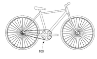
Figure 1 shows a typical bicycle.
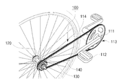
Fig. 2 shows a power transmission device of the bicycle shown in Fig. 1. Fig.
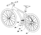
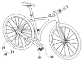
Figures 3 and 4 are perspective views of embodiments of the present invention.
Figure 5 shows the dependent means of the embodiment according to the invention.
DETAILED DESCRIPTION OF THE PREFERRED EMBODIMENTS Hereinafter, a configuration and an operation of an embodiment of the present invention will be described with reference to the accompanying drawings.
3 and 4, the present embodiment includes a
The
Both ends of the
To this end, in this embodiment, the
The
The operation state of the embodiment according to the present invention will be described below. First, when the
On the other hand, when the
5 is a cross-sectional view showing the inside of the
The speed increasing means according to the invention consists of a planetary gear set comprising a satellite gear, a ring gear and a sun gear.
The planetary gear set is widely used as a bicycle transmission means composed of a drive gear, a fixed gear and a driven gear. In the conventional bicycle transmission means, the sun gear is constituted by a fixed gear, and either the satellite gear or the ring gear is constituted by a drive gear.
However, the speed increasing means according to the present invention comprises a ring gear as a fixed gear, a satellite gear as a drive gear, and a sun gear as a driven gear. That is, although the planetary gear set has been utilized for shifting in the past, it is one of the features of the present invention in that there is no technique for utilizing the ring gear as a fixed gear.
The speed increasing means of the present invention comprises a planetary gear that is fixed to the hub shaft, the planetary gear is constituted by a driving gear that rotates in conjunction with the hub axle, and the sun gear comprises a driven gear And the rotational force of the increased sun gear is transmitted to the hub shell through the clutch means.
Hereinafter, an embodiment of the speed increasing means according to the present invention will be described in detail.
The present embodiment is characterized in that the ring gear R provided in the
More specifically, one side of the first carrier C1 is installed to face the
The first sun gear Sa1 axially coupled to the first carrier C1 meshes with the ring gear R and the first sun gear S1, respectively.
The second carrier C2 installed adjacent to the first carrier C1 is provided with a second satellite gear Sa2 which is connected to the ring gear R and the second sun gear Sa2, And is engaged with the gear S2. And the second carrier C2 is engaged with the first sun gear S1.
The third carrier C3 disposed adjacent to the second carrier C2 is provided with a third planet gear Sa3 and the third planet gear Sa3 is disposed between the ring gear R and the third sun gear Sa3, (S3). The third carrier C3 is coupled to the second sun gear S2.
One side of the third sun gear S3 engages with the third planet gear Sa3 and the other side of the third sun gear S3 engages with the clutch means 44. [
The operating state of the speed increasing means constructed as described above will be described.
First, when the
When the first sun gear S1 rotates, the second carrier C2 coupled to the first sun gear S1 rotates, and the second sun gear Sa2 engaged with the fixed ring gear R is rotated Thereby causing the second sun gear S2 to perform the increased speed rotation.
When the second sun gear S2 rotates, the third carrier C3 coupled thereto rotates, and the rotation of the third carrier C3 is transmitted to the fixed ring gear R And rotates the third satellite gear Sa3 engaged. When the third sun gear Sa3 rotates, the third sun gear S3 meshing with the third sun gear S3 rotates at an increased speed. The rotational force of the increased third sun gear S3 is transmitted through the clutch means 44 Thereby rotating the
The number of gear teeth of the sun gears S1 to S3 and the planetary gears Sa1 to Sa3 and the ring gear R is adjusted while the rotational force of the
When the
On the other hand, the clutch means 44 and the second clutch means 45 may be constituted by ratchet teeth or a clutch bearing.
The present invention is not limited to the above-described embodiments, and various modifications and changes may be made thereto without departing from the scope of the present invention.
For example, without a pedal link, the crankshaft can also operate through up and down movement of the pedal. It goes without saying that the speed increasing means can be changed into various forms.
10: Pedal 20: Pedal link
30: crankshaft 31: first crank
32: second crank 40: hub
41: hub shaft 42: hub shell
43: hub axle 44: clutch means
45: second clutch means
S1 to S3: First to third sun gears
C1 to C3: first to third carriers
Sa1 to Sa3: First to third satellite gears
R: Ring gear
Claims (7)
And a pair of crankshafts, one end of which is connected to the hub axle and the other end of which is connected to the pedal shaft and rotates the hub axle by a predetermined angle by rotation of the pedal.
Wherein the crankshaft includes a first crank coupled to the hub axle and a second crank coupled to the pedal shaft, the length of the crankshaft being variable.
And a speed increasing means for increasing the rotational force of the hub shell is further provided inside the hub.
The speed-
A satellite gear that is a driving gear that rotates in conjunction with the hub axle,
A ring gear which is a fixed gear fixed to the hub shaft,
And a sun gear which is a driven gear that is rotated at an increased speed in engagement with the satellite gear,
And the rotational force of the increased sun gear is transmitted to the hub shell through the clutch means.
At least one satellite gear rotating in conjunction with the hub axle;
At least one ring gear fixed to the hub shaft; And
And at least one or more sun gears rotating at an increased speed in engagement with the satellite gear,
And the rotational force of the increased sun gear is transmitted to the hub shell through the clutch means.
And at least one carrier to which the satellite gear is axially coupled is further provided.
Characterized in that a second clutch means is interposed between the hub axle and a carrier adjacent to the hub axle.
Priority Applications (1)
| Application Number | Priority Date | Filing Date | Title |
|---|---|---|---|
| KR20130038241A KR20140121692A (en) | 2013-04-08 | 2013-04-08 | Power transmission device for bicycle and accelerating device |
Applications Claiming Priority (1)
| Application Number | Priority Date | Filing Date | Title |
|---|---|---|---|
| KR20130038241A KR20140121692A (en) | 2013-04-08 | 2013-04-08 | Power transmission device for bicycle and accelerating device |
Publications (1)
| Publication Number | Publication Date |
|---|---|
| KR20140121692A true KR20140121692A (en) | 2014-10-16 |
Family
ID=51993121
Family Applications (1)
| Application Number | Title | Priority Date | Filing Date |
|---|---|---|---|
| KR20130038241A KR20140121692A (en) | 2013-04-08 | 2013-04-08 | Power transmission device for bicycle and accelerating device |
Country Status (1)
| Country | Link |
|---|---|
| KR (1) | KR20140121692A (en) |
-
2013
- 2013-04-08 KR KR20130038241A patent/KR20140121692A/en not_active Application Discontinuation
Similar Documents
| Publication | Publication Date | Title |
|---|---|---|
| EP1620307B1 (en) | Power transmission apparatus for bicycle | |
| KR101903100B1 (en) | Bicycle transmission | |
| AU2011201864A1 (en) | Bicycle with bidirectional input and one-way output transmission combined with crank hole thereof | |
| WO2008090293A3 (en) | Method for changing the gear ratio in a gearbox essentially for hybrid vehicles | |
| JP2007008296A (en) | Bicycle with pedal lever having gear joined with internal gear | |
| KR20090119355A (en) | Drive system for four-wheel bicycle | |
| KR101195422B1 (en) | Accelerator for bicycle for driving speed elevation | |
| CN207496879U (en) | A kind of cone pulley speed change Dual-wheel driving device | |
| KR101955410B1 (en) | Bicycle transmission | |
| US7963878B2 (en) | Hypocycloidal gear train for varying the speed between two shafts and a bicycle having such a hypocycloidal gear train | |
| KR20140121692A (en) | Power transmission device for bicycle and accelerating device | |
| CN207683710U (en) | Poor diameter sun wheel bicycle | |
| US20070234846A1 (en) | Variable geared bicycle pedal | |
| KR20150029320A (en) | Power transmissiong apparatus using link | |
| KR20170036189A (en) | Chainless transmission mechanism for bicycle | |
| CN110382341A (en) | Multistage speed-changing bicycle | |
| KR101793789B1 (en) | Muti-range bycycle | |
| EP3144209B1 (en) | Power transmission device | |
| KR20110117757A (en) | Hub type continuous various transmission and drive wheel having the same | |
| CN2920808Y (en) | Bicycle middle axle mechanism | |
| KR100956067B1 (en) | Power transmission for bicycle | |
| JP2005145419A5 (en) | ||
| KR20130025101A (en) | One way power transmission device of vehicle | |
| KR20120086463A (en) | Power transmission apparatus of bicycle | |
| KR20150062184A (en) | chainless Bicyle |
Legal Events
| Date | Code | Title | Description |
|---|---|---|---|
| E902 | Notification of reason for refusal | ||
| E601 | Decision to refuse application |