KR20140110904A - Respirator made from in-situ air-laid web(s) - Google Patents
Respirator made from in-situ air-laid web(s) Download PDFInfo
- Publication number
- KR20140110904A KR20140110904A KR1020147018620A KR20147018620A KR20140110904A KR 20140110904 A KR20140110904 A KR 20140110904A KR 1020147018620 A KR1020147018620 A KR 1020147018620A KR 20147018620 A KR20147018620 A KR 20147018620A KR 20140110904 A KR20140110904 A KR 20140110904A
- Authority
- KR
- South Korea
- Prior art keywords
- fibers
- mold
- web
- respirator
- mask body
- Prior art date
Links
- RXPKOTQRDGEKFY-UHFFFAOYSA-N CCC(CC)[N+]([O-])=O Chemical compound CCC(CC)[N+]([O-])=O RXPKOTQRDGEKFY-UHFFFAOYSA-N 0.000 description 1
Images
Classifications
-
- A—HUMAN NECESSITIES
- A62—LIFE-SAVING; FIRE-FIGHTING
- A62B—DEVICES, APPARATUS OR METHODS FOR LIFE-SAVING
- A62B23/00—Filters for breathing-protection purposes
- A62B23/02—Filters for breathing-protection purposes for respirators
- A62B23/025—Filters for breathing-protection purposes for respirators the filter having substantially the shape of a mask
-
- A—HUMAN NECESSITIES
- A41—WEARING APPAREL
- A41D—OUTERWEAR; PROTECTIVE GARMENTS; ACCESSORIES
- A41D13/00—Professional, industrial or sporting protective garments, e.g. surgeons' gowns or garments protecting against blows or punches
- A41D13/05—Professional, industrial or sporting protective garments, e.g. surgeons' gowns or garments protecting against blows or punches protecting only a particular body part
- A41D13/11—Protective face masks, e.g. for surgical use, or for use in foul atmospheres
- A41D13/1107—Protective face masks, e.g. for surgical use, or for use in foul atmospheres characterised by their shape
- A41D13/1138—Protective face masks, e.g. for surgical use, or for use in foul atmospheres characterised by their shape with a cup configuration
- A41D13/1146—Protective face masks, e.g. for surgical use, or for use in foul atmospheres characterised by their shape with a cup configuration obtained by moulding
-
- A—HUMAN NECESSITIES
- A62—LIFE-SAVING; FIRE-FIGHTING
- A62B—DEVICES, APPARATUS OR METHODS FOR LIFE-SAVING
- A62B18/00—Breathing masks or helmets, e.g. affording protection against chemical agents or for use at high altitudes or incorporating a pump or compressor for reducing the inhalation effort
- A62B18/02—Masks
-
- A—HUMAN NECESSITIES
- A62—LIFE-SAVING; FIRE-FIGHTING
- A62B—DEVICES, APPARATUS OR METHODS FOR LIFE-SAVING
- A62B18/00—Breathing masks or helmets, e.g. affording protection against chemical agents or for use at high altitudes or incorporating a pump or compressor for reducing the inhalation effort
- A62B18/08—Component parts for gas-masks or gas-helmets, e.g. windows, straps, speech transmitters, signal-devices
- A62B18/084—Means for fastening gas-masks to heads or helmets
-
- B—PERFORMING OPERATIONS; TRANSPORTING
- B29—WORKING OF PLASTICS; WORKING OF SUBSTANCES IN A PLASTIC STATE IN GENERAL
- B29C—SHAPING OR JOINING OF PLASTICS; SHAPING OF MATERIAL IN A PLASTIC STATE, NOT OTHERWISE PROVIDED FOR; AFTER-TREATMENT OF THE SHAPED PRODUCTS, e.g. REPAIRING
- B29C70/00—Shaping composites, i.e. plastics material comprising reinforcements, fillers or preformed parts, e.g. inserts
- B29C70/04—Shaping composites, i.e. plastics material comprising reinforcements, fillers or preformed parts, e.g. inserts comprising reinforcements only, e.g. self-reinforcing plastics
- B29C70/06—Fibrous reinforcements only
- B29C70/10—Fibrous reinforcements only characterised by the structure of fibrous reinforcements, e.g. hollow fibres
- B29C70/12—Fibrous reinforcements only characterised by the structure of fibrous reinforcements, e.g. hollow fibres using fibres of short length, e.g. in the form of a mat
-
- B—PERFORMING OPERATIONS; TRANSPORTING
- B29—WORKING OF PLASTICS; WORKING OF SUBSTANCES IN A PLASTIC STATE IN GENERAL
- B29C—SHAPING OR JOINING OF PLASTICS; SHAPING OF MATERIAL IN A PLASTIC STATE, NOT OTHERWISE PROVIDED FOR; AFTER-TREATMENT OF THE SHAPED PRODUCTS, e.g. REPAIRING
- B29C70/00—Shaping composites, i.e. plastics material comprising reinforcements, fillers or preformed parts, e.g. inserts
- B29C70/04—Shaping composites, i.e. plastics material comprising reinforcements, fillers or preformed parts, e.g. inserts comprising reinforcements only, e.g. self-reinforcing plastics
- B29C70/28—Shaping operations therefor
- B29C70/30—Shaping by lay-up, i.e. applying fibres, tape or broadsheet on a mould, former or core; Shaping by spray-up, i.e. spraying of fibres on a mould, former or core
- B29C70/34—Shaping by lay-up, i.e. applying fibres, tape or broadsheet on a mould, former or core; Shaping by spray-up, i.e. spraying of fibres on a mould, former or core and shaping or impregnating by compression, i.e. combined with compressing after the lay-up operation
- B29C70/342—Shaping by lay-up, i.e. applying fibres, tape or broadsheet on a mould, former or core; Shaping by spray-up, i.e. spraying of fibres on a mould, former or core and shaping or impregnating by compression, i.e. combined with compressing after the lay-up operation using isostatic pressure
-
- D—TEXTILES; PAPER
- D04—BRAIDING; LACE-MAKING; KNITTING; TRIMMINGS; NON-WOVEN FABRICS
- D04H—MAKING TEXTILE FABRICS, e.g. FROM FIBRES OR FILAMENTARY MATERIAL; FABRICS MADE BY SUCH PROCESSES OR APPARATUS, e.g. FELTS, NON-WOVEN FABRICS; COTTON-WOOL; WADDING ; NON-WOVEN FABRICS FROM STAPLE FIBRES, FILAMENTS OR YARNS, BONDED WITH AT LEAST ONE WEB-LIKE MATERIAL DURING THEIR CONSOLIDATION
- D04H1/00—Non-woven fabrics formed wholly or mainly of staple fibres or like relatively short fibres
- D04H1/40—Non-woven fabrics formed wholly or mainly of staple fibres or like relatively short fibres from fleeces or layers composed of fibres without existing or potential cohesive properties
- D04H1/54—Non-woven fabrics formed wholly or mainly of staple fibres or like relatively short fibres from fleeces or layers composed of fibres without existing or potential cohesive properties by welding together the fibres, e.g. by partially melting or dissolving
- D04H1/541—Composite fibres, e.g. sheath-core, sea-island or side-by-side; Mixed fibres
- D04H1/5412—Composite fibres, e.g. sheath-core, sea-island or side-by-side; Mixed fibres sheath-core
-
- D—TEXTILES; PAPER
- D04—BRAIDING; LACE-MAKING; KNITTING; TRIMMINGS; NON-WOVEN FABRICS
- D04H—MAKING TEXTILE FABRICS, e.g. FROM FIBRES OR FILAMENTARY MATERIAL; FABRICS MADE BY SUCH PROCESSES OR APPARATUS, e.g. FELTS, NON-WOVEN FABRICS; COTTON-WOOL; WADDING ; NON-WOVEN FABRICS FROM STAPLE FIBRES, FILAMENTS OR YARNS, BONDED WITH AT LEAST ONE WEB-LIKE MATERIAL DURING THEIR CONSOLIDATION
- D04H1/00—Non-woven fabrics formed wholly or mainly of staple fibres or like relatively short fibres
- D04H1/40—Non-woven fabrics formed wholly or mainly of staple fibres or like relatively short fibres from fleeces or layers composed of fibres without existing or potential cohesive properties
- D04H1/54—Non-woven fabrics formed wholly or mainly of staple fibres or like relatively short fibres from fleeces or layers composed of fibres without existing or potential cohesive properties by welding together the fibres, e.g. by partially melting or dissolving
- D04H1/541—Composite fibres, e.g. sheath-core, sea-island or side-by-side; Mixed fibres
- D04H1/5418—Mixed fibres, e.g. at least two chemically different fibres or fibre blends
-
- D—TEXTILES; PAPER
- D04—BRAIDING; LACE-MAKING; KNITTING; TRIMMINGS; NON-WOVEN FABRICS
- D04H—MAKING TEXTILE FABRICS, e.g. FROM FIBRES OR FILAMENTARY MATERIAL; FABRICS MADE BY SUCH PROCESSES OR APPARATUS, e.g. FELTS, NON-WOVEN FABRICS; COTTON-WOOL; WADDING ; NON-WOVEN FABRICS FROM STAPLE FIBRES, FILAMENTS OR YARNS, BONDED WITH AT LEAST ONE WEB-LIKE MATERIAL DURING THEIR CONSOLIDATION
- D04H1/00—Non-woven fabrics formed wholly or mainly of staple fibres or like relatively short fibres
- D04H1/40—Non-woven fabrics formed wholly or mainly of staple fibres or like relatively short fibres from fleeces or layers composed of fibres without existing or potential cohesive properties
- D04H1/54—Non-woven fabrics formed wholly or mainly of staple fibres or like relatively short fibres from fleeces or layers composed of fibres without existing or potential cohesive properties by welding together the fibres, e.g. by partially melting or dissolving
- D04H1/558—Non-woven fabrics formed wholly or mainly of staple fibres or like relatively short fibres from fleeces or layers composed of fibres without existing or potential cohesive properties by welding together the fibres, e.g. by partially melting or dissolving in combination with mechanical or physical treatments other than embossing
-
- D—TEXTILES; PAPER
- D04—BRAIDING; LACE-MAKING; KNITTING; TRIMMINGS; NON-WOVEN FABRICS
- D04H—MAKING TEXTILE FABRICS, e.g. FROM FIBRES OR FILAMENTARY MATERIAL; FABRICS MADE BY SUCH PROCESSES OR APPARATUS, e.g. FELTS, NON-WOVEN FABRICS; COTTON-WOOL; WADDING ; NON-WOVEN FABRICS FROM STAPLE FIBRES, FILAMENTS OR YARNS, BONDED WITH AT LEAST ONE WEB-LIKE MATERIAL DURING THEIR CONSOLIDATION
- D04H1/00—Non-woven fabrics formed wholly or mainly of staple fibres or like relatively short fibres
- D04H1/70—Non-woven fabrics formed wholly or mainly of staple fibres or like relatively short fibres characterised by the method of forming fleeces or layers, e.g. reorientation of fibres
- D04H1/72—Non-woven fabrics formed wholly or mainly of staple fibres or like relatively short fibres characterised by the method of forming fleeces or layers, e.g. reorientation of fibres the fibres being randomly arranged
- D04H1/732—Non-woven fabrics formed wholly or mainly of staple fibres or like relatively short fibres characterised by the method of forming fleeces or layers, e.g. reorientation of fibres the fibres being randomly arranged by fluid current, e.g. air-lay
-
- D—TEXTILES; PAPER
- D04—BRAIDING; LACE-MAKING; KNITTING; TRIMMINGS; NON-WOVEN FABRICS
- D04H—MAKING TEXTILE FABRICS, e.g. FROM FIBRES OR FILAMENTARY MATERIAL; FABRICS MADE BY SUCH PROCESSES OR APPARATUS, e.g. FELTS, NON-WOVEN FABRICS; COTTON-WOOL; WADDING ; NON-WOVEN FABRICS FROM STAPLE FIBRES, FILAMENTS OR YARNS, BONDED WITH AT LEAST ONE WEB-LIKE MATERIAL DURING THEIR CONSOLIDATION
- D04H1/00—Non-woven fabrics formed wholly or mainly of staple fibres or like relatively short fibres
- D04H1/70—Non-woven fabrics formed wholly or mainly of staple fibres or like relatively short fibres characterised by the method of forming fleeces or layers, e.g. reorientation of fibres
- D04H1/76—Non-woven fabrics formed wholly or mainly of staple fibres or like relatively short fibres characterised by the method of forming fleeces or layers, e.g. reorientation of fibres otherwise than in a plane, e.g. in a tubular way
-
- B—PERFORMING OPERATIONS; TRANSPORTING
- B29—WORKING OF PLASTICS; WORKING OF SUBSTANCES IN A PLASTIC STATE IN GENERAL
- B29K—INDEXING SCHEME ASSOCIATED WITH SUBCLASSES B29B, B29C OR B29D, RELATING TO MOULDING MATERIALS OR TO MATERIALS FOR MOULDS, REINFORCEMENTS, FILLERS OR PREFORMED PARTS, e.g. INSERTS
- B29K2105/00—Condition, form or state of moulded material or of the material to be shaped
- B29K2105/25—Solid
-
- B—PERFORMING OPERATIONS; TRANSPORTING
- B29—WORKING OF PLASTICS; WORKING OF SUBSTANCES IN A PLASTIC STATE IN GENERAL
- B29L—INDEXING SCHEME ASSOCIATED WITH SUBCLASS B29C, RELATING TO PARTICULAR ARTICLES
- B29L2031/00—Other particular articles
- B29L2031/48—Wearing apparel
- B29L2031/4807—Headwear
- B29L2031/4835—Masks
Abstract
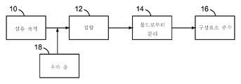
안면부 여과식 호흡기를 제조하는 방법으로서, 상기 방법은 컵 형상 몰드(30)를 제공하는 단계, 상기 몰드(30)가 배치되고 느슨한 섬유(22)들이 성형 챔버(24) 내의 공기 내로 도입되는 성형 챔버(24)를 제공하는 단계, 상기 느슨한 섬유(22)들이 성형 챔버(24) 내의 몰드(30) 상에 축적되도록 하는 단계(10), 및 상기 축적된 섬유들을 섬유 교차 지점에서 서로 접합하는 단계(12)를 포함한다. 본 발명의 방법은 이에 따라 제조 공정에서의 단계를 배제하는데 도움이 된다. 섬유는 또한 마스크 본체 전체에 걸쳐서 균일하게 분포되고, 웨브가 호흡기를 제조하는 동안에 절단되지 않기 때문에, 더 적은 웨브 폐기물이 발생된다.A method of making a face-facing respirator, the method comprising: providing a cup-shaped mold (30); placing the mold (30) and loosening fibers (22) into a molding chamber (10) allowing the loose fibers (22) to accumulate on the mold (30) in the molding chamber (24), and bonding the accumulated fibers to one another at fiber crossing points 12). The method of the present invention thus helps exclude steps in the manufacturing process. The fibers are also uniformly distributed throughout the mask body and less web waste is generated because the web is not cut during the manufacture of the respirator.
Description
본 발명은 마스크 본체를 포함하는 섬유질 웨브들 중 적어도 하나가 몰드 자체에 형성되는 안면부 여과식 호흡기를 제조하는 방법에 관한 것이다.The present invention is directed to a method of making a face-top respirator in which at least one of the fibrous webs comprising the mask body is formed in the mold itself.
통상, 작업자는 2가지 목적, 즉 (1) 불순물 또는 오염물이 착용자의 호흡관으로 들어가는 것을 방지하는 것; 및 (2) 다른 사람 또는 물건이 착용자에 의해 내쉬어진 병원체 및 다른 오염물에 노출되는 것을 보호하는 것 중 적어도 한 가지의 목적을 위해 작업자의 코와 입에 걸쳐 호흡기를 착용한다. 첫 번째 상황에서, 마스크는 예를 들어 자동차 정비소 내에서와 같이 공기가 착용자에게 유해한 입자를 함유하는 환경에서 착용된다. 두 번째 상황에서, 마스크는 예를 들어 수술실 또는 청정실 내에서와 같이 내쉰 오염물에 또 다른 사람 또는 물건이 노출될 수 있는 곳에서 착용된다.Typically, the operator has two objectives: (1) to prevent impurities or contaminants from entering the wearer ' s breathing tube; And (2) the respirator is worn over the nose and mouth of the worker for at least one purpose of protecting another person or object from exposure to pathogens and other contaminants released by the wearer. In the first situation, the mask is worn in an environment where the air contains particles harmful to the wearer, such as in an automotive garage, for example. In the second situation, the mask is worn where other people or objects may be exposed to the polluted pollutants, such as in the operating room or clean room.
일부 호흡기는 마스크 본체 자체가 여과 메커니즘으로서 기능하기 때문에, "안면부 여과식" 호흡기로서 분류된다. 부착가능한 필터 카트리지 또는 필터 라이너(예를 들어, 유샤크(Yuschak) 등의 미국 특허 제RE39,493호 및 타예비(Tayeb)의 미국 특허 제5,094,236호 참조) 또는 삽입 몰딩된 필터 요소(예를 들어, 브라운(Braun)의 미국 특허 제4,790,306호 참조)와 함께 고무 또는 탄성중합체 마스크 본체를 사용하는 호흡기와는 달리, 안면부 여과식 호흡기는 필터 매체가 전체 마스크 본체의 대부분에 걸쳐 연장되어 필터 카트리지를 설치하거나 또는 교체할 필요가 없다. 이에 따라, 안면부 여과식 호흡기는 중량 면에서 상대적으로 가볍고 사용하기 쉽다.Some respirators are categorized as respirators with a "facial filtration" because the mask itself acts as a filtration mechanism. Attachable filter cartridges or filter liners (see, for example, U.S. Patent RE39,493 to Yuschak et al. And U.S. Patent No. 5,094,236 to Tayeb) or insert molded filter elements Unlike a respirator that uses a rubber or elastomeric mask body in conjunction with a brace (see, for example, US Pat. No. 4,790,306 to Braun), a face-face respirator has filter media extending across most of the entire mask body, Or need to be replaced. As a result, the face-type respirator is relatively light in weight and easy to use.
안면부 여과식 호흡기는 통상적으로 열 접합 섬유로부터 제조된다. 열 접합 섬유는 가열 및 냉각된 이후에 인접한 섬유에 접합된다. 이러한 섬유로부터 형성된 안면부 여과식 호흡기의 예는 다이루드(Dyrud) 등의 미국 특허 제4,807,619호, 및 베르그(Berg)의 미국 특허 제4,536,440호에 도시된다. 이들 특허에 개시된 호흡기는 열 접합 섬유의 하나 이상의 층을 갖는 컵 형상 마스크이다. 열 접합 섬유의 층은 "형상화 층"으로 지칭되고, 여과 층에 대한 지지부 및 마스크에 형상을 제공하기 위해 사용된다. 미국 특허 제4,807,619호 및 제4,536,440호에 개시된 형상화 층은 가열된 몰드 내에서 열 접합 섬유의 부직포 웨브를 몰딩함으로써 제조된다. 가열된 몰드는 열 접합 섬유의 접합 성분의 연화점 초과의 온도에서 작용한다. 열 접합 섬유의 웨브는 가열된 몰드 내에 배치되고, 안면 마스크에 대한 형상화 층을 형성하기 위해 압력과 열에 노출된다. 이 종류의 몰딩 작업은 "열간 몰딩 공정"으로 알려졌다.Facial respirators are typically made from thermally bonded fibers. The thermally bonded fibers are bonded to adjacent fibers after being heated and cooled. Examples of face-face respirators formed from such fibers are shown in U.S. Patent No. 4,807,619 to Dyrud et al. And U.S. Patent No. 4,536,440 to Berg. The respirators disclosed in these patents are cup-shaped masks having one or more layers of thermally bonded fibers. The layer of thermally-bonded fibers is referred to as a "shaped layer" and is used to provide support for the filtration layer and shape to the mask. The shaping layers disclosed in U.S. Patent Nos. 4,807,619 and 4,536,440 are fabricated by molding nonwoven webs of thermally bonded fibers in a heated mold. The heated mold acts at a temperature above the softening point of the bonding component of the thermally bonded fibers. The web of thermally bonded fibers is placed in a heated mold and exposed to pressure and heat to form a shaped layer for the face mask. This kind of molding work was known as the "hot molding process".
안면부 여과식 호흡기는 또한 미리 제조된 부직포 웨브가 우선 가열되고 그 후에 가열된 상태에서 "냉간 몰드" 내에 배치되는 "냉간 몰딩 공정"에 의해 제조된다. 몰드는 "냉간"인 것으로 지칭되는데, 이는 몰딩 부재가 웨브 내의 열 접합 섬유의 연화점 미만의 온도에 있기 때문이다. 냉간 몰딩 공정의 예는 크론저(Kronzer) 등의 미국 특허 제7,131,442B1호에 개시된다 - 또한 스코브(Skov)의 미국 특허 제4,850,347호 참조 -. 열간 및 냉간 몰딩 작업 둘 모두에서, 몰딩된 웨브는 미리 제조되며, 즉 이는 컵 형상 구조물로의 변환을 위해 몰딩 부재 상에 배치되기 전에 미리 조립된다.The facial air breathing apparatus is also manufactured by a "cold molding process" in which a pre-fabricated nonwoven web is first heated and then placed in a "cold mold" The mold is referred to as being "cold" because the molding member is at a temperature below the softening point of the thermally bonded fibers in the web. An example of a cold molding process is disclosed in U.S. Patent No. 7,131,442B1 to Kronzer et al. - see also US Pat. No. 4,850,347 to Skov -. In both the hot and cold molding operations, the molded web is prefabricated, i. E. It is preassembled before being placed on the molding member for conversion to a cup-shaped structure.
본 발명은 안면부 여과식 호흡기를 제조하는 신규한 방법 및 이러한 방법에 의해 제조된 안면부 여과식 호흡기를 제공하는 것을 목적으로 한다.The present invention aims to provide a novel method for manufacturing a facial air filtering respirator and a facial air filtering respirator manufactured by such a method.
본 발명은 안면부 여과식 호흡기를 제조하는 신규한 방법을 제공한다. 신규한 방법은 (a) 컵 형상 몰드를 제공하는 단계, (b) 상기 몰드가 배치되고 느슨한 섬유들이 성형 챔버 내의 공기 내로 도입되는 성형 챔버를 제공하는 단계, (c) 상기 느슨한 섬유들이 성형 챔버 내의 몰드 상에 축적되도록 하는 단계, 및 (d) 컵 형상 안면부 여과식 호흡기를 형성하기 위해 섬유 교차 지점에서 축적된 섬유들을 서로 접합하는 단계를 포함한다.SUMMARY OF THE INVENTION The present invention provides a novel method of manufacturing a facial air filtration breathing apparatus. The method comprises the steps of: (a) providing a cup-shaped mold; (b) providing a molding chamber in which loose fibers are placed and into which air is introduced into the molding chamber; (c) And (d) bonding the fibers accumulated at the fiber crossing points to each other to form a cup-shaped facial respirator.
본 발명은 또한 원위치 웨브(in situ web), 즉 몰드 자체 상에 형성된 웨브를 포함하는 마스크 본체를 포함한 안면부 여과식 호흡기를 제공한다. 호흡기는 또한 마스크 본체에 고정되는 하니스를 갖는다.The present invention also provides a face-artificial respirator comprising a mask body comprising an in situ web, i.e. a web formed on the mold itself. The respirator also has a harness fixed to the mask body.
본 발명은 마스크 본체를 포함하는 섬유질 웨브(들)가 몰드 상에 형성되는 안면부 여과식 호흡기를 제조하는 공지된 방법과 상이하다. 공지된 호흡기 제조 공정에서, 마스크 본체를 포함하는 부직포 섬유질 웨브는 미리제조되며, 즉 몰드 상에 배치되기 전에 조립된다. 본 발명에서, 마스크 본체의 하나 이상의 웨브는 마스크 본체가 제조되는 몰드 상에서 조립된다. 따라서, 본 발명의 방법은 제조 공정에서 단계를 배제하는데 있어서 도움이 된다. 호흡기를 제조하기 위해 사용되는 부직포 웨브는 미리-조립, 운반, 펼쳐짐, 절단 및 호흡기 마스크 본체 조립 공정으로 도입될 필요가 없다. 생성된 호흡기는 또한 마스크 본체 전체에 걸쳐서 더욱 균일하게 분포되는 섬유를 가질 수 있다. 웨브 내의 섬유는 마스크 본체를 포함하는 웨브가 몰드 자체 상에 형성되기 때문에 몰드 상에 이의 배치 상태로부터 연신되지 않을 수 있다. 그리고, 웨브가 호흡기의 조립 동안에 절단되지 않기 때문에, 호흡기 제조 공정에서 웨브 폐기물이 더 적게 발생될 수 있다. 성형 챔버 내에서 사용되지 않는 섬유는 수집될 수 있고 챔버 내로 재도입될 수 있다.The present invention differs from known methods of manufacturing a face-through breathing apparatus in which a fibrous web (s) comprising a mask body is formed on a mold. In a known respirator manufacturing process, the nonwoven fibrous web comprising the mask body is prefabricated, i. E. Assembled before being placed on the mold. In the present invention, one or more webs of the mask body are assembled on the mold from which the mask body is made. Thus, the method of the present invention is helpful in excluding steps in the manufacturing process. The nonwoven web used to make the respirator need not be pre-assembled, transported, unfolded, cut and introduced into the respirator mask body assembly process. The resulting respirator may also have fibers that are more evenly distributed throughout the mask body. The fibers in the web may not be stretched from their placement on the mold because the web comprising the mask body is formed on the mold itself. And, since the web is not cut during assembly of the respirator, fewer web waste can be generated in the respirator manufacturing process. Unused fibers in the forming chamber can be collected and reintroduced into the chamber.
용어해설Glossary of terms
이하에 기술되는 용어는 다음과 같이 정의된 의미를 가질 것이다:The terms described below will have the following defined meanings:
"활성 미립자"는 화학적 특성, 예컨대 촉매 및 이온 교환을 포함하는 일부 특징 및 특성에 기인할 수 있는 수착(흡착 및/또는 흡수)과 같은 일부 작용 또는 기능을 수행하기에 특히 적합한 입자 또는 과립을 의미하고,"Active particulate" means a particulate or granule particularly suitable for carrying out some action or function, such as sorption (adsorption and / or absorption), which can be attributed to chemical properties such as catalyst and some characteristics and characteristics including ion exchange and,
"2성분 섬유"는 상이한 연화 온도를 갖는 상이한 중합체 조성물을 포함한 둘 이상의 성분으로 구성된 섬유를 의미하고 - 상기 성분은 섬유의 길이를 따라 개별 및 별개의 영역에 배열됨 -,"Bicomponent fiber" means a fiber composed of two or more components, including different polymer compositions having different softening temperatures, the components being arranged in separate and distinct regions along the length of the fibers,
"결합제 섬유"는 열 접합가능 섬유를 의미하고,"Binder fiber" means a thermally bondable fiber,
"포함하다(또는 포함하는)"는 특허 용어에서 표준인 것과 같은 그의 정의를 의미하는데, "구비하다", "갖는", 또는 "함유하는"과 대체로 동의어인 개방형 용어이다. "포함하다", "구비하다", "갖는", "함유하는" 및 이들의 변형이 통상적으로 사용되는 개방형 용어이지만, 본 발명은 또한 본 발명의 호흡기의 그의 의도된 기능을 제공하는 데 있어서의 성능에 대해 악영향을 미치는 것 또는 요소만을 배제한다는 점에서 반개방형 용어인 "본질적으로 ~로 이루어진"과 같은 더 좁은 용어를 사용하여 적합하게 설명될 수도 있고,"Included (or included)" means its definition as being standard in the patent term, and is an open term broadly synonymous with "having," "having," or "containing". It is to be understood that although the terms "comprises", "having", "having", "containing" and variations thereof are commonly used open terms, the present invention also encompasses the use of the respiratory apparatus of the present invention May be suitably described using narrower terms such as " consisting essentially of, " which is a semi-open term in that it adversely affects performance or excludes elements only,
"청정 공기"는 여과되어 오염물질을 제거한 다량의 대기 중의 주위 공기를 의미하며,"Clean air" means a large amount of ambient air in the atmosphere that has been filtered and removed contaminants,
"오염물"은 대체로 입자(예를 들어, 유기 증기 등)인 것으로 여겨지지 않을 수 있지만 호기 유동 스트림 내의 공기를 포함하는 공기 내에 현탁될 수 있는 입자(먼지, 안개 및 연무를 포함함) 및/또는 다른 물질을 의미하고,"Contaminants" include particles (including dust, fog, and mist) that may not be considered to be particles (eg, organic vapors, etc.) but that can be suspended in air containing air in the exhalation flow stream and / Means a different substance,
"커버 웨브"는 주요하게 오염물을 여과하도록 설계되지 않은 부직포 섬유질 층을 의미하고,"Cover web" means a non-woven fibrous layer that is not primarily designed to filter contaminants,
"컵 형상"은 제품이 중실 구조일 경우 상향 개방 단부와 함께 수직으로 배치된 경우 액체를 보유할 수 있는 형상을 갖는 것을 의미하고,"Cup shape" means having a shape capable of retaining liquid when vertically disposed with the upwardly open end when the product is a solid structure,
"외부 기체 공간"은 내쉰 기체가 마스크 본체 및/또는 호기 밸브를 통해 이를 지나 통과한 후에 들어가는 주위 대기 기체 공간을 의미하고,"External gas space" means an ambient atmospheric gas space into which the respiratory gas enters after passing through the mask body and / or the exhalation valve,
"섬유" 또는 "섬유들"은 천연으로 제조되거나 또는 합성으로 제조된 가느다란 신장된 구조물(들)을 의미하고,"Fiber" or "fibers" means a finely elongated structure (s) made either naturally or synthetically,
"안면부 여과식"은 마스크 본체 자체가 그를 통과하는 공기를 여과하도록 설계되어, 이러한 목적을 달성하기 위해 마스크 본체에 부착되거나 또는 그 내에 몰딩되는 별도의 식별가능한 필터 카트리지, 필터 라이너 또는 삽입 몰딩된 필터 요소가 존재하지 않는 것을 의미하고,"Facial filtration" refers to a separate, identifiable filter cartridge, filter liner, or insert molded filter that is designed to filter air through the mask body itself and that is attached to or molded within the mask body to achieve this purpose Means that the element does not exist,
"필터" 또는 "여과 층"은 공기 투과성 재료의 하나 이상의 층을 의미하며, 층(들)은 그를 통과하는 공기 스트림으로부터 (입자와 같은) 오염물을 제거하는 주된 목적을 위해 구성되고,"Filter" or "filtration layer" means one or more layers of an air permeable material, the layer (s) being configured for the primary purpose of removing contaminants (such as particles)
"여과 구조물"은 주로 공기를 여과시키기 위해 설계되는 구성물을 의미하고,"Filtration structure" refers primarily to a composition designed to filter air,
"성형 챔버"는 섬유가 이러한 축적을 위해 의도된 표면 상에 축적될 수 있는 정해진 또는 정해질 수 있는 부피의 공간을 의미하고,"Molding chamber" means a space of a defined or determinable volume where the fibers can be deposited on the intended surface for such accumulation,
"하니스"는 마스크 본체를 착용자의 안면 상에 지지하는 것을 보조하는 구조물 또는 부품들의 조합을 의미하고,"Harness" means a structure or combination of parts that assists in supporting the mask body on the wearer ' s face,
"원위치"는 몰딩이 수행되는 몰드 상에서 제조되는 것을 의미하고,"In situ" means produced on a mold on which molding is performed,
"일체형"은 해당 부품들이 후속하여 함께 결합되는 2개의 별개의 부품들이 아니라 단일 부품으로서 동시에 제조되었음을 의미하고,"Integral" means that the components are manufactured simultaneously as a single component rather than two separate components that are subsequently joined together,
"내부 기체 공간"은 마스크 본체와 사람의 안면 사이의 공간을 의미하고,The term "inner gas space" means the space between the mask body and the face of a person,
"느슨한 섬유"는 웨브 형태로 조립되지 않는 섬유를 의미하고,"Loose fibers" means fibers that are not assembled in web form,
"마스크 본체"는, 사람의 코와 입 위에 맞게 설계되며 외부 기체 공간으로부터 분리된 내부 기체 공간을 형성하는 데 도움을 주는 공기 투과성 구조물을 의미하고,"Mask body" means an air permeable structure designed to fit over the nose and mouth of a person and to help form an internal gas space separated from the external gas space,
"몰드"는 열 및/또는 압력의 인가에도 불구하고 원하는 형상 또는 구성으로 제품을 형성하기 위하여 사용되는 장치를 의미하며,"Mold" means a device used to form a product in a desired shape or configuration despite the application of heat and / or pressure,
"비열 접합"은 비열 접합된 섬유가 수용되는 웨브를 몰딩하기에 적합한 온도로 가열한 후에 인접한 접촉 섬유에 섬유가 실질적으로 접합되지 않는 것을 의미하고,By "nonthermal bonding" is meant that the fibers are not substantially bonded to adjacent contact fibers after heating to a temperature suitable for molding the web from which the nonthermalized fibers are received,
"부직포"는 웨브 성분이 위빙(weaving) 이외의 수단에 의해 서로 고정되는 구조물 또는 구조물의 일부를 의미하고,"Nonwoven fabric" means a structure or part of a structure in which web components are secured to each other by means other than weaving,
"중합체" 및 "가소성"은 각각 주로 하나 이상의 중합체를 포함하고 또한 다른 성분을 함유할 수 있는 재료를 의미하고,"Polymer" and "plastic" refer to materials, respectively, that contain primarily one or more polymers and may also contain other components,
"다공성"은 공기 투과성을 의미하며,"Porous" means air permeability,
"복수의"는 2개 이상을 의미하고,"Plural" means two or more,
"호흡기"는 호흡하는 착용자에 대해 청결한 공기를 제공하기 위하여 코와 입에 걸쳐 안면에 사람이 착용하는 공기 여과 장치를 의미하고,"Respiratory" means an air filtration device that is worn by a person in the face across the nose and mouth to provide clean air to the breathing wearer,
"형상화 층"은 정상적인 취급에서 원하는 형상(및 형상화 층에 의해 지지되는 다른 층의 형상)을 유지하기에 충분한 구조적 보전성을 갖는 층을 의미하고,"Shaped layer" means a layer having sufficient structural integrity to maintain the desired shape (and the shape of the other layer supported by the shaping layer) in normal handling,
"연화 온도"는 냉각 시에 접합된 상태로 유지되고 섬유 성분이 또 다른 섬유에 접합되도록 허용되는 정도로 섬유 성분이 연화되는 최저 온도를 의미하고,"Softening temperature" means the lowest temperature at which the fiber component is softened to such an extent that it remains bonded during cooling and the fiber component is allowed to bond to another fiber,
"스테이플 섬유"는 한정된 길이의 섬유를 의미하고,"Staple fibers" means fibers of defined length,
"기재"는 아래에 배치되는 층을 의미하며,"Substrate" means a layer disposed below,
"흡입"은 낮은 압력 또는 진공(전체적으로 또는 부분적으로)을 생성함으로써 또는 이와는 달리 기류를 생성함으로써 내부로 또는 이를 통하여 인입되는 것을 위미하고,"Suction" is intended to be introduced into or through the interior by creating a low pressure or vacuum (in whole or in part)
"상부층"은 위에 배치되는 층을 의미하고,"Upper layer" means a layer disposed over,
"열 접합 (또는 접합가능한) 섬유"는 이의 연화 온도 초과의 온도로 가열하고 그 후에 냉각된 뒤에 인접한 접촉 섬유에 접합되는 섬유를 의미하고, 및"Thermally bonded (or bondable) fiber" means a fiber that is heated to a temperature above its softening temperature and then cooled and then bonded to adjacent contact fibers, and
"웨브"는 공기 투과성이며, 3차원이기보다는 2차원으로 상당히 더 큰 수동 취급가능 구조물을 의미한다."Web" refers to a passive structure that is air permeable and considerably larger in two dimensions rather than three dimensions.
도 1은 본 발명에 따르는 방법에서 사용될 수 있는 단계의 개략도.
도 2는 본 발명에 따르는 호흡기를 제조하는 방법의 개략도.
도 3은 본 발명에 따르는 호흡기(40)의 사시도.
도 4는 호흡기 마스크 본체(42)를 통해 취한 단면도.
[발명의 실시를 위한 구체적인 내용]
본 발명을 실시함에 있어서, 안면부 여과식 호흡기를 제조하는 신규한 방법이 제공되며, 이 방법은 컵 형상 몰드를 제공하는 단계, 몰드가 배치되고 느슨한 섬유들이 그 내부에 도입되는 성형 챔버(예컨대, 룸(room) 또는 밀폐된 영역)를 제공하는 단계, 느슨한 섬유들이 몰드 상에 축적되도록 하는 단계, 및 섬유 교차 지점에서 섬유들을 서로 접합하는 단계를 포함한다. 일회용 호흡기를 몰딩하는 통상적인 방법에 있어서, 일반적으로 평평하고 접합된 부직포 사전-조립 웨브가 몰드 내에서 가열된 상태에서 압축된다. 이러한 압력에 노출 시에, 상기 웨브는 연신 및 변형될 수 있어서 몰딩된 제품 내에서 웨브 균일성 문제가 야기된다. 또한, 둥근 호흡기 형상이 호흡기 제조 동안에 평평한 웨브로부터 절단될 때, 상당한 폐기물이 발생될 수 있다.
본 명세서에 기재된 공정은 이들 문제점을 줄일 수 있다. 열 접합 이전에 또는 열 접합 중에 원하는 호흡기 형상으로의 웨브의 직접 성형은 웨브 균일성을 저하시킬 수 있는 추가 후-접합 처리에 대한 필요성을 경감시킨다. 축적된 섬유가 열 접합되기 전에 호흡기 형상을 성형하는 것은 또한 접합 이전에 과잉의 재료를 제거하고 재료가 폐기되는 대신에 재사용되도록 허용하는 가능성을 제공한다. 추가로, 우수한 경제적 및 환경적 실행을 호흡기 제조에 추가로 확립하는 방식으로서 재사용된 섬유질 스크랩 재료 또는 다른 재활용된 재료를 통합시키기 위해 이 공정을 이용할 수 있다.
도 1에는 안면부 여과식 호흡기가 본 발명에 따라 제조될 수 있는 방식의 예시가 도시된다. 컵 형상 몰드는 느슨한 섬유들이 몰드 상에 축적되는(10) 성형 챔버 내에 배치된다. 축적은 예를 들어, 다공성 몰드를 통하여 성형 챔버 내에 공기를 인입하는(draw) 부분 진공을 이용하여 촉진될 수 있다. 대안으로 또는 추가로, 몰딩 부재는 섬유들이 진공, 블로워 및/또는 중력 운동으로부터 이러한 접촉을 이룰 때 섬유들이 몰드 상에 잔류시키는 수단을 가질 수 있다. 섬유 축적을 촉진시키기 위한 이러한 수단은 섬유들이 접촉하는 몰드의 외부 표면 상에 배치된 거친 텍스처(roughened texture) 또는 작은 핀(small pin)을 포함할 수 있다. 느슨한 섬유는 성형 챔버 내로 블로잉, 드로잉 또는 드로핑될 수 있다. 느슨한 섬유들이 성형 챔버 전체에 걸쳐 이동함에 따라, 이 섬유들은 몰드의 외부 표면과 접촉할 수 있다. 텍스처화된 표면은 섬유들이 몰딩 부재와 접촉한 상태로 유지되도록 하거나 또는 이 위에 축적되도록 한다. 성형 챔버의 하부 또는 어디든 다른 곳에 축적되는 과잉의 느슨한 섬유는 성형 챔버로부터 제거될 수 있고, 폐기물을 배제하거나 또는 최소화하기 위해 나중에 성형 챔버 내로 재도입될 수 있다.
느슨한 섬유들이 몰드 상에 축적되면, 섬유들은 섬유 교차 지점에서 서로 접합된다(12). 접합은 섬유의 하나 이상의 접합 성분(들)의 연화 온도 초과의 온도로 축적된 섬유를 가열함으로써 달성될 수 있다. 섬유들이 충분히 접합되면, 생성된 몰딩된 마스크 본체가 몰드로부터 분리될 수 있다(14). 하니스가 그 뒤에 몰딩된 마스크 본체에 부착되어(16) 오염물이 주변 공기로부터 여과될 필요가 있는 환경에서 사용하기에 적합한 안면부 여과식 호흡기가 형성될 수 있다. 대안으로, 하니스는 마스크 본체가 몰드로부터 분리되기 전에 마스크 본체에 부착될 수 있다. 호기 밸브가 또한 이와 같이 원하는 경우 마스크 본체에 부착될 수 있다. 필터 재료의 추가 층 또는 형상화 층이 또한 성형 챔버 내의 섬유들이 몰드 상에 배치되기 이전에 또는 이후에 몰드 상에 도입될 수 있다(18). 따라서, 추가 층이 몰드 상에 형성되는 에어 레이드 웨브에 대한 기재 또는 상부층(suprastrate)이 될 수 있다. 추가 층이 또한 성형 챔버 내의 몰드 상에 형성된 섬유질 웨브의 일 측면 또는 양 측면에 배치된 커버 웨브일 수 있다. 추가 층(18)의 도입이 섬유가 몰드 상에 축적된 이후에 발생되는 바와 같이 도시될지라도, 추가 층은 이러한 축적 이전에(기재와 같이) 또는 접합 단계 이후에(상부층과 같이) 도입될 수 있다.
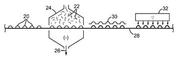
도 2는 본 발명의 공정이 생성된 마스크 본체의 하나 이상의 층을 조립하기 위하여 사용되는 느슨한 섬유(22)를 수집하도록 호흡기 마스크 본체의 형상으로 다공성 몰드(20)를 사용할 수 있는 것을 도시한다. 마이크로섬유, 접합 섬유, 및 스테이플 섬유와 같은 느슨한 섬유(22)들의 혼합물이 성형 챔버(24) 내로 전달될 수 있다. 또한 공기가 다공성 몰드(20)를 통해 흡입되도록 하기 위해 공기가 성형 챔버(24)로부터 인입될 수 있다(26). 성형 챔버 내의 공기가 다공성 몰드를 통하여 인입될 때, 성형 챔버(24) 내의 느슨한 섬유(22)들은 이들 몰드 상에서 동축을 이룬다. 몰드는 이 위에 스크린 또는 다른 다공성 매질을 가질 수 있어서 다공성 몰드를 형성한다. 다공성 매질은 의도된 마스크 본체의 형상으로 구성된다. 다공성 몰드는 이 몰드가 성형 챔버(24)에 유입되기 전에 또는 유입됨에 따라 이동식 진공 벨트(28) 상에 배치될 수 있다. 진공 벨트(28)가 성형 챔버(24)를 가로질러 몰드(20)를 이동시킬 때, 응축기 팬과 같은 팬이 몰드(20)를 통하여 성형 챔버(24)로부터 공기를 끌어당길 수 있다(26). 성형 챔버(24) 내의 생성된 공기 움직임은 몰드(22)를 향하여 느슨한 섬유들을 인입시켜 느슨한 섬유들이 몰드 표면 상에 또는 이에 대해 배치되는 미리제조된 웨브의 표면 상에 포획되도록 한다. 성형 챔버(24)는 창문 또는 유리 측벽과 같은 하나 이상의 투명 부분을 포함할 수 있어서 마스크 쉘의 제조를 담당하는 사람이 섬유 수집 공정을 볼 수 있다. 몰드(20)가 성형 챔버(24)를 가로질러 이동한 후에, 제2 세트의 몰드(30)가 축적된 섬유를 제 위치에 보유하기 위하여 제1 몰드(20)에 걸쳐서 배치될 수 있다. 그 후에, 몰딩된 웨브가 몰드로부터 제거되면 접합된 섬유가 원하는 호흡기 형상을 유지하도록 몰드-섬유-몰드 개재물이 섬유들을 서로 접합시키기 위해 오븐 내에 또는 가열 유닛(32) 아래에 배치될 수 있다. 몰딩된 제품의 평량은 느슨한 섬유 공급 속도, 컨베이어의 속도, 및 다공성 몰드를 통한 기류량(air flow rate)을 변화시킴으로써 제어될 수 있다. 본 발명의 공정은 또한 웨브가 3차원 형상으로 형성됨에 따라 활성 탄소와 같은 활성 미립자를 느슨한 섬유 공급 스트림 내로 추가할 수 있도록 한다. 이 단계는 트렌드(Trend) 등의 미국 특허 출원 제2006/0254427A1호에 기재된 입자-함유 섬유질 웨브와 같은 활성 미립자 또는 다른 첨가된 성분을 함유하는 완성된 호흡기를 제조하기 위해 필요한 기계의 복잡성 및 공정 단계의 수를 줄일 수 있다. 추가로, 둘 이상의 성형 챔버가 순차적으로 배치될 수 있어서 복수의 층(1개, 2개, 3개, 4개, 또는 5개 또는 더 많은 개수의 층)이 조립될 수 있다. 따라서, 제1 성형 챔버는 마스크 본체에 대한 하부에 배치된 형상화 층을 형성하기 위해 사용될 수 있는 반면 제2 성형 챔버는 여과 층을 형성하기 위하여 사용될 수 있고, 제3 성형 챔버는 커버 웨브를 형성하기 위해 사용될 수 있다. 따라서, 둘 이상의 섬유질 웨브가 연속적인 성형 챔버 내의 몰드 상에 형성될 수 있고, 복수의 웨브가 예를 들어 초음파 용접에 의해 주연부에서 서로 고정될 수 있다.
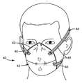
도 3은 본 발명에 따라 제조될 수 있고 마스크 본체(42) 및 마스크 하니스(44)를 포함하는 안면부 여과식 호흡 마스크(40)의 예를 도시하고 있다. 하니스(44)는 탄성 재료로 제조될 수 있는 하나 이상의 스트랩(46)을 포함할 수 있다. 하니스 스트랩(46)은 접착제 수단, 접합 수단, 또는 기계적 수단(예를 들어, 카스티글리온(Castiglione)의 미국 특허 제6,729,332호 참조)을 비롯한 다양한 수단으로 마스크 본체(42)에 고정될 수 있다. 하니스(46)는 예를 들어 마스크 본체에 초음파 용접되거나 또는 마스크 본체에 스테이플러로 고정될 수 있다. 가능하게는 사용될 수 있는 다른 하니스의 예는 브로스트롬(Brostrom) 등의 미국 특허 제5,394,568호 및 세팔라(Seppala) 등의 미국 특허 제5,237,986호 및 브로스트롬 등의 제EP 608684A호에 기재된다.마스크 본체(42)는 코의 콧마루 위에, 볼을 가로질러 그리고 볼 주위에, 그리고 턱 아래에서 착용자의 안면과 접촉하도록 형상화되는 주연부(48)를 갖는다. 마스크 본체(42)는 착용자의 코와 입 주위에 밀폐된 내부 기체 공간을 형성하고, 도면에 도시된 바와 같이 곡선 반구형 형상을 취할 수 있거나 또는 원하는 바에 따라 다른 형상을 취할 수 있다. 예를 들어, 형상화 층 및 이에 따라 마스크 본체는 자푼티치(Japuntich)의 미국 특허 제4,827,924호에 개시된 안면 여과식 마스크와 같은 컵 형상 구성을 가질 수 있다. 가단성 코 클립이 이의 상부 에지에 대해 중심에 인접한 마스크 본체(42)의 외부 면에 고정될 수 있어서 마스크가 특정 착용자의 코 위에 알맞게 정합되도록 이 영역에서 변형 또는 형상화될 수 있다. 적합한 코 클립의 예가 카스티글리온의 미국 특허 제5,558,089호 및 제Des. 412,573호에 도시 및 개시된다. 마스크 본체(42)는 또한 제품 파손 저항을 향상시키기 위하여 마스크 본체(42)의 중심 영역의 모든 또는 일부 층을 통하여 연장될 수 있는 선택적 주름진 패턴을 가질 수 있다.
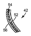
도 4는 마스크 본체(42)가 내부 형상화 층의 반경방향 외향 측면에 필터 재료(54)의 층 및 필터 층(54)의 반경방향 외향 측면에 형상화 층(52)과 같이 또한 일반적인 형상을 취하는 외부 커버 웨브(56)를 갖는 내부 형상화 층(52)을 포함할 수 있는 것을 도시한다. 형상화 층(52)의 기능은 주요하게 필터 층(54)을 지지하고 마스크 본체 형상을 유지시키는 것이다. 형상화 층(52)이 또한 마스크 내로 인입되는 공기를 위한 거친 초기 필터로서 기능을 할 수 있을지라도, 마스크(10)의 주요한 여과 작용은 필터 층(54)에 의해 제공된다. 외부 형상화 층은 또한 외부 커버 웨브(56)와 필터 층(54) 사이의 필터 층(54)의 반경방향 외향 측면에 배치될 수 있다. 도시된 조립 층에 추가로, 마스크 본체(42)는 또한 특히 코 영역에서 마스크 주연부 주위에 발포체 밀봉부를 포함할 수 있다 - 예를 들어, 자푼티치의 미국 특허 제4,827,924호 참조 -. 이러한 밀봉부는 마스크가 착용될 때 착용자의 안면과 접촉하는 써모크로믹 정합-표시 재료(thermochromic fit-indicating material)를 포함할 수 있다. 안면 접촉으로부터의 열은 써모크로믹 재료의 색상이 변화하도록 하여 착용자가 적합한 정합이 이루어진 경우를 결정할 수 있도록 한다 - 스프링젯(Springett) 등의 미국 특허 제5,617,749호 참조 -. 마스크 본체(42)는 또한 형상화 층(52)으로부터 느슨해질 수 있는 임의의 섬유를 포획하고 마스크의 내부 측면에서 착용자에게 향상된 편안함을 제공하기 위하여 내부 커버 웨브가 제공될 수 있다. 이러한 커버 웨브의 구조는 형상화 및 여과 층의 기술내용과 함께 하기에서 기재된다.
형상화 층
형상화 층(들)은 열 및/또는 압력을 사용하여 원하는 형상으로 몰딩될 수 있고 냉각된 때 그의 형상을 유지하는 섬유질 재료의 적어도 하나의 층으로부터 본 발명에 따라 형성될 수 있다. 형상 보유력은 전형적으로, 섬유가 예를 들어, 융합 또는 용접에 의해 이들 사이의 접촉점에서 서로에 접합되도록 함으로써 달성된다. 직접 몰딩된 호흡기 마스크의 형상 유지 층을 제조하기 위한 공지된 임의의 적합한 재료는, 예를 들어 바람직하게는 주름진 합성 스테이플 섬유와 2성분 스테이플 섬유의 혼합물을 포함하는 마스크 쉘을 형성하기 위해 사용될 수 있다. 2성분 섬유는 섬유질 재료의 둘 이상의 별개 영역, 전형적으로 중합체 재료의 별개의 영역을 포함하는 섬유이다. 전형적인 2성분 섬유는 결합제 성분 및 구조적 성분을 포함한다. 결합제 성분은 형상 유지 쉘의 섬유가 가열 및 냉각 시 섬유 교차점에서 함께 접합될 수 있도록 한다. 가열 중에, 결합제 성분이 유동하여 인접한 섬유와 접촉한다. 형상 유지 층은, 예를 들어 0/100 내지 75/25의 범위일 수 있는 중량% 비로 스테이플 섬유와 2성분 섬유를 포함하는 섬유 혼합물로부터 제조될 수 있다. 바람직하게는, 재료는 보다 많은 개수의 교차 접합점들을 생성하도록 적어도 50 중량%의 2성분 섬유를 포함하는데, 이는 이어서 쉘의 탄성 및 형상 보유력을 증가시킨다.
형상화 층에 사용될 수 있는 적합한 2성분 섬유는, 예를 들어 나란한 구성, 동심형 시스 코어(sheath-core) 구성 및 타원형 시스 코어 구성을 포함한다. 적합한 2성분 섬유의 하나는 미국 노스 캐롤라이나 샬롯 소재의 코사(Kosa)로부터 상표명 "코사(KOSA) T254"(12 데니어, 길이 38 mm)로 입수 가능한 폴리에스테르 2성분 섬유이며, 이는 예를 들어 코사로부터 상표명 "T295"(3 데니어, 길이 38 mm)로 입수 가능한 폴리에스테르 스테이플 섬유 및 가능하게는 또한 예를 들어, 코사로부터 상표명 "T259"(15 데니어, 길이 32 mm)로 입수 가능한 폴리에틸렌 테레프탈레이트(PET) 섬유의 조합으로 사용될 수 있다. 대안으로, 2성분 섬유는 일반적으로 아이소프탈레이트 및 테레프탈레이트 에스테르 단량체로부터 형성되는 중합체의 시스에 의해 둘러싸이는 결정 PET의 코어를 갖는 대체로 동심 시스-코어 구성을 포함할 수 있다. 후자의 중합체는 코어 재료보다 낮은 온도에서 열 연화성을 갖는다. 폴리에스테르는, 마스크 복원력에 기여할 수 있고 다른 섬유보다 수분을 적게 흡수할 수 있다는 점에서 이점을 갖는다.
대안으로, 형상화 층은 2성분 섬유 없이 제조될 수 있다. 예를 들어, 열 유동성 폴리에스테르 섬유는, 웨브 재료의 가열 시 결합제 섬유가 용융되고 웨브 재료가 질량체(mass)를 형성하는 섬유 교차점으로 유동할 수 있도록 형상화 층 내에 스테이플, 바람직하게는 주름진, 섬유와 함께 포함될 수 있는데, 질량체는 결합제 재료의 냉각 시 교차점에서 접합부를 형성한다. 중합체 스트랜드의 메시 또는 네트가 또한 형상화 층을 형성하기 위하여 열 접합식 섬유 대신에 사용될 수 있다. 이 유형의 구조물의 예가 스코브의 미국 특허 제4,850,347호에서 기재된다. 메시는 섬유질 웨브가 다공성 몰드 상에 축적되기 전에 또는 이후에 공정에 도입될 수 있다.
섬유질 웨브가 형상 유지 쉘을 위한 재료로서 사용될 때, 섬유는 느슨한 섬유의 하나 이상 또는 집합으로서 성형 챔버에 전달될 수 있다. 웨브가 성형 챔버 내에 도입될 때, 웨브는 "란도 웨버(Rando Webber)" 에어 레잉 기계(미국 뉴욕 마세돈 소재의 란도 머신 코포레이션(Rando Machine Corporation)으로부터 입수가능함) 또는 카딩 기계로 편리하게 제조될 수 있다. 어느 하나의 경우에, 웨브는 이러한 설비에 적합한 종래의 스테이플 길이로 2성분 섬유 또는 다른 섬유로부터 형성될 수 있다. 필요한 복원력 및 형상 보유력을 갖는 형상 유지 층을 얻기 위해, 비록 더 낮은 평량도 가능하지만, 층은 바람직하게는 적어도 약 100 g/m2의 평량을 갖는다. 예를 들어, 대략 150 또는 200 g/m2 초과의 더 높은 평량이 변형에 대해 더 큰 저항 및 더 큰 복원력을 제공할 수 있으며, 마스크 본체가 호기 밸브를 지지하는 데 사용된다면 더욱 적합할 수 있다. 이들 최소 평량과 함께, 형상화 층은 전형적으로 마스크의 중심 영역에 걸쳐 약 0.2 g/㎠의 최대 밀도를 갖는다. 전형적으로, 형상화 층은 약 0.3 내지 2.0, 더 전형적으로는 약 0.4 내지 0.8 mm의 두께를 가질 것이다. 본 발명에 사용하기에 적합한 형상화 층의 예는 하기의 특허들에 기재되어 있다: 크론저(Kronzer) 등의 미국 특허 제5,307,796호, 디러드(Dyrud) 등의 미국 특허 제4,807,619호, 및 버그(Berg)의 미국 특허 제4,536,440호.
여과 층
본 발명의 마스크 본체에 사용되는 필터 층은 입자 포획 또는 기체 및 증기 유형일 수 있다. 필터 층은 또한 예를 들어 액상 에어로졸 또는 액상 파편(splash)이 필터 층을 통과하는 것을 방지하기 위해, 필터 층의 일 측면으로부터 또 다른 측면으로의 액체의 전달을 방지하는 장벽 층일 수 있다. 유사하거나 또는 유사하지 않은 필터 유형의 다수의 층이 본 출원이 요구하는 바와 같은 본 발명의 여과 층을 구성하도록 사용될 수 있다. 본 발명의 적층식 마스크 본체에 유익하게 이용되는 필터는 마스크 착용자의 호흡을 최소화하기 위해 압력 강하가 일반적으로 낮다(예를 들어, 초당 13.8 센티미터의 면속도에서 약 196 내지 294 Pa(20 내지 30 mm H2O) 미만). 추가적으로, 여과 층은 가요성을 갖고, 이들 여과 층이 예상되는 사용 조건하에서 탈층되지 않기에 충분한 전단 강도를 갖는다. 일반적으로, 전단 강도는 접착제 또는 형상화 층의 전단 강도보다 작을 수 있다. 입자 포획 필터의 예에는 미세 무기 섬유(예컨대, 섬유유리) 또는 중합체 합성 섬유의 하나 이상의 웨브가 포함된다. 합성 섬유 웨브는 멜트블로잉(meltblowing)과 같은 공정으로부터 생성되는 일렉트릿(electret) 대전된 중합체 마이크로섬유를 포함할 수 있다. 비극성 포획 전하(non-polarized trapped charge)를 생성하기 위해 일렉트릿 대전되고 표면 불소화된 폴리프로필렌으로부터 형성되는 폴리올레핀 마이크로섬유는 미립자 포획 응용에 대한 특정 용도를 제공한다. 대안적인 필터 층은 호흡 공기로부터 유해하거나 또는 냄새나는 기체를 제거하기 위한 흡착제 성분을 포함할 수 있다. 흡수제 및/또는 흡착제는 접착제, 결합제 또는 섬유질 구조물에 의해 필터 층에 구속되어 있는 분말 또는 과립을 포함할 수 있다 - 브라운의 미국 특허 제3,971,373호 참조 -. 화학적으로 처리되거나 또는 그렇지 않은 활성 탄소, 다공성 알루미나-실리카 촉매 기재 및 알루미나 입자와 같은 흡착제 재료가 본 발명의 응용에 유용한 흡착제의 예이다. 브레이(Brey) 등의 미국 특허 제7,309,513호 및 미국 특허 제7,004,990호, 및 아브러(Abler)의 미국 특허 제5,344,626호는 적합할 수 있는 활성 탄소의 예를 개시한다.
여과 층은 전형적으로 요구되는 여과 효과를 달성하도록 선택되며, 일반적으로, 여과 층을 통과하는 기체 스트림으로부터 입자 또는 다른 오염물의 높은 비율을 제거한다. 섬유질 필터 층에 대해, 선택된 섬유는 여과될 물질의 종류에 따르며, 전형적으로 이들 섬유가 몰딩 작업 동안 서로 접합되지 않도록 선택된다. 지적된 바와 같이, 필터 층은 다양한 형상 및 형태일 수 있다. 필터 층은 전형적으로 약 0.2 밀리미터 내지 1 센티미터, 더욱 전형적으로는 약 0.3 밀리미터 내지 1 센티미터의 두께를 가지며, 형상화 층과 동일 공간에 걸치는 평면 웨브일 수 있거나, 또는 형상화 층에 대해 확장된 표면적을 갖는 주름진 웨브일 수 있다 - 예를 들어, 브라운 등의 미국 특허 제5,804,295호 및 제5,656,368호 참조 -. 여과 층은 또한 접착제 성분에 의해 함께 결합되는 필터 매체의 다수의 층을 포함할 수 있다 - 아가드지방드 등의 미국 특허 제6,923,182호 참조 -.
여과 층을 형성하기 위해 공지된(또는 이후 개발될) 임의의 적합한 재료가 본질적으로 여과 재료로서 사용될 수 있다. 문헌[Wente, Van A., Superfine Thermoplastic Fibers, 48 Indus. Engn. Chem., 1342 et seq. (1956)]에 교시된 것들과 같은 멜트-블로운 섬유의 웨브는, 특히 지속적으로 대전된(일렉트릿) 형태인 경우에 특히 유용하다(예를 들어, 쿠빅(Kubik) 등의 미국 특허 제4,215,682호 참조). 이들 멜트-블로운 섬유는 약 20 마이크로미터(μm) 미만, 전형적으로 약 1 μm 내지 12 μm의 유효 섬유 직경을 갖는 마이크로섬유일 수 있다("블로운 마이크로섬유"에 대해 BMF로 지칭함). 유효 섬유 직경은 문헌[Davies, C. N., The Separation of Airborne Dust Particles, Institution Of Mechanical Engineers, London, Proceedings 1B, 1952]에 따라 결정될 수 있다. 폴리프로필렌, 폴리(4-메틸-1-펜텐), 및 이들의 조합으로부터 형성된 섬유를 포함하는 BMF 웨브가 특히 선호된다. 멜트블로운 웨브는 에릭슨(Erickson) 등의 미국 특허 제7,690,902호, 제6,861,025호, 제6,846,450호, 및 제6,824,733호에 기재된 장치 및 다이를 사용하여 제조될 수 있다. 또한, 반 턴하우트(van Turnhout)의 미국 특허 제RE31,285호에서 교시된 바와 같은 대전된 미소섬유형 필름 섬유 뿐만 아니라, 로진-울 섬유질 웨브 및 특히 마이크로섬유 형태의 유리 섬유 또는 용액-블로운 또는 정전기적으로 분무된 섬유의 웨브가 적합할 수 있다. 나노섬유 웨브가 또한 여과 층으로서 사용될 수 있다 - 폭스(Fox) 등의 미국 특허 제7,691,168호 참조 -. 아이츠만(Eitzman) 등의 미국 특허 제6,824,718호, 앙가드지반트 등의 제6,783,574호, 인슬리(Insley) 등의 제6,743,464호, 아이츠만 등의 제6,454,986호 및 제6,406,657호, 및 앙가드지반트 등의 제6,375,886호 및 제5,496,507호에 개시된 것과 같이 섬유를 물과 접촉시킴으로써 전하가 섬유에 부가될 수 있다. 전하는 또한 클라쎄(Klasse) 등의 미국 특허 제4,588,537호에 개시된 바와 같은 코로나 대전 또는 브라운의 미국 특허 제4,798,850호에 개시된 바와 같은 트라이보대전(tribocharging)에 의해 섬유에 부가될 수 있다. 또한, 하이드로 대전(hydro-charging) 공정을 통해 생성되는 웨브의 여과 성능을 향상시키기 위해 첨가제가 섬유에 포함될 수 있다(루쏘(Rousseau) 등의 미국 특허 제5,908,598호 참조). 특히, 불소 원자가 필터 층의 섬유 표면에 배치되어 유성 안개(oily mist) 환경에서 여과 성능을 향상시킬 수 있다 - 존스(Jones) 등의 미국 특허 제6,398,847 B1호, 제6,397,458 B1호 및 제6,409,806 B1호 및 커크(Kirk) 등의 미국 특허 제7,244,292호, 스파츠(Spartz) 등의 미국 특허 제7,244,291호, 및 세바스챤(Sebastian) 등의 미국 특허 제7,765,698호 참조 -. 일렉트릿 BMF 여과 층을 위한 전형적인 평량은 약 10 내지 100 g/m2이다. 전술된 바와 같이 대전되고 임의로 불소화될 경우, 평량은 각각 약 20 내지 40 g/m2및 약 10 내지 30 g/m2일 수 있다.
본 발명의 호흡기는 또한 형상화 층 및 여과 층 둘 모두로서 기능을 하는 단지 하나의 층만을 갖도록 제조될 수 있다. 이러한 호흡기는 열 접합된 스테이플 섬유 및 비-열 접합되고 대전된 마이크로섬유를 포함하는 마스크 본체를 가질 수 있다 - 스프링젯(Springett) 등의 미국 특허 제6,827,764호 참조 -.
커버 웨브
커버 웨브는 마스크 본체로부터 느슨할 수 있는 섬유를 포집하기 위해 그리고 미적 이유로 사용될 수 있다. 커버 웨브는, 비록 여과 층의 외부(또는 상류)에 배치될 때 프리-필터로서 작용할 수 있지만, 전형적으로는 여과 구조물에 임의의 실질적인 여과 이득을 제공하지 않는다. 커버 웨브는 바람직하게는 비교적으로 낮은 평량을 가지며, 비교적 미세한 섬유로부터 형성된다. 더 구체적으로, 커버 웨브는 약 5 내지 50 g/m2(전형적으로 10 내지 30 g/m2)의 평량을 갖도록 형성될 수 있으며, 섬유는 3.5 데니어 미만(전형적으로 2 데니어 미만, 그리고 더욱 전형적으로는 1 데니어 미만이지만 0.1 데니어를 초과함)일 수 있다. 커버 웨브에 사용된 섬유는 종종 약 5 내지 24 마이크로미터, 전형적으로 약 7 내지 18 마이크로미터, 그리고 더욱 전형적으로는 약 8 내지 12 마이크로미터의 평균 섬유 직경을 갖는다. 커버 웨브 재료는 일정 정도의 탄성도(반드시 그렇지는 않지만, 전형적으로, 100 내지 200%의 파단 탄성도)를 가질 수 있고, 소성적으로 변형될 수도 있다.
커버 웨브용으로 적합한 재료는 블로운 마이크로섬유(BMF) 재료, 특히 폴리올레핀 BMF 재료, 예를 들어 폴리프로필렌 BMF 재료(폴리프로필렌 블렌드 및 폴리프로필렌과 폴리에틸렌의 블렌드 또한 포함)일 수 있다. 커버 웨브는 전술된 바와 같이 성형 챔버 내로 느슨한 커버 웨브 섬유를 도입함으로써 제조될 수 있다. 대안으로, 커버 웨브는 사비(Sabee) 등의 미국 특허 제4,013,816호에 기술된 바와 같이 미리-제조될 수 있다. 후자의 경우, 미리-제조된 웨브는 매끄러운 표면, 전형적으로 매끄러운 표면의 드럼 또는 회전 수집기 상에 섬유를 수집함으로써 형성될 수 있다 - 베리건(Berrigan) 등의 미국 특허 제6,492,286호를 참조 -. 스펀-본드 섬유가 또한 본 발명에 따라 커버 웨브들을 조립함으로써 느슨한 섬유로서 사용될 수 있다.
전형적인 커버 웨브는 폴리프로필렌 또는 50 중량% 이상의 폴리프로필렌을 함유하는 폴리프로필렌/폴리올레핀 블렌드로 제조될 수 있다. 이들 재료는 착용자에게 고도의 부드러움과 편안함을 제공하고 또한 필터 재료가 폴리프로필렌 BMF 재료일 때 층들 사이에 접착제를 필요로 하지 않고서 필터 재료에 고정되어 유지되는 것으로 밝혀졌다. 커버 웨브에 사용하기 적합한 폴리올레핀 재료는, 예를 들어 단일 폴리프로필렌, 2개의 폴리프로필렌의 블렌드, 및 폴리프로필렌과 폴리에틸렌의 블렌드, 폴리프로필렌과 폴리(4-메틸-1-펜텐)의 블렌드, 및/또는 폴리프로필렌과 폴리부틸렌의 블렌드를 포함할 수 있다. 커버 웨브용 섬유의 일례는 약 25 g/m2의 평량을 제공하고 0.2 내지 3.1 범위의 섬유 데니어(100개의 섬유에 대한 평균이 약 0.8로 측정됨)를 갖는, 엑손 코포레이션(Exxon Corporation)으로부터의 폴리프로필렌 수지 "에스코린(Escorene) 3505G"로부터 제조되는 폴리프로필렌 BMF이다. 다른 적합한 섬유는 약 25 g/m2의 평량을 제공하고 약 0.8의 평균 섬유 데니어를 갖는 폴리프로필렌/폴리에틸렌 BMF (역시 엑손 코포레이션으로부터의 85%의 수지 "에스코린 3505G" 및 15%의 에틸렌/알파-올레핀 공중합체인 "이그잭트(Exact) 4023"을 포함하는 혼합물로부터 제조됨)이다. 적합한 스펀본드 재료는 독일 파이네 소재의 코로빈 게엠베하(Corovin GmbH)로부터 상표명 "코로소프트 플러스(Corosoft Plus) 20", "코로소프트 클래식(Corosoft Classic) 20" 및 "코로빈(Corovin) PP-S-14"로 입수가능하고, 카디드(carded) 폴리프로필렌/비스코스 재료는 핀란드 나킬라 소재의 제이.더블유. 수오미넨 오와이(J.W. Suominen OY)로부터 상표명 "370/15"로 입수가능하다.
본 발명에 사용되는 커버 웨브는 일반적으로 처리 이후에 웨브 표면으로부터 돌출되는 매우 적은 개수의 섬유를 가져서 매끄러운 외부 표면을 제공한다 - 앙가지반트의 미국 특허 제6,041,782호, 보스톡(Bostock) 등의 미국 특허 제6,123,077호, 및 보스톡 등의 국제 출원 공개 WO 96/28216A호 참조 -.
호흡기 구성요소
하니스에 사용되는 스트랩(들)은 다양한 재료, 예컨대 열경화성 고무, 열가소성 탄성중합체, 편조된(braided) 또는 편직된(knitted) 얀(yarn)/고무 조합, 비탄성의 편조된 구성요소 등으로부터 제조될 수 있다. 스트랩(들)은 탄성 재료, 예컨대 탄성의 편조된 재료로부터 제조될 수 있다. 스트랩은 바람직하게는 그의 총 길이의 2배 초과로 확장될 수 있으며, 그의 이완된 상태로 복원될 수 있다. 스트랩은 또한 가능하게는 그의 이완된 상태의 길이의 3배 또는 4배로 늘어날 수 있으며, 장력이 제거될 때 그에 대한 어떠한 손상도 없이 그의 원래의 상태로 복원될 수 있다. 따라서, 탄성 한계는 일반적으로 그의 이완된 상태일 때의 스트랩의 길이의 2배, 3배 또는 4배 이상이다. 전형적으로, 스트랩(들)은 길이가 약 20 내지 30 cm이고, 폭이 3 내지 10 mm이며, 두께가 약 0.9 내지 1.5 mm이다. 스트랩(들)은 연속적인 스트랩으로서 제1 측면으로부터 제2 측면으로 연장될 수 있으며, 또는 스트랩은 추가의 체결구 또는 버클에 의해 함께 결합될 수 있는 복수의 부분을 가질 수 있다. 예를 들어, 스트랩은 체결구에 의해 함께 결합될 수 있으며 마스크 본체를 안면으로부터 제거할 때 착용자에 의해 신속하게 분리될 수 있는 제1 및 제2 부분을 가질 수 있다. 본 발명과 함께 사용될 수 있는 스트랩의 예가 슈(Xue) 등의 미국 특허 제6,332,465호에 도시되어 있다. 스트랩의 하나 이상의 부분을 함께 결합하는데 사용될 수 있는 체결 또는 고정 기구의 예가 예를 들어 브로스트롬(Brostrom) 등의 뒤이은 미국 특허 제6,062,221호, 세팔라(Seppala)의 미국 특허 제5,237,986호 및 치엔(Chien)의 제EP1,495,785A1호 및 게브레울드(Gebrewold) 등의 미국 특허 공보 제2009/0193628A1호 및 스테판(Stepan) 등의 국제 공보 제WO2009/038956A2호에 도시된다.
내부 기체 공간으로부터 내쉰 공기를 정화시키는 것을 용이하게 하기 위해 호기 밸브가 마스크 본체에 부착될 수 있다. 호기 밸브의 사용은 마스크 내부로부터 덥고 습한 내쉰 공기를 신속하게 제거함으로써 착용자의 편안함을 개선할 수 있다. 예를 들어, 마틴(Martin) 등의 미국 특허 제7,188,622호, 제7,028,689호, 및 제7,013,895호, 자푼티치 등의 제7,493,900호, 제7,428,903호, 제7,311,104호, 제7,117,868호, 제6,854,463호, 제6,843,248호, 및 제5,325,892호, 미텔스타트(Mittelstadt) 등의 제7,849,856호 및 제6,883,518호, 및 보워스(Bowers)의 제RE 37,974호 참조. 내쉰 공기를 내부 기체 공간으로부터 외부 기체 공간으로 신속하게 전달하기 위해, 적합한 압력 강하를 제공하고 마스크 본체에 적절하게 고정될 수 있는 본질적으로 임의의 호기 밸브가 본 발명과 관련하여 사용될 수 있다.
실시예
실시예 1
본 발명에 따르는 안면부 여과식 호흡기를 제조하는데 있어서, 300 내지 500 g/m2의 섬유 평량을 3M 8210 호흡기 쉘의 중량에 가깝도록 타겟팅하였다. 단일의 스크린 몰드를 벨트의 볼록한 측면 위로 배치하였다. 독일 하테어샤임 소재의 트레비라 게엠베하(Trevira GmbH)로부터의 트레비라(Trevira)™ 1.3 데시텍스(dtex) × 6 밀리미터(mm)의 PE/PET 2성분 결합제 섬유를 성형 챔버 내의 공기 중에 배치하였다. 챔버 내의 공기를 다공성 몰드 스크린을 통해 인입시켜 이 공기가 스크린의 외부 표면 상에 적층되도록 하였다. 몰드 스크린 상에 축적된 섬유들을 그 후에 오븐 내에서 접합하였다. 생성된 컵 형상 제품은 상당히 균일하였고, 스크린과 접촉한 하부(오목한) 측면에서 매끄럽고 정밀하게 몰딩된 형상을 가졌다. 웨브 내의 섬유들이 몰드 상에서 접합된 후에, 몰딩된 제품을 제거하였고, 웨브의 볼록한 측면을 몰드의 오목한 측면에 대해 배치하였고 재차 오븐을 통해 통과시켰다. 오븐을 통한 제2 통과에 의해 제조된 웨브는 양 측면에 매끄러운 표면이 형성되었으며 이는 양 측면이 이제 스크린에 대해 가열되었기 때문이다.
실시예 2
실시예 1의 절차가 수행된 후에, 상하로 적층될 수 있는 2개의 새로운 몰드를 제조하였다. 이 기술은 웨브의 양 측면 상에서 정밀하게 몰딩된 매끄러운 표면 및 웨브 전체에 걸쳐서 균일하게 보이는 중량 분포를 형성하였다. 생성된 제품은 사람의 코와 입에 걸쳐서 착용될 수 있는 컵 형상 몰딩된 마스크 본체이었다.
실시예 3 내지 실시예 7
다수의 섬유 블렌드를 변화하는 균일성 및 강성의 컵 형상의 제품을 형성하기 위하여 사용하였다. 전술된 바와 같이, 제1 블렌드(실시예 3)는 독일 하테어샤임 소재의 트레비라 게엠베하로부터의 100% 트레비라™ 1.3 데시텍스 × 6 mm PE/PET 2성분 결합제 섬유로 구성되었다. 이 섬유는 양 몰드 표면에 정밀하게 일치되었고, 우수한 강성 및 낮은 보풀성(fuzziness)을 갖는 균일한 웨브를 생성하였다. 다음의 섬유 블렌드(실시예 4)는 대한민국 서울 소재의 후비스 코포레이션(Huvis Corporation)에 의해 후비스(Huvis)™라는 상표명으로 판매되는 100% 6 데니어 × 38 mm PET 2성분 멜티 섬유이었다. 이 섬유 축적물은 잘 몰딩되었지만 보풀성을 나타내고 균일성과 강성이 결여된 웨브를 제조하였다. 제3 섬유 블렌드(실시예 5)는 100% 후비스™ 15 데니어 × 51 mm PET 2성분 결합제 섬유이었다. 이 섬유는 오목한 표면 상에 일부 보풀성을 가지며 예외적으로 우수한 강성 및 우수한 균일성을 나타내는 컵 형상의 구성을 나타내는 안면부 여과식 마스크 본체를 제조하였다. 샘플(실시예 6)을 또한 후비스 코포레이션으로부터의 6 데니어 × 38 mm 2성분 섬유와 트레비라™ 1.3 데시텍스 × 6 mm PE/PET 2성분 결합제 섬유 및 중국 장쑤성 소재의 차이나 소이빈 프로테인 파이버 코포레이션 리미티드(China Soybean Protein Fiber Co. Ltd)로부터의 에코라(Ecora)™ 대두 섬유와 트레비라 1.3 데시텍스 × 6 mm PE/PET 2성분 결합제 섬유의 50/50 블렌드를 사용하여 제조하였다. 이들 블렌드 둘 모두는 적당한 보풀성의 우수한 균일성, 강성 및 형상으로 제조되었다. 10% 트레비라™ 1.3 데시텍스 × 6 mm PE/PET 2성분 결합제 섬유 및 몇몇의 다른 비-결합제 섬유를 포함하는 추가 샘플(실시예 7)을 제조하였다. 일부 이들 샘플은 우수한 균일성과 형상을 가졌지만 보풀이 있고 알맞은 강성이 결여되었다.
실시예 C8 내지 실시예 18
3M 8000 시리즈 호흡기 몰드를 미국 사우스 캐롤라이나 소재의 난 야 플라스틱스 코포레이션(Nan Ya Plastics Corporation)으로부터 100% 4 데니어 × 51 mm 테어린(Tairilin)™ PET/PET 결합제 섬유를 포함하는 일련의 샘플들을 제조하기 위하여 실시예 1에서 기재된 스크린 몰드 대신에 사용하였다. 이들 샘플들을 그 후에 강성 및 압력 강하에 대해 시험하였고 현재의 3M 8000 시리즈 쉘(비교예 C8 및 C9)와 비교하였다. 압력 강하 및 품질 지수(QF)를 세바스챤(Sebastian) 등의 미국 특허 제7,765,698호에 기재된 바와 같이 평가하였다. 표 1은 이들 시험에 대한 결과치를 나타낸다.
[표 1]

표 1에서의 데이터는 제품이 본 발명의 방법을 이용하여 성공적으로 제조될 수 있는 것을 나타낸다. 본 발명의 몰딩된 쉘을 가로지르는 압력 강하는 몰딩된 상용입수가능한 호흡기 내의 형상화 층을 가로지르는 압력 강화와 유사하다. 본 발명에 따라 제조된 마스크 본체는 또한 우수한 쉘 강도, 즉 추가 섬유 매스 없이 함몰 저항을 가졌다. 실시예 18은 대전된 섬유를 포함하는 쉘로부터 우수한 필터 성능이 구현될 수 있음을 추가로 나타낸다. 우수한 여과 성능을 나타내는 몰딩된 마스크 본체는 단일-단계 공정으로 제조될 수 있다.
실시예 19
입자 충전식 호흡기 샘플을 두가지의 크기의 활성 탄소 및 두가지 유형의 섬유를 사용하여 제조하였다. 입자를 몰드 스크린 상으로 섬유와 함께 적층하고 중력 공급식 충전기(gravity fed loader)를 사용하여 성형 챔버 내로 충전하였다. 탄소 충전식 호흡기를 60 × 150 메시 탄소 및 트레비라™ 결합제 섬유를 사용하여 제조하였다. 생성된 제품 내의 탄소 입자와 섬유 둘 모두를 균일하게 분포시켰다. 입자는 또한 비교적 적절히 포획되었지만 일부 입자 쉐딩(particle shedding)이 있다. 잘 몰딩된 웨브는 양 측면이 매끄러웠고, 우수한 강성을 가졌다.
실시예 20
탄소 충전식 호흡기를 실시예 19에 기재된 바와 같이 12 × 20 메시 탄소 및 트레비라™ 1.3 데시텍스 × 6 mm 2성분 결합제 섬유를 사용하여 제조하였다. 입자는 매우 잘 포획되었지만 균일하게 분포되지 않았다. 적절히 잘 몰딩된 웨브는 매우 단단했고 에지 주위에 일부 보풀성을 가졌다.
실시예 21
탄소 충전식 호흡기를 60 × 150 메시 활성 탄소 및 후비스™ 15 데니어 × 51 mm PET 2성분 결합제 섬유를 사용하여 실시예 19에 기재된 바와 같이 제조하였다. 이 호흡기 내의 입자는 균일하게 분포되었지만 적절히 포획되지 않았다. 적절히 잘 몰딩된 웨브는 매우 단단했고 에지 주위에 일부 보풀성을 가졌다.
실시예 22
보강 열가소성 메시를 포함한 탄소 충전식 호흡기 샘플을 제조하였다. 이 방법을 일련의 단계로 수행하였다. 우선, 트레비라™ 1.3 데시텍스 × 6 mm 2성분 결합제 섬유 및 탄소의 층을 몰드 상에 형성하였다. 열가소성 메시를 그 뒤에 섬유 웨브의 상부에 배치하였다. 제2 몰드 스크린을 또한 그 뒤에 메시의 상부에서 상부에 배치하였고, 층상 샘플과 스크린 둘 모드를 스크린형 몰드의 2개의 층 사이에 개재된 오븐을 통하여 통과시켰다. 상부 몰드 스크린을 제거하고, 트레비라™ 1.3 데시텍스 × 6 mm 2성분 결합제 섬유 및 탄소의 제2 층을 메시 상에 적층하였다. 상부 몰드 스크린을 교체하고, 웨브를 재차 오븐을 통하여 보냈다. 생성된 호흡기는 입자 및 가스상 여과 능력을 갖는 컵 형상의 제품이었다.
본 발명은 그의 사상 및 범주로부터 벗어나지 않고서 여러 변형 및 변경을 취할 수 있다. 따라서, 본 발명은 전술한 것에 의해 제한되는 것이 아니라, 하기의 청구의 범위 및 이의 임의의 균등물에 기술된 한계에 의해 좌우되어야 한다.
본 발명은 또한 본 명세서에 구체적으로 개시되지 않은 임의의 요소가 없을 경우에 적합하게 실시될 수 있다.
배경기술 단락에 인용된 것을 비롯하여 상기 인용된 모든 특허 및 특허 출원은 전체적으로 본 명세서에서 참고로 포함된다. 상기 명세서와 그러한 포함된 문헌의 개시 내용 간의 상충 또는 모순이 존재하는 경우에는, 상기 명세서가 우선할 것이다.1 is a schematic diagram of steps that may be used in the method according to the invention;
2 is a schematic diagram of a method of manufacturing a respirator in accordance with the present invention;
3 is a perspective view of a
4 is a cross-sectional view through the
DETAILED DESCRIPTION OF THE INVENTION
In practicing the present invention, there is provided a novel method of manufacturing a facial air breathing apparatus comprising the steps of providing a cup-shaped mold, placing the mold in a molding chamber in which the mold is placed and loose fibers are introduced into the molding chamber (room or enclosed area), allowing loose fibers to accumulate on the mold, and joining the fibers together at fiber crossing points. In a conventional method of molding a disposable respirator, a generally flat, bonded nonwoven pre-assembled web is compressed in a heated state within the mold. Upon exposure to this pressure, the web can be stretched and deformed, resulting in web uniformity problems within the molded article. Also, when the round respiratory feature is cut from a flat web during respirator manufacture, significant waste can be generated.
The process described herein can reduce these problems. Direct shaping of the web into the desired respiratory shape prior to or during thermal bonding alleviates the need for additional post-bonding treatments that can degrade web uniformity. Molding the respiratory feature before the accumulated fibers are thermally bonded also provides the possibility of removing excess material prior to bonding and permitting the material to be reused instead of being discarded. In addition, this process can be used to integrate reused fiber scrap material or other recycled materials as a way to further establish good economic and environmental performance in respirator manufacturing.
1 shows an example of the manner in which a face-through respirator can be manufactured in accordance with the present invention. The cup-shaped mold is placed in a forming chamber (10) where loose fibers are accumulated on the mold. Accumulation can be facilitated, for example, by using a partial vacuum that draws air into the molding chamber through the porous mold. Alternatively or additionally, the molding member may have means by which the fibers remain on the mold when the fibers make such contact from vacuum, blow and / or gravitational motion. Such means for promoting fiber accumulation may include a roughened texture or a small pin disposed on the outer surface of the mold in contact with the fibers. The loose fibers can be blown, drawn or dripped into the forming chamber. As the loose fibers move throughout the forming chamber, the fibers can contact the outer surface of the mold. The textured surface causes the fibers to remain in contact with or accumulate on the molding member. Excess loose fibers that accumulate in the lower portion of the forming chamber or elsewhere may be removed from the forming chamber and reintroduced into the forming chamber later to eliminate or minimize waste.
When loose fibers accumulate on the mold, the fibers are bonded together at fiber crossing points (12). The bonding can be achieved by heating the fibers accumulated at a temperature above the softening temperature of the at least one bonding component (s) of the fibers. Once the fibers are sufficiently bonded, the resulting molded mask body can be separated from the mold (14). A facial respiratory respirator suitable for use in an environment where a harness is attached to the mask body molded thereon (16) and the contaminants need to be filtered from ambient air may be formed. Alternatively, the harness may be attached to the mask body before the mask body is detached from the mold. Exhalation valves may also be attached to the mask body if desired. Additional layers or shaping layers of filter material may also be introduced on the mold before or after the fibers in the forming chamber are placed on the mold (18). Thus, an additional layer can be a substrate or suprastrate for an airlaid web formed on the mold. The additional layer may also be a cover web disposed on one side or both sides of the fibrous web formed on the mold in the forming chamber. Although the introduction of the
Figure 2 illustrates that the process of the present invention can use
Figure 3 illustrates an example of a face-through
Figure 4 shows an alternative embodiment of the
Shaped layer
The shaping layer (s) can be formed according to the present invention from at least one layer of fibrous material that can be molded into a desired shape using heat and / or pressure and retains its shape when cooled. The shape retaining force is typically achieved by allowing the fibers to be bonded to one another at the points of contact between them, for example, by fusion or welding. Any suitable material known in the art for preparing shape retaining layers of a directly molded respirator mask may be used, for example, to form a mask shell, preferably comprising a mixture of corrugated synthetic staple fibers and bicomponent staple fibers . Bicomponent fibers are fibers comprising two or more distinct regions of the fibrous material, typically distinct regions of the polymeric material. Typical bicomponent fibers include binder components and structural components. The binder component allows the fibers of the shape-retaining shell to be joined together at the fiber intersections during heating and cooling. During heating, the binder component flows and contacts adjacent fibers. The shape-retaining layer may be produced from a fiber mixture comprising staple fibers and bicomponent fibers in weight% ratios, which may for example range from 0/100 to 75/25. Preferably, the material comprises at least 50 wt.% Bicomponent fibers to produce a greater number of cross-point junctions, which in turn increases the elasticity and shape retention of the shell.
Suitable bicomponent fibers that may be used in the shaping layer include, for example, a side-by-side configuration, a concentric sheath-core configuration, and an elliptical sheath core configuration. One suitable bicomponent fiber is a polyester bicomponent fiber available from Kosa, Charlotte, North Carolina, under the trade designation "KOSA T254" (12 denier, 38 mm long) Polyester staple fibers available under the trade designation "T295" (3 denier, 38 mm in length) and also polyethylene terephthalate (PET) available from Koza, under the trade designation "T259" ) ≪ / RTI > fibers. Alternatively, the bicomponent fibers may comprise a generally concentric cis-core configuration having a core of crystalline PET surrounded by a sheath of polymer generally formed from isophthalate and terephthalate ester monomers. The latter polymer has heat softening properties at a lower temperature than the core material. Polyesters have an advantage in that they can contribute to mask restorability and can absorb less moisture than other fibers.
Alternatively, the shaping layer can be made without bicomponent fibers. For example, the heat-flowable polyester fibers may be formed from staple fibers, preferably wrinkled, fibers, and the like, in the shaping layer so that upon heating of the web material the binder fibers are melted and the web material can flow to the fiber cross- The masses form junctions at the point of intersection of the cooling of the binder material. Meshes or nets of polymeric strands can also be used in place of thermally bonded fibers to form the shaping layer. An example of this type of structure is described in US 4,850,347 to Scov. The mesh may be introduced into the process before or after the fibrous web is deposited on the porous mold.
When the fibrous web is used as a material for the shape-retaining shell, the fibers may be delivered to the molding chamber as one or more of loose fibers or assemblies. When the web is introduced into the forming chamber, the web is conveniently manufactured with a " Rando Webber "air-laying machine (available from Rando Machine Corporation, Macedon, . In either case, the web may be formed from bicomponent fibers or other fibers with a conventional staple length suitable for such a facility. In order to obtain a shape-retaining layer having the required restoring force and shape retaining force, although a lower basis weight is possible, the layer is preferably at least about 100 g / m2. For example, it may be about 150 or 200 g / m2 A higher basis weight of excess can provide greater resistance to deformation and greater restoring force and may be more appropriate if the mask body is used to support the exhalation valve. With these minimum weights, the shaping layer typically has a maximum density of about 0.2 g / cm < 2 > over the central region of the mask. Typically, the shaping layer will have a thickness of about 0.3 to 2.0, more typically about 0.4 to 0.8 mm. Examples of shaped layers suitable for use in the present invention are described in the following patents: Kronzer et al., U.S. Patent No. 5,307,796, Dyrud et al., U.S. Patent No. 4,807,619, and Bug Berg, U.S. Pat. No. 4,536,440.
Filtration layer
The filter layer used in the mask body of the present invention may be of the particle capture or gas and vapor type. The filter layer may also be a barrier layer that prevents the transfer of liquid from one side to the other side of the filter layer, for example to prevent liquid aerosols or liquid splashes from passing through the filter layer. Multiple layers of similar or dissimilar filter types may be used to construct the filtration layer of the present invention as required by the present application. The filter advantageously used in the laminated mask body of the present invention is generally low in pressure drop to minimize respiration of the wearer of the mask (e.g., at a surface velocity of 13.8 centimeters per second (about 196 to 294 Pa (20 to 30 mm H2O). Additionally, the filtration layer is flexible and has sufficient shear strength such that these filtration layers do not degrade under expected use conditions. Generally, the shear strength may be less than the shear strength of the adhesive or shaping layer. Examples of particle capture filters include micro-inorganic fibers (e.g., fiberglass) or one or more webs of polymer-synthesized fibers. Synthetic fiber webs may include electret-charged polymer microfibers produced from processes such as meltblowing. Polyolefin microfibers formed from electret-charged and surface-fluorinated polypropylene to produce non-polarized trapped charge provide specific applications for particulate capture applications. An alternative filter layer may comprise an adsorbent component for removing harmful or odorous gases from the breathing air. The absorbent and / or adsorbent may comprise powder or granules bound to the filter layer by an adhesive, binder or fibrous structure - see U.S. Patent No. 3,971,373 to Brown. Adsorbent materials such as activated carbon, chemically treated or otherwise, porous alumina-silica catalyst substrates and alumina particles are examples of adsorbents useful in the application of the present invention. U.S. Patent No. 7,309,513 to Brey et al. And U.S. Patent No. 7,004,990 to Abler, and U.S. Patent No. 5,344,626 to Abler disclose examples of activatable carbons that may be suitable.
The filtration layer is typically selected to achieve the desired filtration effect and generally removes a high proportion of particles or other contaminants from the gas stream passing through the filtration layer. For the fibrous filter layer, the selected fibers depend on the type of material to be filtered, and are typically selected such that they are not bonded together during the molding operation. As noted, the filter layers can be of various shapes and shapes. The filter layer typically has a thickness of about 0.2 millimeters to 1 centimeter, more typically about 0.3 millimeters to 1 centimeter, and may be a planar web spanning the same space as the shaping layer, or may have an expanded surface area for the shaping layer May be corrugated webs - see, for example, U.S. Patents 5,804,295 and 5,656,368 to Brown et al. The filtration layer may also comprise a plurality of layers of filter media which are joined together by an adhesive component - see, for example, U.S. Patent No. 6,923,182 to Agard &
Any suitable material known (or to be developed) to form the filtration layer may be used as the filtration material in essence. Wente, Van A., Superfine Thermoplastic Fibers, 48 Indus. Engn. Chem., 1342 et seq. (1956)) are particularly useful in the case of particularly persistently charged (electret) forms (see, for example, U.S. Patent No. 4,215,682 to Kubik et al. See also These melt-blown fibers can be microfibers having an effective fiber diameter of less than about 20 micrometers (μm), typically between about 1 μm and 12 μm (referred to as BMF for "blown microfibers"). Effective fiber diameters are described in Davies, C. N.,The Separation of Airborne Dust Particles, Institution of Mechanical Engineers, London, Proceedings 1B, 1952]. Particular preference is given to BMF webs comprising fibers formed from polypropylene, poly (4-methyl-1-pentene), and combinations thereof. Meltblown webs can be made using the apparatus and die described in US Pat. Nos. 7,690,902, 6,861,025, 6,846,450, and 6,824,733 to Erickson et al. In addition to the charged microfibre-type film fibers as taught by van Turnhout in U.S. Patent RE31,285, rosin-wool fibrous webs and in particular microfiber-form fiberglass or solution- Woven webs of fine or electrostatically sprayed fibers may be suitable. Nanofiber webs can also be used as filtration layers - see U.S. Patent No. 7,691,168 to Fox et al. U.S. Patent No. 6,824,718 to Eitzman et al., U.S. Patent No. 6,783,574 to Angard G. Bent et al., U.S. Patent No. 6,743,464 to Insley et al., U.S. Patent Nos. 6,454,986 and 6,406,657 to Eitzmann et al. Charges can be added to the fibers by contacting the fibers with water as disclosed in U.S. Pat. Nos. 6,375,886 and 5,496,507 to Guardian, et al. The charge can also be added to the fiber by tribocharging as disclosed in US Pat. No. 4,588,537 to Klasse et al. Or corona charge as disclosed in US Pat. No. 4,798,850 to Brown. Also, additives can be included in the fibers to improve the filtration performance of the web produced through the hydro-charging process (see Rousseau et al., U.S. Patent No. 5,908,598). In particular, fluorine atoms can be placed on the fiber surface of the filter layer to improve filtration performance in oily mist environments - see Jones et al., U.S. Patent Nos. 6,398,847 B1, 6,397,458 B1 and 6,409,806 B1 U.S. Patent No. 7,244,292 to Kirk et al., U.S. Patent No. 7,244,291 to Spartz et al., And U.S. Patent No. 7,765,698 to Sebastian et al. A typical basis weight for the electret BMF filtration layer is about 10 to 100 g / m2to be. When charged and optionally fluorinated as described above, the basis weight is about 20 to 40 g / m 22And about 10 to 30 g / m <2Lt; / RTI >
The respirator of the present invention may also be fabricated to have only one layer that functions as both a shaping layer and a filtration layer. Such a respirator may have a mask body comprising thermally bonded staple fibers and non-thermally bonded and electrified microfibers - see US 6,827,764 to Springett et al.
Cover web
The cover web can be used to trap loose fibers from the mask body and for aesthetic reasons. The cover web may serve as a pre-filter when placed outside (or upstream) the filtration layer, but typically does not provide any substantial filtration gain to the filtration structure. The cover web preferably has a relatively low basis weight and is formed from relatively fine fibers. More specifically, the cover web has a basis weight of about 5 to 50 g / m2(Typically 10 to 30 g / m < 2 >2), And the fibers may be less than 3.5 denier (typically less than 2 denier, and more typically less than 1 denier but greater than 0.1 denier). The fibers used in the cover webs often have an average fiber diameter of about 5 to 24 micrometers, typically about 7 to 18 micrometers, and more typically about 8 to 12 micrometers. The cover web material may have a certain degree of elasticity (typically, but not necessarily, a breaking elasticity of 100 to 200%), and may be plastically deformed.
Suitable materials for the cover webs may be blown microfiber (BMF) materials, particularly polyolefin BMF materials, such as polypropylene BMF materials (including blends of polypropylene blends and polypropylene and polyethylene). The cover web can be made by introducing loose cover web fibers into the forming chamber as described above. Alternatively, the cover web can be pre-fabricated as described in U.S. Patent No. 4,013,816 to Sabee et al. In the latter case, the pre-fabricated web can be formed by collecting the fibers on a smooth surface, typically a smooth surface drum or a rotating collector - see U.S. Patent No. 6,492,286 to Berrigan et al. Spun-bond fibers can also be used as loose fibers by assembling the cover webs according to the present invention.
A typical cover web can be made of polypropylene or a polypropylene / polyolefin blend containing at least 50 wt% polypropylene. These materials have been found to provide a high degree of softness and comfort to the wearer and also remain fixed on the filter material without the need for an adhesive between the layers when the filter material is a polypropylene BMF material. Suitable polyolefin materials for use in a cover web include, for example, a single polypropylene, a blend of two polypropylenes, and a blend of polypropylene and polyethylene, a blend of polypropylene and poly (4-methyl-1-pentene) Or a blend of polypropylene and polybutylene. An example of a fiber for a cover web is about 25 g / m2Produced from a polypropylene resin "Escorene 3505G " from Exxon Corporation having a basis weight of 0.2 to 3.1 and a fiber denier (the average for 100 fibers is about 0.8) Lt; / RTI > BMF. Other suitable fibers have a fiber density of about 25 g / m <2Polypropylene / polyethylene BMF (also referred to as " Exact " resin 85% resin from " Esolin 3505G ", and 15% ethylene / alpha-olefin copolymer from Exxon Corporation) having an average fiber denier of about 0.8, 4023 "). ≪ / RTI > Suitable spunbond materials are available from Corovin GmbH, Pine, Germany under the trade names "
The cover webs used in the present invention generally have a very small number of fibers that protrude from the web surface after treatment to provide a smooth outer surface. US Patent 6,041,782 to Angguant, Bostock et al. 6,123,077, and in International Patent Application WO 96/28216A to Bostock et al.
Respiratory component
The strap (s) used in the harness may be made from a variety of materials such as thermosetting rubber, thermoplastic elastomer, braided or knitted yarn / rubber combinations, inelastic braided components, have. The strap (s) can be made from an elastic material, such as an elastic, braided material. The strap can preferably be extended to more than twice its total length and can be restored to its relaxed state. The strap may also be increased to three or four times the length of its relaxed state, possibly restored to its original state without any damage to it when the tension is removed. Thus, the elastic limit is generally at least two, three or four times the length of the strap when in its relaxed state. Typically, the strap (s) are about 20 to 30 cm in length, 3 to 10 mm in width, and about 0.9 to 1.5 mm in thickness. The strap (s) may extend from the first side to the second side as a continuous strap, or the strap may have a plurality of portions that can be joined together by additional fasteners or buckles. For example, the straps may have first and second portions that can be fastened together by fasteners and quickly separated by the wearer when removing the mask body from the face. An example of a strap that can be used with the present invention is shown in U.S. Patent No. 6,332,465 to Xue et al. Examples of fastening or fastening mechanisms that may be used to join together more than one portion of the strap are disclosed in, for example, U.S. Patent No. 6,062,221 to Brostrom et al., U.S. Patent No. 5,237,986 to Seppala, Chien, and International Patent Publication No. WO2009 / 038956A2, such as Gebrewold et al., U.S. Patent Application Publication No. 2009 / 0193628A1 and Stepan et al.
An exhalation valve may be attached to the mask body to facilitate purifying air that has evolved from the internal gas space. The use of an exhalation valve can improve the comfort of the wearer by quickly removing hot and humid air from the inside of the mask. See, for example, U.S. Patent Nos. 7,188,622, 7,028,689, and 7,013,895 to Martin et al., 7,493,900, 7,428,903, 7,311,104, 7,117,868, 6,854,463, 6,843,248, and 5,325,892, Mittelstadt et al, 7,849,856 and 6,883,518, and Bowers, RE 37,974. Essentially any exhalation valve which can be suitably secured to the mask body and provides a suitable pressure drop can be used in connection with the present invention to quickly deliver breathing air from the internal gas space to the external gas space.
Example
Example 1
In the preparation of a facial air breathing apparatus according to the present invention, a surface area of 300 to 500 g / m2Were targeted to close to the weight of the 3M 8210 respiratory shell. A single screen mold was placed over the convex side of the belt. Trevira ™ 1.3 decitex (dtex) × 6 millimeters (mm) of PE / PET bicomponent binder fibers from Trevira GmbH, Haatheheim, Germany, were placed in the air in the forming chamber . Air in the chamber was drawn through the porous mold screen so that this air was deposited on the outer surface of the screen. The fibers accumulated on the mold screen were then bonded in an oven. The resulting cup-shaped product was fairly uniform and had a smooth and precisely molded shape on the lower (concave) side in contact with the screen. After the fibers in the web were bonded on the mold, the molded product was removed and the convex side of the web was placed against the concave side of the mold and again passed through the oven. The webs produced by the second pass through the oven had smooth surfaces formed on both sides since both sides were now heated against the screen.
Example 2
After the procedure of Example 1 was carried out, two new molds were prepared which could be stacked up and down. This technique formed a smooth distribution of precisely molded surfaces on both sides of the web and a uniform weight distribution over the entire web. The resulting product was a cup-shaped molded mask body that could be worn over the nose and mouth of a person.
Examples 3 to 7
A number of fiber blends were used to form uniform and rigid cup shaped products that varied. As described above, the first blend (Example 3) consisted of 100% Trevira ™ 1.3 decitex × 6 mm PE / PET two-component binder fibers from Trevisa GmbH in Hatfield, Germany. This fiber was precisely matched to both mold surfaces and produced a uniform web with excellent stiffness and low fuzziness. The following fiber blend (Example 4) was a 100% 6 denier x 38 mm PET two component meltblown fiber sold under the tradename Huvis ™ by Huvis Corporation of Seoul, Korea. The fiber stocks were well molded, but had a fuzzy nature and produced a web that lacked uniformity and rigidity. The third fiber blend (Example 5) was a 100% FusiB ™ 15 denier × 51 mm PET two-component binder fiber. This fiber produced a facial portion filtration type mask body having a cup shape with exceptionally excellent rigidity and excellent uniformity with some puffiness on the concave surface. A sample (Example 6) was also prepared by mixing 6 denier x 38 mm 2 component fibers from Trevisa Corporation and Trevisa 1.3 dicetext x 6 mm PE / PET 2 component binder fibers, and China Soebin Protein Fiber Co., (Ecora) < / RTI > soybean fiber from China Soybean Protein Fiber Co. Ltd. and a 50/50 blend of Trevira 1.3 decitex 占 6 mm PE / PET two component binder fibers. Both of these blends were made with good uniformity, rigidity and shape of moderate fuzziness. Additional samples (Example 7) were prepared containing 10% Trevira ™ 1.3 decitex × 6 mm PE / PET two component binder fibers and some other non-binder fibers. Some of these samples have excellent uniformity and shape, but they are fluffy and lack adequate rigidity.
Examples C8 to 18
A 3M 8000 series respirator mold was fabricated from Nan Ya Plastics Corporation of South Carolina to produce a series of samples containing 100% 4 denier x 51 mm Tairilin (TM) PET / PET binder fibers Was used instead of the screen mold described in Example 1. These samples were then tested for stiffness and pressure drop and compared with current 3M 8000 series shells (Comparative Examples C8 and C9). Pressure drop and quality index (QF) Were evaluated as described in U.S. Patent No. 7,765,698 to Sebastian et al. Table 1 shows the results for these tests.
[Table 1]
The data in Table 1 indicate that the product can be successfully prepared using the method of the present invention. The pressure drop across the molded shell of the present invention is similar to pressure enhancement across a shaped layer in a molded, commercially available respirator. The mask body made in accordance with the present invention also had excellent shell strength, i.e., a recessed resistance without additional fiber mass. Example 18 further demonstrates that excellent filter performance can be achieved from a shell containing charged fibers. The molded mask body exhibiting excellent filtration performance can be manufactured in a single-step process.
Example 19
Particle rechargeable respiratory samples were prepared using two sizes of activated carbon and two types of fibers. The particles were laminated with the fibers onto a mold screen and filled into a molding chamber using a gravity fed loader. The carbon rechargeable respirator was made using 60 x 150 mesh carbon and Trebira (TM) binder fibers. Both carbon particles and fibers in the resulting product were uniformly distributed. The particles are also relatively well captured, but there are some particle shedding. The well-molded web was smooth on both sides and had excellent stiffness.
Example 20
Carbon rechargeable respirator was prepared using 12 x 20 mesh carbon and Trevira 占 1.3 decitex 占 6 mm bicomponent binder fibers as described in Example 19. The particles were very well captured but were not uniformly distributed. A properly molded web was very hard and had some fuzziness around the edges.
Example 21
Carbon rechargeable respirator was prepared as described in Example 19 using 60x150 mesh activated carbon and Fabius 占 15 denier 占 51 mm PET bicomponent binder fibers. The particles in this respirator were uniformly distributed but were not properly captured. A properly molded web was very hard and had some fuzziness around the edges.
Example 22
A carbon rechargeable respirator sample containing a reinforced thermoplastic mesh was prepared. This method was performed in a series of steps. First, a layer of Trevira 占 1.3 decitex 占 6 mm bicomponent binder fiber and carbon was formed on the mold. The thermoplastic mesh was then placed on top of the fibrous web. A second mold screen was also placed behind the top of the mesh and the two layered samples and screen modes were passed through an oven interposed between the two layers of the screen mold. The top mold screen was removed and a second layer of Trevira 占 1.3 decitex 占 6 mm bicomponent binder fiber and carbon was laminated onto the mesh. The upper mold screen was replaced and the web was sent through the oven again. The respirators produced were cup-shaped products with particle and gas filtration capabilities.
The present invention may take many variations and modifications without departing from the spirit and scope thereof. Accordingly, the invention is not to be limited by the foregoing description, but shall be governed by the limits set forth in the following claims and any equivalents thereof.
The present invention may also be suitably practiced in the absence of any element not specifically disclosed herein.
All patents and patent applications cited herein, including those cited in the Background section, are incorporated herein by reference in their entirety. Where there is a conflict or inconsistency between the foregoing specification and the disclosure of such incorporated document, the foregoing description shall prevail.
Claims (21)
(b) 상기 몰드가 배치되고 느슨한 섬유들이 성형 챔버 내의 공기 내로 도입되는 상기 성형 챔버를 제공하는 단계와,
(c) 상기 느슨한 섬유들이 상기 성형 챔버 내의 상기 몰드 상에 축적되도록 하는 단계와,
(d) 상기 섬유들을 섬유 교차 지점에서 서로 접합하는 단계를 포함하는,
안면부 여과식 호흡기 제조 방법.(a) providing a cup-shaped mold,
(b) providing the molding chamber in which the mold is placed and loose fibers are introduced into the air in the molding chamber, and
(c) causing the loose fibers to accumulate on the mold in the molding chamber,
(d) bonding the fibers to one another at fiber crossing points.
Method of manufacturing face - type respirator.
(b) 상기 마스크 본체에 고정되는 하니스를 포함하는,
안면부 여과식 호흡기.(a) a mask body comprising an in-situ web, and
(b) a harness fixed to the mask body,
Respiratory system.
Applications Claiming Priority (3)
| Application Number | Priority Date | Filing Date | Title |
|---|---|---|---|
| US13/315,881 US20130146061A1 (en) | 2011-12-09 | 2011-12-09 | Respirator made from in-situ air-laid web(s) |
| US13/315,881 | 2011-12-09 | ||
| PCT/US2012/068183 WO2013086146A2 (en) | 2011-12-09 | 2012-12-06 | Respirator made from in-situ air-laid web(s) |
Publications (1)
| Publication Number | Publication Date |
|---|---|
| KR20140110904A true KR20140110904A (en) | 2014-09-17 |
Family
ID=48570848
Family Applications (1)
| Application Number | Title | Priority Date | Filing Date |
|---|---|---|---|
| KR1020147018620A KR20140110904A (en) | 2011-12-09 | 2012-12-06 | Respirator made from in-situ air-laid web(s) |
Country Status (10)
| Country | Link |
|---|---|
| US (2) | US20130146061A1 (en) |
| EP (1) | EP2788090A4 (en) |
| JP (1) | JP2015501706A (en) |
| KR (1) | KR20140110904A (en) |
| CN (1) | CN103958000B (en) |
| AU (1) | AU2012347797B2 (en) |
| BR (1) | BR112014013545A2 (en) |
| IN (1) | IN2014CN04193A (en) |
| RU (1) | RU2564624C1 (en) |
| WO (1) | WO2013086146A2 (en) |
Families Citing this family (10)
| Publication number | Priority date | Publication date | Assignee | Title |
|---|---|---|---|---|
| WO2014207594A1 (en) | 2013-06-13 | 2014-12-31 | Koninklijke Philips N.V. | Patient interface devices with adhesive attachment |
| DE102015112187A1 (en) * | 2015-07-27 | 2017-02-02 | Fiber Engineering Gmbh | Textile three-dimensional molded part and method for producing a textile three-dimensional molded part |
| MX2018012597A (en) * | 2016-04-21 | 2019-02-21 | O&M Halyard Int Unlimited Co | Multi-layered structure and articles formed therefrom having improved splash resistance by increased interlayer spacing. |
| RU2674279C1 (en) * | 2017-11-18 | 2018-12-06 | Александр Сергеевич Омельянович | Half mask for protection of human respiratory organs from cold |
| CN111481996B (en) * | 2020-04-26 | 2021-12-24 | 福建恒安集团有限公司 | Adsorption-enhanced filter material |
| CN111671184A (en) * | 2020-06-21 | 2020-09-18 | 欧意控股有限公司 | Mask inner layer material with air-proof and dry and comfortable functions and preparation method thereof |
| CN111890696A (en) * | 2020-07-31 | 2020-11-06 | 天津容大机电科技有限公司 | Device with pattern and cutting automatic alignment correction system and alignment correction method |
| SE2050974A1 (en) * | 2020-08-24 | 2022-02-25 | Stora Enso Oyj | Air-laid blank |
| CN112223753B (en) * | 2020-09-11 | 2022-10-04 | 福清市益兴堂卫生制品有限公司 | Inserting piece device for mask processing and using method thereof |
| US20230047153A1 (en) * | 2021-08-16 | 2023-02-16 | Min Yao | Face mask |
Family Cites Families (36)
| Publication number | Priority date | Publication date | Assignee | Title |
|---|---|---|---|---|
| NL70708C (en) * | 1941-03-01 | |||
| US2725601A (en) * | 1952-03-04 | 1955-12-06 | Ivan G Brenner | Preform machine |
| US3509604A (en) * | 1967-10-03 | 1970-05-05 | Int Paper Co | Air laying system having a seal roll |
| US3598680A (en) * | 1968-04-18 | 1971-08-10 | Int Paper Co | Tandem air former |
| US3786126A (en) * | 1971-03-04 | 1974-01-15 | Johns Manville | Method for making a disposable face respirator |
| GB1368083A (en) * | 1972-05-03 | 1974-09-25 | Monsanto Ltd | Pile-bearing materials |
| US4003105A (en) * | 1975-09-15 | 1977-01-18 | Alexandr Evgenievich Guschin | Apparatus for transforming an air-fibre dispersion stream in the manufacture of homogeneous fibrous materials |
| US4850347A (en) * | 1980-06-09 | 1989-07-25 | Metric Products, Inc. | Face mask |
| US4536440A (en) * | 1984-03-27 | 1985-08-20 | Minnesota Mining And Manufacturing Company | Molded fibrous filtration products |
| US4807619A (en) * | 1986-04-07 | 1989-02-28 | Minnesota Mining And Manufacturing Company | Resilient shape-retaining fibrous filtration face mask |
| US4827924A (en) * | 1987-03-02 | 1989-05-09 | Minnesota Mining And Manufacturing Company | High efficiency respirator |
| US5041260A (en) * | 1989-10-30 | 1991-08-20 | Ford Motor Company | Resin transfer molding method |
| US5307796A (en) * | 1990-12-20 | 1994-05-03 | Minnesota Mining And Manufacturing Company | Methods of forming fibrous filtration face masks |
| US5359907A (en) * | 1992-11-12 | 1994-11-01 | Horiba Instruments, Inc. | Method and apparatus for dry particle analysis |
| GB2280620A (en) * | 1993-08-06 | 1995-02-08 | Minnesota Mining & Mfg | Face mask |
| US5697105A (en) * | 1996-09-04 | 1997-12-16 | White; Mark | Hunting mask |
| JP3348172B2 (en) * | 1997-08-05 | 2002-11-20 | アラコ株式会社 | Molding method of fiber elastic body |
| US6102039A (en) * | 1997-12-01 | 2000-08-15 | 3M Innovative Properties Company | Molded respirator containing sorbent particles |
| US6543450B1 (en) * | 1998-09-29 | 2003-04-08 | John T. Flynn | Survival mask |
| US6332465B1 (en) * | 1999-06-02 | 2001-12-25 | 3M Innovative Properties Company | Face masks having an elastic and polyolefin thermoplastic band attached thereto by heat and pressure |
| AUPQ307799A0 (en) * | 1999-09-24 | 1999-10-21 | Ritemp Pty Ltd | Improvements relating to cooling of dies |
| US7101423B2 (en) * | 2001-04-24 | 2006-09-05 | Ulrich Lersch | Respiratory air filter |
| JP3815320B2 (en) * | 2001-12-25 | 2006-08-30 | トヨタ紡織株式会社 | Manufacturing method of three-dimensional nonwoven fabric |
| EP1323857A3 (en) * | 2001-12-25 | 2005-02-02 | Toyoda Boshoku Corporation | Three-dimensional non-woven fabric, mold and method used therefore |
| US6923182B2 (en) * | 2002-07-18 | 2005-08-02 | 3M Innovative Properties Company | Crush resistant filtering face mask |
| US6827764B2 (en) * | 2002-07-25 | 2004-12-07 | 3M Innovative Properties Company | Molded filter element that contains thermally bonded staple fibers and electrically-charged microfibers |
| EP1610636B1 (en) * | 2003-01-09 | 2009-11-11 | LEE, Dong, Seon | Method for manufacturing safety helmet and safety helmet manufactured with the same |
| US7807086B2 (en) * | 2003-11-28 | 2010-10-05 | Sca Hygiene Products Ab | Method of strengthen a fibrous body for absorbent articles |
| US20060109608A1 (en) * | 2004-04-02 | 2006-05-25 | Maxwell Technologies, Inc. | Dry-particle based capacitor and methods of making same |
| US20060276095A1 (en) * | 2005-06-02 | 2006-12-07 | Nike, Inc. | Article of footwear of nonwoven material and method of manufacturing same |
| WO2007016498A2 (en) * | 2005-08-02 | 2007-02-08 | Raytech Composites, Inc. | Nonwoven polishing pads for chemical mechanical polishing |
| CN101389286A (en) * | 2006-02-21 | 2009-03-18 | 阿斯特罗姆公司 | Nonwoven medical fabric |
| EP2054000B1 (en) * | 2006-07-20 | 2014-12-31 | SCA Hygiene Products AB | An apparatus and method for forming air-laid absorbent cores |
| JP5739664B2 (en) * | 2007-09-20 | 2015-06-24 | スリーエム イノベイティブ プロパティズ カンパニー | Filtered face-mounted respiratory mask with buckle integrated with mask body support structure |
| EP2302121B1 (en) * | 2009-09-15 | 2012-06-27 | Groz-Beckert KG | Felt body production method |
| US8528560B2 (en) * | 2009-10-23 | 2013-09-10 | 3M Innovative Properties Company | Filtering face-piece respirator having parallel line weld pattern in mask body |
-
2011
- 2011-12-09 US US13/315,881 patent/US20130146061A1/en not_active Abandoned
-
2012
- 2012-12-06 BR BR112014013545A patent/BR112014013545A2/en not_active IP Right Cessation
- 2012-12-06 AU AU2012347797A patent/AU2012347797B2/en not_active Ceased
- 2012-12-06 KR KR1020147018620A patent/KR20140110904A/en not_active Application Discontinuation
- 2012-12-06 IN IN4193CHN2014 patent/IN2014CN04193A/en unknown
- 2012-12-06 CN CN201280058310.8A patent/CN103958000B/en not_active Expired - Fee Related
- 2012-12-06 WO PCT/US2012/068183 patent/WO2013086146A2/en unknown
- 2012-12-06 RU RU2014121154/12A patent/RU2564624C1/en not_active IP Right Cessation
- 2012-12-06 EP EP12855261.9A patent/EP2788090A4/en not_active Withdrawn
- 2012-12-06 JP JP2014546064A patent/JP2015501706A/en active Pending
-
2017
- 2017-05-03 US US15/585,494 patent/US20170232278A1/en not_active Abandoned
Also Published As
| Publication number | Publication date |
|---|---|
| EP2788090A2 (en) | 2014-10-15 |
| WO2013086146A3 (en) | 2013-08-01 |
| CN103958000A (en) | 2014-07-30 |
| CN103958000B (en) | 2018-02-09 |
| US20130146061A1 (en) | 2013-06-13 |
| WO2013086146A2 (en) | 2013-06-13 |
| BR112014013545A2 (en) | 2017-06-13 |
| EP2788090A4 (en) | 2015-08-26 |
| IN2014CN04193A (en) | 2015-07-17 |
| AU2012347797A1 (en) | 2014-06-19 |
| RU2564624C1 (en) | 2015-10-10 |
| US20170232278A1 (en) | 2017-08-17 |
| AU2012347797B2 (en) | 2016-02-25 |
| JP2015501706A (en) | 2015-01-19 |
Similar Documents
| Publication | Publication Date | Title |
|---|---|---|
| US20170232278A1 (en) | Respirator made from in-situ air-laid web(s) | |
| US11213080B2 (en) | Shape retaining flat-fold respirator | |
| CN102018299B (en) | flat-fold filtering face-piece respirator having structural weld pattern | |
| JP5754900B2 (en) | Filtration face mask with foam molding layer | |
| CN107206260B (en) | Filtering face-piece respirator and method of forming same | |
| JP6178334B2 (en) | Respirator having a foam molding layer with a recessed area surrounding the airway | |
| KR102083557B1 (en) | Refill filtering face-piece respirator | |
| WO2016058165A1 (en) | Flat-fold respirator and method of making same | |
| US10245537B2 (en) | Molded respirator having outer cover web joined to mesh | |
| KR20170078717A (en) | Respirator having corrugated filtering structure | |
| US8794238B2 (en) | Splash-fluid resistant filtering face-piece respirator |
Legal Events
| Date | Code | Title | Description |
|---|---|---|---|
| A201 | Request for examination | ||
| E902 | Notification of reason for refusal | ||
| E90F | Notification of reason for final refusal | ||
| E601 | Decision to refuse application |