KR20140109052A - Polyhedral Battery Cell and Battery Module Assembly Employed with the Same - Google Patents
Polyhedral Battery Cell and Battery Module Assembly Employed with the Same Download PDFInfo
- Publication number
- KR20140109052A KR20140109052A KR1020130023224A KR20130023224A KR20140109052A KR 20140109052 A KR20140109052 A KR 20140109052A KR 1020130023224 A KR1020130023224 A KR 1020130023224A KR 20130023224 A KR20130023224 A KR 20130023224A KR 20140109052 A KR20140109052 A KR 20140109052A
- Authority
- KR
- South Korea
- Prior art keywords
- battery
- polyhedral
- battery cell
- electrode terminal
- case
- Prior art date
Links
Images


Classifications
-
- H—ELECTRICITY
- H01—ELECTRIC ELEMENTS
- H01M—PROCESSES OR MEANS, e.g. BATTERIES, FOR THE DIRECT CONVERSION OF CHEMICAL ENERGY INTO ELECTRICAL ENERGY
- H01M50/00—Constructional details or processes of manufacture of the non-active parts of electrochemical cells other than fuel cells, e.g. hybrid cells
- H01M50/50—Current conducting connections for cells or batteries
- H01M50/543—Terminals
-
- H—ELECTRICITY
- H01—ELECTRIC ELEMENTS
- H01M—PROCESSES OR MEANS, e.g. BATTERIES, FOR THE DIRECT CONVERSION OF CHEMICAL ENERGY INTO ELECTRICAL ENERGY
- H01M50/00—Constructional details or processes of manufacture of the non-active parts of electrochemical cells other than fuel cells, e.g. hybrid cells
- H01M50/10—Primary casings, jackets or wrappings of a single cell or a single battery
-
- H—ELECTRICITY
- H01—ELECTRIC ELEMENTS
- H01M—PROCESSES OR MEANS, e.g. BATTERIES, FOR THE DIRECT CONVERSION OF CHEMICAL ENERGY INTO ELECTRICAL ENERGY
- H01M50/00—Constructional details or processes of manufacture of the non-active parts of electrochemical cells other than fuel cells, e.g. hybrid cells
- H01M50/50—Current conducting connections for cells or batteries
- H01M50/531—Electrode connections inside a battery casing
-
- Y—GENERAL TAGGING OF NEW TECHNOLOGICAL DEVELOPMENTS; GENERAL TAGGING OF CROSS-SECTIONAL TECHNOLOGIES SPANNING OVER SEVERAL SECTIONS OF THE IPC; TECHNICAL SUBJECTS COVERED BY FORMER USPC CROSS-REFERENCE ART COLLECTIONS [XRACs] AND DIGESTS
- Y02—TECHNOLOGIES OR APPLICATIONS FOR MITIGATION OR ADAPTATION AGAINST CLIMATE CHANGE
- Y02E—REDUCTION OF GREENHOUSE GAS [GHG] EMISSIONS, RELATED TO ENERGY GENERATION, TRANSMISSION OR DISTRIBUTION
- Y02E60/00—Enabling technologies; Technologies with a potential or indirect contribution to GHG emissions mitigation
- Y02E60/10—Energy storage using batteries
Abstract
Description
본 발명은 다면체 전지셀 및 이를 포함하는 전지모듈 어셈블리에 관한 것으로, 더욱 상세하게는, 다면체 형상의 전지케이스에 양극, 음극, 및 양극과 음극 사이에 개재되는 분리막 구조의 전극조립체가 내장되어 있고, 상기 전지케이스의 외면에는 다면체 형상에 일체화된 형태로 양극 단자 및 음극 단자가 형성되어 있는 것을 특징으로 하는 다면체 전지셀, 및 이러한 다면체 전지셀을 단위전지로 포함하는 전지모듈 어셈블리에 관한 것이다.The present invention relates to a polyhedral battery cell and a battery module assembly including the same. More particularly, the present invention relates to a polyhedral battery cell including a polyhedral battery case having an anode assembly, a cathode assembly, and an electrode assembly having a separator structure interposed between the anode assembly and the cathode assembly, And a battery module assembly including the polyhedron battery cell as a unit cell. The present invention relates to a polyhedron battery cell, and more particularly, to a polyhedron battery cell having a polyhedron and an anode terminal.
최근, 충방전이 가능한 이차전지는 와이어리스 모바일 기기의 에너지원으로 광범위하게 사용되고 있다. 또한, 이차전지는 화석 연료를 사용하는 기존의 가솔린 차량, 디젤 차량 등의 대기오염 등을 해결하기 위한 방안으로 제시되고 있는 전기자동차(EV), 하이브리드 전기자동차(HEV), 플러그-인 하이브리드 전기자동차(Plug-In HEV) 등의 동력원으로서도 주목받고 있다.BACKGROUND ART [0002] In recent years, rechargeable secondary batteries have been widely used as energy sources for wireless mobile devices. In addition, the secondary battery is an electric vehicle (EV), a hybrid electric vehicle (HEV), a plug-in hybrid electric vehicle (HEV), and the like, which are proposed as solutions for air pollution of existing gasoline vehicles and diesel vehicles using fossil fuels (Plug-In HEV) and the like.
소형 모바일 기기들에는 디바이스 1 대당 하나 또는 두서너 개의 전지셀들이 사용됨에 반하여, 자동차 등과 같은 중대형 디바이스에는 고출력 대용량의 필요성으로 인해, 다수의 전지셀을 전기적으로 연결한 중대형 전지모듈이 사용된다.In a small mobile device, one or two or more battery cells are used per device, while a middle- or large-sized battery module such as an automobile is used as a middle- or large-sized battery module in which a plurality of battery cells are electrically connected due to the necessity of a large-
중대형 전지모듈은 가능하면 작은 크기와 중량으로 제조되는 것이 바람직하므로, 높은 집적도로 충적될 수 있고 용량 대비 중량이 작은 각형 전지, 파우치형 전지 등이 중대형 전지모듈의 전지셀(단위전지)로서 주로 사용되고 있다.Since the middle- or large-sized battery module is preferably manufactured in a small size and weight, a prismatic battery, a pouch-shaped battery, or the like, which can be charged with a high degree of integration and has a small weight to capacity, is mainly used as a battery cell have.
도 1에는 알루미늄 라미네이트 시트 등을 외장부재로 사용하는 종래의 파우치형 전지의 사시도가 모식적으로 도시되어 있다. 도 1의 파우치형 전지(10)는 두 개의 전극단자(11, 12)가 서로 대향하여 전지 본체(13)의 상단부와 하단부에 각각 돌출되어 있는 구조로 이루어져 있다. 외장재(14)는 상하 2 단위로 이루어져 있고, 그것의 내면에 형성되어 있는 수납부에 전극조립체(도시하지 않음)를 장착한 상태로 상호 접촉 부위인 양측면(14b)과 상단부 및 하단부(14a, 14c)를 부착시킴으로써 전지(10)가 만들어진다. 외장재(14)는 수지층/금속박층/수지층의 라미네이트 구조로 이루어져 있어서, 서로 접하는 양측면(14b)과 상단부 및 하단부(14a, 14c)에 열과 압력을 가하여 수지층을 상호 융착시킴으로써 부착시킬 수 있으며, 경우에 따라서는 접착제를 사용하여 부착할 수도 있다. 양측면(14b)은 상하 외장재(14)의 동일한 수지층이 직접 접하므로 용융에 의해 균일한 밀봉이 가능하다. 반면에, 상단부(14a)와 하단부(14c)에는 전극단자(11, 12)가 돌출되어 있으므로 전극단자(11, 12)의 두께 및 외장재(14) 소재와의 이질성을 고려하여 밀봉성을 높일 수 있도록 전극단자(11, 12)와의 사이에 필름상의 실링부재(16)를 개재한 상태에서 열융착시킨다.Fig. 1 schematically shows a perspective view of a conventional pouch-type battery using an aluminum laminate sheet or the like as an exterior member. The pouch-
그러나, 외장재(14) 자체의 기계적 강성이 우수하지 못하므로, 안정한 구조의 전지모듈을 제조하기 위하여, 일반적으로 전지셀들(단위전지들)을 카트리지 등의 팩 케이스에 장착하여 전지모듈을 제조하고 있다. 그러나, 중대형 전지모듈이 장착되는 장치 또는 차량 등에는 일반적으로 장착공간이 한정적이므로, 카트리지와 같은 팩 케이스의 사용으로 인해 전지모듈의 크기가 커지는 경우에는 낮은 공간 활용도의 문제점이 초래된다. 또한, 전지셀의 낮은 기계적 강성은 충방전시 전지셀의 반복적인 팽창 및 수축으로 나타나고, 그로 인해 열융착 부위가 분리되는 경우도 초래된다.However, since the
한편, 원통형 케이스, 각형 케이스 등을 외장부재에 사용하는 전지셀들도 사용되고 있으며, 적용 디바이스의 장착부위 또는 적용 환경 등에 따라 여러가지 형태의 외관 및 구조로 설계 및 적용되고 있다.On the other hand, battery cells using a cylindrical case, a rectangular case, and the like are also used, and they are designed and applied in various appearance and structure according to the mounting site or application environment of the applied device.
이러한 다양한 형태의 전지셀들은 적용 디바이스에 장착되기 전에 구조적 안정성 및 운용상의 안전성을 검증하기 위해 여러 검증 시험을 거치게 된다. 따라서, 외관 및 구조가 변경된 전지셀들의 경우, 적용 디바이스에 장착되기 전에 매번 검증 시험을 수행해야 하는 번거로움이 있다.These various types of battery cells are subjected to various verification tests to verify their structural stability and operational safety before being mounted on an applied device. Therefore, in the case of the battery cells whose appearance and structure are changed, it is troublesome to perform the verification test each time before being mounted on the applied device.
또한, 종래의 전지셀들은 다양한 형태의 외관 및 구조를 포함하고 있으므로, 이러한 전지셀들 다수 개를 하나의 전지모듈로 구성함에 있어서, 전지셀들의 안정적인 장착 및 전극단자들의 전기적 접속을 이루기 위해, 그 구조가 복잡한 형태를 취하게 되며, 이러한 복잡한 형태의 전지모듈은 제조 공정의 효율성을 떨어뜨리게 하는 요인으로 작용하게 된다. 더욱이, 다수 개의 전지셀들의 전기적 연결을 달성함에 있어서, 또 다른 접속부재가 필요하고 이러한 접속부재에 의한 전기적 안전성을 확보하기 위해 재차 또 다른 안전부재가 필요하게 되는 문제점이 발생하고 있다.In addition, since the conventional battery cells include various types of external appearance and structure, in order to stably mount the battery cells and to electrically connect the electrode terminals in constructing a plurality of such battery cells with one battery module, The structure becomes complicated, and such a complicated type of battery module is a factor that lowers the efficiency of the manufacturing process. Further, in achieving the electrical connection of a plurality of battery cells, another connecting member is required, and another safety member is required again in order to secure the electrical safety by such connecting member.
한편, 종래의 전지모듈은, 사용상의 안전성 및 소비자로 하여금 전기적 위험을 방지하고, 적용 디바이스의 장착부위 또는 적용 환경 등에 따라 안정성을 유지하기 위해, 소비자로 하여금 전지모듈의 분해 및 조립이 어렵도록 구성되어 있다.On the other hand, the conventional battery module is configured such that it is difficult for the consumer to disassemble and assemble the battery module in order to prevent the safety of use and the electric hazard to the consumer and to maintain the stability according to the mounting site or application environment of the applied device .
따라서, 종래의 전지모듈은 그것의 내부에 포함된 전지셀들 중에 일부 전지셀들에 문제가 발생한 경우, 전지모듈 전체를 교체해야 하는 번거로움과 이에 대한 추가적인 비용 발생의 문제점을 가지고 있다.Therefore, when a problem occurs in some of the battery cells included in the conventional battery module, there is a problem that it is troublesome to replace the entire battery module and an additional cost is incurred.
따라서, 하나의 구조로 단일화되고, 콤팩트 한 구조의 전지모듈을 이룰 수 있고, 문제가 발생한 전지셀만을 전지모듈로부터 용이하게 교체할 수 있으며, 고객의 요구 사양에 따라 다양한 용량 및 외관의 전지모듈을 용이하게 제작할 수 있는 전지셀에 대한 필요성이 높은 실정이다.Therefore, it is possible to make a battery module having a single structure and a compact structure, to easily replace only the battery cell in which a problem has occurred from the battery module, and to provide a battery module having various capacities and appearance There is a high need for a battery cell that can be easily manufactured.
본 발명은 상기와 같은 종래기술의 문제점과 과거로부터 요청되어온 기술적 과제를 해결하는 것을 목적으로 한다.SUMMARY OF THE INVENTION It is an object of the present invention to solve the above-described problems of the prior art and the technical problems required from the past.
본 발명의 목적은, 전극조립체를 내장한 다면체 형상의 전지케이스와 그것의 외면에 다면체 형상에 일체화된 형태로 양극 단자 및 음극 단자를 형성함으로써 단위전지의 구조를 하나의 구조로 단일화 하도록 하여, 구조가 서로 다른 제품마다 구조적인 안전성에 관한 검증 시험 횟수를 줄일 수 있고, 이에 따라 제조 공정의 효율성을 높일 수 있는 전지셀을 제공하는 것이다.SUMMARY OF THE INVENTION An object of the present invention is to provide a positive electrode terminal and a negative electrode terminal in a polyhedral shape in which a battery case having a polyhedral shape with an electrode assembly is embedded and a single- The present invention provides a battery cell that can reduce the number of verification tests related to structural safety for different products and thereby increase the efficiency of the manufacturing process.
또한, 특정 구조로 단일화된 전지셀 다수 개를 용이하게 적층 또는 배열하여 구성할 수 있는 콤팩트한 구조의 전지모듈을 제공하는 것을 목적으로 하고 있다.Another object of the present invention is to provide a battery module having a compact structure in which a plurality of unified battery cells of a specific structure can be easily stacked or arranged.
본 발명의 또 다른 목적은, 특정 구조로 단일화된 전지셀을 적층 또는 배열하여 구성된 전지모듈로서, 문제가 발생한 전지셀만을 용이하게 교체할 수 있는 전지모듈을 제공하는 것이다. 또한, 문제가 발생한 전지셀만을 용이하게 교체할 수 있도록 하여, 전지모듈 전체를 교체해야 하는 번거로움과 이에 대한 비용을 줄일 수 있고, 전지모듈의 사용상 편리함과 안전성을 향상할 수 있는 전지모듈을 제공하는 것이다.It is still another object of the present invention to provide a battery module in which battery cells unified in a specific structure are stacked or arranged so that only a battery cell in which a problem has occurred can be easily replaced. In addition, it is possible to easily replace only the battery cell in which a problem has occurred, thereby reducing the cumbersome and costly replacement of the entire battery module, and providing a battery module capable of improving the convenience of use and safety of the battery module .
본 발명의 기타 목적은 고객의 요구 사양(용량, 전압, 외부 형상 등)에 따라 전지셀을 적절하게 적층 또는 배열하여 하나의 전지모듈을 제조할 수 있는 전지셀을 제공하는 것이다.It is another object of the present invention to provide a battery cell in which one battery module can be manufactured by suitably stacking or arranging battery cells according to the specifications (capacity, voltage, external shape, etc.) of a customer.
이러한 목적을 달성하기 위한 본 발명에 따른 전지셀은, 다면체 형상의 전지케이스에 양극, 음극, 및 양극과 음극 사이에 개재되는 분리막 구조의 전극조립체가 내장되어 있고, 상기 전지케이스의 외면에는 다면체 형상에 일체화된 형태로 양극 단자 및 음극 단자가 형성되어 있는 구조로 이루어져 있는 것을 특징으로 한다.According to an aspect of the present invention, there is provided a battery cell including a polyhedral battery case having an anode assembly, a cathode assembly, and an electrode assembly having a separator structure interposed between the anode assembly and the cathode assembly, And a positive electrode terminal and a negative electrode terminal are formed integrally with each other.
본 발명에서 “양극 단자 및 음극 단자가 다면체 형상에 일체화된 형태로 전지케이스의 외면에 형성되어 있다”는 것은, 양극 단자 및 음극 단자가 전지케이스의 외면을 이루는 다면체 형상의 면, 변 및 엣지 중의 적어도 일부를 형성함으로써 다면체의 외형에 기여하면서, 전체적으로 다면체 형상에 변화를 유발하지 않는 구조를 의미한다. 이러한 일체화된 구조는 전체적인 견지에서 판단되어야 하므로, 다면체 형상의 왜곡을 유발하지 않는 정도 내지 범위에서 높이, 깊이, 표면 평활도 등의 편차는 용인하는 것으로 의도된다.In the present invention, " the positive electrode terminal and the negative electrode terminal are formed on the outer surface of the battery case integrally in a polyhedron shape " means that the positive electrode terminal and the negative electrode terminal form a polyhedral surface, Means a structure that contributes to the outer shape of the polyhedron by forming at least a part thereof and does not cause a change in the shape of the polyhedron as a whole. Since such an integrated structure should be judged from the overall viewpoint, deviation in height, depth, surface smoothness and the like is tolerated within a range or range that does not cause distortion of the polyhedral shape.
앞서 설명한 바와 같이, 종래 기술의 전지셀들은 그것의 형태에 따라, 적용 디바이스에 장착되기 전에 구조적 안정성 및 운용상의 안전성을 검증하기 위해 여러 검증 시험을 거쳐야 한다. 또한, 종래 기술의 전지셀들은 다양한 형태의 외관 및 구조를 포함하고 있으므로, 이러한 전지셀들 다수 개를 하나의 전지모듈로 구성함에 있어서, 전지셀들의 안정적인 장착 및 전극단자들의 전기적 접속을 이루기 위해, 그 구조가 복잡해지고 제조 공정의 효율성이 떨어지는 문제점이 있었다.As described above, prior art battery cells must undergo various verification tests to verify their structural stability and operational safety before being mounted on the application device, depending on their form. In addition, since the battery cells of the related art include various types of external appearance and structure, in order to stably mount the battery cells and to electrically connect the electrode terminals in constructing a plurality of such battery cells with one battery module, The structure is complicated and the efficiency of the manufacturing process is deteriorated.
이에 반해, 본 발명에 따른 전지셀은, 다면체 형상의 전지케이스에 전극조립체를 내장하고, 상기 전지케이스의 외면에 다면체 형상에 일체화된 형태로 양극 단자 및 음극 단자가 형성되어 있어서, 단일화된 구조에 의해, 제품마다 구조적인 안전성에 관한 검증 시험 횟수를 줄일 수 있고, 이에 따라 제조 공정의 효율성을 높일 수 있다.On the contrary, in the battery cell according to the present invention, the electrode assembly is embedded in the polyhedral battery case, and the positive electrode terminal and the negative electrode terminal are integrally formed on the outer surface of the battery case in a polyhedral shape. The number of verification tests related to the structural safety of each product can be reduced, thereby increasing the efficiency of the manufacturing process.
하나의 구체적인 예에서, 상기 전극조립체는 스택(stack)형, 젤리-롤(jelly-roll)형 또는 스택-폴딩(stack-folding)형으로 제조되는 것일 수 있으나, 이것만으로 한정되는 것은 아니다.In one specific example, the electrode assembly may be of a stack, jelly-roll, or stack-folding type, but is not limited thereto.
상기 다면체 전지셀은 이차전지로서, 예를 들어, 높은 에너지 밀도, 방전 전압, 및 출력 안정성의 리튬 이차전지일 수 있다. 이러한 리튬 이차전지의 구성요소들에 대해 이하에서 상세히 설명한다.The polyhedral battery cell may be a secondary battery, for example, a lithium secondary battery having high energy density, discharge voltage, and output stability. The components of such a lithium secondary battery will be described in detail below.
일반적으로 리튬 이차전지는 양극, 음극, 분리막, 리튬염 함유 비수 전해액 등으로 구성되어 있다.Generally, a lithium secondary battery is composed of a positive electrode, a negative electrode, a separator, a non-aqueous electrolyte containing a lithium salt, and the like.
양극은, 예를 들어, 양극 집전체 상에 양극 활물질, 도전재 및 바인더의 혼합물을 도포한 후 건조하여 제조되며, 필요에 따라서는, 충진제를 더 첨가하기도 한다. 음극은 또한 음극 집전체 상에 음극 재료를 도포, 건조하여 제작되며, 필요에 따라, 앞서 설명한 바와 같은 성분들이 더 포함될 수도 있다.The positive electrode is prepared, for example, by applying a mixture of a positive electrode active material, a conductive material and a binder on a positive electrode current collector, followed by drying, and if necessary, a filler is further added. The negative electrode is also manufactured by applying and drying the negative electrode material on the negative electrode collector, and if necessary, may further include the above-described components.
상기 분리막은 음극과 양극 사이에 개재되며, 높은 이온 투과도와 기계적 강도를 가지는 절연성의 얇은 박막이 사용된다.The separation membrane is interposed between the cathode and the anode, and an insulating thin film having high ion permeability and mechanical strength is used.
리튬염 함유 비수계 전해액은, 비수 전해액과 리튬염으로 이루어져 있으며, 비수 전해액으로는 액상 비수 전해액, 고체 전해질, 무기 고체 전해질 등이 사용된다.The lithium salt-containing nonaqueous electrolyte solution is composed of a nonaqueous electrolyte and a lithium salt. As the nonaqueous electrolyte solution, a liquid nonaqueous electrolyte, a solid electrolyte, and an inorganic solid electrolyte are used.
상기 집전체, 전극 활물질, 도전재, 바인더, 충진제, 분리막, 전해액, 리튬염 등은 당업계에 공지되어 있으므로, 그에 대한 자세한 설명은 본 명세서에서 생략한다.The collector, the electrode active material, the conductive material, the binder, the filler, the separator, the electrolyte, and the lithium salt are well known in the art, and a detailed description thereof will be omitted herein.
이러한 리튬 이차전지는 당업계에 공지되어 있는 통상적인 방법에 의해 제조될 수 있다. 즉, 양극과 음극 사이에 다공성 분리막을 삽입하고 거기에 전해액을 주입하여 제조할 수 있다.Such a lithium secondary battery can be produced by a conventional method known in the art. That is, a porous separator may be inserted between the anode and the cathode, and an electrolyte may be injected into the separator.
양극은, 예를 들어, 앞서 설명한 리튬 전이 금속 산화물 활물질과 도전재 및 결합제를 함유한 슬러리를 집전체 위에 도포한 후 건조하여 제조할 수 있다. 마찬가지로 음극은, 예를 들어, 앞서 설명한 탄소 활물질과 도전재 및 결합제를 함유한 슬러리를 얇은 집전체 위에 도포한 후 건조하여 제조할 수 있다.The anode can be produced, for example, by applying a slurry containing the above-described lithium transition metal oxide active material, a conductive material and a binder on a current collector, followed by drying. Likewise, the negative electrode can be produced, for example, by applying a slurry containing the above-described carbon active material, a conductive material and a binder onto a thin current collector and then drying it.
본 발명에서 다면체 형상은, 예를 들어, 정사면체, 정육면체, 정팔면체, 정사각기둥, 직사각기둥, 정육각기둥, 육각기둥, 삼각뿔 및 사각뿔로 이루어진 군에서 선택되는 하나일 수 있으며, 바람직하게, 정육면체일 수 있다.In the present invention, the polyhedral shape may be one selected from the group consisting of a tetrahedron, a cube, an octahedron, a square pillar, a rectangular pillar, a square pillar, a hexagonal pillar, a triangular pyramid, and a quadrangular pyramid, .
이러한 형상의 다면체들은 상호간의 면 접촉에 의해 용이하게 배열 내지 적층될 수 있으므로, 안정적으로 하나의 전지모듈을 구성할 수 있다. 또한, 상호간의 모서리들이 맞닿으며 배열되므로, 다수의 전지셀들을 배열 내지 적층하면서 생길 수 있는 불필요한 공간 발생을 미연에 방지할 수 있어, 콤팩트 한 전지모듈을 구성할 수 있다.Since the polyhedrons having such a shape can be easily arranged or stacked by mutual surface contact, a single battery module can be stably formed. Further, since the corners are arranged in contact with each other, it is possible to prevent an unnecessary space from being generated by arranging or stacking a plurality of battery cells, thereby making it possible to construct a compact battery module.
도 2에는 상기 다면체 형상 중 정육면체 형상을 나타내는 투시도가 도시되어 있다. 도 2를 참조하면, 하나의 정육면체(100)는 정사각형 형상의 6개의 면으로 이루어져 있고, 4개의 상부 모서리들(111, 112, 113, 114), 4개의 측부 모서리들(121, 122, 123, 124) 및 4개의 하부 모서리들(131, 132, 133, 134)을 포함하고 있다. 또한, 하나의 정육면체(100)는 4개의 상부 꼭지점들(101, 102, 103, 104) 및 4개의 하부 꼭지점들(105, 106, 107, 108)을 포함하고 있다.Fig. 2 is a perspective view showing the shape of a cube of the polyhedral shape. Referring to FIG. 2, one
본 명세서에서 사용되는 용어 “전지셀의 엣지”는 3개의 모서리가 만나서 형성되는 꼭지점(101, 102, 103, 104, 105, 106, 107, 108)을 의미하고, 용어 “전지셀의 변”은 2개의 면이 만나서 형성되는 모서리(111, 112, 113, 114, 121, 122, 123, 124, 131, 132, 133, 134)를 의미한다.As used herein, the term " edge of a battery cell " refers to
하나의 구체적인 예에서, 상기 전지케이스의 하나 이상의 면에서 대면하는 한 쌍 이상의 엣지들 상에 양극 단자와 음극 단자가 위치하는 구조일 수 있다.In one specific example, the structure may be such that the cathode terminal and the cathode terminal are located on at least one pair of edges facing at least one side of the battery case.
상기 양극 단자 및 음극 단자는, 예를 들어, 엣지의 형상에 일치하는 삼각형 형상일 수 있으며, 상기 양극 단자와 음극 단자는 인접한 일 면 이상으로 연장되어 있는 구조일 수 있다.The positive electrode terminal and the negative electrode terminal may be, for example, triangular shapes conforming to the shape of the edge, and the positive electrode terminal and the negative electrode terminal may be extended beyond one adjacent surface.
또 다른 구체적인 예에서, 상기 전지케이스의 하나 이상의 면에서 대면하는 한 쌍 이상의 변들 상에 양극 단자와 음극 단자가 위치하는 구조일 수 있다.In another specific example, the structure may be such that the cathode terminal and the cathode terminal are located on at least one pair of sides facing at least one side of the battery case.
이러한 구조에서, 상기 양극 단자 및 음극 단자는, 예를 들어, 변의 형상에 일치하는 사각형 형상일 수 있으며, 상기 양극 단자와 음극 단자는 인접한 일 면 이상으로 연장되어 있는 구조일 수 있다.In such a structure, the positive electrode terminal and the negative electrode terminal may have a rectangular shape corresponding to, for example, the shape of the side, and the positive electrode terminal and the negative electrode terminal may have a structure extending beyond one adjacent side.
따라서, 이러한 형상 및 위치 관계를 포함하는 전지케이스는, 둘 이상의 전지셀들을 인접하여 배열 내지 적층할 때, 서로의 대면하는 한 쌍의 엣지들이 자연스럽게 맞닿게 되므로, 각 전지셀들의 전극단자들을 전기적으로 용이하게 연결할 수 있다. 또한, 이러한 전기적 연결 방법은 추가적인 접속부재 없이 단순히 전지셀들을 서로 인접하여 배열하거나 적층하여 달성할 수 있으므로, 더욱 용이하게 전지모듈을 구성할 수 있다.Therefore, the battery case including such a shape and positional relationship naturally comes into contact with a pair of opposing edges when the two or more battery cells are arranged or laminated adjacent to each other, so that the electrode terminals of each battery cell are electrically It can be easily connected. Further, this electrical connection method can be achieved by simply arranging or stacking the battery cells adjacent to each other without an additional connecting member, so that the battery module can be formed more easily.
앞서 설명한 바와 같이, 양극 단자 및 음극 단자는, 인접하는 또 다른 전지케이스의 전극단자와 용이하게 접촉할 수 있는 폭과 길이로 적절히 결정될 수 있으므로 특별히 제한되는 것은 아니지만, 바람직하게는, 상기 양극 단자 및 음극 단자의 폭은 전지케이스의 다면체 형상을 이루는 변들의 평균 길이의 10 내지 50%의 크기로 형성될 수 있으며, 상기 양극 단자 및 음극 단자의 길이는 전지케이스의 다면체 형상을 이루는 변들의 평균 길이의 10 내지 100%의 크기로 형성될 수 있다.As described above, the positive electrode terminal and the negative electrode terminal can be appropriately determined to have a width and a length that can easily contact electrode terminals of another adjacent battery case, so that it is not particularly limited, but preferably, The width of the negative terminal may be 10 to 50% of the average length of the sides of the polyhedron of the battery case, and the length of the positive and negative terminals may be the average length of the polyhedron And may be formed in a size of 10 to 100%.
하나의 구체적인 예에서, 상기 전지케이스의 외면에는 다른 다면체 전지셀의 전지케이스와 적층 또는 인접 배열될 때 상호 고정할 수 있는 하나 이상의 고정부가 추가로 형성될 수 있다.In one specific example, the outer surface of the battery case may be further provided with one or more fixing portions which can be mutually fixed when stacked or arranged adjacent to the battery case of another polyhedral battery cell.
구체적으로 상기 고정부는, 인접하는 다른 전지케이스와 안정적으로 상호 고정될 수 있는 구조라면 특별히 제한되는 것은 아니지만, 바람직하게는, 돌기형 체결부와 상기 돌기형 체결부에 대응하는 만입형 체결부인 구조, 또는 점착성 물질에 의해 고정되는 구조일 수 있다.Specifically, the fixing portion is not particularly limited as long as it is a structure that can be stably interlocked with other adjacent battery cases. Preferably, the fixing portion is a recessed fastening portion and a recessed fastening portion corresponding to the projecting fastening portion, Or may be a structure that is fixed by a sticky material.
하나의 구체적인 예에서, 상기 다면체 전지셀의 용량은 1.0 Ah 내지 50.0 Ah일 수 있으며, 상기 다면체 전지셀의 만충 전압은 1.0 V 내지 6.0 V일 수 있다.In one specific example, the capacity of the polyhedral battery cell may be 1.0 Ah to 50.0 Ah, and the full charge voltage of the polyhedral battery cell may be 1.0 V to 6.0 V.
이러한 구조의 전지셀은, 예를 들어, 20 Ah의 용량을 가지는 전지모듈을 제조하는 경우에, 4 Ah의 용량을 가지는 전지셀 5개를 조합하거나, 5 Ah의 용량을 가지는 전지셀 4개를 조합하거나, 10 Ah의 용량을 가지는 전지셀 2개를 조합하여 제조될 수 있다. 필요에 따라, 이러한 구성은 전지모듈의 단위전지를 구성하는 전지셀의 용량에 따라 적절히 변경 가능할 것이다.For example, when a battery module having a capacity of 20 Ah is manufactured, five battery cells having a capacity of 4 Ah are combined, or four battery cells having a capacity of 5 Ah are assembled Or a combination of two battery cells having a capacity of 10 Ah. If necessary, such a configuration may be appropriately changed according to the capacity of the battery cell constituting the unit battery of the battery module.
따라서, 본 발명에 따른 전지셀은, 고객의 요구 사양에 따라 다양하게 상기 전지셀들을 적절히 조합하여 제조될 수 있다.Therefore, the battery cell according to the present invention can be manufactured by suitably combining the battery cells according to the requirements of the customer.
본 발명은 또한, 상기 다면체 전지셀이 하나 이상 전기적으로 연결된 상태에서 모듈 케이스에 장착되어 있는 전지모듈을 제공하는 바,The present invention also provides a battery module in which at least one polyhedral battery cell is electrically connected to the module case,
상기 전지모듈은,The battery module includes:
상기 다면체 전지셀을 하나 이상 내부에 수납하는 외장 케이스;An outer case for housing at least one of the polyhedral battery cells therein;
전기적으로 연결되지 않은 다면체 전지셀들 간의 전기적 단락을 방지하도록 이들 다면체 전지셀들 사이에 개재되는 절연부재; 및An insulating member interposed between the polyhedral battery cells to prevent an electrical short between the polyhedral battery cells that are not electrically connected; And
내부에 수납된 다면체 전지셀들의 전극 단자들과 전기적으로 연결되는 외부 입출력 단자;An external input / output terminal electrically connected to the electrode terminals of the polyhedral battery cells housed therein;
를 포함하는 구조일 수 있다.. ≪ / RTI >
하나의 구체적인 예에서, 상기 모듈 케이스 내부에 수납된 다면체 전지셀은 직렬 또는 병렬로 연결되어 있을 수 있다.In one specific example, the polyhedral battery cells housed in the module case may be connected in series or in parallel.
따라서, 본 발명에 다른 전지모듈은, 단일화된 구조의 전지셀을 적층 내지 배열하여 구성될 수 있다. 또한, 전지모듈 내부에 수납된 전지셀들간의 전기적 연결은, 추가적인 전기적 접속 부재에 의한 것이 아닌, 각 전지셀 케이스 외면에 형성된 전극단자들에 의해 달성되는 것이므로, 종래기술에 의한 전지모듈에 비해 더욱 간단하고 안정적인 전지모듈 내부구조를 달성할 수 있다.Therefore, the battery module according to the present invention can be configured by stacking or arranging the battery cells having a unified structure. Further, the electrical connection between the battery cells housed in the battery module is achieved not by the additional electrical connecting member but by the electrode terminals formed on the outer surface of each battery cell case. Therefore, compared with the battery module of the related art, A simple and stable internal structure of the battery module can be achieved.
또 다른 구체적인 예에서, 상기 외장 케이스는 상부 케이스 및 하부 케이스를 포함하고, 상기 상부 케이스 및 하부 케이스는 조립식 체결 구조에 의해 상호 결합되는 구조일 수 있다.In another specific example, the outer case may include an upper case and a lower case, and the upper case and the lower case may be mutually coupled by a prefabricated fastening structure.
이러한 구조는, 종래기술에 따른 전지모듈에 비해 간단한 전지모듈의 외장 케이스 구조를 달성할 수 있으므로, 전지모듈에서 외장 케이스의 분해 및 조립 또한 용이하다. 또한, 이러한 구성으로 인해 전지모듈 제조공정 또한 향상된 효율성을 달성할 수 있다.Such a structure can achieve a structure of an external case of a battery module compared to a battery module according to the related art, so that disassembly and assembly of the external case in the battery module is also easy. Also, with this configuration, the battery module manufacturing process can achieve improved efficiency.
또한, 상기와 같이 분해 조립이 용이한 전지모듈 구조로 인해, 문제가 발생한 전지셀만을 용이하게 교체할 수 있다.In addition, due to the battery module structure that is easy to disassemble and assemble as described above, it is possible to easily replace only the battery cell in which the problem has occurred.
하나의 구체적인 예에서, 상기 절연부재는, 전지모듈 외장 케이스 내에 수납된 전지셀들의 의도하지 않는 전기적 연결을 막아주는 부재 또는 소재하면 특별한 제한은 없으나, 예를 들어, 전기절연성 기판, 전기절연성 접착 테이프 및 전기절연성 코팅 물질로 이루어진 군에서 선택되는 하나 이상일 수 있다.In one specific example, the insulating member is not particularly limited as long as it is a member or a material for preventing unintended electrical connection of the battery cells housed in the battery module case. However, for example, the insulating member may be an electrically insulating substrate, And an electrically insulating coating material.
본 발명에 따른 전지모듈은, 추가적인 부재 없이 전지모듈을 구성하는 전지셀들간의 전기적 접속을 달성할 수 있으며, 이와 동시에 콤팩트한 구조의 전지모듈을 달성할 수 있다.The battery module according to the present invention can achieve electrical connection between battery cells constituting the battery module without any additional member, and at the same time can achieve a battery module with a compact structure.
본 발명은 또한, 상기 전지모듈이 하나 이상의 개수로 팩 케이스에 장착되어 있는 전지팩을 제공한다. 또한, 본 발명은 상기 전지팩을 전원으로 포함하는 디바이스를 제공하는 바, 상기 디바이스는 노트북 컴퓨터, 넷북, 태블릿 PC, 스마트 패드, 전기자동차, 하이브리드 전기자동차, 플러그-인 하이브리드 전기자동차 또는 전력저장 장치 등일 수 있지만, 이들만으로 한정되는 것은 아니다.The present invention also provides a battery pack in which the battery module is mounted in at least one of the number of battery pack cases. Also, the present invention provides a device including the battery pack as a power source, wherein the device is a notebook computer, a netbook, a tablet PC, a smart pad, an electric vehicle, a hybrid electric vehicle, a plug- Etc., but is not limited to these.
이러한 디바이스의 구조 및 제작 방법은 당업계에 공지되어 있으므로, 본 명세서에서는 그에 대한 자세한 설명을 생략한다.The structure and manufacturing method of such a device are well known in the art, so a detailed description thereof will be omitted herein.
더 나아가, 본 발명은 상기 다면체 전지셀을 공급하는 무인 자판기를 제공하는 바, 상기 무인 자판기는 소비자로 하여금 각 전지셀에 해당하는 금액을 투입하고 원하는 전지셀을 선택하여 구매할 수 있도록 하는 무인 자판기일 수 있다.Further, the present invention provides an unmanned vending machine for supplying the polyhedral battery cell, wherein the unmanned vending machine is a unmanned vending machine for allowing a consumer to input a money corresponding to each battery cell, .
본 발명의 무인 자판기는 종래에 알려져 있는 음료, 식품 등의 무인 자판기를 기반으로 할 수 있으므로, 본 명세서에서는 그에 대한 자세한 설명을 생략한다.Since the unmanned vending machine of the present invention can be based on a conventionally known unmanned vending machine such as beverage, food, etc., detailed description thereof will be omitted herein.
이상에서 설명한 바와 같이, 본 발명에 따른 전지셀은, 다면체 형상의 전지케이스에 전극조립체를 내장하고, 전지케이스의 외면에 다면체 형상에 일체화된 형태로 양극 단자 및 음극 단자가 형성되도록 함으로써 단위전지의 구조를 하나의 구조로 단일화 되어 있어서, 구조가 서로 다른 제품마다 구조적인 안전성에 관한 검증 시험 횟수를 줄일 수 있고, 이에 따라 제조 공정의 효율성을 높일 수 있다. 또한, 특정 구조로 단일화된 전지셀 다수 개를 용이하게 적층 내지 배열하여 구성할 수 있는 콤팩트 한 구조의 전지모듈을 제공할 수 있다.As described above, in the battery cell according to the present invention, the electrode assembly is embedded in the polyhedral battery case, and the positive electrode terminal and the negative electrode terminal are integrally formed on the outer surface of the battery case in the form of a polyhedron, Structure is unified into one structure, so that the number of verification tests related to the structural safety can be reduced for each product having a different structure, thereby improving the efficiency of the manufacturing process. In addition, it is possible to provide a battery module with a compact structure which can be easily stacked or arranged by arranging a plurality of unified battery cells with a specific structure.
도 1은 종래기술에 따른 전지모듈을 구성하는 전지셀의 사시도이다;
도 2는 정육면체 형상을 나타낸 투시도이다;
도 3 내지 도 7은 본 발명의 하나의 실시예에 따른 전지셀의 투시도들이다;
도 8은 본 발명의 하나의 실시예에 따른 전지셀의 전극 단자들의 크기 관계를 나타낸 투시도들이다;
도 9 및 도 10은 본 발명의 하나의 실시예에 따른 전지모듈을 구성하는 과정을 나타낸 모식도들이다.1 is a perspective view of a battery cell constituting a battery module according to the prior art;
2 is a perspective view showing the shape of a cube;
3-7 are perspective views of a battery cell according to one embodiment of the present invention;
FIG. 8 is a perspective view illustrating a size relationship of electrode terminals of a battery cell according to an embodiment of the present invention; FIG.
FIGS. 9 and 10 are schematic views illustrating a process of configuring a battery module according to an embodiment of the present invention.
이하, 도면을 참조하여 본 발명을 더욱 자세히 설명하지만, 본 발명의 범주가 그것으로 한정되는 것은 아니다.Hereinafter, the present invention will be described in detail with reference to the drawings, but the scope of the present invention is not limited thereto.
도 3 내지 도 7에는 본 발명의 하나의 실시예에 따른 전지셀의 투시도들이 도시되어 있다.3-7 illustrate perspective views of a battery cell in accordance with one embodiment of the present invention.
도 3을 참조하면, 본 발명의 하나의 실시예에 따른 전지셀들(200, 210, 220)은, 내부에 전극조립체(도시하지 않음)를 내장하고, 정육면체 형상의 전지케이스(203, 213, 223)를 포함한다. 또한, 전지케이스(203, 213, 223)의 외면에는, 전지케이스(203, 213, 223)의 외면 형상에 일체화된 형태로 양극 단자들(201, 211, 221)과 음극 단자들(202, 212, 222)이 각각 형성되어 있다.Referring to FIG. 3, the
양극 단자들(201, 211, 221)과 음극 단자들(202, 212, 222)은 정육면체 형상의 전지케이스(203, 213, 223)의 엣지들 상에 엣지의 형상에 일치하는 삼각형 형상으로 형성되어 있다. 구체적으로, 하나의 전지셀(200)의 양극 단자(201)와 음극 단자(202)는 하나의 동일한 면 상에서 대각선 방향으로 마주하고 형성되어 있고, 또 다른 전지셀(210)의 양극 단자(211)와 음극 단자(212)는 하나의 동일한 면 상에서 인접하여 형성되어 있으며, 나머지 전지셀(220)의 양극 단자(221)와 음극 단자(222)는 서로 다른 면 상에서 서로 입체적 대각 방향으로 마주하는 엣지들 상에 각각 형성되어 있다.The
도 4를 참조하면, 본 발명의 하나의 실시예에 따른 전지셀들(300, 310, 320, 330)은, 내부에 전극조립체(도시하지 않음)를 내장하고, 정육면체 형상의 전지케이스(303, 313, 323, 333)를 포함하며, 전지케이스(303, 313, 323, 333)의 외면에는, 전지케이스(303, 313, 323, 333)의 외면 형상에 일체화된 형태로 양극 단자들(301, 311, 321, 331)과 음극 단자들(302, 312, 322, 332)이 각각 형성되어 있다.Referring to FIG. 4, the
양극 단자들(301, 311, 321, 331)과 음극 단자들(302, 312, 322, 332)은 정육면체 형상의 전지케이스(303, 313, 323, 333)의 엣지들 상에 엣지의 형상에 일치하는 삼각형 형상으로 형성되어 있고, 인접한 면으로 하향 연장되어 있다. 구체적으로, 하나의 전지셀(300)의 양극 단자(301)와 음극 단자(302)는 하나의 동일한 면 상에서 대각선 방향으로 마주하고 형성되어 있고, 인접한 면으로 하향 연장되어 형성되어 있다. 또 다른 전지셀들(310, 320, 330)은 이러한 양극 단자들(311, 321, 331)과 음극 단자들(312, 322, 332)의 여러 다양한 위치 및 연장 길이를 나타내고 있다.The
도 5를 참조하면, 본 발명의 하나의 실시예에 따른 전지셀들(400, 410, 420, 430)은, 내부에 전극조립체(도시하지 않음)를 내장하고, 정육면체 형상의 전지케이스(403, 413, 423, 433)를 포함하며, 전지케이스(403, 413, 423, 433)의 외면에는, 전지케이스(403, 413, 423, 433)의 외면 형상에 일체화된 형태로 양극 단자들(401, 411, 421, 431)과 음극 단자들(402, 412, 422, 432)이 각각 형성되어 있다.Referring to FIG. 5, the
양극 단자들(401, 411, 421, 431)과 음극 단자들(402, 412, 422, 432)은 정육면체 형상의 전지케이스(403, 413, 423, 433)의 엣지들 상에 엣지의 형상에 일치하는 삼각형 형상으로 형성되어 있고, 인접한 면으로 하향 연장되어 있다. 구체적으로, 하나의 전지셀(400)의 양극 단자(401)와 음극 단자(402)는 하나의 동일한 면 상에서 마주하고 형성되어 있고, 인접한 면으로 하향 연장되어 형성되어 있다. 또 다른 전지셀들(410, 420, 430)은 이러한 양극 단자들(411, 421, 431)과 음극 단자들(412, 422, 432)의 여러 다양한 위치 및 연장 길이를 나타내고 있다.The
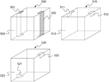
도 6을 참조하면, 본 발명의 하나의 실시예에 따른 전지셀들(500, 510, 520)은, 내부에 전극조립체(도시하지 않음)를 내장하고, 정육면체 형상의 전지케이스(503, 513, 523)를 포함하며, 전지케이스(503, 513, 523)의 외면에는, 전지케이스(503, 513, 523)의 외면 형상에 일체화된 형태로 양극 단자들(501, 511, 521)과 음극 단자들(502, 512, 522)이 각각 형성되어 있다.Referring to FIG. 6, the
양극 단자들(501, 511, 521)과 음극 단자들(502, 512, 522)은 정육면체 형상의 전지케이스(503, 513, 523)의 서로 대면하거나 인접하는 두 개의 변들 상에 변의 형상에 일치하는 사각형 형상으로 형성되어 있고, 인접한 면으로 연장되어 있다. 구체적으로, 하나의 전지셀(500)의 양극 단자(501)와 음극 단자(502)는 서로 대면하는 두 개의 변들 상에 형성되어 있고, 인접한 면으로 연장되어 형성되어 있다. 또 다른 전지셀들(510, 520)은 이러한 양극 단자들(511, 521)과 음극 단자들(512, 522)의 여러 다양한 위치 및 연장 길이를 나타내고 있다.The
도 7을 참조하면, 본 발명의 하나의 실시예에 따른 전지셀들(600, 610, 620)은, 내부에 전극조립체(도시하지 않음)를 내장하고, 정육면체 형상의 전지케이스(603, 613, 623)를 포함하며, 전지케이스(603, 613, 623)의 외면에는, 전지케이스(603, 613, 623)의 외면 형상에 일체화된 형태로 양극 단자들(601, 611, 621)과 음극 단자들(602, 512, 522)이 각각 형성되어 있다.Referring to FIG. 7, the
양극 단자들(601, 611, 621)과 음극 단자들(602, 612, 622)은 정육면체 형상의 전지케이스(603, 613, 623)의 서로 인접하거나 서로 인접하지 않는 두 개의 변들 상에 변의 형상에 일치하는 사각형 형상으로 형성되어 있고, 인접한 면으로 연장되어 있다. 구체적으로, 하나의 전지셀(600)의 양극 단자(601)와 음극 단자(602)는 서로 인접하는 두 개의 변들 상에 형성되어 있고, 인접한 면으로 연장되어 형성되어 있다. 또 다른 전지셀들(610, 620)은 이러한 양극 단자들(611, 621)과 음극 단자들(612, 622)의 여러 다양한 위치 및 연장 길이를 나타내고 있다.The
도 8에는 본 발명의 하나의 실시예에 따른 전지셀의 전극 단자들의 크기관계를 나타내는 투시도들이 도시되어 있다.FIG. 8 is a perspective view illustrating a size relationship of electrode terminals of a battery cell according to an embodiment of the present invention.
도 8을 참조하면, 본 발명에 따른 다면체 전지셀들(140, 150, 160)은 정육면체의 형상이며, 각 변들 또는 각 엣지에 형성된 전극 단자들을 포함하고 있다. 또한, 이들 전극 단자들의 폭(W2)은 전지케이스의 다면체 형상을 이루는 변들의 평균 길이(W1)의 10 내지 50%의 크기로 형성되어 있으며, 이들 전극 단자들의 길이(L2)는 상기 변들의 평균 길이(L1)의 10 내지 100%의 크기로 형성되어 있다.Referring to FIG. 8, the
도 9 및 도 10에는 본 발명의 하나의 실시예에 따른 전지모듈을 구성하는 과정을 나타내는 모식도들이 도시되어 있다.9 and 10 are schematic views illustrating a process of configuring a battery module according to an embodiment of the present invention.
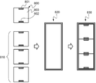
도 9를 참조하면, 본 발명에 따른 다면체 전지셀(700)은, 양극 단자(701) 및 음극 단자(702)가 각각 전지 케이스(703)의 엣지부에 삼각형 형상으로 형성되어 있다. 또한, 이러한 전지셀들(710)은, 양극 단자(701)와 음극 단자(702)가 서로 전기적으로 직렬연결 될 수 있도록 배열(710)된 후, 절연부재(722)가 내장되어 있는 외장 케이스(720)에 수납되어, 하나의 전지모듈(730)을 이룬다.9, in the
구체적으로, 도 9의 전지모듈(730)을 살펴보면, 외장 케이스(720)의 내부에 3개씩 3층 적층 구조로 총 9개의 전지셀들(710, ①, ②, ③, ④, ⑤, ⑥, ⑦, ⑧, ⑨)이 수납되어 있다. 이들 9개의 전지셀들(710)은 ①-②-③-⑥-⑤-④-⑦-⑧-⑨의 순서로 전기적으로 직렬연결되어 있다. 또한, 제 1 층(723)에 수납된 전지셀들(⑦, ⑧, ⑨)과 제 2 층(724)에 수납된 전지셀들(④, ⑤, ⑥)의 개면 및 제2층(724) 수납된 전지셀들(④, ⑤, ⑥)과 제 3 층(725)에 수납된 전지셀들(①, ②, ③)의 개면에 절연부재(722)가 개재되어 있다. 이러한 절연부재(722)는 9개의 전지셀들(710)의 ①-②-③-⑥-⑤-④-⑦-⑧-⑨ 순서의 전기적 직렬연결이 원활이 달성될 수 있도록, 원하지 않는 전기적 단락 (예를 들어, ⑤-⑧, ⑥-⑨, ①-④, ②-⑤ 간의 전기적 단락)을 방지할 수 있다.9, a total of nine
도 10을 참조하면, 본 발명에 따른 다면체 전지셀(800)은, 양극 단자(801) 및 음극 단자(802)가 각각 전지 케이스(803)의 두개의 면에서 대면하는 한 쌍의 변에 사각형 형상으로 형성되어 있다. 또한, 이러한 전지셀들(810)은, 양극 단자(801)와 음극 단자(802)가 서로 전기적으로 직렬연결 될 수 있도록 배열(810)된 후, 외장 케이스(820)에 수납되어, 하나의 전지모듈(830)을 이룬다.
10, a
이상 본 발명의 실시예에 따른 도면을 참조하여 설명하였지만, 본 발명이 속한 분야에서 통상의 지식을 가진 자라면 상기 내용을 바탕으로 본 발명의 범주 내에서 다양한 응용 및 변형을 행하는 것이 가능할 것이다.While the present invention has been described with reference to exemplary embodiments, it is to be understood that the invention is not limited to the disclosed exemplary embodiments.
Claims (24)
상기 전지케이스의 외면에는 다면체 형상에 일체화된 형태로 양극 단자 및 음극 단자가 형성되어 있는 것을 특징으로 하는 다면체 전지셀.An electrode assembly having a separator structure interposed between the positive electrode and the negative electrode and between the positive electrode and the negative electrode is built in the polyhedral battery case,
And a positive electrode terminal and a negative electrode terminal are formed on the outer surface of the battery case in the form of a polyhedron.
상기 다면체 전지셀을 하나 이상 내부에 수납하는 외장 케이스;
전기적으로 연결되지 않은 다면체 전지셀들 간의 전기적 단락을 방지하도록 이들 다면체 전지셀들 사이에 개재되는 절연부재; 및
내부에 수납된 다면체 전지셀들의 전극 단자들과 전기적으로 연결되는 외부 입출력 단자;
를 포함하는 것을 특징으로 하는 전지모듈.A battery module mounted on a module case with at least one polyhedral battery cell according to claim 1 electrically connected,
An outer case for housing at least one of the polyhedral battery cells therein;
An insulating member interposed between the polyhedral battery cells to prevent an electrical short between the polyhedral battery cells that are not electrically connected; And
An external input / output terminal electrically connected to the electrode terminals of the polyhedral battery cells housed therein;
The battery module comprising:
Priority Applications (1)
| Application Number | Priority Date | Filing Date | Title |
|---|---|---|---|
| KR1020130023224A KR101596266B1 (en) | 2013-03-05 | 2013-03-05 | Polyhedral Battery Cell and Battery Module Assembly Employed with the Same |
Applications Claiming Priority (1)
| Application Number | Priority Date | Filing Date | Title |
|---|---|---|---|
| KR1020130023224A KR101596266B1 (en) | 2013-03-05 | 2013-03-05 | Polyhedral Battery Cell and Battery Module Assembly Employed with the Same |
Publications (2)
| Publication Number | Publication Date |
|---|---|
| KR20140109052A true KR20140109052A (en) | 2014-09-15 |
| KR101596266B1 KR101596266B1 (en) | 2016-02-22 |
Family
ID=51755855
Family Applications (1)
| Application Number | Title | Priority Date | Filing Date |
|---|---|---|---|
| KR1020130023224A KR101596266B1 (en) | 2013-03-05 | 2013-03-05 | Polyhedral Battery Cell and Battery Module Assembly Employed with the Same |
Country Status (1)
| Country | Link |
|---|---|
| KR (1) | KR101596266B1 (en) |
Cited By (2)
| Publication number | Priority date | Publication date | Assignee | Title |
|---|---|---|---|---|
| CN115882126A (en) * | 2022-12-14 | 2023-03-31 | 江苏正力新能电池技术有限公司 | Battery case, cylindrical battery and battery module |
| CN115882136A (en) * | 2021-09-29 | 2023-03-31 | 宁德时代新能源科技股份有限公司 | Battery cell, manufacturing method and manufacturing system thereof, battery and electric device |
Citations (4)
| Publication number | Priority date | Publication date | Assignee | Title |
|---|---|---|---|---|
| JP2003045406A (en) * | 2001-07-31 | 2003-02-14 | Matsushita Electric Ind Co Ltd | Sealed battery |
| KR20070033983A (en) * | 2004-05-31 | 2007-03-27 | 닛산 지도우샤 가부시키가이샤 | Battery pack and manufacturing method |
| JP2012064353A (en) * | 2010-09-14 | 2012-03-29 | Sony Corp | Power supply unit |
| JP2012212558A (en) * | 2011-03-31 | 2012-11-01 | Panasonic Corp | Battery module |
-
2013
- 2013-03-05 KR KR1020130023224A patent/KR101596266B1/en active IP Right Grant
Patent Citations (4)
| Publication number | Priority date | Publication date | Assignee | Title |
|---|---|---|---|---|
| JP2003045406A (en) * | 2001-07-31 | 2003-02-14 | Matsushita Electric Ind Co Ltd | Sealed battery |
| KR20070033983A (en) * | 2004-05-31 | 2007-03-27 | 닛산 지도우샤 가부시키가이샤 | Battery pack and manufacturing method |
| JP2012064353A (en) * | 2010-09-14 | 2012-03-29 | Sony Corp | Power supply unit |
| JP2012212558A (en) * | 2011-03-31 | 2012-11-01 | Panasonic Corp | Battery module |
Cited By (2)
| Publication number | Priority date | Publication date | Assignee | Title |
|---|---|---|---|---|
| CN115882136A (en) * | 2021-09-29 | 2023-03-31 | 宁德时代新能源科技股份有限公司 | Battery cell, manufacturing method and manufacturing system thereof, battery and electric device |
| CN115882126A (en) * | 2022-12-14 | 2023-03-31 | 江苏正力新能电池技术有限公司 | Battery case, cylindrical battery and battery module |
Also Published As
| Publication number | Publication date |
|---|---|
| KR101596266B1 (en) | 2016-02-22 |
Similar Documents
| Publication | Publication Date | Title |
|---|---|---|
| JP5889418B2 (en) | Battery module assembly with improved reliability and medium-to-large battery pack including the same | |
| US10062877B2 (en) | Battery module assembly | |
| CN104303332B (en) | Battery cell with step structure | |
| KR101125592B1 (en) | High Capacity Battery Cell of High Life Characteristics and Safety | |
| US20150037664A1 (en) | Battery cell of irregular structure and battery module employed with the same | |
| CN108701793B (en) | Battery pack | |
| KR20070116295A (en) | High capacity battery cell employed with two or more unit cells | |
| KR102055852B1 (en) | Pouch-typed secondary battery comprising modified leads and battery module comprising the same | |
| KR20170098966A (en) | Battery cell | |
| WO2023070677A1 (en) | Battery cell, battery, electrical device, and method and device for manufacturing battery cell | |
| KR101782984B1 (en) | Battery Module Comprising Battery Cells or Unit Modules Having Multi- Directional Connection Structure | |
| US10991985B2 (en) | Secondary battery | |
| KR101521776B1 (en) | Battery Module with Bus-Bar for Changing Position of Output Terminal | |
| KR101596266B1 (en) | Polyhedral Battery Cell and Battery Module Assembly Employed with the Same | |
| WO2023133748A1 (en) | Battery module, battery, electrical device, and method and device for preparing battery | |
| WO2022170492A1 (en) | Battery, power apparatus, and battery manufacturing method and device | |
| KR20230129053A (en) | Battery, electric device, battery manufacturing method and device | |
| KR20150025207A (en) | Lithium Secondary Battery and Battery Pack Comprising The Same | |
| KR101577186B1 (en) | Battery Cell Having Position-changeable Electrode Lead | |
| KR101573224B1 (en) | Battery Module Having Inserted-Typed Temperature Measuring Device | |
| WO2023133747A1 (en) | Battery, electric device, and method and device for preparing battery | |
| CN219393650U (en) | Insulating film, electric core, battery and electric equipment | |
| WO2023155211A1 (en) | Battery, electric device, and battery preparation method and device | |
| KR20140019944A (en) | Battery module having assembling-typed module case | |
| WO2024055236A1 (en) | Battery, electric device, and method for manufacturing battery |
Legal Events
| Date | Code | Title | Description |
|---|---|---|---|
| A201 | Request for examination | ||
| E902 | Notification of reason for refusal | ||
| E701 | Decision to grant or registration of patent right | ||
| GRNT | Written decision to grant | ||
| FPAY | Annual fee payment |
Payment date: 20190116 Year of fee payment: 4 |