KR20140106285A - Portable display device - Google Patents
Portable display device Download PDFInfo
- Publication number
- KR20140106285A KR20140106285A KR1020130020643A KR20130020643A KR20140106285A KR 20140106285 A KR20140106285 A KR 20140106285A KR 1020130020643 A KR1020130020643 A KR 1020130020643A KR 20130020643 A KR20130020643 A KR 20130020643A KR 20140106285 A KR20140106285 A KR 20140106285A
- Authority
- KR
- South Korea
- Prior art keywords
- mode
- display surface
- image display
- display device
- portable display
- Prior art date
Links
Images


Classifications
-
- G—PHYSICS
- G06—COMPUTING; CALCULATING OR COUNTING
- G06F—ELECTRIC DIGITAL DATA PROCESSING
- G06F3/00—Input arrangements for transferring data to be processed into a form capable of being handled by the computer; Output arrangements for transferring data from processing unit to output unit, e.g. interface arrangements
- G06F3/01—Input arrangements or combined input and output arrangements for interaction between user and computer
- G06F3/03—Arrangements for converting the position or the displacement of a member into a coded form
- G06F3/041—Digitisers, e.g. for touch screens or touch pads, characterised by the transducing means
- G06F3/0412—Digitisers structurally integrated in a display
-
- G—PHYSICS
- G06—COMPUTING; CALCULATING OR COUNTING
- G06F—ELECTRIC DIGITAL DATA PROCESSING
- G06F3/00—Input arrangements for transferring data to be processed into a form capable of being handled by the computer; Output arrangements for transferring data from processing unit to output unit, e.g. interface arrangements
- G06F3/01—Input arrangements or combined input and output arrangements for interaction between user and computer
- G06F3/048—Interaction techniques based on graphical user interfaces [GUI]
- G06F3/0481—Interaction techniques based on graphical user interfaces [GUI] based on specific properties of the displayed interaction object or a metaphor-based environment, e.g. interaction with desktop elements like windows or icons, or assisted by a cursor's changing behaviour or appearance
- G06F3/04817—Interaction techniques based on graphical user interfaces [GUI] based on specific properties of the displayed interaction object or a metaphor-based environment, e.g. interaction with desktop elements like windows or icons, or assisted by a cursor's changing behaviour or appearance using icons
-
- G—PHYSICS
- G06—COMPUTING; CALCULATING OR COUNTING
- G06F—ELECTRIC DIGITAL DATA PROCESSING
- G06F3/00—Input arrangements for transferring data to be processed into a form capable of being handled by the computer; Output arrangements for transferring data from processing unit to output unit, e.g. interface arrangements
- G06F3/14—Digital output to display device ; Cooperation and interconnection of the display device with other functional units
Abstract
A portable display device is provided. The portable display device includes a gravity sensor for displaying an image including an icon and including a center area and an edge area and detecting an orientation of the image display surface with respect to gravity, Wherein an angle formed between the image display surface and the gravity direction is closer to a right angle than in the second mode in the first mode and the icon is displayed in the center area in the first mode, In the second mode, the icon is displayed in the edge area.
Description
The present invention relates to a portable display device, and more particularly, to a portable display device including a gravity sensor.
Portable display devices such as a notebook computer, a mobile phone, a smart phone, a portable media player (PMP), and a tablet personal computer (PC) are widely used. The portable display device may include a gravity sensor. The portable display device senses the direction of gravity through the gravity sensor and can detect the position and movement of the portable display device in a three-dimensional space.
A technique for sensing the rotation of a portable display device through a gravity sensor and rotating the image so as to correspond to the rotation of the portable display device has been commonly used in portable display devices, but a technique for improving the usability of a portable display device using other gravity sensors is required.
SUMMARY OF THE INVENTION Accordingly, it is an object of the present invention to provide a portable display device that can improve ease of use by using a gravity sensor.
Another object of the present invention is to provide a portable display device capable of facilitating touch input by using a gravity sensor.
The present invention has been made in view of the above problems, and it is an object of the present invention to provide a method of manufacturing the same.
According to an aspect of the present invention, there is provided a portable display device that displays an image including an icon and includes a center area and an edge area, Wherein an angle formed between the image display surface and the gravity direction in the first mode is closer to a right angle than in the second mode, and the gravity sensor detects the direction of gravity In the first mode, the icon is displayed in the center area, and in the second mode, the icon is displayed in the edge area.
According to another aspect of the present invention, there is provided a portable display device that displays an image including a plurality of icons and includes a center area and an edge area, Wherein an angle formed by the image display surface and the gravity direction in the first mode is closer to a right angle than in the second mode in the first mode and the gravity sensor detects a direction with respect to gravity of the first mode, , The plurality of icons include a first group displayed in the central area in the first mode and the first group is displayed in the edge area in the second mode.
According to another aspect of the present invention, there is provided a portable display device that displays an image including a character input pattern and includes a center area and an edge area, And a gravity sensor for detecting a direction with respect to gravity of the surface, wherein the first mode or the second mode is operated, and in the first mode, the angle formed by the image display surface and the gravity direction is perpendicular to the second mode, A part of the character input pattern is displayed in the center area in the first mode and the character input pattern is displayed in the edge area in the second mode.
According to another aspect of the present invention, there is provided a portable display device including an image display surface for sensing a touch and a gravity sensor for detecting a direction of gravity on the image display surface, 2 mode, wherein an angle formed by the image display surface and the gravity direction is closer to a right angle than in the second mode in the first mode, the image display surface in the first mode does not display an image, In the 2 mode, the image display surface displays an image.
The details of other embodiments are included in the detailed description and drawings.
The embodiments of the present invention have at least the following effects.
That is, the usability of the portable display device can be improved by using the gravity sensor.
In addition, touch input of the portable display device can be facilitated by using the gravity sensor.
The effects according to the present invention are not limited by the contents exemplified above, and more various effects are included in the specification.
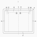
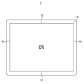
1 is a plan view of a portable display device in a first mode according to an embodiment of the present invention.
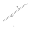
2 is a side view of a portable display device according to an embodiment of the present invention.
3 is a perspective view of a portable display device according to an embodiment of the present invention.
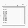
4 is a plan view of a portable display device according to an embodiment of the present invention in a second mode.
5 is a plan view of a portable display device showing movement of an icon when a portable display device according to an embodiment of the present invention is changed from a first mode to a second mode.
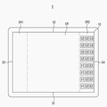
6 is a plan view of a portable display device according to another embodiment of the present invention in a second mode.
7 is a plan view of a portable display device in a second mode according to another embodiment of the present invention.
8 is a plan view of a portable display device according to another embodiment of the present invention in a second mode.
9 is a plan view of a portable display device according to another embodiment of the present invention in a first mode.
10 is a plan view of a portable display device according to still another embodiment of the present invention in a second mode.
11 is a plan view of a portable display device according to another embodiment of the present invention in a first mode.
12 is a plan view of a portable display device according to another embodiment of the present invention in a second mode.
BRIEF DESCRIPTION OF THE DRAWINGS The advantages and features of the present invention, and the manner of achieving them, will be apparent from and elucidated with reference to the embodiments described hereinafter in conjunction with the accompanying drawings. The present invention may, however, be embodied in many different forms and should not be construed as being limited to the embodiments set forth herein. Rather, these embodiments are provided so that this disclosure will be thorough and complete, and will fully convey the scope of the invention to those skilled in the art. Is provided to fully convey the scope of the invention to those skilled in the art, and the invention is only defined by the scope of the claims.
Although the first, second, etc. are used to describe various components, it goes without saying that these components are not limited by these terms. These terms are used only to distinguish one component from another. Therefore, it goes without saying that the first component mentioned below may be the second component within the technical scope of the present invention.
Hereinafter, embodiments of the present invention will be described with reference to the accompanying drawings.
1 is a plan view of a portable display device in a first mode according to an embodiment of the present invention. 1, the
The
The plurality of icons (I1, I2, I3) may be divided into first to third groups. The first group may be a group of icons (I1) arranged in the first edge first edge region (ER1) of the plurality of icons (I1, I2, I3) in the first mode. The second group may be a group of icons (I2) arranged in the first edge central region (CR) of the plurality of icons (I1, I2, I3) in the first mode. The third group may be a group of icons (I3) arranged in the second edge area (ER2) of the plurality of icons (I1, I2, I3) in the first mode. According to some embodiments, the first group or the third group of the first to third groups may not be displayed on the
The
Although not shown, the gravity sensor may be disposed inside the
Referring to Fig. 2, the gravity sensor can detect an angle? 1 that the
Hereinafter, the function of the gravity sensor will be described in more detail with reference to Fig. 3 is a perspective view of a portable display device according to an embodiment of the present invention.
3, the gravity sensor is capable of detecting an angle? 2 formed by the first side S1 with the gravity direction g and an angle? 3 formed by the fourth side S4 and the gravity direction g have. The angle formed by the second side S2 with the gravity direction g is substantially equal to the
Hereinafter, the second mode will be described in more detail with reference to FIG. 4 is a plan view of a portable display device according to an embodiment of the present invention in a second mode. 4 shows an example in which the angle? 2 formed by the first side S1 and the second side S2 with the gravity direction g is smaller than the angle between the third side S3 and the fourth side S4, Is closer to a right angle than the angle [theta] 3, is a diagram relating to the
Referring to FIG. 4, in the second mode, a plurality of icons I1, I2, and I3 may be disposed in the first edge area ER1 and the second edge area ER2. When the plurality of icons I1, I2 and I3 are arranged in the first edge region ER1 and the second edge region ER2, even if the size of the
The sizes of the plurality of icons I1, I2, and I3 may be smaller in the second mode than in the first mode. If the size of the plurality of icons I1, I2 and I3 is smaller in the second mode than in the first mode and the number of the plurality of icons I1, I2 and I3 is large, A plurality of icons I1, I2 and I3 can be arranged in the area ER1 and the second edge area ER2.
Hereinafter, the movement of the icon when changing from the first mode to the second mode will be described with reference to FIG. 5 is a plan view of a portable display device showing movement of an icon when a portable display device according to an embodiment of the present invention is changed from a first mode to a second mode.
5, it is arranged on the left side of the center line CL of the
Hereinafter, another embodiment of the present invention will be described with reference to FIG. 6 is a plan view of a portable display device according to another embodiment of the present invention in a second mode.
The description of the first mode of the
Referring to FIG. 6, a plurality of icons I1, I2, and I3 may be disposed in the first edge area ER1 in the second mode. When a plurality of icons I1, I2 and I3 are arranged in the first edge area ER1 in the second mode, the plurality of icons (I1, I2, I3) I1, I2, I3) can be touched, and the usability of the
Hereinafter, another embodiment of the present invention will be described with reference to FIG. 7 is a plan view of a portable display device in a second mode according to another embodiment of the present invention.
The description of the first mode of the
Referring to FIG. 7, a plurality of icons I1, I2, and I3 may be disposed in the second edge area ER2 in the second mode. When a plurality of icons I1, I2 and I3 are arranged in the second edge area ER2 in the second mode, the plurality of icons (I1, I2, I3) I1, I2, I3) can be touched, and the usability of the
Hereinafter, another embodiment of the present invention will be described with reference to FIG. 8 is a plan view of a portable display device according to another embodiment of the present invention in a second mode.
The description of the first mode of the
Referring to FIG. 8, a plurality of icons I1, I2, and I3 may be disposed in the third edge region ER3 and the fourth edge region ER4 in the second mode. The third edge region ER3 does not include the center of the
Although not shown, according to some embodiments, the
Hereinafter, another embodiment of the present invention will be described with reference to Figs. 9 and 10. Fig. 9 is a plan view of a portable display device according to another embodiment of the present invention in a first mode. 10 is a plan view of a portable display device according to still another embodiment of the present invention in a second mode.
Referring to Fig. 9, in the first mode, an image including a character input pattern (WIP) can be displayed on the
Referring to Fig. 10, in the second mode, the character input pattern WIP may be divided and disposed in the first edge region ER1 and the second edge region ER2. The character input pattern WIP may not be arranged in the central region CR. If the character input pattern WIP is disposed in the first edge region ER1 and the second edge region ER2, the third side S3 and the fourth side S4 The character input pattern WIP can be easily touched while the
Although not shown, according to some embodiments, the character input pattern WIP may be disposed only in the first edge area ER1, or may be disposed only in the second edge area ER2.
Although not shown, according to some other embodiments, in the second mode, the third side S3 and the fourth side S4 are disposed relatively to the upper side or the lower side, and the first side S1 and the second side The angle? 3 formed by the third side S3 and the fourth side S4 with the gravitational direction g is larger than the first side S1 and the second side S2, The character input pattern WIP includes an edge region formed along the first side S1 and / or an edge region formed along the second side S2 when the character input pattern WIP is closer to a right angle than the
Hereinafter, another embodiment of the present invention will be described with reference to FIGS. 11 and 12. FIG. 11 is a plan view of a portable display device according to another embodiment of the present invention in a first mode. 12 is a plan view of a portable display device according to another embodiment of the present invention in a second mode.
Referring to Figs. 11 and 12, the
While the present invention has been described in connection with what is presently considered to be practical exemplary embodiments, it is to be understood that the invention is not limited to the disclosed embodiments, but, on the contrary, You will understand. It is therefore to be understood that the above-described embodiments are illustrative in all aspects and not restrictive.
1: Portable display device 10: Image display surface
CR: center area CL: center line of the image display surface
ER1, ER2, ER3, ER4: first to fourth edge regions
S1, S2, S3, S4: First to fourth sides I1: Icon included in the first group
I2: Icon included in the second group I3: Icon included in the third group
WIP: character input pattern g: gravity direction
Claims (13)
And a gravity sensor for detecting a direction of gravity of the image display surface,
Operating in a first mode or a second mode,
The angle formed by the image display surface and the gravity direction in the first mode is closer to a right angle than in the second mode,
In the first mode, the icon is displayed in the central area,
And the icon is displayed in the edge area in the second mode.
Wherein the size of the icon in the second mode is smaller than that in the first mode.
Wherein the image display surface includes a first side, a second side and a third side and a fourth side opposite to each other,
Wherein the edge region is disposed along the third side or the fourth side,
Wherein an angle formed by the first side or the second side with the gravity direction is closer to a right angle than an angle formed by the third side or the fourth side with the gravity direction.
And a gravity sensor for detecting a direction of gravity of the image display surface,
Operating in a first mode or a second mode,
The angle formed by the image display surface and the gravity direction in the first mode is closer to a right angle than in the second mode,
Wherein the plurality of icons include a first group displayed in the central area in the first mode,
And the first group is displayed in the edge area in the second mode.
Wherein the size of the icon in the second mode is smaller than that in the first mode.
Wherein the image display surface includes a first side, a second side and a third side and a fourth side opposite to each other,
Wherein the edge region is disposed along the third side or the fourth side,
Wherein an angle formed by the first side or the second side with the gravity direction is closer to a right angle than an angle formed by the third side or the fourth side with the gravity direction.
Wherein the image display surface includes a first side, a second side and a third side and a fourth side opposite to each other,
The edge region including a first edge region disposed along the third side and a second edge region disposed along the fourth side,
Wherein an angle formed by the first side or the second side with the gravity direction is closer to a right angle than an angle formed by the third side or the fourth side with the gravity direction.
Wherein each of the icons included in the first group is disposed in the first area when the first mode is close to the third side in the second mode and is located in the second area when the icon is close to the fourth side, A portable display device disposed.
And a gravity sensor for detecting a direction of gravity of the image display surface,
Operating in a first mode or a second mode,
The angle formed by the image display surface and the gravity direction in the first mode is closer to a right angle than in the second mode,
A part of the character input pattern is displayed in the central area in the first mode,
And the character input pattern is displayed in the edge area in the second mode.
Wherein the image display surface includes a first side, a second side and a third side and a fourth side opposite to each other,
Wherein the edge region is disposed along the third side or the fourth side,
Wherein an angle formed by the first side or the second side with the gravity direction is closer to a right angle than an angle formed by the third side or the fourth side with the gravity direction.
Wherein the image display surface includes a first side, a second side and a third side and a fourth side opposite to each other,
The edge region including a first edge region disposed along the third side and a second edge region disposed along the fourth side,
Wherein an angle formed by the first side or the second side with the gravity direction is closer to a right angle than an angle formed by the third side or the fourth side with the gravity direction.
Wherein the character input pattern is divided and displayed in the first edge region and the second edge region in the second mode.
And a gravity sensor for detecting a direction of gravity of the image display surface,
Operating in a first mode or a second mode,
The angle formed by the image display surface and the gravity direction in the first mode is closer to a right angle than in the second mode,
In the first mode, the image display surface does not display an image,
And the image display surface in the second mode displays an image.
Priority Applications (1)
| Application Number | Priority Date | Filing Date | Title |
|---|---|---|---|
| KR1020130020643A KR20140106285A (en) | 2013-02-26 | 2013-02-26 | Portable display device |
Applications Claiming Priority (1)
| Application Number | Priority Date | Filing Date | Title |
|---|---|---|---|
| KR1020130020643A KR20140106285A (en) | 2013-02-26 | 2013-02-26 | Portable display device |
Publications (1)
| Publication Number | Publication Date |
|---|---|
| KR20140106285A true KR20140106285A (en) | 2014-09-03 |
Family
ID=51754799
Family Applications (1)
| Application Number | Title | Priority Date | Filing Date |
|---|---|---|---|
| KR1020130020643A KR20140106285A (en) | 2013-02-26 | 2013-02-26 | Portable display device |
Country Status (1)
| Country | Link |
|---|---|
| KR (1) | KR20140106285A (en) |
Cited By (4)
| Publication number | Priority date | Publication date | Assignee | Title |
|---|---|---|---|---|
| WO2017014475A1 (en) * | 2015-07-17 | 2017-01-26 | 삼성전자 주식회사 | Electronic device and control method therefor |
| US9710161B2 (en) | 2014-12-29 | 2017-07-18 | Samsung Electronics Co., Ltd. | User terminal device and control method thereof |
| CN108874273A (en) * | 2018-06-08 | 2018-11-23 | Oppo广东移动通信有限公司 | Execution method, apparatus, terminal and the storage medium of object run |
| US10409486B2 (en) | 2015-06-02 | 2019-09-10 | Samsung Electronics Co., Ltd. | Electronic device with multi-portion display and control method thereof |
-
2013
- 2013-02-26 KR KR1020130020643A patent/KR20140106285A/en not_active Application Discontinuation
Cited By (8)
| Publication number | Priority date | Publication date | Assignee | Title |
|---|---|---|---|---|
| US9710161B2 (en) | 2014-12-29 | 2017-07-18 | Samsung Electronics Co., Ltd. | User terminal device and control method thereof |
| US10331341B2 (en) | 2014-12-29 | 2019-06-25 | Samsung Electronics Co., Ltd. | User terminal device and control method thereof |
| US10747431B2 (en) | 2014-12-29 | 2020-08-18 | Samsung Electronics Co., Ltd. | User terminal device and control method thereof |
| US20200356265A1 (en) | 2014-12-29 | 2020-11-12 | Samsung Electronics Co., Ltd. | User terminal device and control method thereof |
| US11782595B2 (en) | 2014-12-29 | 2023-10-10 | Samsung Electronics Co., Ltd. | User terminal device and control method thereof |
| US10409486B2 (en) | 2015-06-02 | 2019-09-10 | Samsung Electronics Co., Ltd. | Electronic device with multi-portion display and control method thereof |
| WO2017014475A1 (en) * | 2015-07-17 | 2017-01-26 | 삼성전자 주식회사 | Electronic device and control method therefor |
| CN108874273A (en) * | 2018-06-08 | 2018-11-23 | Oppo广东移动通信有限公司 | Execution method, apparatus, terminal and the storage medium of object run |
Similar Documents
| Publication | Publication Date | Title |
|---|---|---|
| US8963844B2 (en) | Apparatus and method for touch screen user interface for handheld electronic devices part I | |
| JP4743267B2 (en) | Information processing apparatus, information processing method, and program | |
| JP4880304B2 (en) | Information processing apparatus and display method | |
| JP5529700B2 (en) | Information processing apparatus, control method thereof, and program | |
| US20120229399A1 (en) | Electronic device | |
| US9141205B2 (en) | Input display device, control device of input display device, and recording medium | |
| CN105074618A (en) | Foldable display device providing adaptive touch sensitive area and method for controlling the same | |
| JP2012190297A (en) | Electronic apparatus | |
| CN103995668A (en) | Information processing method and electronic device | |
| JP5008707B2 (en) | Input display board and table | |
| JP2012168618A (en) | Electronic apparatus | |
| JP2012008666A (en) | Information processing device and operation input method | |
| KR20140106285A (en) | Portable display device | |
| CN107728910A (en) | Electronic installation, display screen control system and method | |
| KR20120042799A (en) | The bezel of the tablet pc software that is activated | |
| US10585510B2 (en) | Apparatus, systems, and methods for transferring objects between multiple display units | |
| JP2017130158A (en) | Information processing apparatus, display method thereof, and computer-executable program | |
| JP6058118B2 (en) | Operation detection device | |
| TWI515642B (en) | Portable electronic apparatus and method for controlling the same | |
| US20170075453A1 (en) | Terminal and terminal control method | |
| JP5996079B1 (en) | Information processing apparatus, software keyboard display method, and program | |
| TWI534653B (en) | Input device and method of input mode switching thereof | |
| JP5855481B2 (en) | Information processing apparatus, control method thereof, and control program thereof | |
| TWI613569B (en) | Display devices with virtual representations of electronic devices and related method and non-transitory computer-readable storage medium | |
| JP6027182B2 (en) | Electronics |
Legal Events
| Date | Code | Title | Description |
|---|---|---|---|
| WITN | Withdrawal due to no request for examination |