KR20140102258A - Optical guide with superimposed guidance elements and method of manufacture - Google Patents
Optical guide with superimposed guidance elements and method of manufacture Download PDFInfo
- Publication number
- KR20140102258A KR20140102258A KR1020147017575A KR20147017575A KR20140102258A KR 20140102258 A KR20140102258 A KR 20140102258A KR 1020147017575 A KR1020147017575 A KR 1020147017575A KR 20147017575 A KR20147017575 A KR 20147017575A KR 20140102258 A KR20140102258 A KR 20140102258A
- Authority
- KR
- South Korea
- Prior art keywords
- reflective coating
- semi
- guide
- optical
- slide
- Prior art date
Links
Images


Classifications
-
- G—PHYSICS
- G02—OPTICS
- G02B—OPTICAL ELEMENTS, SYSTEMS OR APPARATUS
- G02B6/00—Light guides; Structural details of arrangements comprising light guides and other optical elements, e.g. couplings
- G02B6/24—Coupling light guides
- G02B6/26—Optical coupling means
- G02B6/262—Optical details of coupling light into, or out of, or between fibre ends, e.g. special fibre end shapes or associated optical elements
-
- G—PHYSICS
- G02—OPTICS
- G02B—OPTICAL ELEMENTS, SYSTEMS OR APPARATUS
- G02B6/00—Light guides; Structural details of arrangements comprising light guides and other optical elements, e.g. couplings
-
- G—PHYSICS
- G02—OPTICS
- G02B—OPTICAL ELEMENTS, SYSTEMS OR APPARATUS
- G02B6/00—Light guides; Structural details of arrangements comprising light guides and other optical elements, e.g. couplings
- G02B6/24—Coupling light guides
- G02B6/26—Optical coupling means
- G02B6/34—Optical coupling means utilising prism or grating
-
- G—PHYSICS
- G02—OPTICS
- G02B—OPTICAL ELEMENTS, SYSTEMS OR APPARATUS
- G02B6/00—Light guides; Structural details of arrangements comprising light guides and other optical elements, e.g. couplings
- G02B6/10—Light guides; Structural details of arrangements comprising light guides and other optical elements, e.g. couplings of the optical waveguide type
- G02B6/12—Light guides; Structural details of arrangements comprising light guides and other optical elements, e.g. couplings of the optical waveguide type of the integrated circuit kind
- G02B2006/12166—Manufacturing methods
-
- G—PHYSICS
- G02—OPTICS
- G02B—OPTICAL ELEMENTS, SYSTEMS OR APPARATUS
- G02B6/00—Light guides; Structural details of arrangements comprising light guides and other optical elements, e.g. couplings
- G02B6/0001—Light guides; Structural details of arrangements comprising light guides and other optical elements, e.g. couplings specially adapted for lighting devices or systems
- G02B6/0011—Light guides; Structural details of arrangements comprising light guides and other optical elements, e.g. couplings specially adapted for lighting devices or systems the light guides being planar or of plate-like form
- G02B6/0075—Arrangements of multiple light guides
- G02B6/0076—Stacked arrangements of multiple light guides of the same or different cross-sectional area
-
- Y—GENERAL TAGGING OF NEW TECHNOLOGICAL DEVELOPMENTS; GENERAL TAGGING OF CROSS-SECTIONAL TECHNOLOGIES SPANNING OVER SEVERAL SECTIONS OF THE IPC; TECHNICAL SUBJECTS COVERED BY FORMER USPC CROSS-REFERENCE ART COLLECTIONS [XRACs] AND DIGESTS
- Y10—TECHNICAL SUBJECTS COVERED BY FORMER USPC
- Y10T—TECHNICAL SUBJECTS COVERED BY FORMER US CLASSIFICATION
- Y10T29/00—Metal working
- Y10T29/49—Method of mechanical manufacture
- Y10T29/49826—Assembling or joining
- Y10T29/49885—Assembling or joining with coating before or during assembling
Landscapes
- Physics & Mathematics (AREA)
- General Physics & Mathematics (AREA)
- Optics & Photonics (AREA)
- Optical Couplings Of Light Guides (AREA)
- Light Guides In General And Applications Therefor (AREA)
- Optical Elements Other Than Lenses (AREA)
Abstract
본 발명의 광학 가이드는 휘도 신호를 광학 가이드 내로 주입하도록 의도된 주입 존과 광학 가이드에 의해 이송한 후 휘도 신호를 제공하도록 의도된 추출 존을 포함한다. 이러한 광학 가이드는 겹쳐지는 방식으로, 적어도 2개의 안내 요소(1.1, 1.2)를 포함한다. 주입 존과 추출 존 사이에 있는 존에서는, 안내 요소들이 휘도 신호의 최소 입사각과, 상기 반 반사성 코팅이 분리하는 안내 요소들 중 적어도 하나의 두께에 의존적인, 광학 가이드에서의 휘도 신호의 전파 방향으로의 길이를 지닌 반 반사성 코팅(1.3)에 의해 서로 부분적으로 분리된다.The optical guide of the present invention comprises an extraction zone intended to inject a luminance signal into an optical guide and an extraction zone intended to provide a luminance signal after being conveyed by an optical guide. These optical guides comprise at least two guide elements 1.1, 1.2 in a superposed manner. In the zone between the injection zone and the extraction zone, the guiding elements are arranged in the direction of propagation of the luminance signal in the optical guide, which depends on the minimum incidence angle of the luminance signal and the thickness of at least one of the guiding elements from which the semi- Lt; RTI ID = 0.0 > (1.3). ≪ / RTI >
Description
본 발명은 광 신호를 광학 가이드 내에 주입하도록 의도된 주입 존(zone)과 광학 가이드에 의한 이송 후 광 신호를 제공하도록 의도된 추출 존을 포함하는 광학 가이드에 관한 것이다.The invention relates to an optical guide comprising an injection zone intended to inject an optical signal into an optical guide and an extraction zone intended to provide an optical signal after transport by the optical guide.
통상적으로, 광학 가이드는 주입 존으로부터 추출 존으로의 반사에 의해 광 신호가 이송되는 안내 존을 포함한다. 가장 일반적인 경우는 광 신호가 2개의 평행하고 편평한 슬라이드의 면들 상에서 연속해서 반사되는 경우이다. 광 신호가 주입 존으로부터 추출 존까지 반사되는 광학 가이드의 외부 면들 사이의 거리를 광학 가이드의 두께라고 부른다.Typically, the optical guide includes a guidance zone in which the optical signal is transmitted by reflection from the injection zone to the extraction zone. The most common case is when the optical signal is continuously reflected on the faces of two parallel and flat slides. The distance between the outer surfaces of the optical guide, from which the optical signal is reflected from the injection zone to the extraction zone, is called the thickness of the optical guide.
이송될 이미지 또는 광 신호는 주입 장치 덕분에 광학 가이드 내로 주입된다. 이미지는 광원에 의해 비추어진 LCD(Liquid Cristal Display) 픽셀들의 매트릭스일 수 있는 소스로부터 나오는 광 빔으로 이루어진다. 그러한 이미지는 또한 OLED(Organic Light-Emitting Diode) 픽셀들의 매트릭스일 수 있다. 렌즈들에 기초한 광학 시스템은 이러한 이미지를 시준된 빔의 형태로 투영되어 주입 존을 거쳐 광학 가이드 내로 도입될 수 있게 한다.The image or optical signal to be transferred is injected into the optical guide thanks to the injection device. The image consists of a light beam coming from a source that can be a matrix of LCD (Liquid Crystal Display) pixels illuminated by a light source. Such an image may also be a matrix of OLED (Organic Light-Emitting Diode) pixels. An optical system based on the lenses allows this image to be projected in the form of a collimated beam and introduced into the optical guide through the injection zone.
주입 존의 사이즈는 광학 가이드의 두께에 의존적이고, 광학 가이드 두께 자체는 추출 존과 요구되는 해상도의 사이즈에 의존적이므로, 주입 장치의 전반적인 사이즈 또한 그러하다.The size of the injection zone is dependent on the thickness of the optical guide, and since the optical guide thickness itself depends on the size of the extraction zone and the required resolution, so is the overall size of the injection device.
주어진 사이즈를 가지는 추출 존에 관해, 주입 장치의 전체 사이즈를 감소시키는 것을 허용하는 해결책을 제공하는 것이 바람직한데, 이는 주입 존의 사이즈를 줄이는 것을 의미한다.For an extraction zone having a given size, it is desirable to provide a solution that allows to reduce the overall size of the injection device, which means to reduce the size of the injection zone.
추출 존을 거쳐 제공된 광 신호에서 감지된 휘도가 균일할 수 있게 하는 해결책을 제공하는 것이 특히 바람직하다.It is particularly preferred to provide a solution that allows the sensed brightness in the provided optical signal via the extraction zone to be uniform.
간단하게 구현하고 경비가 적게 되는 해결책을 제공하는 것이 특히 바람직하다.It is particularly desirable to provide a solution that is simple to implement and low in cost.
본 발명은 광학 가이드 내로 광 신호를 주입하도록 의도된 주입 존과 광학 가이드에 의한 이송 후 광 신호를 제공하도록 의도된 추출 존을 포함하는 광학 가이드에 관한 것이다. 이러한 광학 가이드는 그것이 겹쳐지는 방식으로 적어도 2개의 안내 요소를 포함하도록 되어 있다. 이러한 광학 가이드는 또한 주입 존과 추출 존 사이에 있는 존에서, 안내 요소들이 광 신호의 최소 입사각과 반 반사성(semi-reflective) 코팅이 분리하는 안내 요소들 중 적어도 하나의 두께에 의존적인, 광학 가이드에서의 광 신호의 전파 방향으로 길이를 가진 반 반사성 코팅에 의해 서로 부분적으로 분리되도록 되어 있다.The invention relates to an optical guide comprising an injection zone intended to inject optical signals into an optical guide and an extraction zone intended to provide an optical signal after transfer by the optical guide. Such an optical guide is adapted to include at least two guide elements in such a way that they overlap. This optical guide is also characterized in that, in the zone between the injection zone and the extraction zone, the guiding elements are dependent on the thickness of at least one of the guiding elements from which the minimum incident angle of the optical signal and the semi-reflective coating separate, Is partially separated from each other by a semi-reflective coating having a length in the direction of propagation of the optical signal in the light-emitting layer.
따라서, 주어진 사이즈를 가지는 추출 존에 관해, 주입 존이 감소되고 따라서 주입 존을 거쳐 광 신호를 제공하는 역할을 하는 주입 장치의 전체 사이즈가 감소한다.Thus, for an extraction zone having a given size, the injection zone is reduced, thus reducing the overall size of the injection device, which serves to provide the optical signal through the injection zone.
특별한 일 실시예에 따르면, 반 반사성 코팅의 길이는 그것이 상기 반 반사성 코팅 상의 광 신호의 적어도 2회의 리바운드(rebound)를 허용하도록 정해진다.According to one particular embodiment, the length of the semi-reflective coating is such that it allows at least two rebounds of the optical signal on the semi-reflective coating.
따라서, 추출 존을 거쳐 제공된 광 신호에서 감지된 휘도의 균일성이 증가하는데, 반 반사성 코팅의 반사율과 투과율이 같지 않고, 반 반사성 코팅의 흡수가 그러한 투과율과 반사율에 대해 무시 가능할 때(5% 미만의 흡수율) 그러하다.Thus, when the reflectivity and transmittance of the semi-reflective coating are not equal and the absorption of the semi-reflective coating is negligible (less than 5%) for such transmittance and reflectivity, the uniformity of the sensed brightness in the optical signal provided through the extraction zone increases. Water absorption rate).
특별한 일 실시예에 따르면, 반 반사성 코팅의 반사율 및 투과율은 실질적으로 같다.According to one particular embodiment, the reflectance and transmittance of the semi-reflective coating are substantially equal.
따라서, 추출 존을 거쳐 제공된 광 신호에서 감지된 휘도의 균일성이 증가한다.Thus, the uniformity of the detected brightness in the optical signal provided through the extraction zone increases.
특별한 일 실시예에 따르면, 광학 가이드는 겹쳐지는 방식으로, 안내 요소들의 연속물을 형성하는 적어도 3개의 안내 요소를 포함하고, 반 반사성 코팅이 후속하는 안내 요소로부터 각각의 안내 요소를 부분적으로 분리한다. 게다가, 광학 가이드는 반 반사성 코팅에 의해 투과된 광 신호가 중간 반사 없이 후속하는 반 반사성 코팅에 의해 투과되도록 배치된다.According to a particular embodiment, the optical guides comprise at least three guiding elements forming a series of guiding elements in a superposed manner, partly separating each guiding element from the guiding elements following the semi-reflective coating. In addition, the optical guide is arranged such that the optical signal transmitted by the semi-reflective coating is transmitted by the subsequent semi-reflective coating without intermediate reflection.
따라서, 주입 장치의 전체 사이즈에 있어서의 감소가 증가된다. 또한, 동일한 재료와 동일한 두께로 제조된 슬라이드(slide)들과 같은 안내 요소들을 사용하는 것이 가능함으로써, 광학 가이드의 제조 비용을 단순화시키고 감소시킨다.Thus, the reduction in the overall size of the injection apparatus is increased. It is also possible to use guide elements such as slides made of the same material and the same thickness, thereby simplifying and reducing the manufacturing cost of the optical guide.
특별한 일 실시예에 따르면, 각각의 반 반사성 코팅은 안내 요소들의 연속물에서 그것의 위치에 의존적인 반사율을 가지고, 이 경우 반 반사성 코팅은 그것의 반사율보다 강한 반사율을 가지는 또 다른 반 반사성 코팅에 의해 투과된 광 신호를 투과시킨다.According to a particular embodiment, each semi-reflective coating has a reflectivity dependent on its position in the series of guiding elements, in which case the semi-reflective coating is transmitted by another semi-reflective coating having a reflectivity that is stronger than its reflectivity Thereby transmitting the optical signal.
따라서, 추출 존에 의해 제공된 광 신호에서 감지된 휘도의 균일성이 증가된다.Thus, the uniformity of the sensed brightness in the optical signal provided by the extraction zone is increased.
특별한 일 실시예에 따르면, 안내 요소들은 동일한 두께를 가진다.According to a particular embodiment, the guiding elements have the same thickness.
따라서, 광학 가이드의 제조는 간단하고 비용이 감소한다.Thus, the manufacture of the optical guide is simple and the cost is reduced.
특별한 일 실시예에 따르면, 안내 요소들은 동일한 재료로 이루어진다.According to a particular embodiment, the guiding elements are made of the same material.
따라서, 광학 가이드의 제조 있어서의 간단함과 비용 면에서의 감소가 증가된다.Therefore, the simplicity and cost reduction in the manufacture of the optical guide is increased.
특별한 일 실시예에 따르면, 안내 요소들은 상이한 재료들로부터 제조되고, 그것들의 두께는 그것들의 굴절률들과 광 신호의 최소 입사각에 의존적이다.According to a particular embodiment, the guiding elements are made of different materials, the thickness of which depends on their refractive indices and the minimum incident angle of the optical signal.
따라서, 광학 가이드의 구현 상황에서 그것의 용도에 따라 안내 요소들 각각에 관한 재료의 선택을 행하는 것이 가능하다. 예를 들면, 주입 장치의 고정을 가능하게 하기 위한 구조를 또한 포함하는 어떤 안내 요소는 이러한 강제 사항에 맞는 기계적 특성들을 제공하는 재료로 이루어질 수 있는데 반해, 각각의 다른 안내 요소는 더 낮은 기계적 스트레스(stress)들을 견디는 재료로 제조될 수 있어, 비용이 덜 든다. 따라서, 광학 가이드의 제조에 있어서의 유연성이 증가된다.Therefore, it is possible to make a selection of the material for each of the guide elements according to its use in the state of implementation of the optical guide. For example, any guiding element that also includes a structure to enable fixation of the injection device can be made of a material that provides mechanical properties meeting these requirements, while each of the other guiding elements has a lower mechanical stress can be made of a material that withstands stresses, which is less costly. Thus, the flexibility in manufacturing the optical guide is increased.
특별한 일 실시예에 따르면, 광학 가이드는 안내 요소들의 연속물을 형성하는 적어도 3개의 안내 요소, 후속하는 안내 요소로부터 각각의 안내 요소를 부분적으로 분리하는 반 반사성 코팅을 겹쳐지는 방식으로 포함한다. 게다가, 이러한 광학 가이드는 하나의 안내 요소와 후속하는 안내 요소 사이의 하나의 반 반사성 코팅에 의해 투과된 광 신호가 반사 없이, 상기 후속하는 안내 요소로 들어가지 않도록 배치된다.According to a particular embodiment, the optical guide comprises at least three guide elements forming a series of guide elements, in a superposed manner, a semi-reflective coating partially separating the respective guide elements from the following guide elements. In addition, such an optical guide is arranged so that the optical signal transmitted by one semi-reflective coating between one guide element and the subsequent guide element does not enter the subsequent guide element without reflection.
따라서, 주입 장치의 전반적인 사이즈에 있어서의 감소가 증가된다.Thus, the reduction in the overall size of the injection device is increased.
특별한 일 실시예에 따르면, 광학 가이드는 안내 요소들의 연속물과, 후속하는 안내 요소로부터 각각의 안내 요소를 부분적으로 분리하는 반 반사성 코팅을 형성하도록 겹쳐지는 방식으로 배치된 적어도 3개의 안내 요소로 이루어진 그룹을 포함한다. 이러한 광학 가이드는 또한 하나의 반 반사성 코팅에 의한 반사 없이 투과된 광 신호가 후속하는 반 반사성 코팅에 의해 투과되도록 배치된다. 이러한 광학 가이드는 또한 적어도 하나의 다른 안내 요소, 안내 요소들의 상기 그룹으로부터 이러한 다른 안내 요소를 부분적으로 분리하는 반 반사성 코팅을 포함하도록 정해진다. 이러한 광학 가이드는 또한 안내 요소들의 그룹 중 하나의 반 반사성 코팅에 의해 투과된 광 신호가 반사 없이 상이 다른 안내 요소에 들어가지 않도록 배치된다.According to a particular embodiment, the optical guide comprises a series of guiding elements and a group of at least three guiding elements arranged in a superposed manner to form a semi-reflective coating partially separating the guiding elements from the following guiding elements . This optical guide is also arranged so that the transmitted optical signal, without reflection by a single semi-reflective coating, is transmitted by a subsequent semi-reflective coating. This optical guide is also defined to include at least one other guiding element, a semi-reflective coating that partially separates these other guiding elements from the group of guiding elements. This optical guide is also arranged such that the optical signal transmitted by the semi-reflective coating of one of the group of guiding elements does not enter the other guiding element without reflection.
특별한 일 실시예에 따르면, 하나의 안내 요소와 후속하는 안내 요소 사이의 하나의 반 반사성 코팅에 의해 투과된 광 신호가 반사 없이 후속하는 안내 요소에 들어가지 않도록 하기 위해 상기 안내 요소와 상기 후속하는 안내 요소는 반사성 코팅에 의해 부분적으로 분리된다.According to a particular embodiment, in order to prevent the optical signal transmitted by one semi-reflective coating between one guiding element and the following guiding element from entering the subsequent guiding element without reflection, the guiding element and the subsequent guiding element The elements are partially separated by a reflective coating.
따라서, 반 반사성 코팅과 반사성 코팅의 적층을 관리함으로써, 사이즈가 동일한 슬라이드들과 같은 안내 요소들을 사용하는 것이 가능하고, 그 제조가 단순화된다.Thus, by managing the stacking of the semi-reflective coating and the reflective coating, it is possible to use guide elements, such as slides of the same size, and its manufacture is simplified.
특별한 일 실시예에 따르면, 하나의 안내 요소와 후속하는 안내 요소 사이의 하나의 반 반사성 코팅에 의해 투과된 광 신호가 반사 없이 후속하는 안내 요소에 들어가지 않도록 하기 위해, 상기 후속하는 안내 요소는 상기 반 반사성 코팅에 의해 광 신호가 투과되는 광학 가이드의 존에 존재하지 않는다.According to a particular embodiment, in order to prevent the optical signal transmitted by one semi-reflective coating between one guiding element and the subsequent guiding element from entering the subsequent guiding element without reflection, It does not exist in the zone of the optical guide through which the optical signal is transmitted by the semi-reflective coating.
따라서, 재료 비용이 감소한다.Therefore, the material cost is reduced.
본 발명은 또한 광학 가이드 내로 광 신호를 주입하도록 의도된 주입 존과 광학 가이드에 의한 이송 후 광 신호를 제공하도록 의도된 추출 구역을 포함하는 광학 가이드를 제조하는 방법에 관한 것이다. 이러한 제조 방법은 적어도 2개의 안내 요소를 얻는 단계, 주입 존과 추출 존 사이에 있는 존에서 하나를 제외한 각각의 안내 요소에 반 반사성 코팅을 적층하는 단계로서, 상기 반 반사성 코팅은 광 신호의 최소 입사각과, 상기 반 반사성 코팅이 분리하도록 의도되는 안내 요소들 중 적어도 하나의 두께에 따라, 광학 가이드에서 광 신호가 전파하는 방향으로 길이를 가지는, 적층 단계; 및 각각의 반 반사성 코팅이 2개의 안내 요소를 분리하도록 겹쳐지는 방식으로 안내 요소들을 조립하는 단계를 포함한다.The invention also relates to a method of manufacturing an optical guide comprising an injection zone intended to inject an optical signal into an optical guide and an extraction zone intended to provide an optical signal after transport by the optical guide. This manufacturing method comprises the steps of obtaining at least two guiding elements, laminating a semi-reflective coating on each guiding element except one in the zone between the injection zone and the extraction zone, the semi-reflective coating having a minimum incident angle And a length in a direction in which the optical signal propagates in the optical guide, depending on the thickness of at least one of the guide elements intended to separate the semi-reflective coating. And assembling the guide elements in such a way that each semi-reflective coating overlaps to separate the two guide elements.
전술한 본 발명의 특징들은, 다른 것들과 함께, 실시예의 후속하는 설명을 읽음으로써 좀더 명확히 드러나게 되고, 상기 설명은 첨부 도면과 관련하여 주어지는 것이다.BRIEF DESCRIPTION OF THE DRAWINGS The foregoing features of the present invention, along with others, will be more clearly apparent from a reading of the following description of an embodiment, and the description is given with reference to the accompanying drawings.
도 1은 본 발명에 따른 제 1 광학 가이드의 일부를 개략적으로 예시하는 도면.
도 2는 본 발명에 따른 제 2 광학 가이드의 일부를 개략적으로 예시하는 도면.
도 3은 본 발명에 따른 제 3 광학 가이드의 일부를 개략적으로 예시하는 도면.
도 4는 본 발명에 따른 제 4 광학 가이드의 일부를 개략적으로 예시하는 도면.
도 5는 본 발명에 따른 광학 가이드의 제조 방법을 개략적으로 예시하는 도면.
도 6의 (a) 내지 (g)는 분사 장치의 위치 선정에 관한 광학 가이드의 배치들을 개략적으로 예시하는 도면들.1 schematically illustrates a part of a first optical guide according to the present invention;
2 schematically illustrates a part of a second optical guide according to the present invention;
Fig. 3 schematically illustrates a part of a third optical guide according to the present invention; Fig.
Fig. 4 schematically illustrates a part of a fourth optical guide according to the present invention; Fig.
5 is a view schematically illustrating a method of manufacturing an optical guide according to the present invention.
Figures 6 (a) - (g) schematically illustrate the arrangement of optical guides with respect to the positioning of the injectors.
주입 장치의 전체 사이즈를 줄이는 것을 가능하게 하기 위해, 주입 존과 추출 존 사이에 있는 존에서 반 반사성 코팅에 의해 부분적으로 분리된 적어도 2개의 안내 요소를 광학 가이드가 포함하는 것이 제안된다. 이러한 반 반사성 코팅은 단일(single)-슬라이드 광학 가이드에 대해 동공의 사이즈가 증가하는 것을 허용하는데, 이는 고정된 동공 치수의 경우 주입 장치의 전체 사이즈를 감소시키는 것을 의미한다. 광학 전파를 허용하면서, 단일 물체에서 함께 안내 요소들과 만나기 위해서는 간극성(interstitial) 재료를 사용하는 것이 필요하다. 이는 그렇게 조립된 안내 요소들 사이의 임의의 공기 공간이 회피되어야 하기 때문이고, 이들은 총 내부 반사들의 출현을 야기하며, 이러한 조립의 목적은 반 반사성 코팅들에 의해 부분적으로 분리된 다양한 안내 요소들에서 광이 전파하는 것을 허용하는 것이다. 이러한 간극성 재료는 예를 들면 안내 요소들을 함께 붙잡기 위해 아교(glue)일 수 있다. 이러한 간극성 재료는 심지어 광 신호의 최소 입사각(αmin)에 대해서도 임의의 총 내부 반사를 방지하는 굴절률을 가지게 된다. 안내 요소들의 재료와 간극성 재료의 굴절률 차이에 의해 야기된 반사들은 그러한 굴절률 차이를 0.1보다 크지 않게 확실히 함으로써 유리하게 최소화된다. 그러므로 사용자에 의해 구별될 투영된 이미지의 세부 사항들의 사이즈는 약 0.03°이고, 안내 요소들 사이의 패럴렐리즘(parallelism)은 약 0.01°이다.In order to make it possible to reduce the overall size of the injection device it is proposed that the optical guide comprises at least two guide elements which are partly separated by a semi-reflective coating in the zone between the injection zone and the extraction zone. This semi-reflective coating allows the pupil size to increase with respect to the single-slide optical guide, which means to reduce the overall size of the injection device for fixed pupil dimensions. It is necessary to use an interstitial material to meet the guiding elements together in a single object while allowing optical propagation. This is because any air space between the assembled guiding elements must be avoided and they cause the appearance of total internal reflections, and the purpose of such assembly is to prevent Allowing light to propagate. Such a polar material may be, for example, glue to hold the guide elements together. Such a polar material also has a refractive index that prevents any total internal reflection, even for the minimum incident angle (? Min ) of the optical signal. The reflections caused by the refractive index difference of the material of the guiding elements and the interstitial material are advantageously minimized by ensuring that such refractive index difference is not greater than 0.1. Therefore, the size of the details of the projected image to be distinguished by the user is about 0.03 degrees, and the parallelism between the guide elements is about 0.01 degrees.
후속하는 설명에서, 안내 요소들은 평행한 면들을 지닌 슬라이드들이다. 본 발명의 상황에서는, 특히 동일한 면 상에 병치된 방식으로, 주입 존과 추출 존을 포함하는 안내 요소와 같은, 다른 안내 요소들이 사용될 수 있다. 이러한 경우, 안내 요소들을 분리하는 반 반사성 코팅은 추출 전에 광 신호의 리바운드를 허용한다.In the following description, the guiding elements are slides with parallel sides. In the context of the present invention, other guiding elements may be used, such as guiding elements comprising an injection zone and an extraction zone, in particular in a juxtaposition on the same plane. In this case, a semi-reflective coating separating the guiding elements allows rebound of the optical signal before extraction.
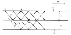
본 발명에 따른 제 1 광학 가이드의 한 부분이, 광학 가이드에서 광 신호의 전파 방향(D)으로의 단면도에 따라 도 1에 개략적으로 예시되어 있다.A part of the first optical guide according to the present invention is schematically illustrated in Fig. 1 according to a cross-sectional view in the direction of propagation (D) of the optical signal in the optical guide.
제 1 광학 가이드는 광 가이드 내로 광 신호를 주입하도록 의도된 주입 장치(미도시)와, 예를 들면 사용자의 눈에 광학 가이드에 의해 이송된 후 광 신호를 제공하도록 의도된 추출 장치(미도시)를 포함한다.The first optical guide may include an injection device (not shown) intended to inject optical signals into the optical guide and an extraction device (not shown) intended to provide optical signals after being conveyed by an optical guide, for example, .
제 1 광학 가이드는 두께가 e1인 제 1 슬라이드(1.1)와 두께가 e2인 제 2 슬라이드를 포함한다. 제 1 슬라이드(1.1)와 제 2 슬라이드(1.2)는 겹쳐져 있고, 그것들의 면은 평행하다. 광 신호는 슬라이드들의 상기 면들 상에서의 반사에 의해 광학 가이드에서 전파한다.A first optical guide and a second slide having a thickness e 1 of the first slide (1.1) with a thickness of e 2. The first slide (1.1) and the second slide (1.2) overlap, and their surfaces are parallel. The optical signal propagates in the optical guide by reflection on the surfaces of the slides.
추출 장치의 배치는 제 1 슬라이드(1.1)의 면이나 제 2 슬라이드(1.2)의 면 상의 광 신호를 위한 추출 존(미도시)을 규정한다.The arrangement of the extraction device defines an extraction zone (not shown) for the optical signal on the surface of the first slide (1.1) or the surface of the second slide (1.2).
주입 장치의 배치는 제 1 슬라이드(1.1)의 제 1 면 상의 광 신호를 위한 주입 존을 규정한다. 이러한 주입 존은 도 1에서의 세그먼트[J,K]에 의해 나타내어진다. 광 신호의 광선들은 제 1 슬라이드(1.1)의 면들에 대해 각도(α)에서 제 1 슬라이드(1.1)로 주입되고, 이는 이들 면의 법선에 대한 각도(β)에 대응한다. 즉, β=π/2 - α이다.The arrangement of the injection device defines an injection zone for the optical signal on the first side of the first slide (1.1). This injection zone is represented by the segment [J, K] in Fig. The light rays of the optical signal are injected into the first slide 1.1 at an angle? Relative to the faces of the first slide 1.1, which corresponds to the angle? With respect to the normal of these faces. That is, β = π / 2 - α.
광 신호의 광선들의 최소 입사각(αmin)은 도 1에 도시된 것이다. 최소 입사각(αmin)으로 제 1 슬라이드(1.1)의 제 2 면 상으로의 포인트(J)의 투영은 포인트(L)로 나타내어진다. 포인트(K)의 투영은 포인트(M)에 의해 나타내어진다.The minimum incident angle [alpha] min of the light rays of the optical signal is shown in Fig. The projection of point J onto the second side of the first slide 1.1 at the minimum incident angle alpha min is indicated by the point L. [ The projection of point K is represented by point M.
제 1 슬라이드(1.1)와 제 2 슬라이드(1.2)는 반 반사성 코팅(1.3)에 의해 부분적으로 분리되고, 이는 이러한 반 반사성 코팅(1.3)이 주입 존과 추출 존 사이에 있는 광학 가이드의 존에 배치됨을 의미한다. 따라서, 제 1 슬라이드(1.1) 내로 주입된 광 신호의 광선들은 제 1 슬라이드(1.1)에서의 그것들의 전파를 계속하기 위해 반 반사성 코팅(1)에 의해 부분적으로 반사되고, 제 2 슬라이드(1.2)에서의 그것들의 전파를 계속하기 위해 반 반사성 코팅(1.3)에 의해 부분적으로 투과된다. 따라서, 광 신호의 일부는 제 1 슬라이드(1.1)에 남아 있고, 또 다른 부분은 제 2 슬라이드(1.2)로 들어간다. 반 반사성 코팅(1.3)은 적어도 도 1에서 세그먼트[L,M]에 의해 나타낸 면 위에서 연장한다.The first slide (1.1) and the second slide (1.2) are partly separated by a semi-reflective coating (1.3), which is placed in the zone of the optical guide where this semi-reflective coating (1.3) is between the injection zone and the extraction zone . The rays of the optical signal injected into the first slide 1.1 are therefore partly reflected by the antireflective coating 1 to continue their propagation in the first slide 1.1, Is partially transmitted by the antireflective coating (1.3) to continue their propagation. Thus, a portion of the optical signal remains on the first slide (1.1) and another portion enters the second slide (1.2). The semi-reflective coating 1.3 extends at least over the plane represented by segment [L, M] in FIG.
도 1에서는, 주입된 광선들이 실선으로 된 화살표들에 의해 나타내어져 있고, 마찬가지로 이들 주입된 광선들의 반 반사성 코팅(1.3)에 의한 반사로부터 생긴 광선들과 이들 주입된 광선들의 반 반사성 코팅(1.3)에 의한 투과로부터 생긴 광선들은 점선으로 된 화살표들로 나타내어져 있다.In Figure 1, the injected rays are represented by solid arrows, and likewise the rays from the reflection of these injected rays by the antireflective coating 1.3 and the rays of these injected rays, The light rays resulting from the transmission by the light source are indicated by dashed arrows.
광 신호가 제 1 슬라이드(1.1)를 채우기 위해서는, 제 1 슬라이드(1.1)의 면들 상의 광 신호의 임프린트(imprint)는 광학 가이드에서의 광 신호의 전파 방향(D)으로 길이인 l 1을 가지는데, 이 경우In order for the optical signal to fill the first slide 1.1 the imprint of the optical signal on the faces of the first slide 1.1 has a length l 1 in the propagation direction D of the optical signal in the optical guide , in this case
l 1 = ![]()
![]()
광 신호가 제 1 슬라이드(1.2)를 채우기 위해서는, 제 1 슬라이드(1.2)의 면들 상의 광 신호의 임프린트는 광학 가이드에서의 광 신호의 전파 방향(D)으로 길이인 l 2를 가지는데, 이 경우 제 1 슬라이드(1.1)와 제 2 슬라이드(1.2)가 동일한 재료로 구성될 때In order for the optical signal to fill the first slide (1.2), the imprint of the optical signal on the faces of the first slide (1.2) has a length l 2 in the propagation direction (D) of the optical signal in the optical guide, When the first slide (1.1) and the second slide (1.2) are constructed of the same material
l 2 = ![]()
![]()
전체 광학 가이드에 대한 광 신호의 임프린트(l tot)는 이러한 상황 하에서,Imprint (l tot) of the optical signal for the overall optical guide Under such circumstances,
l tot ≥ ![]()
![]()
를 만족하고, 여기서 l은 광학 가이드에서 광 신호의 전파 방향(D)으로의 반 반사성 코팅(1.3)의 길이[L, M]를 나타낸다. 이럴 경우 이러한 길이(l)는, Where l represents the length [L, M] of the semi-reflective coating 1.3 in the direction of propagation of the optical signal D in the optical guide. In this case, the length ( l )
l ≥ ![]()
![]()
이 된다..
따라서, 길이(l)는 제 2 슬라이드(1.2)의 두께(e2)와 광 신호의 최소 입사각(αmin)의 함수로서 정해진다.Thus, the length (l) is determined as a function of the minimum angle of incidence (α min) of the thickness (e 2) and the light signal of the second slide (1.2).
특별한 일 실시예에서, 광 신호가 광학 가이드를 좀더 균일하게 채우기 위해서는, 제 1 슬라이드(1.1)의 두께(e1)가 제 2 슬라이드(1.2)의 두께(e2)와 같다. 따라서, 사용자가 인식한 휘도는 좀더 균일하게 된다.In a particular embodiment, the optical signal is to fill the optical guide in more uniform, the thickness (e 1) of the first slide (1.1) equal to the thickness (e 2) of the second slide (1.2). Thus, the brightness perceived by the user becomes more uniform.
제 1 슬라이드(1.1)와 제 2 슬라이드(1.2)가 상이한 재료들로 만들어질 때, 그것들의 두께비는When the first slide (1.1) and the second slide (1.2) are made of different materials, their thickness ratio
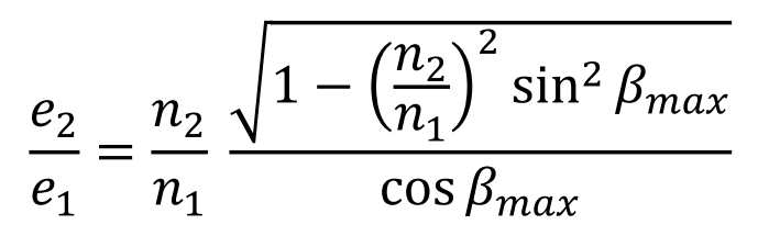
가 되고, 이 경우 n1은 제 1 슬라이드(1.1)의 굴절률을 나타내고, n2는 제 2 슬라이드(1.2)의 굴절률을 나타내며, βmax는 각도(α)가 값(αmin)을 취할 때, 각도(β)의 값에 대응한다. 따라서, 슬라이드들이 상이한 재료들로부터 제조될 때, 그것들의 두께는 그것들의 굴절률과 광 신호의 최소 입사각에 의존적이다.Where n 1 represents the index of refraction of the first slide 1.1 and n 2 represents the index of refraction of the second slide 1.2 and β max is the index of refraction of the second slide 1.2 when the angle α takes the value α min , Corresponds to the value of the angle beta. Thus, when the slides are made from different materials, their thickness depends on their refractive index and minimum incident angle of the optical signal.
예를 들면, 제 1 슬라이드(1.1)를 폴리메틸 메타크릴레이트(PMMA)로 제작하고, 제 2 슬라이드(1.2)를 폴리카보네이트로 제작함으로써, 최소 입사각(αmin)은 23.5°와 같고, 약 1.16인 비(e2/e1)가 얻어진다.For example, when the first slide 1.1 is made of polymethylmethacrylate (PMMA) and the second slide 1.2 is made of polycarbonate, the minimum angle of incidence α min is equal to 23.5 ° and about 1.16 (E 2 / e 1 ) is obtained.
휘도의 균일성은 반 반사 코팅(1.3)이 실질적으로 그것이 반사하는 만큼이나 투과시킬 때 증가될 수 있고, 이는 최대 반 반사 코팅(1.3)의 투과율(t)과 반사율(r) 사이의 20%의 차이가 존재함을 의미한다. 바람직한 일 실시예에서, 이러한 반 반사 코팅(1.3)의 투과율(t)과 반사율(r)은 같다. 이후, 도 2와 도 3에 관련하여 설명되는 광학 가이드들에 대해서도 동일하게 적용된다.The uniformity of the brightness can be increased when the antireflective coating 1.3 substantially transmits as it is reflected since there is a difference of 20% between the transmittance t of the full antireflective coating 1.3 and the reflectivity r It means that it exists. In one preferred embodiment, the transmittance (t) and reflectance (r) of this antireflective coating 1.3 are the same. Hereinafter, the same applies to the optical guides described with reference to FIGS. 2 and 3. FIG.
t + r = 1 - a라는 사실이 상기되고, 이 경우 a는 반 반사 코팅(1.3)에 의한 광 신호의 흡수를 나타낸다.The fact that t + r = 1 - a is recalled, where a represents the absorption of the optical signal by the antireflective coating 1.3.
특별한 일 실시예에서, 길이(l)는 광학 가이드로 주입된 광 신호가 반 반사 코팅(1.3) 상에서 적어도 2회의 리바운드를 수행할 수 있도록 정해진다. 이는 반 반사 코팅(1.3)의 투과율(t)과 반사율(r) 사이의 임의의 차이 효과를 감쇄시킨다. 이후 도 2, 도 3, 및 도 4에 관련하여 설명된 광학 가이드들에 대해서도 동일하게 적용된다.In a particular embodiment, the length l is such that the optical signal injected into the optical guide is capable of performing at least two rebounds on the antireflective coating 1.3. This attenuates the effect of any difference between the transmittance (t) and the reflectivity (r) of the antireflective coating (1.3). The same applies to the optical guides described with reference to Figs. 2, 3, and 4 hereinafter.
바람직한 일 실시예에서, 길이(l)는 광학 가이드로 주입된 광 신호가 반 반사성 코팅(1.3) 상에서 2회의 리바운드를 수행할 수 있도록 정해진다.In a preferred embodiment, the length l is such that the optical signal injected into the optical guide is capable of performing two rebounds on the antireflective coating 1.3.
따라서, 예를 들어 제 1 슬라이드(1.1)의 두께와 제 2 슬라이드(1.2)의 두께가 2㎜와 같고, 최소 입사각(αmin)이 23.5°와 같게 하면, 광학 가이드에서 광 신호의 전파 방향으로 길이가 9.2㎜인 임프린트가 얻어진다. 이는 반 반사성 코팅(1.3)의 최소 길이가 9.2㎜임을 의미한다. 이 길이는 사용자에 의해 인지된 휘도의 균일성을 개선하기 위해, 반 반사성 코팅(1.3)에서 주입된 광 신호가 2회의 리바운드를 수행할 수 있게 하기 위해 18.4㎜로 확립될 수 있다. 18.4㎜의 그러한 길이는 안경(glasses)에서의 광학 가이드의 통합에 적합한데, 이 경우 주입 장치와 추출 장치 사이의 거리는 약 50㎜이다.Therefore, when the thickness of the first slide (1.1) and the thickness of the second slide (1.2) are equal to 2 mm and the minimum incident angle (? Min ) is equal to 23.5 degrees, An imprint having a length of 9.2 mm is obtained. This means that the minimum length of the semi-reflective coating 1.3 is 9.2 mm. This length can be established as 18.4 mm to allow the optical signal injected in the semi-reflective coating 1.3 to perform two rebounds in order to improve the uniformity of the brightness perceived by the user. Such a length of 18.4 mm is suitable for the integration of optical guides in glasses, where the distance between the injection device and the extraction device is about 50 mm.
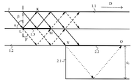
본 발명에 따른 제 2 광학 가이드의 부분은, 광학 가이드에서의 광 신호의 전파 방향(D)으로의 단면도인 도 2에 개략적으로 예시되어 있다.The portion of the second optical guide according to the present invention is schematically illustrated in Fig. 2, which is a sectional view in the propagation direction (D) of the optical signal in the optical guide.
제 2 광학 가이드는 제 1 슬라이드(1.1), 제 2 슬라이드(1.2), 반 반사성 코팅(1.3), 및 두께가 e3인 제 3 슬라이드(2.1)를 포함한다. 제 1 슬라이드(1.1), 제 2 슬라이드(1.2), 및 제 3 슬라이드(2.1)는 겹쳐져 있고, 그것들의 면들은 평행하다. 광 신호는 슬라이드들의 상기 면들 상에서의 반사들에 의해 광학 가이드에서 전파한다. 도 1에서의 제 1 광학 가이드의 상황에서처럼, 제 1 슬라이드(1.1)와 제 2 슬라이드(1.2)는 반 반사성 코팅(1.3)에 의해 분리된다.The second optical guide comprises a first slide (1.1), the second slide (1.2), anti-reflective coating (1.3), and a third slide (2.1) having a thickness e 3. The first slide (1.1), the second slide (1.2), and the third slide (2.1) overlap and their sides are parallel. The optical signal propagates in the optical guide by the reflections on the surfaces of the slides. As in the situation of the first optical guide in Fig. 1, the first slide 1.1 and the second slide 1.2 are separated by a semi-reflective coating 1.3.
제 2 광학 가이드의 상황에서, 제 1 슬라이드(1.1), 제 2 슬라이드(1.2), 및 제 3 슬라이드(2.1)는 동일한 재료로 구성되고, 제 1 슬라이드(1.1)의 두께(e1)는 제 2 슬라이드(1.2)의 두께(e2)와 같고, 제 3 슬라이드(2.1)의 두께(e3)는 두께(e1)와 두께(e2)의 합과 같다. 제 1 슬라이드(1.1), 제 2 슬라이드(1.2), 및 제 3 슬라이드(2.1)가 다른 재료들로 구성될 때에는, 그것들의 두께가 그것들의 굴절률들과 광 빔의 최소 입사각에 의존적이다. 제 3 슬라이드(2.1) 상에 겹쳐지도록 또 다른 슬라이드가 광학 가이드에 추가될 때에는, 이러한 다른 슬라이드는 두께들(e1, e2, 및 e3)의 합과 같은 두께를 가진다. 다른 슬라이드들이 추가되는 경우에도 마찬가지 방식으로 이루어진다.In the situation of the second optical guide, the first slide 1.1, the second slide 1.2 and the third slide 2.1 are made of the same material and the thickness e 1 of the first slide 1.1 is equal to the thickness (e 2) of the second slide (1.2), the thickness (e 3) of the third slide (2.1) is equal to the sum of the thickness (e 1) and thickness (e 2). When the first slide (1.1), the second slide (1.2), and the third slide (2.1) are made of different materials, their thickness depends on their refractive indices and the minimum incident angle of the light beam. When another slide is added to the optical guide so that it overlaps on the third slide (2.1), this other slide has the same thickness as the sum of the thicknesses (e 1 , e 2 , and e 3 ). The same is true when other slides are added.
제 2 슬라이드(1.2)와 제 3 슬라이드(2.1)는 반 반사성 코팅(1.3)과 유사한 반 반사성 코팅(2.2)에 의해 부분적으로 분리된다. 제 3 슬라이드(2.1)와 반 반사성 코팅(2.2)의 배치는, 반 반사성 코팅(1.3)에 의해 투과된 광선들이 제 2 슬라이드(1.2)의 반대측 면에 의해 완전히 반사되도록 정해진다. 제 1 슬라이드(1.1)로 주입되고 제 2 슬라이드(1.2)에서 전파된 광 신호의 다른 광선들과 제 2 슬라이드(1.2)에서 반사된 광선들은, 제 3 슬라이드(2.10에서의 그것들의 전파를 계속하기 위해, 반 반사성 코팅(2.2)에 의해 부분적으로 투과된다. 따라서, 광 신호의 일부는 제 1 슬라이드(1.1)에 남아 있고, 또 다른 부분은 제 2 슬라이드(1.2)로 들어간 다음 그 안에서 반사되고, 또 다른 부분이 제 3 슬라이드(2.1)로 들어가서 그 안에서 반사된다. 도 2에는, 주입된 광선들이 실선으로 된 화살표로 나타나 있고, 반 반사성 코팅(1.3)에 의해 이들 주입된 광선들의 반사로부터 생기는 광선들이 그러한 것처럼, 반 반사성 코팅(1.3)에 의해 이들 주입된 광선들의 투과로부터 생기는 광선들은 긴 점선들로 된 화살표들로 나타내져 있으며, 반 반사성 코팅(2.3)에 의한 투과로부터 생긴 광선들은 짧은 점선으로 된 화살표들로 나타내져 있다.The second slide (1.2) and the third slide (2.1) are partly separated by a semi-reflective coating (2.2) similar to the semi-reflective coating (1.3). The arrangement of the third slide (2.1) and the semi-reflective coating (2.2) is such that the rays transmitted by the semi-reflective coating (1.3) are completely reflected by the opposite side of the second slide (1.2). The other rays of the optical signal injected into the first slide (1.1) and propagated in the second slide (1.2) and the rays reflected at the second slide (1.2) continue to propagate in the third slide A part of the optical signal remains on the first slide 1.1 and the other part enters the second slide 1.2 and is then reflected in it, Another part enters the third slide 2.1 and is reflected therein. In figure 2, the injected rays are indicated by solid arrows and the rays from the reflection of these injected rays by the antireflective coating 1.3 As such, the rays resulting from the transmission of these injected rays by the antireflective coating 1.3 are shown by the arrows with long dashed lines, and from the transmission by the semi-reflective coating (2.3) Long beam are shown turned into the short dashed arrow.
반 반사성 코팅(2.2)은 도 2에서 세그먼트[N,O]에 의해 나타낸 존 위에서 적어도 연장하고, 제 3 슬라이드(2.1)의 엣지는 포인트(N)에 있으며, 포인트(N)는 이러한 제 2 슬라이드에서의 최소 입사각으로 제 2 슬라이드(1.2)의 제 2 면 상으로의 포인트(M)의 투영에 대응하고, 이는 슬라이드들이 동일한 재료로 구성될 때의 각도(αmin)를 의미한다. 제 3 슬라이드(2.1)는 상기 반 반사성 코팅에 의해 광 신호가 투과되는 광학 가이드의 존에 존재하지 않는다. 반 반사성 코팅(2.2)은 포인트(N)로부터 연장하고, 광학 가이드에서의 광 신호의 전파 방향(D)으로의 반 반사성 코팅(2.2)의 길이[N,O]는 l3로 표현되며The semi-reflective coating 2.2 extends at least above the zone indicated by the segment [N, O] in Fig. 2, the edge of the third slide 2.1 is at point N, Corresponds to the projection of the point M onto the second side of the second slide 1.2 with a minimum incidence angle at the second side of the second slide 1.2, which means the angle alpha min when the slides are constructed of the same material. The third slide (2.1) is not present in the zone of the optical guide through which the optical signal is transmitted by the semi-reflective coating. The antireflective coating 2.2 extends from point N and the length [N, O] of the antireflective coating 2.2 in the propagation direction D of the optical signal in the optical guide is represented by l 3
l3 ≥![]()
![]()
가 된다..
따라서, 반 반사성 코팅(2.2)의 길이[N,O]는 제 3 슬라이드(2.1)의 두께(e3)와, 광 신호의 최소 입사각(αmin)의 함수로서 정해진다.Accordingly, the length of the anti-reflective coating (2.2) [N, O] is determined as a function of the minimum angle of incidence (α min) of the thickness (e 3) of the third slide (2.1), the optical signal.
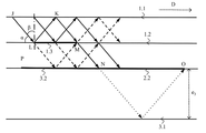
본 발명에 따른 제 3 광학 가이드의 일부가 광학 가이드에서의 광 신호의 전파 방향(D)으로의 단면도인 도 3에 개략적으로 예시되어 있다. 이 제 3 광학 가이드는 도 2와 관련하여 위에서 설명된 제 2 광학 가이드의 일 변형예이다.A part of the third optical guide according to the present invention is schematically illustrated in Fig. 3, which is a sectional view in the propagation direction D of the optical signal in the optical guide. This third optical guide is a modification of the second optical guide described above with reference to Fig.
제 3 광학 가이드는 제 1 슬라이드(1.1), 제 2 슬라이드(1.2), 및 두께(e3)를 가진 제 3 슬라이드(3.1), 그리고 반 반사성 코팅들(1.3, 2.2)을 포함한다. 이러한 반 반사성 코팅(2.2)은 도 2와 관련하여 위에서 제시된 바와 같이, 세그먼트[N,O] 상에 배치된다.A third optical guide comprises a first slide (1.1), with the second slide (1.2), and a third slide (3.1), and anti-reflective coating having a thickness (e 3) (1.3, 2.2 ). This semi-reflective coating 2.2 is disposed on the segment [N, O], as shown above in connection with FIG.
도 2에 관련하여 위에서 설명된 제 2 광학 가이드와는 달리, 제 3 슬라이드(3.1)의 엣지는 포인트(N)에 위치하고 있지 않다. 반 투과성 코팅(1.3)에 의해 투과된 광선들이 제 2 슬라이드(1.2)의 반대측 면에 의해 완전히 반사되도록 하기 위해, 제 2 슬라이드(1.2)와 제 3 슬라이드(3.1)가 완전 반사 코팅(3.2)에 의해 부분적으로 분리된다. 이러한 완전 반사 코팅(3.2)은 세그먼트[P,N]에 의해 도 3에 나타낸 표면 위에서 연장한다. 이 존은 세그먼트[P',N]에 의해 도 3에서 단면도로 나타내어지는 표면 위에서 적어도 연장하고, 이 경우 P'은 광 신호의 최대 입사각(αmax)에서 제 2 슬라이드(1.2)의 반대측 면 상에서의 포인트(L)의 투영이다.Unlike the second optical guide described above with reference to FIG. 2, the edge of the third slide 3.1 is not located at point N. The second slide 1.2 and the third slide 3.1 are placed on the fully reflective coating 3.2 so that the light rays transmitted by the semi-transparent coating 1.3 are completely reflected by the opposite side of the second slide 1.2 Lt; / RTI > This fully reflective coating 3.2 extends over the surface shown in Fig. 3 by a segment [P, N]. This zone at least extends on the surface indicated by the section [P ', N] on the cross-sectional view in Figure 3, where P' is the maximum angle of incidence of the optical signal ( max ) on the opposite side of the second slide (L).
제 2 광학 가이드와 제 3 광학 가이드는 겹쳐진, 슬라이드들의 연속물을 형성하는 적어도 3개의 슬라이드를 포함하고, 이 경우 반 반사성 코팅이 슬라이드들의 연속물에서 후속하는 슬라이드로부터 각각의 슬라이드를 부분적으로 분리한다. 이들 광학 가이드는 하나의 슬라이드와 후속하는 슬라이드 사이의 반 반사성 코팅에 의해 투과된 광 신호가 반사 없이 후속하는 슬라이드에 들어가지 않도록 배치된다.The second optical guide and the third optical guide comprise at least three slides overlapping, forming a series of slides, wherein the semi-reflective coating partially separates each slide from the subsequent slides in the series of slides. These optical guides are arranged such that the optical signal transmitted by the semi-reflective coating between one slide and the subsequent slide does not enter the subsequent slide without reflection.
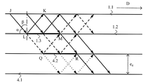
본 발명에 따른 제 4 광학 가이드의 부분이 광학 가이드에서 광 신호의 전파 방향(D)으로의 단면도인 도 4에 개략적으로 예시되어 있다.A portion of the fourth optical guide according to the present invention is schematically illustrated in Fig. 4, which is a cross-sectional view in the optical guide of the optical signal in the propagation direction (D).
제 2 광학 가이드는 제 1 슬라이드(1.1), 제 2 슬라이드(1.2), 반 반사성 코팅(1.3), 및 두께가 e4인 제 3 슬라이드(4.1)를 포함한다. 제 1 슬라이드(1.1), 제 2 슬라이드(1.2), 및 제 3 슬라이드(4.1)가 겹쳐지고 그것들의 면이 평행하다. 광 신호는 슬라이드들의 상기 면들 상의 반사에 의해 광학 가이드에서 전파한다. 도 1에서의 제 1 광학 가이드의 상황에서처럼, 제 1 슬라이드(1.1)와 제 2 슬라이드(1.2)는 반 반사성 코팅(1.3)에 의해 분리된다.The second optical guide comprises a first slide (1.1), the second slide (1.2), anti-reflective coating (1.3), and a third slide (4.1) having a thickness e 4. The first slide (1.1), the second slide (1.2), and the third slide (4.1) are superimposed and their faces are parallel. The optical signal propagates in the optical guide by reflection on the surfaces of the slides. As in the situation of the first optical guide in Fig. 1, the first slide 1.1 and the second slide 1.2 are separated by a semi-reflective coating 1.3.
제 2 슬라이드(1.2)와 제 3 슬라이드(4.1)는 반 반사성 코팅(4.2)에 의해 분리된다. 이 반 반사성 코팅(4.2)은 도 4에서 세그먼트[Q,R]에 의해 나타내어지는 존 위에서 연장한다. 포인트(Q)는 슬라이드들이 동일한 재료로 구성될 때, 제 2 슬라이드(1.2)의 최소 입사각, 즉 각도(αmin)에서 제 2 슬라이드(1.2)의 제 2 면 상에서의 포인트(L)의 투영(projection)에 대응한다. 포인트(R)는 이러한 제 2 슬라이드(1.2)에서의 최소 입사각에서 제 2 슬라이드(1.2)의 제 2 면 상의 포인트(M)의 투영에 대응한다.The second slide (1.2) and the third slide (4.1) are separated by a semi-reflective coating (4.2). This semi-reflective coating 4.2 extends over the zone represented by segment [Q, R] in FIG. Point Q is the projection of point L on the second side of the second slide 1.2 at the minimum incidence angle of the second slide 1.2, i.e. the angle alpha min , when the slides are constructed of the same material projection. The point R corresponds to the projection of the point M on the second side of the second slide 1.2 at the minimum incidence angle in this second slide 1.2.
제 4 광학 가이드는 겹쳐지는 방식으로, 슬라이드들의 연속물을 형성하는 적어도 3개의 슬라이드를 포함하고, 이 경우 반 반사성 코팅이 후속하는 슬라이드로부터 각각의 슬라이드를 부분적으로 분리시킨다. 이러한 광학 가이드는, 반 반사성 코팅에 의한 중간 반사 없이 투과된 광 신호가 후속하는 반 반사성 코팅에 의해 투과되도록 배치된다. 그러므로, 2개의 반 반사성 코팅 사이에는 반사가 존재하지 않는다.The fourth optical guide comprises at least three slides forming a series of slides in an overlapping manner, in which case the semi-reflective coating partially separates each slide from the subsequent slides. This optical guide is arranged so that the optical signal transmitted without intermediate reflection by the semi-reflective coating is transmitted by the subsequent semi-reflective coating. Therefore, there is no reflection between the two semi-reflective coatings.
반 반사성 코팅(1.3)이 그것의 반사율(r)의 2배와 같은 투과율(t)을 가질 때, 즉 이는 t=2/3이고 r=1/3인 경우로 반 반사성 코팅(1.3)에 의한 흡수를 무시함을 의미하고, 반 반사성 코팅(4.2)이 그것의 반사율(r)과 같은 투과율(t)을 가질 때, 즉 이는 t=r=1/2인 경우로 반 반사성 코팅(4.2)에 의한 흡수를 무시함을 의미할 때, 휘도의 균일성이 증가될 수 있다.When the antireflective coating 1.3 has a transmittance t equal to twice its reflectivity r, that is, when t = 2/3 and r = 1/3, Reflective coating 4.2 means that when the semi-reflective coating 4.2 has a transmittance t equal to its reflectance r, i.e. t = r = 1/2, , The uniformity of the luminance can be increased.
각각의 반 반사성 코팅이 슬라이드들의 연속물에서 그것의 위치에 의존적인 반사율을 가지고, 이 경우 하나의 반 반사성 코팅은 이러한 반 반사성 코팅의 반사율보다 높은 반사율을 가지는 또 다른 반 반사성 코팅에 의해 투과된 광 신호를 투과시킨다.Each of the semi-reflective coatings has a reflectivity that is dependent on its position in a series of slides, where one semi-reflective coating is a light signal transmitted by another semi-reflective coating having a reflectivity higher than that of this < .
즉, 광 신호에 의해 처음으로 부딪힌 반 반사성 코팅으로부터 시작하는 슬라이드들의 연속물에서의 위치에서의 반 반사성 코팅이 인덱스(k)를 가지고, k=l,...,n-l일 때(여기서 n은 슬라이드의 개수), 이러한 반 반사성 코팅은 That is, when a semi-reflective coating at a position in a series of slides starting from a semi-reflective coating hit first by an optical signal has an index k and k = l, ..., nl, The number of < RTI ID = 0.0 >
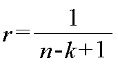
인 반사율을 가진다.Respectively.
도 4와 도 2 또는 도 3에 관련하여 위에서 개시된 원리들을 결합하는 것이 가능하다. 이 경우, 광학 가이드는 슬라이드들의 연속물을 형성하기 위해 겹쳐진 방식으로 배치된 적어도 3개의 슬라이드의 그룹을 포함하고, 이 경우 반 반사성 코팅이 후속하는 슬라이드로부터 각각의 슬라이드를 부분적으로 분리시키며, 반 반사성 코팅에 의한 반사 없이 투과된 광 신호가 후속하는 반 반사성 코팅에 의해 투과되도록 광학 가이드가 배치된다. 이 그룹은 도 4에 관련하여 위에서 제시된 배치에 대응한다. 광학 가이드는 또한 적어도 하나의 다른 슬라이드를 포함하고, 이 경우 반 반사성 코팅은 슬라이드들의 그룹으로부터 이러한 다른 슬라이드를 부분적으로 분리시키며, 슬라이드들의 그룹의 반 반사성 코팅에 의해 투과된 광 신호가 반사 없이 상기 다른 슬라이드에 들어가지 않도록 광학 가이드가 배치된다. 이러한 배치는 도 2 또는 도 3에 관련하여 위에서 제시된 것에 대응한다.It is possible to combine the principles disclosed above with respect to Fig. 4 and Fig. 2 or Fig. In this case, the optical guide comprises a group of at least three slides arranged in an overlapping manner to form a series of slides, in which case the semi-reflective coating partly separates each slide from the subsequent slide, The optical guide is disposed such that the transmitted optical signal is reflected by the subsequent semi-reflective coating. This group corresponds to the arrangement presented above with respect to FIG. The optical guide also includes at least one other slide, wherein the semi-reflective coating partially separates these other slides from the group of slides, and the optical signal transmitted by the semi-reflective coating of the group of slides is reflected by the other An optical guide is disposed so as not to enter the slide. This arrangement corresponds to that presented above with reference to FIG. 2 or FIG.
위에서 제시된 제 1, 제 2, 제 3 또는 제 4 광학 가이드는 바람직하게는 안경(glasses)에서 통합되도록 의도된다. 주입 장치의 전체 사이즈에 있어서의 감소는 또한 주입 장치의 업스트림에 사용된 렌즈들이 전체 사이즈에 있어서의 감소를 수반하고, 따라서 이들 안경의 사이즈를 전체적으로 감소시킨다. 따라서, 이들 안경을 착용하는 사용자의 편안함이 증대된다.The first, second, third or fourth optical guides presented above are preferably intended to be integrated in glasses. The reduction in the overall size of the infusion set also results in a reduction in the total size of the lenses used in the upstream of the infusion set, thus reducing the overall size of these glasses. Thus, the comfort of the wearer of these glasses is increased.
광 신호는 세그먼트[J,K]에 의해 나타내어진 주입 존에 의해 직접 주입될 수 있음이 주목되어야 한다. 예를 들면, 이러한 주입 장치는 제 1 슬라이드(1.1)의 외부 면 상에 장착된 면이고, 이는 제 2 슬라이드(1.2)에 맞닿아 위치하고 있지 않은 제 1 슬라이드(1.1)의 면을 의미한다.It should be noted that the optical signal can be injected directly by the injection zone represented by the segment [J, K]. For example, this injection device is a face mounted on the outer surface of the first slide 1.1, which means the face of the first slide 1.1 which is not in contact with the second slide 1.2.
광 신호는 세그먼트[J,K]에 의해 나타내어진 주입 존에 의해 간접적으로 주입될 수 있다는 점이 주목되어야 한다. 예를 들면, 광 신호는 슬라이드 중 하나 또는 다른 것의 면들 중 적어도 하나 상에서의 반사를 사전에 겪을 수 있다.It should be noted that the optical signal can be injected indirectly by the injection zone represented by the segment [J, K]. For example, the optical signal may experience a reflection on at least one of the faces of one of the slides or the other.
따라서, 주입 장치의 위치 선정에 대한 광학 가이드의 다양한 배치가 도 6의 (a) 내지 (g)에 개략적으로 도시되어 있다.Accordingly, various arrangements of the optical guides for positioning the injection device are schematically shown in Figures 6 (a) - (g).
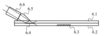
도 6의 (a) 내지 (f)는 겹쳐진 방식으로 장착된 제 1 평행면(parallel-face) 슬라이드(6.1)와 제 2 평행면 슬라이드(6.2)를 포함하는 광학 가이드를 개략적으로 예시한다. 이러한 광학 가이드는 또한 추출 존(6.3)을 포함한다. 광학 가이드는 또한 도 1에 관련하여 앞서 설명된 것처럼 배치된 반 반사성 코팅(6.4)을 포함한다.Figures 6 (a) - (f) schematically illustrate an optical guide comprising a first parallel-face slide 6.1 and a second parallel slide 6.2 mounted in an overlapping manner. This optical guide also includes an extraction zone 6.3. The optical guide also includes a semi-reflective coating (6.4) disposed as described above with respect to FIG.
도 6의 (a)에 나타낸 그림에서, 광학 가이드는 시준된 빔의 형태로 이미지의 투영을 가능하게 하는 렌즈들의 세트(6.6)와 제 1 슬라이드(6.1) 상에 장착된 주입 피스(piece)(6.5) 면을 포함하는 주입 장치와 관련되어 사용된다. 렌즈들의 세트(6.6)는 주입 피스(6.5)로 시준된 빔을 투과시키고, 이러한 주입 피스(6.5)는 투과된 빔을 제 1 슬라이드(6.1)로 주입한다. 그 다음 주입된 빔은 부분적으로 반사되고, 이미 설명된 바와 같이, 반 반사성 코팅(6.4)에 의해 부분적으로 투과된다.In the illustration shown in Figure 6 (a), the optical guide comprises a set of lenses (6.6) enabling the projection of the image in the form of a collimated beam and an injection piece mounted on the first slide (6.1) 6.5) < / RTI > The set of lenses 6.6 transmit the collimated beam to the injection piece 6.5 and this injection piece 6.5 injects the transmitted beam into the first slide 6.1. The injected beam is then partially reflected and partially transmitted by the semi-reflective coating 6.4, as previously described.
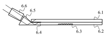
도 6의 (b)에서의 그림에서는, 광학 가이드가 제 2 슬라이드(6.2) 상에 장착된 주입 피스(6.5) 표면을 포함하는 주입 장치와 관련되어 사용된다. 주입 피스(6.5)는 제 1 슬라이드(6.1)에 맞닿아 장착되는 제 2 슬라이드(6.2)의 면 상에 장착된다. 그러므로, 제 1 슬라이드(6.1)는 주입 피스(6.5)가 제 2 슬라이드(6.2)에 맞닿아 놓여질 수 있게 하는 오목부를 포함한다. 주입 장치는 또한 렌즈들의 세트(6.6)를 포함하고, 이러한 렌즈들의 세트는 시준된 빔의 형태로 이미지를 투영하는 것을 가능하게 한다. 렌즈들의 세트(6.6)는 시준된 빔을 주입 피스(6.5)에 투과시키고, 이러한 주입 피스(6.5)는 투과된 빔을 제 2 슬라이드(6.2) 내로 주입한다. 그 다음 주입된 빔은 반 반사성 코팅(6.4)에 부딪히기 전에 제 2 슬라이드(6.2)의 반대측 면에 의해 반사된다.In the illustration in Figure 6 (b), an optical guide is used in connection with an injection device comprising an injection piece (6.5) surface mounted on a second slide (6.2). The injection piece 6.5 is mounted on the face of the second slide 6.2 which is mounted against the first slide 6.1. Thus, the first slide 6.1 includes a recess that allows the injection piece 6.5 to be brought into abutment with the second slide 6.2. The injection device also includes a set of lenses (6.6), which enables projection of an image in the form of a collimated beam. A set of lenses 6.6 transmit the collimated beam to the injection piece 6.5 and this injection piece 6.5 injects the transmitted beam into the second slide 6.2. The injected beam is then reflected by the opposite side of the second slide (6.2) before it hits the semi-reflective coating (6.4).
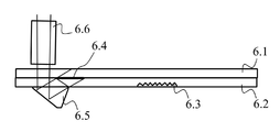
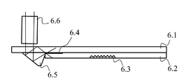
도 6의 (c)에서의 그림에서는, 광학 가이드가 제 2 슬라이드(6.2) 상의 돌기부에 대응하는 주입 피스(6.5)를 포함하는 주입 장치와 관련되어 사용된다. 이러한 돌기부는 제 1 슬라이드(6.1)가 제 2 슬라이드(6.2) 상에 장착되는 측과 동일한 측 상에서 연장한다. 주입 장치는 또한 렌즈들의 세트(6.6)를 포함하는데, 이러한 세트는 시준된 빔의 형태로 이미지를 투영하는 것을 가능하게 한다. 렌즈들의 세트(6.6)는 시준된 빔을 주입 피스(6.5)에 투과시키고, 이러한 주입 피스는 투과된 빔을 제 2 슬라이드(6.2) 내로 주입한다. 그러면 주입된 빔은 반 반사성 코팅(6.4)과 부딪히기 전에 제 2 슬라이드(6.2)의 반대측 면에 의해 반사된다.6 (c), an optical guide is used in connection with an injection device comprising an injection piece 6.5 corresponding to the projection on the second slide 6.2. These protrusions extend on the same side as the side on which the first slide 6.1 is mounted on the second slide 6.2. The injection device also includes a set of lenses (6.6), which enable to project an image in the form of a collimated beam. A set of lenses (6.6) transmits the collimated beam to the injection piece (6.5), which injects the transmitted beam into the second slide (6.2). The injected beam is then reflected by the opposite side of the second slide (6.2) before it hits the semi-reflective coating (6.4).
도 6의 (d)에서의 그림에서는, 광학 가이드가 제 2 슬라이드(6.2) 상에 장착된 주입 피스(6.5) 면을 포함하는 주입 장치와 관련되어 사용된다. 주입 피스(6.5)는 제 1 슬라이드(6.1)에 맞닿아 장착되는 것과 반대측에 있는 제 2 슬라이드(6.2)의 면 상에 장착된다. 주입 장치는 또한 렌즈들의 세트(6.6)를 포함하고, 이러한 세트는 시준된 빔의 형태로 이미지를 투영할 수 있다. 렌즈들의 세트(6.6)는 제 2 슬라이드(6.2)에 맞닿아 장착되는 것과 반대측에 있는 제 1 슬라이드(6.1)의 면 측 상에 장착된다. 렌즈들의 세트(6.6)는 제 1 슬라이드(6.1)와 제 2 슬라이드(6.2)를 거쳐, 주입 피스(6.5)에 시준된 빔을 투과시킨다. 따라서, 시준된 빔은 제 1 슬라이드(6.1)와 제 2 슬라이드(6.2)의 면들에 수직이 되게 제 1 슬라이드(6.1)와 제 2 슬라이드(6.2)를 통과한다. 시준된 빔은 주입 피스(6.5)의 면에 맞닿아 반사되고, 반사에 의해 제 1 슬라이드(6.1) 내로 주입된다. 그러면 주입된 빔은 부분적으로 반사되고, 이미 설명된 바와 같이, 반 반사성 코팅(6.4)에 의해 부분적으로 투과된다.6 (d), an optical guide is used in connection with an injection device comprising an injection piece (6.5) face mounted on a second slide 6.2. The injection piece 6.5 is mounted on the face of the second slide 6.2 on the side opposite to that which is abutted against the first slide 6.1. The injection device also includes a set of lenses (6.6), which can project an image in the form of a collimated beam. A set of lenses (6.6) is mounted on the side of the first slide (6.1) on the opposite side of the second slide (6.2) against which it is mounted. A set of lenses 6.6 transmit the collimated beam through the first slide 6.1 and the second slide 6.2 to the injection piece 6.5. Thus, the collimated beam passes through the first slide 6.1 and the second slide 6.2 perpendicular to the faces of the first slide 6.1 and the second slide 6.2. The collimated beam is reflected by being in contact with the face of the injection piece 6.5 and injected into the first slide 6.1 by reflection. The injected beam is then partially reflected and partially transmitted by the semi-reflective coating (6.4), as already explained.
도 6의 (e)에서의 그림에서는, 광학 가이드가 제 1 슬라이드(6.1) 상에 장착된 주입 피스(6.5) 면을 포함하는 주입 장치와 관련되어 사용된다. 주입 피스(6.5)는 제 2 슬라이드(6.2)에 맞닿아 장착되는 제 1 슬라이드(6.1)의 면 상에 장착된다. 따라서, 제 2 슬라이드(6.2)는 주입 피스(6.5)가 제 1 슬라이드(6.1)에 맞닿아 배치되는 것을 가능하게 하는 오목부를 포함한다. 주입 장치는 또한 렌즈들의 세트(6.6)를 포함하고, 이러한 세트는 시준된 빔의 형태로 이미지를 투영하는 것을 가능하게 한다. 렌즈들의 세트(6.6)는 제 2 슬라이드(6.2)에 맞닿아 장착되는 것의 반대측에 있는 제 1 슬라이드(6.1)의 면 측에 장착된다. 렌즈들의 세트(6.6)는 제 1 슬라이드(6.1)를 거쳐 주입 피스(6.5)로 시준된 빔을 투과시킨다. 그렇게 시준된 빔은 제 1 슬라이드(6.1)의 면들에 수직이 되게 제 1 슬라이드(6.1)를 통과한다. 시준된 빔은 주입 피스(6.5)의 면에 맞닿아 반사되고, 제 1 슬라이드(6.1) 내로 반사에 의해 주입된다. 그러면 주입된 빔은 반 반사성 코팅(6.4)에 부딪히기 전에 제 1 슬라이드(6.1)의 반대측 면에 의해 반사된다.6 (e), an optical guide is used in connection with an injection device comprising an injection piece (6.5) face mounted on the first slide 6.1. The injection piece 6.5 is mounted on the face of the first slide 6.1 to be mounted against the second slide 6.2. Thus, the second slide 6.2 includes a recess allowing the injection piece 6.5 to be placed against the first slide 6.1. The injection device also includes a set of lenses 6.6, which enables projection of an image in the form of a collimated beam. A set of lenses (6.6) is mounted on the side of the first slide (6.1) opposite the side to which it is abutted against the second slide (6.2). A set of lenses (6.6) transmit the collimated beam through the first slide (6.1) to the injection piece (6.5). The collimated beam thus passes through the first slide 6.1 perpendicular to the faces of the first slide 6.1. The collimated beam is reflected by being in contact with the face of the injection piece 6.5 and injected by reflection into the first slide 6.1. The injected beam is then reflected by the opposite side of the first slide (6.1) before it impinges on the semi-reflective coating (6.4).
도 6의 (f)에서의 그림에서는, 광학 가이드가 제 1 슬라이드(6.1) 상의 돌기부에 대응하는 주입 피스(6.5)를 포함하는 주입 장치와 관련되어 사용된다. 이 돌기부는 제 1 슬라이드(6.1) 상에 제 2 슬라이드(6.2)가 장착되는 측과 동일한 측에서 연장한다. 주입 장치는 또한 렌즈들의 세트(6.6)를 포함하고, 이러한 세트는 시준된 빔의 형태로 이미지를 투영할 수 있다. 렌즈들의 세트(6.6)는 제 1 슬라이드(6.1)의 평행한 면들 중 하나를 거쳐 주입 피스(6.5)로 시준된 빔을 투과시킨다. 시준된 빔은 주입 피스(6.5)의 한 면에 맞닿아 반사된 다음, 반 반사성 코팅(6.4)에 부딪히기 전에, 렌즈들의 세트(6.6)로부터 나오는 시준된 빔이 통과하는 제 1 슬라이드(6.1)의 면에 의해 반사된다.6 (f), an optical guide is used in connection with an injection device comprising an injection piece 6.5 corresponding to the projection on the first slide 6.1. The projection extends on the same side as the side on which the second slide (6.2) is mounted on the first slide (6.1). The injection device also includes a set of lenses (6.6), which can project an image in the form of a collimated beam. A set of lenses (6.6) transmit the collimated beam through one of the parallel sides of the first slide (6.1) to the injection piece (6.5). The collimated beam is reflected by abutting against one side of the infusion piece 6.5 and then reflected on the side of the first slide 6.1 through which the collimated beam exiting the set of lenses 6.6 passes before it hits the semi-reflective coating 6.4 Is reflected by the surface.
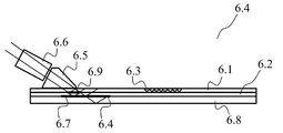
도 6의 (g)는 겹쳐진 방식으로 장착되는 제 1 평행면 슬라이드(6.2), 제 2 평행면 슬라이드(6.2), 및 제 3 평행면 슬라이드(6.8)를 포함하는 광학 가이드를 개략적으로 예시한다. 이러한 광학 가이드는 또한 추출 존(6.3)을 포함한다. 광학 가이드는 또한 제 2 슬라이드(6.2)와 제 3 슬라이드(6.8) 사이에 놓인 제 1 반 반사성 코팅(6.4)과 제 1 슬라이드(6.1)와 제 2 슬라이드(6.2) 사이에 놓인 제 2 반 반사성 코팅(6.9), 및 반사성 코팅(6.7)을 포함한다. 제 1 반 반사성 코팅(6.4), 제 2 반 반사성 코팅(6.9), 및 반사성 코팅(6.7)은 도 3에 관련하여 앞에서 설명된 것과 같이 배치된다.Figure 6 (g) schematically illustrates an optical guide comprising a first parallel slide 6.2, a second parallel slide 6.2, and a third parallel slide 6.8 mounted in an overlapping manner. This optical guide also includes an extraction zone 6.3. The optical guide also comprises a first semi-reflective coating (6.4) placed between the second slide (6.2) and the third slide (6.8) and a second semi-reflective coating (6.4) placed between the first slide (6.1) (6.9), and a reflective coating (6.7). The first semi-reflective coating (6.4), the second semi-reflective coating (6.9), and the reflective coating (6.7) are arranged as previously described with respect to FIG.
광학 가이드는 제 1 슬라이드(6.1) 상에 장착된 주입 피스(6.5) 표면과 렌즈들의 세트(6.6)를 포함하는 주입 장치와 관련되어 사용되고, 이러한 렌즈들의 세트(6.6)는 시준된 빔의 형태로 이미지를 투영할 수 있다. 렌즈들의 세트(6.6)는 시준된 빔을 주입 피스(6.5)로 투과시키고, 이러한 주입 피스(6.5)는 투과된 빔을 제 1 슬라이드(6.1) 내로 주입한다. 그러면 주입된 빔이 반 반사성 코팅(6.4, 6.9)에 의해 부분적으로 반사되고 부분적으로 투과되며, 이미 설명한 바와 같이 반사성 코팅(6.7)에 의해 반사된다.The optical guide is used in connection with an injection device comprising an injection piece (6.5) surface mounted on a first slide (6.1) and a set of lenses (6.6), said set of lenses (6.6) being in the form of a collimated beam The image can be projected. The set of lenses 6.6 transmits the collimated beam to the injection piece 6.5, which injects the transmitted beam into the first slide 6.1. The injected beam is then partially reflected and partially transmitted by the semi-reflective coatings (6.4, 6.9) and reflected by the reflective coating (6.7) as previously described.
도 5는 본 발명에 따른 광학 가이드를 제조하는 방법을 개략적으로 예시한다. 광학 가이드는 그러한 광학 가이드 내로 광 신호를 주입하도록 의도된 주입 존과, 광학 가이드에 의해 이송된 후 광 신호를 제공하도록 의도된 추출 존을 포함한다.5 schematically illustrates a method of manufacturing an optical guide according to the present invention. The optical guide includes an injection zone intended to inject an optical signal into such an optical guide and an extraction zone intended to provide the optical signal after being transported by the optical guide.
도 5에 예시된 제조 방법에서, 이미 언급된 안내 요소들은 평행면 슬라이드들이다. 안내 요소들이 평행하지 않은 면 슬라이드일 때, 특히 안내 요소들 중 하나가 병치된 방식으로, 이미 언급된 주입 존과 추출 존을 포함할 때 동일한 원리들이 적용된다.In the manufacturing method illustrated in Fig. 5, the guiding elements already mentioned are parallel slide. The same principles apply when the guiding elements are non-parallel side slides, particularly when one of the guiding elements comprises a juxtaposed, already mentioned injection zone and extraction zone.
단계(5.1)에서는, 적어도 2개의 슬라이드가 얻어진다. 슬라이드들은 평행한 면들을 가진다. 이미 언급된 바와 같이, 그것들은 동일한 재료 또는 상이한 재료들로 구성될 수 있고, 이는 그것들의 두께에 영향을 준다.In step 5.1, at least two slides are obtained. The slides have parallel sides. As already mentioned, they can be composed of the same material or different materials, which affects their thickness.
후속하는 단계(5.2)에서는 반 반사성 코팅이 하나를 제외한 각각의 슬라이드 상에 퇴적된다. 반 반사성 코팅은 주입 존과 추출 존 사이에 있는 영역에 퇴적된다. 반 반사성 코팅은, 광 신호의 최소 입사각과 상기 반 반사성 코팅이 분리하도록 의도되는 슬라이드들 중 적어도 하나의 두께에 의존적인, 광학 가이드에서의 광 신호의 전파 방향으로의 길이를 가진다.In a subsequent step (5.2), a semi-reflective coating is deposited on each slide except one. A semi-reflective coating is deposited in the region between the injection zone and the extraction zone. The semi-reflective coating has a length in the direction of propagation of the optical signal in the optical guide, which is dependent on the minimum incident angle of the optical signal and the thickness of at least one of the slides intended to separate the semi-reflective coating.
후속하는 단계(5.3)에서는, 슬라이드들이 겹쳐지는 방식으로 조립되어, 각각의 반 반사상 코팅이 2개의 슬라이드로 분리된다.In a subsequent step (5.3), the slides are assembled in a superposed manner such that each semi-reflective coating is separated into two slides.
이러한 조립 단계는 또한 제 3 슬라이드(2.1)에 대해 도 2에 관련하여 제시된 바와 같이 슬라이드들 중 적어도 하나의 에지가 위치하도록 수행될 수 있다.This assembly step may also be performed such that at least one edge of the slides is positioned as shown in relation to Figure 2 for the third slide 2.1.
조립 단계는, 일 변형예에서는 코팅(3.2)에 대해 도 2에 관련하여 위에서 제시된 바와 같이, 전체적으로 반사성인 코팅을 퇴적하는 단계 다음에 올 수 있다.The assembling step may follow a step of depositing a totally reflective coating, as shown above in connection with FIG. 2 for coating 3.2 in one variant.
도 2와 도 3에 관련하여 위에서 제시된 바와 같이, 광학 가이드에서 포함된 슬라이드들의 연속물에서 하나의 슬라이드와 후속하는 슬라이드 사이의 반 반사성 코팅에 의해 투과된 광 신호가 반사 없이 상기 후속하는 슬라이드에 들어가지 않도록 반 반사성 코팅을 퇴적시키는 것과 슬라이드들을 조립하는 것이 이루어질 수 있다.As shown above with respect to Figures 2 and 3, in the series of slides included in the optical guide, the optical signal transmitted by the semi-reflective coating between one slide and the subsequent slide enters the subsequent slide without reflection To deposit a semi-reflective coating and to assemble the slides.
반 반사성 코팅을 퇴적시키는 것과 슬라이드들을 조립하는 것은 또한, 도 4에 관련하여 위에서 제시된 바와 같이, 하나의 반 반사성 코팅에 의해 반사 없이 투과된 광 신호가 광학 가이드에서 포함된 슬라이드들의 연속물에서 후속하는 반 반사성 코팅에 의해 투과되도록 이루어질 수 있다.Depositing the semi-reflective coating and assembling the slides can also be accomplished by exposing the optical signal transmitted without reflection by one semi-reflective coating to a subsequent half of the sequence of slides included in the optical guide, as shown above with respect to FIG. May be made to be transmitted by a reflective coating.
Claims (13)
상기 광학 가이드 내로 광 신호를 주입하도록 의도된 주입 존과, 상기 광학 가이드에 의한 이송 후 상기 광 신호를 제공하도록 의도된 추출 존을 포함하고,
겹쳐진 방식으로 적어도 2개의 안내 요소(1.1, 1.2)를 포함하며,
상기 주입 존과 상기 추출 존 사이에 있는 존에서는,
상기 안내 요소가, 상기 광학 가이드에서의 상기 광 신호의 전파 방향으로 길이를 지닌 반 반사성 코팅(1.3)에 의해 서로로부터 부분적으로 분리되고, 상기 길이는 상기 광 신호의 최소 입사각과 상기 반 반사성 코팅이 분리하는 상기 안내 요소들 중 적어도 하나의 두께에 의존적인 것을 특징으로 하는, 광학 가이드.As the optical guide,
An injection zone intended to inject optical signals into the optical guide and an extraction zone intended to provide the optical signal after transfer by the optical guide,
Comprising at least two guide elements (1.1, 1.2) in a superposed manner,
In the zone between the injection zone and the extraction zone,
Wherein said guide elements are partly separated from each other by a semi-reflective coating (1.3) having a length in the direction of propagation of said optical signal in said optical guide, said length being defined by a minimum incident angle of said optical signal and said semi-reflective coating Wherein said guide element is dependent on the thickness of at least one of said guiding elements to be separated.
상기 반 반사성 코팅의 상기 길이는 상기 반 반사성 코팅 상의 상기 광 신호의 적어도 2회의 리바운드를 허용하도록 정해지는 것을 특징으로 하는, 광학 가이드.The method according to claim 1,
Wherein the length of the semi-reflective coating is determined to allow at least two rebounds of the optical signal on the semi-reflective coating.
상기 반 반사성 코팅의 반사율과 투과율은 실질적으로 같은 것을 특징으로 하는, 광학 가이드.3. The method according to claim 1 or 2,
Wherein the reflectivity and transmittance of the semi-reflective coating are substantially the same.
겹쳐진 방식으로, 안내 요소들의 연속물을 형성하는 적어도 3개의 안내 요소(1.1, 1.2, 4.1)를 포함하고, 반 반사성 코팅(1.3, 4.2)이 후속하는 안내 요소로부터 각각의 안내 요소를 부분적으로 분리하며, 반 반사성 코팅에 의해 투과된 광 신호가 중간 반사 없이 후속하는 반 반사성 코팅에 의해 투과되도록 배치되는 것을 특징으로 하는, 광학 가이드.3. The method according to claim 1 or 2,
Characterized in that it comprises at least three guiding elements (1.1, 1.2, 4.1) forming a series of guiding elements in a superposed manner and partially separating each guiding element from the guiding elements following the semireflective coating (1.3, 4.2) Wherein the optical signal transmitted by the semi-reflective coating is arranged to be transmitted by a subsequent semi-reflective coating without intermediate reflection.
각각의 반 반사성 코팅은 안내 요소들의 연속물에서의 위치에 의존적인 반사율을 가지고, 하나의 반 반사성 코팅(4.2)은 이러한 반 반사성 코팅의 반사율보다 높은 반사율을 가지는 또 다른 반 반사성 코팅(1.3)에 의해 투과되는 광 신호를 투과시키는 것을 특징으로 하는, 광학 가이드.5. The method of claim 4,
Each of the semi-reflective coatings has a reflectivity dependent on the position in the series of guide elements, and one semi-reflective coating (4.2) is formed by another semi-reflective coating (1.3) having a reflectivity higher than that of this reflective coating And transmits the optical signal to be transmitted.
상기 안내 요소들은 동일한 두께를 가지는 것을 특징으로 하는, 광학 가이드.6. The method according to any one of claims 1 to 5,
Characterized in that the guide elements have the same thickness.
상기 안내 요소들을 동일한 재료로 구성되는 것을 특징으로 하는, 광학 가이드.The method according to claim 6,
Characterized in that the guide elements are made of the same material.
상기 안내 요소들은 상이한 재료로부터 제조되고, 그것들의 두께는 그것들의 굴절률과 광 신호의 최소 입사각에 의존적인 것을 특징으로 하는, 광학 가이드.6. The method according to any one of claims 1 to 5,
Wherein the guide elements are made from different materials and their thickness depends on their refractive index and minimum incident angle of the optical signal.
겹쳐진 방식으로 안내 요소들의 연속물을 형성하는 적어도 3개의 안내 요소(1.1, 1.2, 2.1)를 포함하고, 반 반사성 코팅(1.3, 2.2)이 후속하는 안내 요소로부터 각각의 안내 요소를 부분적으로 분리하며, 하나의 안내 요소와 후속하는 안내 요소 사이의 반 반사성 코팅에 의해 투과된 광 신호가 반사 없이 상기 후속하는 안내 요소에 들어가지 않도록 배치되는 것을 특징으로 하는, 광학 가이드.3. The method according to claim 1 or 2,
Characterized in that it comprises at least three guide elements (1.1, 1.2, 2.1) forming a series of guide elements in a superposed manner, partly separating each guide element from the guide elements following the semi-reflective coating (1.3, 2.2) Characterized in that the optical signal transmitted by the semi-reflective coating between one guiding element and the subsequent guiding element is arranged so that it does not enter the subsequent guiding element without reflection.
안내 요소들의 연속물을 형성하도록 겹쳐진 방식으로 배치된 적어도 3개의 안내 요소들의 그룹을 포함하고, 반 반사성 코팅은 후속하는 안내 요소로부터 각각의 안내 요소를 부분적으로 분리하며, 상기 광학 가이드는 하나의 반 반사성 코팅에 의해 반사 없이 투과된 광 신호가 후속하는 반 반사성 코팅에 의해 투과되도록 배치되고,
적어도 하나의 다른 안내 요소를 포함하고, 반 반사성 코팅이 안내 요소들의 상기 그룹으로부터 이러한 다른 안내 요소를 부분적으로 분리하며, 상기 광학 가이드는 안내 요소들의 상기 그룹에서 반 반사성 코팅에 의해 투과된 광 신호가 반사 없이 상기 다른 안내 요소를 들어가지 않도록 배치되는 것을 특징으로 하는, 광학 가이드.3. The method according to claim 1 or 2,
A group of at least three guide elements arranged in an overlapping manner to form a series of guide elements, the semi-reflective coating partly separating each guide element from a subsequent guide element, The optical signal transmitted without reflection by the coating is arranged to be transmitted by the subsequent semi-reflective coating,
Reflective coating partially separates these other guiding elements from said group of guiding elements, said optical guiding being characterized in that the optical signal transmitted by the semi-reflective coating in said group of guiding elements And is arranged so as not to enter said another guiding element without reflection.
하나의 안내 요소와 후속하는 안내 요소 사이의 반 반사성 코팅에 의해 투과된 광 신호가 반사 없이 상기 후속하는 안내 요소로 들어가지 않도록 하기 위해, 상기 안내 요소와 상기 후속하는 안내 요소는 반사성 코팅(3.2)에 의해 부분적으로 분리되는 것을 특징으로 하는, 광학 가이드.11. The method according to claim 9 or 10,
The guiding element and the subsequent guiding element are arranged in the same direction as the reflective coating 3.2 so that the optical signal transmitted by the semi-reflective coating between one guiding element and the subsequent guiding element does not enter the latter without reflection, Is partially separated by an optical guide.
하나의 안내 요소와 후속하는 안내 요소 사이의 반 반사성 코팅에 의해 투과된 광 신호가 상기 후속하는 안내 요소로 들어가지 않도록 하기 위해, 상기 반 반사성 코팅에 의해 광 신호가 투과되는 상기 광학 가이드의 존에는 상기 후속하는 안내 요소(2.1)가 존재하지 않는 것을 특징으로 하는, 광학 가이드.11. The method according to claim 9 or 10,
In order to prevent an optical signal transmitted by a semi-reflective coating between one guiding element and a subsequent guiding element from entering the subsequent guiding element, the zone of the optical guide through which the optical signal is transmitted by the semi-reflective coating Characterized in that said subsequent guiding element (2.1) is absent.
상기 광학 가이드는 상기 광학 가이드 내로 광 신호를 주입하도록 의도된 주입 존과 상기 광학 가이드에 의한 이송 후 상기 광 신호를 제공하도록 의도된 추출 존을 포함하고,
- 적어도 2개의 안내 요소를 얻는 단계(5.1);
- 상기 주입 존과 상기 추출 존 사이에 있는 존에서, 하나를 제외한 각각의 안내 요소 상에 반 반사성 코팅을 퇴적시키는 단계(5.2)로서, 상기 반 반사성 코팅은 상기 광학 가이드에서의 상기 광 신호의 전파 방향으로 길이를 가지고, 상기 길이는 상기 광 신호의 최소 입사각과, 상기 반사성 코팅이 분리하도록 의도되는 안내 요소들 중 적어도 하나의 두께에 의존적인, 퇴적 단계(5.2);
- 각각의 반 반사성 코팅이 2개의 안내 요소를 분리하도록, 겹쳐진 방식으로 안내 요소들을 조립하는 단계(5.3)를 포함하는 것을 특징으로 하는, 광학 가이드를 제조하는 방법.A method of manufacturing an optical guide,
The optical guide comprising an injection zone intended to inject optical signals into the optical guide and an extraction zone intended to provide the optical signal after transfer by the optical guide,
- obtaining (5.1) at least two guide elements;
- depositing (5.2) a semi-reflective coating on each of the guide elements except one, in a zone between the injection zone and the extraction zone, the semi-reflective coating comprising a propagation of the optical signal in the optical guide (5.2), wherein said length is dependent on a minimum incident angle of said optical signal and a thickness of at least one of said guide elements intended to separate said reflective coating;
- assembling (5.3) the guide elements in a superposed manner so that each semi-reflective coating separates the two guide elements.
Applications Claiming Priority (3)
| Application Number | Priority Date | Filing Date | Title |
|---|---|---|---|
| FR1161561A FR2983976B1 (en) | 2011-12-13 | 2011-12-13 | OPTICAL GUIDE WITH OVERLAY GUIDE ELEMENTS AND METHOD OF MANUFACTURE |
| FR11/61561 | 2011-12-13 | ||
| PCT/EP2012/074693 WO2013087518A1 (en) | 2011-12-13 | 2012-12-06 | Optical guide with superposed guidance elements and method of manufacture |
Publications (1)
| Publication Number | Publication Date |
|---|---|
| KR20140102258A true KR20140102258A (en) | 2014-08-21 |
Family
ID=47356033
Family Applications (1)
| Application Number | Title | Priority Date | Filing Date |
|---|---|---|---|
| KR1020147017575A KR20140102258A (en) | 2011-12-13 | 2012-12-06 | Optical guide with superimposed guidance elements and method of manufacture |
Country Status (7)
| Country | Link |
|---|---|
| US (1) | US9435955B2 (en) |
| EP (1) | EP2791717B1 (en) |
| JP (1) | JP2015501952A (en) |
| KR (1) | KR20140102258A (en) |
| CN (1) | CN104254792A (en) |
| FR (1) | FR2983976B1 (en) |
| WO (1) | WO2013087518A1 (en) |
Cited By (3)
| Publication number | Priority date | Publication date | Assignee | Title |
|---|---|---|---|---|
| KR20180110387A (en) | 2017-03-29 | 2018-10-10 | 신주성 | Spices supply |
| KR20190072838A (en) * | 2017-12-18 | 2019-06-26 | 삼성전자주식회사 | Optical system and Wearable display apparatus haivng the same |
| KR20190079581A (en) * | 2016-11-08 | 2019-07-05 | 루머스 리미티드 | Light guide device with optical cut-off edge and method of manufacturing the same |
Families Citing this family (38)
| Publication number | Priority date | Publication date | Assignee | Title |
|---|---|---|---|---|
| US10048499B2 (en) | 2005-11-08 | 2018-08-14 | Lumus Ltd. | Polarizing optical system |
| EP2824387A1 (en) * | 2013-07-08 | 2015-01-14 | Odelo GmbH | Light guide element, method for producing the same, and illuminant and motor vehicle lamp with such a light guide element |
| FR3012624B1 (en) * | 2013-10-29 | 2018-02-09 | Optinvent | OPTICAL GUIDE ADAPTED TO CREATE TWO LIGHT FINGERPRINTS |
| US9746604B2 (en) * | 2014-01-06 | 2017-08-29 | Agira, Inc. | Light guide apparatus and fabrication method thereof |
| IL235642B (en) | 2014-11-11 | 2021-08-31 | Lumus Ltd | Compact head-mounted display system protected by a hyperfine structure |
| US10222619B2 (en) | 2015-07-12 | 2019-03-05 | Steven Sounyoung Yu | Head-worn image display apparatus for stereoscopic microsurgery |
| WO2017042703A1 (en) | 2015-09-07 | 2017-03-16 | Sabic Global Technologies B.V. | Lighting systems of tailgates with plastic glazing |
| US10597097B2 (en) | 2015-09-07 | 2020-03-24 | Sabic Global Technologies B.V. | Aerodynamic features of plastic glazing of tailgates |
| EP3347220B1 (en) | 2015-09-07 | 2021-04-14 | SABIC Global Technologies B.V. | Surfaces of plastic glazing of tailgates |
| EP3347184B1 (en) | 2015-09-07 | 2022-08-03 | SABIC Global Technologies B.V. | Molding of plastic glazing of tailgates |
| EP3380361B1 (en) | 2015-11-23 | 2021-12-22 | SABIC Global Technologies B.V. | Lighting systems for windows having plastic glazing |
| FR3046850B1 (en) | 2016-01-15 | 2018-01-26 | Universite De Strasbourg | IMPROVED OPTICAL GUIDE AND OPTICAL SYSTEM COMPRISING SUCH AN OPTICAL GUIDE |
| CN107783293A (en) * | 2016-08-31 | 2018-03-09 | 中强光电股份有限公司 | Wearable device and light-guide device |
| CN108235739B (en) | 2016-10-09 | 2021-03-16 | 鲁姆斯有限公司 | Aperture multiplier using rectangular waveguides |
| KR102655450B1 (en) | 2017-02-22 | 2024-04-05 | 루머스 리미티드 | Light guide optical assembly |
| CN113341566B (en) | 2017-03-22 | 2023-12-15 | 鲁姆斯有限公司 | Overlapping reflective surface constructions |
| CN114019685A (en) | 2017-05-16 | 2022-02-08 | 奇跃公司 | System and method for mixed reality |
| FI129400B (en) * | 2017-12-22 | 2022-01-31 | Dispelix Oy | Diffractive waveguide element and diffractive waveguide display |
| KR20210013173A (en) | 2018-05-23 | 2021-02-03 | 루머스 리미티드 | Optical system with light guide optical element with partially reflective inner surface |
| US11415812B2 (en) | 2018-06-26 | 2022-08-16 | Lumus Ltd. | Compact collimating optical device and system |
| JP2021529068A (en) | 2018-07-07 | 2021-10-28 | アキュセラ インコーポレイテッド | Device to prevent retinal hypoxia |
| EP3830636A4 (en) | 2018-07-30 | 2022-04-13 | Acucela Inc. | Optical designs of electronic contact lens to decrease myopia progression |
| WO2020183229A1 (en) | 2019-03-12 | 2020-09-17 | Lumus Ltd. | Image projector |
| WO2021022193A1 (en) | 2019-07-31 | 2021-02-04 | Acucela Inc. | Device for projecting images on the retina |
| JP2022547621A (en) | 2019-09-16 | 2022-11-14 | アキュセラ インコーポレイテッド | Assembly process for electronic soft contact lenses designed to inhibit the progression of myopia |
| CN114746797A (en) | 2019-12-08 | 2022-07-12 | 鲁姆斯有限公司 | Optical system with compact image projector |
| WO2021168481A1 (en) | 2020-02-21 | 2021-08-26 | Acucela Inc. | Charging case for electronic contact lens |
| KR20230003191A (en) | 2020-05-13 | 2023-01-05 | 어큐셀라 인코포레이티드 | Electronically switchable glasses for myopia treatment |
| AU2021287803A1 (en) | 2020-06-08 | 2022-10-27 | Acucela Inc. | Stick on devices using peripheral defocus to treat progressive refractive error |
| CN115698832A (en) | 2020-06-08 | 2023-02-03 | 奥克塞拉有限公司 | Asymmetric projection lens for treating astigmatism |
| AU2021289593A1 (en) | 2020-06-08 | 2022-10-20 | Acucela Inc. | Projection of defocused images on the peripheral retina to treat refractive error |
| US11281022B2 (en) | 2020-06-10 | 2022-03-22 | Acucela Inc. | Apparatus and methods for the treatment of refractive error using active stimulation |
| EP4067974A1 (en) | 2021-03-29 | 2022-10-05 | Optinvent | 2d-pupil expansion light guide assembly |
| FR3121236B1 (en) | 2021-03-29 | 2024-02-09 | Optinvent | OPTICAL GUIDE AND CORRESPONDING MANUFACTURING METHOD |
| US11209672B1 (en) | 2021-04-06 | 2021-12-28 | Acucela Inc. | Supporting pillars for encapsulating a flexible PCB within a soft hydrogel contact lens |
| US11366341B1 (en) | 2021-05-04 | 2022-06-21 | Acucela Inc. | Electronic case for electronic spectacles |
| CN115373064A (en) | 2021-05-20 | 2022-11-22 | 中强光电股份有限公司 | Optical waveguide |
| WO2024028746A1 (en) * | 2022-08-01 | 2024-02-08 | Lumus Ltd. | Novel techniques for examination of light optical elements |
Family Cites Families (6)
| Publication number | Priority date | Publication date | Assignee | Title |
|---|---|---|---|---|
| CN1155666A (en) * | 1995-11-27 | 1997-07-30 | 大宇电子株式会社 | Integrated optical pickup system |
| DE69836042T2 (en) * | 1997-03-04 | 2007-02-22 | Matsushita Electric Industrial Co., Ltd., Kadoma | Linear lighting device |
| WO2008153528A1 (en) * | 2007-06-14 | 2008-12-18 | Avery Dennison Corporation | Illuminated graphical and information display |
| US20110001901A1 (en) * | 2007-12-05 | 2011-01-06 | Solomon Jeffrey L | Dual lightguide |
| US7570859B1 (en) * | 2008-07-03 | 2009-08-04 | Microvision, Inc. | Optical substrate guided relay with input homogenizer |
| KR101028210B1 (en) * | 2010-03-26 | 2011-04-11 | 엘지이노텍 주식회사 | Light guide plate and backlight unit having the same |
-
2011
- 2011-12-13 FR FR1161561A patent/FR2983976B1/en not_active Expired - Fee Related
-
2012
- 2012-12-06 CN CN201280067216.9A patent/CN104254792A/en active Pending
- 2012-12-06 JP JP2014546429A patent/JP2015501952A/en not_active Abandoned
- 2012-12-06 EP EP12799552.0A patent/EP2791717B1/en active Active
- 2012-12-06 US US14/365,163 patent/US9435955B2/en active Active - Reinstated
- 2012-12-06 KR KR1020147017575A patent/KR20140102258A/en not_active Application Discontinuation
- 2012-12-06 WO PCT/EP2012/074693 patent/WO2013087518A1/en active Application Filing
Cited By (5)
| Publication number | Priority date | Publication date | Assignee | Title |
|---|---|---|---|---|
| KR20190079581A (en) * | 2016-11-08 | 2019-07-05 | 루머스 리미티드 | Light guide device with optical cut-off edge and method of manufacturing the same |
| KR20180110387A (en) | 2017-03-29 | 2018-10-10 | 신주성 | Spices supply |
| KR20190072838A (en) * | 2017-12-18 | 2019-06-26 | 삼성전자주식회사 | Optical system and Wearable display apparatus haivng the same |
| WO2019124769A1 (en) * | 2017-12-18 | 2019-06-27 | Samsung Electronics Co., Ltd. | Optical system and wearable display apparatus having the same |
| US11360305B2 (en) | 2017-12-18 | 2022-06-14 | Samsung Electronics Co., Ltd. | Optical system and wearable display apparatus having the same |
Also Published As
| Publication number | Publication date |
|---|---|
| EP2791717B1 (en) | 2018-10-24 |
| FR2983976A1 (en) | 2013-06-14 |
| JP2015501952A (en) | 2015-01-19 |
| EP2791717A1 (en) | 2014-10-22 |
| CN104254792A (en) | 2014-12-31 |
| FR2983976B1 (en) | 2017-10-20 |
| WO2013087518A1 (en) | 2013-06-20 |
| US20140334777A1 (en) | 2014-11-13 |
| US9435955B2 (en) | 2016-09-06 |
Similar Documents
| Publication | Publication Date | Title |
|---|---|---|
| KR20140102258A (en) | Optical guide with superimposed guidance elements and method of manufacture | |
| CN107966820B (en) | Waveguide display device | |
| US8854735B2 (en) | Virtual image display system | |
| US8711487B2 (en) | Virtual image display device and manufacturing method of virtual image display device | |
| CN109799613B (en) | Virtual image display device | |
| US9575317B2 (en) | Optical guide suitable for creating two luminous imprints | |
| KR102642251B1 (en) | Compact head-mounted display system having uniform image | |
| US9285590B2 (en) | Optical guidance device and method of manufacturing such a device | |
| JP5686011B2 (en) | Image relay optical system and virtual image display device including the same | |
| JP5421285B2 (en) | Optical waveguide and visual optics | |
| JP5633406B2 (en) | Virtual image display device | |
| CN101446684B (en) | Image display apparatus | |
| US9696479B2 (en) | Optical device and method for manufacturing such a device | |
| CN104678555B (en) | The tooth form of diopter correction inlays planar waveguide optical device | |
| JP2012198264A (en) | Method for manufacturing light guide plate, light guide plate, and virtual image display including the light guide plate | |
| JP5754154B2 (en) | Virtual image display device | |
| JP2012198393A (en) | Light guide plate, and virtual image display device equipped with light guide plate | |
| KR20190095895A (en) | One-piece optical element with diaphragm | |
| CN114660816B (en) | Optical device and AR device | |
| JP2018055085A (en) | Optical element and display device | |
| CN114660816A (en) | Optical device and AR apparatus | |
| CN115629438A (en) | Optical waveguide device and near-to-eye display device |
Legal Events
| Date | Code | Title | Description |
|---|---|---|---|
| WITN | Application deemed withdrawn, e.g. because no request for examination was filed or no examination fee was paid |