KR20140100233A - Sensor lamp having and emergency lamp function - Google Patents
Sensor lamp having and emergency lamp function Download PDFInfo
- Publication number
- KR20140100233A KR20140100233A KR1020130013301A KR20130013301A KR20140100233A KR 20140100233 A KR20140100233 A KR 20140100233A KR 1020130013301 A KR1020130013301 A KR 1020130013301A KR 20130013301 A KR20130013301 A KR 20130013301A KR 20140100233 A KR20140100233 A KR 20140100233A
- Authority
- KR
- South Korea
- Prior art keywords
- emergency
- lamp
- sensor
- sensing
- signal
- Prior art date
Links
Images


Classifications
-
- Y—GENERAL TAGGING OF NEW TECHNOLOGICAL DEVELOPMENTS; GENERAL TAGGING OF CROSS-SECTIONAL TECHNOLOGIES SPANNING OVER SEVERAL SECTIONS OF THE IPC; TECHNICAL SUBJECTS COVERED BY FORMER USPC CROSS-REFERENCE ART COLLECTIONS [XRACs] AND DIGESTS
- Y02—TECHNOLOGIES OR APPLICATIONS FOR MITIGATION OR ADAPTATION AGAINST CLIMATE CHANGE
- Y02B—CLIMATE CHANGE MITIGATION TECHNOLOGIES RELATED TO BUILDINGS, e.g. HOUSING, HOUSE APPLIANCES OR RELATED END-USER APPLICATIONS
- Y02B20/00—Energy efficient lighting technologies, e.g. halogen lamps or gas discharge lamps
- Y02B20/40—Control techniques providing energy savings, e.g. smart controller or presence detection
Landscapes
- Circuit Arrangement For Electric Light Sources In General (AREA)
Abstract
Description
본 발명은 비상등 겸용 센서등에 관한 것으로, 보다 구체적으로는, 평상시에는 센서등으로 기능하고, 비상시에는 비상등으로 기능할 수 있는 비상등 겸용 센서등에 관한 것이다.More particularly, the present invention relates to a sensor and the like which can function as a sensor in normal times and function as an emergency light in an emergency.
일반적으로 비상등은 아파트나 대형 빌딩의 실내 또는 복도 및 계단 등에 설치되어 정전이나 화재와 같은 비상발생시, 자체 건물에 설치되어 있는 자가발전기로 전원을 공급하여 점등시켜 줌으로써, 실내를 밝혀주거나 비상통로를 안내하여 안전을 확보해주는 램프이다.In general, emergency lights are installed in the interior of apartments or large buildings, corridors and stairs, and in case of an emergency such as a power outage or a fire, by supplying power to the self-generator installed in the own building and lighting it, To ensure safety.
센서등은 자외선 센서 및 인체센서를 구비하여 가정의 현관이나 아파트의 엘리베이터 및 계단 또는 복도 등에 설치되어 어두운 곳에서 상기 인체감지센서에 의하여 인체가 감지되었을 때, 미리 설정된 시간동안 점등되도록 함으로써, 상기 가정의 현관이나 아파트의 엘리베이터 및 계단 또는 복도를 밝혀주어 어두운 곳에서도 불편함이 없도록 해주는 램프이다.The sensor is provided with an ultraviolet sensor and a human body sensor so as to be installed in an elevator, a stairway or a corridor of a home or an apartment, so as to be illuminated for a preset time when the human body is detected by the human body detecting sensor in a dark place, It is a lamp which lightens the elevator and the stairs or the corridor of the entrance or the apartment, so that there is no inconvenience in the dark place.
이와 같이 비상시나 어두운 곳에서 불편함을 없애주기 위하여 점등되는 상기 비상등이나 센서등은 가정의 현관이나 대형 건물의 복도 및 계단에 각각 별도로 설치되어 있고, 이 또한 별도의 전원공급장치에 의해 점등되도록 되어 있어, 설치 작업이 번거롭고, 전체적으로 전기 배선도 매우 복잡한 문제점이 있었다. In order to eliminate the inconvenience in an emergency or in a dark place, the emergency light or the sensor is separately installed in the entrance of a home or a corridor and a stairway of a large building, and is also lit by a separate power supply device The installation work is troublesome, and the electric wiring as a whole is very complicated.
도 1에 도시된 바와 같이, 종래의 센서등은 상용전원 공급을 위한 (+),(-) 2개의 배선에 연결되고 배치되어 있고, 비상등은 비상전원이 공급되는 (+),(-) 2개의 배선에 별도로 연결되어 있다. 이는 센서등과 비상등이 하나의 하우징 안에 배치되는 경우나 별도의 하우징에 센서등과 비상등이 각각 구비되는 경우도 마찬가지이다. 즉 센서등에는 평상시의 전원공급선과 연결되어 있고, 비상등에는 비상시의 비상전원공급선과 연결되어 있으며, 센서등과 비상등이 각각 별도로 구비되어, 설치비용이 많이 소요되고 배선설치 작업도 복잡하다는 문제점이 있다.As shown in FIG. 1, a conventional sensor is connected to and disposed on two (+) and (-) wires for supplying commercial power. Emergency lights are connected to (+) and (- Are separately connected to the wirings. This also applies to the case where the sensor and the emergency light are disposed in one housing, or the emergency light is provided in a separate housing and a sensor, respectively. That is, the sensor is connected to a normal power supply line, the emergency light is connected to an emergency power supply line in case of an emergency, and the sensor and the emergency light are separately provided, thus requiring a large installation cost and complicated wiring installation work .
따라서, 본 발명의 목적은 상기한 종래의 문제점을 극복할 수 있는 비상등 겸용 센서등을 제공하는 데 있다.SUMMARY OF THE INVENTION Accordingly, it is an object of the present invention to provide an emergency light sensor and the like which can overcome the above-described problems.
본 발명의 다른 목적은 하나의 램프로 비상등 기능 및 센서등 기능을 함께 수행할 수 있도록 하여, 설치가 간단하고 설치비용을 줄일 수 있으며, 원가절감 및 사용의 편리성이 있는 비상등 겸용 센서등을 제공하는 데 있다. Another object of the present invention is to provide an emergency light sensor that can be easily installed, can reduce installation cost, can be reduced in cost, and is easy to use, by allowing a single lamp to function as an emergency light function and a sensor together I have to.
상기한 기술적 과제들의 일부를 달성하기 위한 본 발명의 구체화에 따라, 본 발명에 따른 비상등 겸용 센서등은, 램프를 구비하여, 상시전원이 공급되는 평상시에는 센서등으로 동작하고, 비상전원이 공급되는 비상시에는 비상등으로 동작하도록 제어되는 것을 특징으로 한다.According to an embodiment of the present invention, an emergency light sensor or the like according to the present invention includes a lamp and operates normally as a sensor when normal power is supplied and an emergency power is supplied And is controlled to operate as an emergency light in an emergency.
상기 비상등 겸용 센서등은, 램프와; 자외선센서 및 인체감지센서를 통해 외부의 밝기 및 인체를 감지하여 센싱점등신호를 발생하는 센싱부와; 비상시에 공급되는 비상전원을 감지하여 비상전원감지신호를 발생하는 비상전원감지부와; 상용전원이 공급되는 평상시에는 센서등으로 동작하여, 상기 센싱점등신호에 응답하여 제1설정시간 동안 상기 램프가 점등되고 상기 제1설정시간 경과이후에는 상기 램프가 소등되도록 제어하고, 비상전원이 공급되는 비상시에는 비상등으로 동작하여, 상기 비상전원감지신호에 응답하여 상기 램프를 점등하여 상기 비상전원이 감지되지 않을 때까지 상기 램프가 점등상태를 유지하도록 제어하는 제어부를 구비할 수 있다.The emergency light sensor or the like includes a lamp; A sensing unit for sensing external brightness and human body through an ultraviolet sensor and a human body detection sensor and generating a sensing lighting signal; An emergency power detection unit for detecting an emergency power supplied at an emergency and generating an emergency power detection signal; The lamp is turned on during a first set time in response to the sensing light signal and the lamp is turned off after the lapse of the first set time, And a controller for controlling the lamp to be turned on until the emergency power is not detected by turning on the lamp in response to the emergency power detection signal.
상기 센싱부는, 자외선 센서와; 인체감지센서와; 상기 자외선 센서에서 자외선 감지신호가 입력되지 않고, 상기 인체감지센서를 통해 인체감지신호가 입력되는 경우에만 상기 센싱점등신호를 발생하는 비교판단부를 구비할 수 있다.The sensing unit includes an ultraviolet sensor; A human body detection sensor; And a comparison determination unit for generating the sensing light signal only when the ultraviolet ray sensing signal is not input to the ultraviolet ray sensor and a human body sensing signal is input through the human body sensing sensor.
상기 제어부는, 센서등 동작시에는 상기 센싱점등신호를 제1설정시간동안 래치하여 점등시간을 제어하고, 비상등 동작시에는 상기 비상전원감지신호에 응답하여 비상점등신호를 발생시키고, 상기 비상전원이 감지되지 않을 때까지 계속적으로 래치하는 시간제어부와; 상기 시간제어부에서 제공되는 센싱점등신호 또는 비상점등신호에 응답하여 상기 램프의 점등 또는 소등을 제어하는 점등제어부를 구비할 수 있다. Wherein the control unit controls the lighting time by latching the sensing lighting signal for a first predetermined time when the sensor or the like is operated, generates an emergency lighting signal in response to the emergency power sensing signal when the emergency lighting operation is performed, A time control unit which continuously latches until it is not detected; And a lighting control unit for controlling the lighting of the lamp in response to a sensing lighting signal or an emergency lighting signal provided by the time control unit.
본 발명에 따르면, 비상등과 센서등의 사용을 위해 2개의 램프를 구비함이 없이, 하나의 램프를 이용하여 비상시에는 비상용으로 사용하고 평상시에는 센서등으로 동작하도록 할 수 있어, 원가절감 및 사용이 편리한 장점이 있다. According to the present invention, since two lamps are not provided for the use of an emergency light and a sensor, a single lamp can be used for emergency use in case of an emergency, and it can be operated as a sensor in a normal case. There is a convenient advantage.
도 1은 종래의 센서등과 비상등의 배선연결도이고,
도 2는 본 발명의 일 실시예에 따른 비상등 겸용 센서등의 배선 연결도이고,
도 3은 본 발명의 일 실시예에 따른 비상등 겸용 센서등의 구성블록도이다.1 is a wiring connection diagram of a conventional sensor or the like and a emergency light,
2 is a wiring connection diagram of a sensor and the like for an emergency light according to an embodiment of the present invention,
3 is a block diagram of a configuration of an emergency light sensor or the like according to an embodiment of the present invention.
이하에서는 본 발명의 바람직한 실시예가, 본 발명이 속하는 기술분야에서 통상의 지식을 가진 자에게 본 발명의 철저한 이해를 제공할 의도 외에는 다른 의도 없이, 첨부한 도면들을 참조로 하여 상세히 설명될 것이다.DETAILED DESCRIPTION OF THE PREFERRED EMBODIMENT Hereinafter, preferred embodiments of the present invention will be described in detail with reference to the accompanying drawings without intending to intend to provide a thorough understanding of the present invention to a person having ordinary skill in the art to which the present invention belongs.
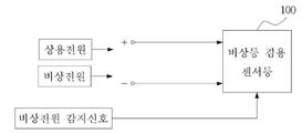
도 2는 본 발명의 일 실시예에 따른 비상등 겸용 센서등의 배선 연결도이고, 도 3은 본 발명의 일 실시예에 따른 비상등 겸용 센서등의 구성블록도이다.FIG. 2 is a wiring diagram of an emergency light sensor or the like according to an embodiment of the present invention, and FIG. 3 is a block diagram of a configuration of a sensor and the like for an emergency light according to an embodiment of the present invention.
도 2에 도시된 바와 같이, 본 발명의 일 실시예에 따른 비상등 겸용 센서등(100)은 상용전원 또는 비상전원이 공급되기 위한 (+),(-) 배선에 하나의 비상등 겸용 센서등이 연결되는 구조를 가진다. 그리고 비상전원이 공급될 때 이를 감지하기 위한 비상전원 감지신호가 제공되기 위한 배선이 연결된다. 상기 비상전원 감지신호는 비상전원이 공급될 때 동작되는 스위치를 통해 비상전원 배선과 연결되도록 하는 것도 가능하다.As shown in FIG. 2, the
이에 따라 상기 비상등 겸용 센서등(100)은, 램프(140)를 구비하여, 하나의 램프가 상용전원이 공급되는 평상시에는 센서등으로 동작하고, 비상전원이 공급되는 비상시에는 비상등으로 동작하도록 제어하게 된다.Accordingly, the
도 3에 도시된 바와 같이, 본 발명의 일 실시예에 따른 비상등 겸용 센서등(100)은 센싱부(110), 비상전원 감지부(130), 제어부(120), 및 램프(140)를 구비한다.3, the
상기 센싱부(110)는 자외선센서(112) 및 인체감지센서(114)를 통해 외부의 밝기 및 인체를 감지하여 센싱점등신호(C)를 발생하게 된다.The
즉 상기 센싱부(110)는 자외선 센서(112), 인체감지센서(114), 비교판단부(116)를 구비한다.That is, the
상기 자외선 센서(112)는 상기 램프(140) 주위의 자외선을 감지하여 감지신호(S1)를 발생시킨다. 자외선은 햇빛이 존재하는 경우에 발생되는 경우가 일반적이므로, 자외선 감지여부를 통해 주변의 밝기를 알 수 있게 된다. 즉 자외선 센서(112)를 통해 자외선이 감지되는 경우에는 상기 램프(140)를 점등할 필요가 없는 것이다.The
상기 인체감지센서(114)는 인체를 감지하기 위한 것으로, 인체의 열을 감지하기 위한 적외선 센서나 인체의 동작을 감지하기 위한 동작감지센서 등의 이용될 수 있다. The human
상기 비교판단부(116)는 상기 자외선 센서(112)에서 자외선 감지신호(S1)가 입력되지 않고, 상기 인체감지센서(114)를 통해 인체감지신호(S2)가 입력되는 경우에만 상기 센싱점등신호(C)를 발생하게 된다.The
상기 비상전원 감지부(130)는 비상시에 공급되는 비상전원을 감지하여 비상전원감지신호(S3)를 발생한다. 상기 비상전원 감지부(130)는 정전 등으로 상용전원이 차단되어 비상전원이 공급되는 경우에 상기 비상전원 감지신호(S3)를 발생하게 된다.The emergency
상기 비상전원 감지부(130)는 비상전원이 공급되는 경우에 온 상태가 되는 감지 스위치를 구비하여, 상기 감지 스위치가 온 상태로 되는 경우에 상기 비상전원 감지신호(S3)가 발생되도록 구성할 수 있다. The emergency
상기 제어부(120)는 상용전원이 공급되는 평상시에는 센서등으로 동작하여, 상기 센싱점등신호(C)에 응답하여 제1설정시간(대략 7 내지 12초) 동안 상기 램프(1401)가 점등되고 상기 제1설정시간 경과이후에는 상기 램프(140)가 소등되도록 제어한다.The
그리고 비상전원이 공급되는 비상시에는 비상등으로 동작하여, 상기 비상전원감지신호(S3)에 응답하여 상기 램프(140)를 점등하여 상기 비상전원이 감지되지 않을 때까지 상기 램프(140)가 점등상태를 유지하도록 제어하게 된다.The
상기 제어부(120)는, 시간제어부(122) 및 점등제어부(124)를 구비할 수 있다.The
상기 시간제어부(122)는 센서등 동작시에는 상기 센싱점등신호(C1)를 제1설정시간동안 래치하여 점등시간을 제어하고, 비상등 동작시에는 상기 비상전원감지신호(S3)에 응답하여 비상점등신호(E)를 발생시켜 상기 비상전원이 감지되지 않을 때까지 계속적으로 래치하면서 상기 점등제어부(124)에 제공하게 된다.The
상기 시간제어부(122)는 래치회로 및 래치회로에 연결된 콘덴서를 구비할 수 있다. 상기 콘덴서는 전원이 공급되는 경우에 상기 제1설정시간동안에 충전이 완료되는 커패시턴스를 가질 수 있다. 따라서, 센서등 동작시에 상기 센싱점등신호(C)가 상기 래치회로를 통하여 래치되고, 상기 콘덴서가 충전이 완료되어 하이레벨로 변할 때 까지 즉 제1설정시간 동안 래치 동작이 계속되게 된다. 따라서 센서등 동작시에는 상기 램프(140)가 제1설정시간 동안만 점등되고 그 이후에는 상기 센싱점등신호(C)가 소멸됨에 따라 소등되게 된다.The
비상등 동작시에는, 상기 비상전원 감지부(130)는 비상전원이 공급되는 경우에 온 상태가 되는 감지 스위치가 구비되며, 상기 시간제어부(122)에 구비되는 콘덴서 단자는 상기 감지스위치가 온 상태로 되는 경우에 접지단과 연결되도록 구성될 수 있다. 따라서, 상기 콘덴서로 전원이 공급되지 않으며 전원이 공급된다고 하여도 충전이 완료되지 않게 된다. 따라서, 상기 램프(140)는 소등되지 않는다.In the emergency operation, the emergency
상기 점등제어부(124)는 상기 시간제어부(122)에서 제공되는 센싱점등신호(C) 또는 비상점등신호(E)에 응답하여 상기 램프(140)의 점등 또는 소등을 제어하하게 된다. 즉 상기 센싱점등신호(C) 또는 상기 비상점등신호(E)가 제공되면, 이에 응답하여 상기 램프(140)를 점등시키고, 상기 센싱점등신호(C) 또는 상기 비상점등신호(E)가 제공되지 않으면 이에 응답하여 상기 램프(140)를 소등시키게 된다.The
상기 램프(140)는 LED 램프가 이용될 수 있다.The
상술한 바와 같이, 본 발명에 따르면, 비상등과 센서등의 사용을 위해 2개의 램프를 구비함이 없이, 하나의 램프를 이용하여 비상시에는 비상용으로 사용하고 평상시에는 센서등으로 동작하도록 할 수 있어, 원가절감 및 사용이 편리한 장점이 있다.As described above, according to the present invention, one lamp can be used for emergency use in case of an emergency and a sensor or the like in a normal state without providing two lamps for use of an emergency light and a sensor, There are advantages of cost reduction and convenient use.
상기한 실시예의 설명은 본 발명의 더욱 철저한 이해를 위하여 도면을 참조로 예를 든 것에 불과하므로, 본 발명을 한정하는 의미로 해석되어서는 안될 것이다. 또한, 본 발명이 속하는 기술 분야에서 통상의 지식을 가진 자에게 있어 본 발명의 기본적 원리를 벗어나지 않는 범위 내에서 다양한 변화와 변경이 가능함은 명백하다 할 것이다. The foregoing description of the embodiments is merely illustrative of the present invention with reference to the drawings for a more thorough understanding of the present invention, and thus should not be construed as limiting the present invention. It will be apparent to those skilled in the art that various changes and modifications may be made without departing from the basic principles of the present invention.
110 : 센싱부 120 : 제어부
130 : 비상전원감지부 140 : 램프110: sensing unit 120: control unit
130: emergency power detecting unit 140: lamp
Claims (4)
램프를 구비하여, 상시전원이 공급되는 평상시에는 센서등으로 동작하고, 비상전원이 공급되는 비상시에는 비상등으로 동작하도록 제어되는 것을 특징으로 하는 비상등 겸용 센서등.In the case of an emergency light sensor or the like:
Wherein the emergency light source is controlled to operate as a sensor when the normal power is supplied and to operate as an emergency light when emergency power is supplied.
램프와;
자외선센서 및 인체감지센서를 통해 외부의 밝기 및 인체를 감지하여 센싱점등신호를 발생하는 센싱부와;
비상시에 공급되는 비상전원을 감지하여 비상전원감지신호를 발생하는 비상전원감지부와;
상용전원이 공급되는 평상시에는 센서등으로 동작하여, 상기 센싱점등신호에 응답하여 제1설정시간 동안 상기 램프가 점등되고 상기 제1설정시간 경과이후에는 상기 램프가 소등되도록 제어하고,
비상전원이 공급되는 비상시에는 비상등으로 동작하여, 상기 비상전원감지신호에 응답하여 상기 램프를 점등하여 상기 비상전원이 감지되지 않을 때까지 상기 램프가 점등상태를 유지하도록 제어하는 제어부를 구비함을 특징으로 하는 비상등 겸용 센서등.The emergency light sensor according to claim 1,
A lamp;
A sensing unit for sensing external brightness and human body through an ultraviolet sensor and a human body detection sensor and generating a sensing lighting signal;
An emergency power detection unit for detecting an emergency power supplied at an emergency and generating an emergency power detection signal;
The lamp is turned on for a first set time in response to the sensed lighting signal and the lamp is turned off after the first set time elapses,
And a controller for operating the lamp in an emergency state when the emergency power is supplied and controlling the lamp to remain on until the emergency power is not detected by turning on the lamp in response to the emergency power detection signal And emergency light sensors.
상기 센싱부는,
자외선 센서와;
인체감지센서와;
상기 자외선 센서에서 자외선 감지신호가 입력되지 않고, 상기 인체감지센서를 통해 인체감지신호가 입력되는 경우에만 상기 센싱점등신호를 발생하는 비교판단부를 구비함을 특징으로 하는 비상등 겸용 센서등. The method of claim 2,
The sensing unit includes:
An ultraviolet sensor;
A human body detection sensor;
And a comparison determination unit for generating the sensing light signal only when the ultraviolet ray sensing signal is not input from the ultraviolet ray sensor and a human body sensing signal is inputted through the human body sensing sensor.
상기 제어부는,
센서등 동작시에는 상기 센싱점등신호를 제1설정시간동안 래치하여 점등시간을 제어하고, 비상등 동작시에는 상기 비상전원감지신호에 응답하여 비상점등신호를 발생시키고, 상기 비상전원이 감지되지 않을 때까지 계속적으로 래치하는 시간제어부와;
상기 시간제어부에서 제공되는 센싱점등신호 또는 비상점등신호에 응답하여 상기 램프의 점등 또는 소등을 제어하는 점등제어부를 구비함을 특징으로 하는 비상등 겸용 센서등.
The method of claim 2,
Wherein,
The control unit controls the lighting time by latching the sensing lighting signal for a first predetermined time during operation of a sensor or the like and generates an emergency lighting signal in response to the emergency power detection signal when the emergency lighting operation is in operation, A time control unit for continuously latching the time until a predetermined time elapses;
And a light control unit for controlling the lamp to be turned on or off in response to a sensing light signal or an emergency light signal provided from the time control unit.
Priority Applications (1)
| Application Number | Priority Date | Filing Date | Title |
|---|---|---|---|
| KR1020130013301A KR20140100233A (en) | 2013-02-06 | 2013-02-06 | Sensor lamp having and emergency lamp function |
Applications Claiming Priority (1)
| Application Number | Priority Date | Filing Date | Title |
|---|---|---|---|
| KR1020130013301A KR20140100233A (en) | 2013-02-06 | 2013-02-06 | Sensor lamp having and emergency lamp function |
Publications (1)
| Publication Number | Publication Date |
|---|---|
| KR20140100233A true KR20140100233A (en) | 2014-08-14 |
Family
ID=51746191
Family Applications (1)
| Application Number | Title | Priority Date | Filing Date |
|---|---|---|---|
| KR1020130013301A KR20140100233A (en) | 2013-02-06 | 2013-02-06 | Sensor lamp having and emergency lamp function |
Country Status (1)
| Country | Link |
|---|---|
| KR (1) | KR20140100233A (en) |
Cited By (2)
| Publication number | Priority date | Publication date | Assignee | Title |
|---|---|---|---|---|
| KR101897471B1 (en) | 2017-09-12 | 2018-09-12 | (주)한국디자인사이언스연구소 | Block connecting module and block set having the module |
| KR20210047161A (en) | 2019-10-21 | 2021-04-29 | 박민숙 | Power supply device for sensor lamp providing emergency lamp function |
-
2013
- 2013-02-06 KR KR1020130013301A patent/KR20140100233A/en not_active Application Discontinuation
Cited By (2)
| Publication number | Priority date | Publication date | Assignee | Title |
|---|---|---|---|---|
| KR101897471B1 (en) | 2017-09-12 | 2018-09-12 | (주)한국디자인사이언스연구소 | Block connecting module and block set having the module |
| KR20210047161A (en) | 2019-10-21 | 2021-04-29 | 박민숙 | Power supply device for sensor lamp providing emergency lamp function |
Similar Documents
| Publication | Publication Date | Title |
|---|---|---|
| US7122976B1 (en) | Light management system device and method | |
| CA2611040C (en) | Intellectual lamp unit able to be installed on a conventional lamp socket controlled by a wall switch | |
| KR101723305B1 (en) | Combination emergency lamp and sensor lamp having integration module | |
| KR101733469B1 (en) | Smart switch system | |
| KR100975480B1 (en) | Heat ray wireless transmitter and wireless receiver | |
| KR100933979B1 (en) | Emergency light sensor | |
| KR20140100233A (en) | Sensor lamp having and emergency lamp function | |
| KR100778931B1 (en) | Automatic lighting switch for infant and the disabled | |
| US7298098B2 (en) | Intellectual lamp unit able to be installed on a conventional lamp socket controlled by a wall switch | |
| JP6771198B2 (en) | Sensor device and lighting system | |
| KR20080096167A (en) | Step-light for working in the night and method for control the illumination the using the step-light | |
| KR100940543B1 (en) | Apparatus and method for controlling lighting lamp by digital type | |
| JPH10125475A (en) | Illumination controller | |
| KR20170114840A (en) | Power management system using by human body detecting sensor and the control method thereof | |
| KR101508534B1 (en) | Apparatus and method for toilet lighting | |
| WO2019188421A1 (en) | Audio device, control method, and program | |
| KR20160107959A (en) | Emergency lighting system | |
| KR20050111475A (en) | The method of saving energy based on the human sensing technique and the same apparatus | |
| KR20160136490A (en) | Automatic switch system include PIR sensor and count sensor | |
| KR102151979B1 (en) | LED converter associated type illumination control system co-functioning as warning light device | |
| KR101208901B1 (en) | Light control system using power line communication | |
| KR200449356Y1 (en) | Sensor switch | |
| KR101699374B1 (en) | The lighting control system comprising a remote control device for transmitting and receiving to detect a power failure and the recovery | |
| TWM511176U (en) | Integrating type lighting control device with LED lighting | |
| KR20220107591A (en) | Multi-Concent plugged into a bulb socket with remote controllable emergency lights |
Legal Events
| Date | Code | Title | Description |
|---|---|---|---|
| A201 | Request for examination | ||
| E902 | Notification of reason for refusal | ||
| E601 | Decision to refuse application |