KR20140099276A - Vehicle and power transmission system - Google Patents
Vehicle and power transmission system Download PDFInfo
- Publication number
- KR20140099276A KR20140099276A KR1020147016692A KR20147016692A KR20140099276A KR 20140099276 A KR20140099276 A KR 20140099276A KR 1020147016692 A KR1020147016692 A KR 1020147016692A KR 20147016692 A KR20147016692 A KR 20147016692A KR 20140099276 A KR20140099276 A KR 20140099276A
- Authority
- KR
- South Korea
- Prior art keywords
- power
- battery
- power transmission
- vehicle
- reception device
- Prior art date
Links
Images


Classifications
-
- B—PERFORMING OPERATIONS; TRANSPORTING
- B60—VEHICLES IN GENERAL
- B60L—PROPULSION OF ELECTRICALLY-PROPELLED VEHICLES; SUPPLYING ELECTRIC POWER FOR AUXILIARY EQUIPMENT OF ELECTRICALLY-PROPELLED VEHICLES; ELECTRODYNAMIC BRAKE SYSTEMS FOR VEHICLES IN GENERAL; MAGNETIC SUSPENSION OR LEVITATION FOR VEHICLES; MONITORING OPERATING VARIABLES OF ELECTRICALLY-PROPELLED VEHICLES; ELECTRIC SAFETY DEVICES FOR ELECTRICALLY-PROPELLED VEHICLES
- B60L50/00—Electric propulsion with power supplied within the vehicle
- B60L50/10—Electric propulsion with power supplied within the vehicle using propulsion power supplied by engine-driven generators, e.g. generators driven by combustion engines
- B60L50/16—Electric propulsion with power supplied within the vehicle using propulsion power supplied by engine-driven generators, e.g. generators driven by combustion engines with provision for separate direct mechanical propulsion
-
- B—PERFORMING OPERATIONS; TRANSPORTING
- B60—VEHICLES IN GENERAL
- B60L—PROPULSION OF ELECTRICALLY-PROPELLED VEHICLES; SUPPLYING ELECTRIC POWER FOR AUXILIARY EQUIPMENT OF ELECTRICALLY-PROPELLED VEHICLES; ELECTRODYNAMIC BRAKE SYSTEMS FOR VEHICLES IN GENERAL; MAGNETIC SUSPENSION OR LEVITATION FOR VEHICLES; MONITORING OPERATING VARIABLES OF ELECTRICALLY-PROPELLED VEHICLES; ELECTRIC SAFETY DEVICES FOR ELECTRICALLY-PROPELLED VEHICLES
- B60L50/00—Electric propulsion with power supplied within the vehicle
- B60L50/50—Electric propulsion with power supplied within the vehicle using propulsion power supplied by batteries or fuel cells
- B60L50/60—Electric propulsion with power supplied within the vehicle using propulsion power supplied by batteries or fuel cells using power supplied by batteries
- B60L50/61—Electric propulsion with power supplied within the vehicle using propulsion power supplied by batteries or fuel cells using power supplied by batteries by batteries charged by engine-driven generators, e.g. series hybrid electric vehicles
-
- B—PERFORMING OPERATIONS; TRANSPORTING
- B60—VEHICLES IN GENERAL
- B60L—PROPULSION OF ELECTRICALLY-PROPELLED VEHICLES; SUPPLYING ELECTRIC POWER FOR AUXILIARY EQUIPMENT OF ELECTRICALLY-PROPELLED VEHICLES; ELECTRODYNAMIC BRAKE SYSTEMS FOR VEHICLES IN GENERAL; MAGNETIC SUSPENSION OR LEVITATION FOR VEHICLES; MONITORING OPERATING VARIABLES OF ELECTRICALLY-PROPELLED VEHICLES; ELECTRIC SAFETY DEVICES FOR ELECTRICALLY-PROPELLED VEHICLES
- B60L50/00—Electric propulsion with power supplied within the vehicle
- B60L50/50—Electric propulsion with power supplied within the vehicle using propulsion power supplied by batteries or fuel cells
- B60L50/60—Electric propulsion with power supplied within the vehicle using propulsion power supplied by batteries or fuel cells using power supplied by batteries
- B60L50/64—Constructional details of batteries specially adapted for electric vehicles
-
- B—PERFORMING OPERATIONS; TRANSPORTING
- B60—VEHICLES IN GENERAL
- B60L—PROPULSION OF ELECTRICALLY-PROPELLED VEHICLES; SUPPLYING ELECTRIC POWER FOR AUXILIARY EQUIPMENT OF ELECTRICALLY-PROPELLED VEHICLES; ELECTRODYNAMIC BRAKE SYSTEMS FOR VEHICLES IN GENERAL; MAGNETIC SUSPENSION OR LEVITATION FOR VEHICLES; MONITORING OPERATING VARIABLES OF ELECTRICALLY-PROPELLED VEHICLES; ELECTRIC SAFETY DEVICES FOR ELECTRICALLY-PROPELLED VEHICLES
- B60L50/00—Electric propulsion with power supplied within the vehicle
- B60L50/50—Electric propulsion with power supplied within the vehicle using propulsion power supplied by batteries or fuel cells
- B60L50/60—Electric propulsion with power supplied within the vehicle using propulsion power supplied by batteries or fuel cells using power supplied by batteries
- B60L50/66—Arrangements of batteries
-
- B—PERFORMING OPERATIONS; TRANSPORTING
- B60—VEHICLES IN GENERAL
- B60L—PROPULSION OF ELECTRICALLY-PROPELLED VEHICLES; SUPPLYING ELECTRIC POWER FOR AUXILIARY EQUIPMENT OF ELECTRICALLY-PROPELLED VEHICLES; ELECTRODYNAMIC BRAKE SYSTEMS FOR VEHICLES IN GENERAL; MAGNETIC SUSPENSION OR LEVITATION FOR VEHICLES; MONITORING OPERATING VARIABLES OF ELECTRICALLY-PROPELLED VEHICLES; ELECTRIC SAFETY DEVICES FOR ELECTRICALLY-PROPELLED VEHICLES
- B60L53/00—Methods of charging batteries, specially adapted for electric vehicles; Charging stations or on-board charging equipment therefor; Exchange of energy storage elements in electric vehicles
- B60L53/10—Methods of charging batteries, specially adapted for electric vehicles; Charging stations or on-board charging equipment therefor; Exchange of energy storage elements in electric vehicles characterised by the energy transfer between the charging station and the vehicle
- B60L53/12—Inductive energy transfer
- B60L53/122—Circuits or methods for driving the primary coil, e.g. supplying electric power to the coil
-
- B—PERFORMING OPERATIONS; TRANSPORTING
- B60—VEHICLES IN GENERAL
- B60L—PROPULSION OF ELECTRICALLY-PROPELLED VEHICLES; SUPPLYING ELECTRIC POWER FOR AUXILIARY EQUIPMENT OF ELECTRICALLY-PROPELLED VEHICLES; ELECTRODYNAMIC BRAKE SYSTEMS FOR VEHICLES IN GENERAL; MAGNETIC SUSPENSION OR LEVITATION FOR VEHICLES; MONITORING OPERATING VARIABLES OF ELECTRICALLY-PROPELLED VEHICLES; ELECTRIC SAFETY DEVICES FOR ELECTRICALLY-PROPELLED VEHICLES
- B60L53/00—Methods of charging batteries, specially adapted for electric vehicles; Charging stations or on-board charging equipment therefor; Exchange of energy storage elements in electric vehicles
- B60L53/10—Methods of charging batteries, specially adapted for electric vehicles; Charging stations or on-board charging equipment therefor; Exchange of energy storage elements in electric vehicles characterised by the energy transfer between the charging station and the vehicle
- B60L53/14—Conductive energy transfer
- B60L53/16—Connectors, e.g. plugs or sockets, specially adapted for charging electric vehicles
-
- B—PERFORMING OPERATIONS; TRANSPORTING
- B60—VEHICLES IN GENERAL
- B60L—PROPULSION OF ELECTRICALLY-PROPELLED VEHICLES; SUPPLYING ELECTRIC POWER FOR AUXILIARY EQUIPMENT OF ELECTRICALLY-PROPELLED VEHICLES; ELECTRODYNAMIC BRAKE SYSTEMS FOR VEHICLES IN GENERAL; MAGNETIC SUSPENSION OR LEVITATION FOR VEHICLES; MONITORING OPERATING VARIABLES OF ELECTRICALLY-PROPELLED VEHICLES; ELECTRIC SAFETY DEVICES FOR ELECTRICALLY-PROPELLED VEHICLES
- B60L53/00—Methods of charging batteries, specially adapted for electric vehicles; Charging stations or on-board charging equipment therefor; Exchange of energy storage elements in electric vehicles
- B60L53/30—Constructional details of charging stations
- B60L53/35—Means for automatic or assisted adjustment of the relative position of charging devices and vehicles
- B60L53/36—Means for automatic or assisted adjustment of the relative position of charging devices and vehicles by positioning the vehicle
-
- B—PERFORMING OPERATIONS; TRANSPORTING
- B60—VEHICLES IN GENERAL
- B60K—ARRANGEMENT OR MOUNTING OF PROPULSION UNITS OR OF TRANSMISSIONS IN VEHICLES; ARRANGEMENT OR MOUNTING OF PLURAL DIVERSE PRIME-MOVERS IN VEHICLES; AUXILIARY DRIVES FOR VEHICLES; INSTRUMENTATION OR DASHBOARDS FOR VEHICLES; ARRANGEMENTS IN CONNECTION WITH COOLING, AIR INTAKE, GAS EXHAUST OR FUEL SUPPLY OF PROPULSION UNITS IN VEHICLES
- B60K1/00—Arrangement or mounting of electrical propulsion units
- B60K1/04—Arrangement or mounting of electrical propulsion units of the electric storage means for propulsion
- B60K2001/0405—Arrangement or mounting of electrical propulsion units of the electric storage means for propulsion characterised by their position
- B60K2001/0416—Arrangement in the rear part of the vehicle
-
- B—PERFORMING OPERATIONS; TRANSPORTING
- B60—VEHICLES IN GENERAL
- B60L—PROPULSION OF ELECTRICALLY-PROPELLED VEHICLES; SUPPLYING ELECTRIC POWER FOR AUXILIARY EQUIPMENT OF ELECTRICALLY-PROPELLED VEHICLES; ELECTRODYNAMIC BRAKE SYSTEMS FOR VEHICLES IN GENERAL; MAGNETIC SUSPENSION OR LEVITATION FOR VEHICLES; MONITORING OPERATING VARIABLES OF ELECTRICALLY-PROPELLED VEHICLES; ELECTRIC SAFETY DEVICES FOR ELECTRICALLY-PROPELLED VEHICLES
- B60L2210/00—Converter types
- B60L2210/10—DC to DC converters
-
- B—PERFORMING OPERATIONS; TRANSPORTING
- B60—VEHICLES IN GENERAL
- B60L—PROPULSION OF ELECTRICALLY-PROPELLED VEHICLES; SUPPLYING ELECTRIC POWER FOR AUXILIARY EQUIPMENT OF ELECTRICALLY-PROPELLED VEHICLES; ELECTRODYNAMIC BRAKE SYSTEMS FOR VEHICLES IN GENERAL; MAGNETIC SUSPENSION OR LEVITATION FOR VEHICLES; MONITORING OPERATING VARIABLES OF ELECTRICALLY-PROPELLED VEHICLES; ELECTRIC SAFETY DEVICES FOR ELECTRICALLY-PROPELLED VEHICLES
- B60L2210/00—Converter types
- B60L2210/30—AC to DC converters
-
- B—PERFORMING OPERATIONS; TRANSPORTING
- B60—VEHICLES IN GENERAL
- B60Y—INDEXING SCHEME RELATING TO ASPECTS CROSS-CUTTING VEHICLE TECHNOLOGY
- B60Y2200/00—Type of vehicle
- B60Y2200/90—Vehicles comprising electric prime movers
- B60Y2200/92—Hybrid vehicles
-
- Y—GENERAL TAGGING OF NEW TECHNOLOGICAL DEVELOPMENTS; GENERAL TAGGING OF CROSS-SECTIONAL TECHNOLOGIES SPANNING OVER SEVERAL SECTIONS OF THE IPC; TECHNICAL SUBJECTS COVERED BY FORMER USPC CROSS-REFERENCE ART COLLECTIONS [XRACs] AND DIGESTS
- Y02—TECHNOLOGIES OR APPLICATIONS FOR MITIGATION OR ADAPTATION AGAINST CLIMATE CHANGE
- Y02T—CLIMATE CHANGE MITIGATION TECHNOLOGIES RELATED TO TRANSPORTATION
- Y02T10/00—Road transport of goods or passengers
- Y02T10/60—Other road transportation technologies with climate change mitigation effect
- Y02T10/62—Hybrid vehicles
-
- Y—GENERAL TAGGING OF NEW TECHNOLOGICAL DEVELOPMENTS; GENERAL TAGGING OF CROSS-SECTIONAL TECHNOLOGIES SPANNING OVER SEVERAL SECTIONS OF THE IPC; TECHNICAL SUBJECTS COVERED BY FORMER USPC CROSS-REFERENCE ART COLLECTIONS [XRACs] AND DIGESTS
- Y02—TECHNOLOGIES OR APPLICATIONS FOR MITIGATION OR ADAPTATION AGAINST CLIMATE CHANGE
- Y02T—CLIMATE CHANGE MITIGATION TECHNOLOGIES RELATED TO TRANSPORTATION
- Y02T10/00—Road transport of goods or passengers
- Y02T10/60—Other road transportation technologies with climate change mitigation effect
- Y02T10/70—Energy storage systems for electromobility, e.g. batteries
-
- Y—GENERAL TAGGING OF NEW TECHNOLOGICAL DEVELOPMENTS; GENERAL TAGGING OF CROSS-SECTIONAL TECHNOLOGIES SPANNING OVER SEVERAL SECTIONS OF THE IPC; TECHNICAL SUBJECTS COVERED BY FORMER USPC CROSS-REFERENCE ART COLLECTIONS [XRACs] AND DIGESTS
- Y02—TECHNOLOGIES OR APPLICATIONS FOR MITIGATION OR ADAPTATION AGAINST CLIMATE CHANGE
- Y02T—CLIMATE CHANGE MITIGATION TECHNOLOGIES RELATED TO TRANSPORTATION
- Y02T10/00—Road transport of goods or passengers
- Y02T10/60—Other road transportation technologies with climate change mitigation effect
- Y02T10/7072—Electromobility specific charging systems or methods for batteries, ultracapacitors, supercapacitors or double-layer capacitors
-
- Y—GENERAL TAGGING OF NEW TECHNOLOGICAL DEVELOPMENTS; GENERAL TAGGING OF CROSS-SECTIONAL TECHNOLOGIES SPANNING OVER SEVERAL SECTIONS OF THE IPC; TECHNICAL SUBJECTS COVERED BY FORMER USPC CROSS-REFERENCE ART COLLECTIONS [XRACs] AND DIGESTS
- Y02—TECHNOLOGIES OR APPLICATIONS FOR MITIGATION OR ADAPTATION AGAINST CLIMATE CHANGE
- Y02T—CLIMATE CHANGE MITIGATION TECHNOLOGIES RELATED TO TRANSPORTATION
- Y02T10/00—Road transport of goods or passengers
- Y02T10/60—Other road transportation technologies with climate change mitigation effect
- Y02T10/72—Electric energy management in electromobility
-
- Y—GENERAL TAGGING OF NEW TECHNOLOGICAL DEVELOPMENTS; GENERAL TAGGING OF CROSS-SECTIONAL TECHNOLOGIES SPANNING OVER SEVERAL SECTIONS OF THE IPC; TECHNICAL SUBJECTS COVERED BY FORMER USPC CROSS-REFERENCE ART COLLECTIONS [XRACs] AND DIGESTS
- Y02—TECHNOLOGIES OR APPLICATIONS FOR MITIGATION OR ADAPTATION AGAINST CLIMATE CHANGE
- Y02T—CLIMATE CHANGE MITIGATION TECHNOLOGIES RELATED TO TRANSPORTATION
- Y02T90/00—Enabling technologies or technologies with a potential or indirect contribution to GHG emissions mitigation
- Y02T90/10—Technologies relating to charging of electric vehicles
- Y02T90/12—Electric charging stations
-
- Y—GENERAL TAGGING OF NEW TECHNOLOGICAL DEVELOPMENTS; GENERAL TAGGING OF CROSS-SECTIONAL TECHNOLOGIES SPANNING OVER SEVERAL SECTIONS OF THE IPC; TECHNICAL SUBJECTS COVERED BY FORMER USPC CROSS-REFERENCE ART COLLECTIONS [XRACs] AND DIGESTS
- Y02—TECHNOLOGIES OR APPLICATIONS FOR MITIGATION OR ADAPTATION AGAINST CLIMATE CHANGE
- Y02T—CLIMATE CHANGE MITIGATION TECHNOLOGIES RELATED TO TRANSPORTATION
- Y02T90/00—Enabling technologies or technologies with a potential or indirect contribution to GHG emissions mitigation
- Y02T90/10—Technologies relating to charging of electric vehicles
- Y02T90/14—Plug-in electric vehicles
Abstract
이 차량(10)은 리어 플로어 패널(31)과, 외부에 설치된 송전 장치(41)로부터 비접촉으로 전력을 수전하는 수전 장치(40)와, 수전 장치(40)에 접속되는 배터리(15)를 구비하고, 배터리(15)는 리어 플로어 패널(31)의 상방에 배치되고, 수전 장치(40)는 리어 플로어 패널(31)의 하방에 배치되고, 평면에서 볼 때, 수전 장치(40)와 배터리(15)는 적어도 일부가 겹치도록 배치되어 있다.The vehicle 10 includes a rear floor panel 31, a power receiving device 40 for receiving electric power from the power transmitting device 41 provided outside in a noncontact manner, and a battery 15 connected to the power receiving device 40 The battery 15 is disposed above the rear floor panel 31 and the water receiving apparatus 40 is disposed below the rear floor panel 31 and the water receiving apparatus 40 and the battery 15 are arranged such that at least a part thereof overlaps.
Description
본 발명은 차량 및 전력 전송 시스템에 관한 것이다.The present invention relates to a vehicle and a power transmission system.
최근 들어, 환경에의 배려로 배터리 등의 전력을 사용하여 구동륜을 구동시키는 하이브리드 차량이나 전기 자동차 등이 착안되어 있다.BACKGROUND ART [0002] In recent years, hybrid vehicles and electric vehicles that drive a driving wheel using electric power such as a battery in consideration of environment have been pointed out.
특히 최근에는, 상기한 바와 같은 배터리를 탑재한 전동 차량에 있어서, 플러그 등을 사용하지 않고 비접촉으로 배터리를 충전 가능한 와이어리스 충전이 착안되어 있다. 그리고, 최근에는 비접촉의 충전 방식에 있어서도 각종 충전 방식이 제안되어 있다.Particularly, recently, in an electric vehicle equipped with a battery as described above, wireless charging capable of charging the battery in a non-contact manner without using a plug or the like has been considered. In recent years, various charging methods have been proposed even in a non-contact charging system.
비접촉의 충전 방식을 이용한 전력 전송 시스템으로서는, 예를 들어 일본 특허 공개 제2008-253131호 공보(특허문헌 1)를 들 수 있다.As a power transmission system using a non-contact charging system, for example, Japanese Patent Application Laid-Open No. 2008-253131 (Patent Document 1) can be cited.
이들 전력 전송 시스템에 있어서는, 차량측에 수전부를 포함하는 수전 장치가 탑재된다. 실제로 차량에 수전 장치를 적재하기 위해서는, 차량의 한정된 스페이스에 수전 장치를 탑재할 필요가 있기 때문에, 수전 장치와 차량측에 배치되는 차량 탑재물의 배치 관계를 검토할 필요가 있다.In these power transmission systems, a water receiving device including a water receiver is mounted on the vehicle side. Actually, in order to load the water receiving apparatus in the vehicle, it is necessary to mount the water receiving apparatus in a limited space of the vehicle. Therefore, it is necessary to examine the arrangement relationship of the water receiving apparatus and the vehicle mount disposed on the vehicle side.
따라서, 본 발명은 상기한 과제를 해결하기 위해 이루어진 것으로, 차량의 한정된 스페이스에 수전 장치를 효율적으로 탑재하는 것이 가능한 구조를 구비하는, 차량 및 전력 전송 시스템을 제공하는 것에 있다.SUMMARY OF THE INVENTION Accordingly, it is an object of the present invention to provide a vehicle and a power transmission system having a structure capable of efficiently mounting a water receiving device in a limited space of a vehicle.
본 발명에 기초한 차량은, 플로어 패널과, 외부에 설치된 송전 장치로부터 비접촉으로 전력을 수전하는 수전 장치와, 상기 수전 장치에 접속되는 배터리를 구비하고, 상기 배터리는, 상기 플로어 패널의 상방에 배치되고, 상기 수전 장치는, 상기 플로어 패널의 하방에 배치되고, 평면에서 볼 때, 상기 수전 장치와 상기 배터리는 적어도 일부가 겹치도록 배치되어 있다.A vehicle based on the present invention includes a floor panel, a power receiving device for receiving power from a power transmitting device provided outside in a noncontact manner, and a battery connected to the power receiving device, wherein the battery is disposed above the floor panel , The water receiving apparatus is disposed below the floor panel, and the water receiving apparatus and the battery are arranged so that at least a part of the water receiving apparatus and the battery overlap each other when viewed from a plane.
다른 형태에 있어서는, 충전기를 더 구비하고, 상기 충전기는, 상기 수전 장치와 상기 배터리 사이에 배치되어 있다.In another aspect, the battery charger further includes a charger, and the charger is disposed between the power receiving device and the battery.
다른 형태에 있어서는, 외부에 설치된 급전 커넥터에 접속되는 충전부를 더 구비하고, 상기 충전기는, 상기 충전부로부터 급전되는 전력을, 상기 배터리의 충전 전력으로 변환함과 함께, 상기 수전 장치로부터 수전한 전력을 상기 배터리의 충전 전력으로 변환한다.According to another aspect of the present invention, there is further provided a charging unit connected to an external power supply connector, wherein the charger converts electric power supplied from the charging unit into charging electric power of the battery, To the charging power of the battery.
다른 형태에 있어서는, 충전 제어 유닛을 더 구비하고, 상기 충전 제어 유닛은, 상기 수전 장치와 상기 배터리 사이에 배치된다.In another aspect, the apparatus further comprises a charge control unit, wherein the charge control unit is disposed between the power reception device and the battery.
다른 형태에 있어서는, 상기 수전 장치의 후단부는, 상기 배터리의 후단부보다도, 당해 차량의 후방측으로 돌출되도록 배치되어 있다.In another aspect, the rear end portion of the water receiving apparatus is arranged so as to project beyond the rear end portion of the battery toward the rear side of the vehicle.
다른 형태에 있어서는, 상기 송전 장치는, 비접촉으로 전력을 상기 수전 장치에 송전하는 송전부를 포함하고, 상기 수전 장치는, 상기 송전부로부터 비접촉으로 전력을 수전하는 수전부를 포함하고, 상기 송전부의 고유 주파수와 상기 수전부의 고유 주파수의 차는, 상기 수전부의 고유 주파수의 10% 이하이다.In another aspect, the power transmission apparatus includes a power transmission unit for transmitting power to the power reception apparatus in a noncontact manner, and the power reception apparatus includes a power reception unit for receiving electric power from the power transmission unit in a noncontact manner, The difference between the natural frequency and the natural frequency of the receiver is not more than 10% of the natural frequency of the receiver.
다른 형태에 있어서는, 상기 송전 장치는, 비접촉으로 전력을 상기 수전 장치에 송전하는 송전부를 포함하고, 상기 수전 장치는, 상기 송전부로부터 비접촉으로 전력을 수전하는 수전부를 포함하고, 상기 수전부와 상기 송전부의 결합 계수는, 0.1 이하이다.In another aspect of the present invention, the power transmission apparatus includes a power transmission unit for transmitting electric power to the power reception apparatus in a noncontact manner, and the power reception apparatus includes a power reception unit for receiving electric power from the power transmission unit in a noncontact manner, The coupling coefficient of the power transmitting portion is 0.1 or less.
다른 형태에 있어서는, 상기 송전 장치는, 비접촉으로 전력을 상기 수전 장치에 송전하는 송전부를 포함하고, 상기 수전 장치는, 상기 송전부로부터 비접촉으로 전력을 수전하는 수전부를 포함하고, 상기 수전부는, 상기 수전부와 상기 송전부의 사이에 형성되고, 또한 특정한 주파수로 진동하는 자계와, 상기 수전부와 상기 송전부의 사이에 형성되고, 또한 특정한 주파수로 진동하는 전계 중 적어도 한쪽을 통하여 상기 송전부로부터 전력을 수전한다.In another aspect, the power transmission apparatus includes a power transmission unit for transmitting electric power to the power reception apparatus in a noncontact manner, wherein the power reception apparatus includes a power reception unit for receiving electric power from the power transmission unit in a noncontact manner, A magnetic field generated between the power receiver and the power transmitting unit and oscillating at a specific frequency and an electric field formed between the power receiver and the power transmitting unit and oscillating at a specific frequency, We collect power from all.
본 발명에 관한 전력 전송 시스템은, 비접촉으로 전력을 송전하는 송전 장치와, 플로어 패널, 상기 송전 장치로부터 수전하는 수전 장치 및 상기 수전 장치에 접속되는 배터리를 포함하는 차량을 구비하고, 상기 배터리는, 상기 플로어 패널의 상방에 배치되고, 상기 수전 장치는, 상기 플로어 패널의 하방에 배치되고, 평면에서 볼 때, 상기 수전 장치와 상기 배터리는 적어도 일부가 겹치도록 배치되어 있다.A power transmission system according to the present invention includes a power transmission device for transmitting power in a noncontact manner, a vehicle including a floor panel, a power reception device for receiving power from the power transmission device, and a battery connected to the power reception device, Wherein the water receiving apparatus is disposed below the floor panel and at least a part of the water receiving apparatus and the battery overlap when viewed in a plan view.
다른 형태에 있어서는, 상기 차량은, 충전기를 더 구비하고, 상기 충전기는, 상기 수전 장치와 상기 배터리 사이에 배치된다.In another aspect, the vehicle further includes a charger, and the charger is disposed between the power receiving device and the battery.
다른 형태에 있어서는, 상기 차량은, 외부에 설치된 급전 커넥터에 접속되는 충전부를 더 구비하고, 상기 충전기는, 상기 충전부로부터 급전되는 전력을, 상기 배터리의 충전 전력으로 변환함과 함께, 상기 수전 장치로부터 수전한 전력을 상기 배터리의 충전 전력으로 변환한다.In another aspect of the present invention, the vehicle further includes a charging unit connected to an external power supply connector, wherein the charger converts power supplied from the charging unit to charging power of the battery, And converts the received power into the charging power of the battery.
다른 형태에 있어서는, 상기 차량은, 충전 제어 유닛을 더 구비하고, 상기 충전 제어 유닛은, 상기 수전 장치와 상기 배터리 사이에 배치된다.In another aspect, the vehicle further includes a charge control unit, wherein the charge control unit is disposed between the power reception device and the battery.
다른 형태에 있어서는, 상기 수전 장치의 후단부는, 상기 배터리의 후단부보다도, 당해 차량의 후방측으로 돌출되도록 배치되어 있다.In another aspect, the rear end portion of the water receiving apparatus is arranged so as to project beyond the rear end portion of the battery toward the rear side of the vehicle.
본 발명에 의하면, 차량의 한정된 스페이스에 수전 장치를 효율적으로 탑재하는 것이 가능한 구조를 구비하는, 차량 및 전력 전송 시스템을 제공하는 것이 가능하게 된다.According to the present invention, it becomes possible to provide a vehicle and a power transmission system having a structure capable of efficiently mounting a water receiving apparatus in a limited space of a vehicle.
도 1은 실시 형태 1에 있어서의 송전 장치, 수전 장치 및 전력 전송 시스템을 탑재한 차량을 모식적으로 설명하는 도면이다.
도 2는 전력 전송 시스템의 시뮬레이션 모델을 도시하는 도면이다.
도 3은 시뮬레이션 결과를 나타내는 도면이다.
도 4는 고유 주파수를 고정한 상태에서, 에어 갭을 변화시켰을 때의 전력 전송 효율과, 공명 코일에 공급되는 전류의 주파수 f의 관계를 나타내는 도면이다.
도 5는 전류원(자류원)으로부터의 거리와 전자계의 강도의 관계를 나타낸 도면이다.
도 6은 실시 형태 1에 있어서의 차량에 탑재되는 수전 장치의 배치를 도시하는 차량의 저면도이다.
도 7은 실시 형태 1에 있어서의 차량에 탑재되는 수전 장치의 배치를 도시하는 부분 횡(좌우 방향)단면도이다.
도 8은 실시 형태 1에 있어서의 차량에 탑재되는 수전 장치의 배치를 도시하는 부분 종(전후 방향)단면도이다.
도 9는 실시 형태 2에 있어서의 차량에 탑재되는 수전 장치의 배치를 도시하는 차량의 사시도이다.
도 10은 실시 형태 2에 있어서의 차량에 탑재되는 수전 장치, 충전기 및 배터리의 회로를 도시하는 도면이다.
도 11은 실시 형태 2에 있어서의 차량에 탑재되는 수전 장치, 충전기 및 배터리의 탑재 상태를 도시하는 사시도이다.
도 12는 실시 형태 2에 있어서의 차량에 탑재되는 수전 장치, 충전기 및 배터리의 탑재 상태를 도시하는 평면도이다.
도 13은 실시 형태 2에 있어서의 차량에 탑재되는 수전 장치, 충전기 및 배터리의 탑재 상태를 도시하는 부분 횡(좌우 방향)단면도이다.
도 14는 실시 형태 2에 있어서의 차량에 탑재되는 수전 장치, 충전기 및 배터리의 탑재 상태를 도시하는 부분 종(전후 방향)단면도이다.
도 15는 실시 형태 2에 있어서의 차량에 탑재되는 수전 장치, 충전기, 충전 제어 유닛 및 배터리의 다른 회로를 도시하는 도면이다.
도 16은 실시 형태 2에 있어서의 차량에 탑재되는 수전 장치, 충전기, 충전 제어 유닛 및 배터리의 탑재 상태를 도시하는 사시도이다.
도 17은 다른 실시 형태에 있어서의 차량에 탑재되는 수전 장치의 배치를 도시하는 차량의 저면도이다.
도 18은 다른 실시 형태에 있어서의 차량에 탑재되는 수전 장치의 배치를 도시하는 차량의 저면도이다.1 is a diagram schematically illustrating a vehicle equipped with a power transmission device, an electricity reception device, and a power transmission system according to the first embodiment.
2 is a diagram showing a simulation model of a power transmission system.
3 is a diagram showing a simulation result.
4 is a graph showing the relationship between the power transmission efficiency when the air gap is changed and the frequency f of the current supplied to the resonance coil in a state where the natural frequency is fixed.
5 is a diagram showing the relationship between the distance from the current source (the current source) and the intensity of the electromagnetic field.
6 is a bottom view of the vehicle showing the arrangement of the water receiving apparatus mounted on the vehicle in the first embodiment.
Fig. 7 is a partial transverse (lateral direction) sectional view showing the arrangement of the water receiving apparatus mounted on the vehicle in the first embodiment. Fig.
8 is a partial longitudinal (longitudinal direction) sectional view showing the arrangement of the water receiving apparatus mounted on the vehicle in the first embodiment.
9 is a perspective view of the vehicle showing the arrangement of the water receiving apparatus mounted on the vehicle in the second embodiment.
10 is a diagram showing a circuit of an electric power receiving device, a charger, and a battery mounted on a vehicle according to the second embodiment.
11 is a perspective view showing a mounting state of a water receiving apparatus, a charger, and a battery mounted on a vehicle according to the second embodiment.
Fig. 12 is a plan view showing the mounting state of a water receiving apparatus, a charger, and a battery mounted on a vehicle according to the second embodiment. Fig.
13 is a partial transverse (lateral direction) cross-sectional view showing a state of mounting a water receiving apparatus, a charger, and a battery mounted on a vehicle according to the second embodiment.
Fig. 14 is a partial longitudinal (longitudinal direction) cross-sectional view showing a state of mounting a water receiving device, a charger, and a battery mounted on a vehicle according to the second embodiment; Fig.
Fig. 15 is a diagram showing another example of a battery receiving apparatus, a charger, a charge control unit, and a battery mounted on a vehicle according to the second embodiment.
Fig. 16 is a perspective view showing the state of mounting of a water receiving apparatus, a charger, a charge control unit, and a battery mounted on a vehicle according to the second embodiment. Fig.
17 is a bottom view of the vehicle showing the arrangement of the water receiving apparatus mounted on the vehicle in another embodiment.
18 is a bottom view of the vehicle showing the arrangement of the water receiving apparatus mounted on the vehicle in another embodiment;
본 발명에 기초한 실시 형태에 있어서의 송전 장치, 수전 장치 및 전력 전송 시스템을 탑재한 차량에 대해, 이하, 도면을 참조하면서 설명한다. 또한, 이하에 설명하는 각 실시 형태에 있어서, 개수, 양 등을 언급하는 경우, 특별히 기재가 있는 경우를 제외하고, 본 발명의 범위는 반드시 그 개수, 양 등으로 한정되는 것은 아니다. 또한, 동일한 부품, 상당 부품에 대해서는, 동일한 참조 번호를 부여하고, 중복되는 설명은 반복하지 않는 경우가 있다. 또한, 각 실시 형태에 있어서의 구성을 적절히 조합하여 사용하는 것은 당초부터 예정되어 있는 것이다.BRIEF DESCRIPTION OF THE DRAWINGS FIG. 1 is a block diagram of a power transmission system according to a first embodiment of the present invention; FIG. In addition, in the embodiments described below, when referring to the number, the amount, and the like, the scope of the present invention is not necessarily limited to the number, the amount, In addition, the same reference numerals are assigned to the same parts and equivalent parts, and redundant descriptions may not be repeated. In addition, it is originally planned to appropriately combine and use the configurations in the respective embodiments.
(실시 형태 1)(Embodiment 1)
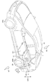
도 1을 참조하여, 본 실시 형태에 따른 전력 전송 시스템을 탑재한 차량에 대해 설명한다. 도 1은 실시 형태에 있어서의 송전 장치, 수전 장치 및 전력 전송 시스템을 탑재한 차량을 모식적으로 설명하는 도면이다.1, a vehicle equipped with the power transmission system according to the present embodiment will be described. BRIEF DESCRIPTION OF THE DRAWINGS Fig. 1 is a diagram schematically illustrating a vehicle equipped with a power transmission apparatus, an electricity reception apparatus, and a power transmission system according to the embodiment. Fig.
본 실시 형태 1에 관한 전력 전송 시스템은, 수전 장치(40)를 포함하는 전동 차량(10)과, 송전 장치(41)를 포함하는 외부 급전 장치(20)를 갖는다. 전동 차량(10)의 수전 장치(40)는 송전 장치(41)가 설치된 주차 스페이스(42)의 소정 위치에 정차하여, 주로, 송전 장치(41)로부터 전력을 수전한다.The power transmission system according to the first embodiment has an
주차 스페이스(42)에는, 전동 차량(10)을 소정의 위치에 정차시키도록, 스프래그나, 주차 위치 및 주차 범위를 나타내는 라인이 설치되어 있다.The
외부 급전 장치(20)는 교류 전원(21)에 접속된 고주파 전력 드라이버(22)와, 고주파 전력 드라이버(22) 등의 구동을 제어하는 제어부(26)와, 이 고주파 전력 드라이버(22)에 접속된 송전 장치(41)를 포함한다. 송전 장치(41)는 송전부(28)와, 전자기 유도 코일(23)을 포함한다. 송전부(28)는 공명 코일(24)과, 공명 코일(24)에 접속된 캐패시터(25)를 포함한다. 전자기 유도 코일(23)은 고주파 전력 드라이버(22)에 전기적으로 접속되어 있다. 또한, 이 도 1에 도시하는 예에 있어서는, 캐패시터(25)가 설치되어 있지만, 캐패시터(25)는 반드시 필수적인 구성인 것은 아니다.The external
송전부(28)는 공명 코일(24)의 인덕턴스와, 공명 코일(24)의 부유 용량 및 캐패시터(25)의 캐패시턴스로 형성된 전기 회로를 포함한다.The
전동 차량(10)은 수전 장치(40)와, 수전 장치(40)에 접속된 정류기(13)와, 이 정류기(13)에 접속된 DC/DC 컨버터(14)와, 이 DC/DC 컨버터(14)에 접속된 배터리(15)와, 파워 컨트롤 유닛[PCU(Power Control Unit)](16)과, 이 파워 컨트롤 유닛(16)에 접속된 모터 유닛(17)과, DC/DC 컨버터(14)와 파워 컨트롤 유닛(16) 등의 구동을 제어하는 차량 ECU(Electronic Control Unit)(18)를 구비한다. 또한, 본 실시 형태에 관한 전동 차량(10)은 도시하지 않은 엔진을 구비한 하이브리드 차량이지만, 모터에 의해 구동되는 차량이라면, 전기 자동차나 연료 전지 차량도 포함한다.The
정류기(13)는 전자기 유도 코일(12)에 접속되어 있고, 전자기 유도 코일(12)로부터 공급되는 교류 전류를 직류 전류로 변환하여, DC/DC 컨버터(14)에 공급한다.The
DC/DC 컨버터(14)는 정류기(13)로부터 공급된 직류 전류의 전압을 조정하여, 배터리(15)에 공급한다. 또한, DC/DC 컨버터(14)는 필수적인 구성은 아니며 생략해도 된다. 이 경우에는, 외부 급전 장치(20)에 임피던스를 정합하기 위한 정합기를 송전 장치(41)와 고주파 전력 드라이버(22) 사이에 설치함으로써, DC/DC 컨버터(14)의 대용을 할 수 있다.The DC /
파워 컨트롤 유닛(16)은 배터리(15)에 접속된 컨버터와, 이 컨버터에 접속된 인버터를 포함하고, 컨버터는, 배터리(15)로부터 공급되는 직류 전류를 조정(승압)하여, 인버터에 공급한다. 인버터는, 컨버터로부터 공급되는 직류 전류를 교류 전류로 변환하여, 모터 유닛(17)에 공급한다.The
모터 유닛(17)은, 예를 들어 3상 교류 모터 등이 채용되어 있고, 파워 컨트롤 유닛(16)의 인버터로부터 공급되는 교류 전류에 의해 구동한다.The
또한, 전동 차량(10)이 하이브리드 차량인 경우에는, 전동 차량(10)은 엔진을 더 구비한다. 모터 유닛(17)은 발전기로서 주로 기능하는 모터 제너레이터와, 전동기로서 주로 기능하는 모터 제너레이터를 포함한다.Further, when the
수전 장치(40)는 수전부(27)와, 전자기 유도 코일(12)을 포함한다. 수전부(27)는 공명 코일(11)과 캐패시터(19)를 포함한다. 공명 코일(11)은 부유 용량을 갖는다. 이로 인해, 수전부(27)는 공명 코일(11)의 인덕턴스와, 공명 코일(11) 및 캐패시터(19)의 캐패시턴스에 의해 형성된 전기 회로를 갖는다. 또한, 캐패시터(19)는 필수적인 구성은 아니고, 생략할 수 있다.The water receiving device (40) includes a power receiver (27) and an electromagnetic induction coil (12). The
본 실시 형태에 따른 전력 전송 시스템에 있어서는, 송전부(28)의 고유 주파수와, 수전부(27)의 고유 주파수의 차는, 수전부(27) 또는 송전부(28)의 고유 주파수의 10% 이하이다. 이와 같은 범위에 각 송전부(28) 및 수전부(27)의 고유 주파수를 설정함으로써, 전력 전송 효율을 높일 수 있다. 한편, 고유 주파수의 차가 수전부(27) 또는 송전부(28)의 고유 주파수의 10%보다도 커지면, 전력 전송 효율이 10%보다 작아져, 배터리(15)의 충전 시간이 길어지는 등의 폐해가 발생한다.The difference between the natural frequency of the
여기서, 송전부(28)의 고유 주파수라 함은, 캐패시터(25)가 설치되어 있지 않은 경우에는, 공명 코일(24)의 인덕턴스와, 공명 코일(24)의 캐패시턴스로 형성된 전기 회로가 자유 진동하는 경우의 진동 주파수를 의미한다. 캐패시터(25)가 설치된 경우에는, 송전부(28)의 고유 주파수라 함은, 공명 코일(24) 및 캐패시터(25)의 캐패시턴스와, 공명 코일(24)의 인덕턴스에 의해 형성된 전기 회로가 자유 진동하는 경우의 진동 주파수를 의미한다. 상기 전기 회로에 있어서, 제동력 및 전기 저항을 제로 또는 실질적으로 제로로 하였을 때의 고유 주파수는, 송전부(28)의 공진 주파수라고도 불린다.Here, the natural frequency of the
마찬가지로, 수전부(27)의 고유 주파수라 함은, 캐패시터(19)가 설치되어 있지 않은 경우에는, 공명 코일(11)의 인덕턴스와, 공명 코일(11)의 캐패시턴스로 형성된 전기 회로가 자유 진동하는 경우의 진동 주파수를 의미한다. 캐패시터(19)가 설치된 경우에는, 수전부(27)의 고유 주파수라 함은, 공명 코일(11) 및 캐패시터(19)의 캐패시턴스와, 공명 코일(11)의 인덕턴스에 의해 형성된 전기 회로가 자유 진동하는 경우의 진동 주파수를 의미한다. 상기 전기 회로에 있어서, 제동력 및 전기 저항을 제로 또는 실질적으로 제로로 하였을 때의 고유 주파수는, 수전부(27)의 공진 주파수라고도 불린다.Likewise, when the
도 2 및 도 3을 사용하여, 고유 주파수의 차와 전력 전송 효율의 관계를 해석한 시뮬레이션 결과에 대해 설명한다. 도 2는 전력 전송 시스템의 시뮬레이션 모델을 도시한다. 전력 전송 시스템(89)은 송전 장치(90)와, 수전 장치(91)를 구비하고, 송전 장치(90)는 전자기 유도 코일(92)과, 송전부(93)를 포함한다. 송전부(93)는 공명 코일(94)과, 공명 코일(94)에 설치된 캐패시터(95)를 포함한다.2 and 3, the simulation result of analyzing the relationship between the difference in natural frequency and the power transmission efficiency will be described. Figure 2 shows a simulation model of a power transmission system. The
수전 장치(91)는 수전부(96)와, 전자기 유도 코일(97)을 구비한다. 수전부(96)는 공명 코일(99)과 이 공명 코일(99)에 접속된 캐패시터(98)를 포함한다.The
공명 코일(94)의 인덕턴스를 인덕턴스 Lt로 하고, 캐패시터(95)의 캐패시턴스를 캐패시턴스 C1로 한다. 공명 코일(99)의 인덕턴스를 인덕턴스 Lr로 하고, 캐패시터(98)의 캐패시턴스를 캐패시턴스 C2로 한다. 이와 같이 각 파라미터를 설정하면, 송전부(93)의 고유 주파수 f1은, 하기하는 수학식 1에 의해 나타내어지고, 수전부(96)의 고유 주파수 f2는, 하기하는 수학식 2에 의해 나타내어진다.The inductance of the
<수학식 1>&Quot; (1) "
f1=1/{2π(Lt×C1)1/2}f1 = 1 / {2 (LtxC1) 1/2 }
<수학식 2>&Quot; (2) "
f2=1/{2π(Lr×C2)1/2}f2 = 1 / {2 (Lr x C2) 1/2 }
여기서, 인덕턴스 Lr 및 캐패시턴스 C1, C2를 고정하고, 인덕턴스 Lt만을 변화시킨 경우에 있어서, 송전부(93) 및 수전부(96)의 고유 주파수 어긋남과, 전력 전송 효율의 관계를 도 3에 나타낸다. 또한, 이 시뮬레이션에 있어서는, 공명 코일(94) 및 공명 코일(99)의 상대적인 위치 관계는 고정된 상태이며, 또한, 송전부(93)에 공급되는 전류의 주파수는 일정하다.3 shows the relationship between the natural frequency shift of the
도 3에 나타내는 그래프 중, 횡축은, 고유 주파수의 어긋남(%)을 나타내고, 종축은, 일정 주파수에서의 전송 효율(%)을 나타낸다. 고유 주파수의 어긋남(%)은 하기 수학식 3에 의해 나타내어진다.In the graph shown in Fig. 3, the abscissa indicates the deviation of the natural frequency (%), and the ordinate indicates the transmission efficiency (%) at a certain frequency. The deviation (%) of the natural frequency is represented by the following equation (3).
<수학식 3>&Quot; (3) "
(고유 주파수의 어긋남)={(f1-f2)/f2}×100(%)(Deviation of natural frequency) = {(f1-f2) / f2} x 100 (%)
도 3으로부터도 명백해진 바와 같이, 고유 주파수의 어긋남(%)이 ±0%인 경우에는, 전력 전송 효율은, 100%에 가깝게 된다. 고유 주파수의 어긋남(%)이 ±5%인 경우에는, 전력 전송 효율은, 40%로 된다. 고유 주파수의 어긋남(%)이 ±10%인 경우에는, 전력 전송 효율은, 10%로 된다. 고유 주파수의 어긋남(%)이 ±15%인 경우에는, 전력 전송 효율은, 5%로 된다. 즉, 고유 주파수의 어긋남(%)의 절대값(고유 주파수의 차)이 수전부(96)의 고유 주파수의 10% 이하의 범위로 되도록 각 송전부 및 수전부의 고유 주파수를 설정함으로써 전력 전송 효율을 높일 수 있는 것을 알 수 있다. 또한, 고유 주파수의 어긋남(%)의 절대값이 수전부(96)의 고유 주파수의 5% 이하로 되도록, 각 송전부 및 수전부의 고유 주파수를 설정함으로써 전력 전송 효율을 보다 높일 수 있는 것을 알 수 있다. 또한, 시뮬레이션 소프트웨어로서는, 전자계 해석 소프트웨어[JMAG(등록 상표):주식회사 JSOL제]를 채용하고 있다.As is clear from Fig. 3, when the natural frequency shift (%) is ± 0%, the power transmission efficiency is close to 100%. When the deviation (%) of the natural frequency is ± 5%, the power transmission efficiency is 40%. When the deviation (%) of the natural frequency is ± 10%, the power transmission efficiency is 10%. When the deviation (%) of the natural frequency is ± 15%, the power transmission efficiency is 5%. That is, by setting the natural frequency of each of the power transmitting unit and the power receiving unit such that the absolute value (difference in natural frequency) of the natural frequency deviation (%) is in the range of 10% or less of the natural frequency of the
이어서, 본 실시 형태에 관한 전력 전송 시스템의 동작에 대해 설명한다.Next, the operation of the power transmission system according to the present embodiment will be described.
도 1에 있어서, 전자기 유도 코일(23)에는, 고주파 전력 드라이버(22)로부터 교류 전력이 공급된다. 전자기 유도 코일(23)에 소정의 교류 전류가 흐르면, 전자기 유도에 의해 공명 코일(24)에도 교류 전류가 흐른다. 이때, 공명 코일(24)을 흐르는 교류 전류의 주파수가 특정한 주파수로 되도록, 전자기 유도 코일(23)에 전력이 공급되어 있다.1, the
공명 코일(24)에 특정한 주파수의 전류가 흐르면, 공명 코일(24)의 주위에는 특정한 주파수로 진동하는 전자계가 형성된다.When a current of a specific frequency flows through the
공명 코일(11)은 공명 코일(24)로부터 소정 범위 내에 배치되어 있고, 공명 코일(11)은 공명 코일(24)의 주위에 형성된 전자계로부터 전력을 수취한다.The
본 실시 형태에 있어서는, 공명 코일(11) 및 공명 코일(24)은 소위, 헬리컬 코일이 채용되어 있다. 이로 인해, 공명 코일(24)의 주위에는, 특정한 주파수로 진동하는 자계가 주로 형성되고, 공명 코일(11)은 당해 자계로부터 전력을 수취한다.In the present embodiment, the
여기서, 공명 코일(24)의 주위에 형성되는 특정한 주파수의 자계에 대해 설명한다. 「특정한 주파수의 자계」는, 전형적으로는, 전력 전송 효율과 공명 코일(24)에 공급되는 전류의 주파수와 관련성을 갖는다. 따라서, 먼저, 전력 전송 효율과, 공명 코일(24)에 공급되는 전류의 주파수의 관계에 대해 설명한다. 공명 코일(24)로부터 공명 코일(11)로 전력을 전송할 때의 전력 전송 효율은, 공명 코일(24) 및 공명 코일(11)의 사이의 거리 등의 다양한 요인에 의해 변화된다. 예를 들어, 송전부(28) 및 수전부(27)의 고유 주파수(공진 주파수)를 고유 주파수 f0으로 하고, 공명 코일(24)에 공급되는 전류의 주파수를 주파수 f3으로 하고, 공명 코일(11) 및 공명 코일(24)의 사이의 에어 갭을 에어 갭 AG로 한다.Here, a magnetic field of a specific frequency formed around the
도 4는 고유 주파수 f0을 고정한 상태에서, 에어 갭 AG를 변화시켰을 때의 전력 전송 효율과, 공명 코일(24)에 공급되는 전류의 주파수 f3의 관계를 나타내는 그래프이다.4 is a graph showing the relation between the power transmission efficiency when the air gap AG is changed and the frequency f3 of the current supplied to the
도 4에 나타내는 그래프에 있어서, 횡축은, 공명 코일(24)에 공급하는 전류의 주파수 f3을 나타내고, 종축은, 전력 전송 효율(%)을 나타낸다. 효율 곡선 L1은, 에어 갭 AG가 작을 때의 전력 전송 효율과, 공명 코일(24)에 공급하는 전류의 주파수 f3의 관계를 모식적으로 나타낸다. 이 효율 곡선 L1에 나타내는 바와 같이, 에어 갭 AG가 작은 경우에는, 전력 전송 효율의 피크는 주파수 f4, f5(f4<f5)에 있어서 발생한다. 에어 갭 AG를 크게 하면, 전력 전송 효율이 높아질 때의 2개의 피크는, 서로 가까워지도록 변화된다. 그리고, 효율 곡선 L2에 나타내는 바와 같이, 에어 갭 AG를 소정 거리보다도 크게 하면, 전력 전송 효율의 피크는 1개로 되고, 공명 코일(24)에 공급하는 전류의 주파수가 주파수 f6일 때에 전력 전송 효율이 피크로 된다. 에어 갭 AG를 효율 곡선 L2의 상태보다도 더욱 크게 하면, 효율 곡선 L3에 나타내는 바와 같이 전력 전송 효율의 피크가 작아진다.In the graph shown in Fig. 4, the abscissa indicates the frequency f3 of the current supplied to the
예를 들어, 전력 전송 효율의 향상을 도모하기 위한 방법으로서 다음과 같은 제1 방법이 생각된다. 제1 방법으로서는, 에어 갭 AG에 맞추어, 도 1에 도시하는 공명 코일(24)에 공급하는 전류의 주파수를 일정하게 하고, 캐패시터(25)나 캐패시터(19)의 캐패시턴스를 변화시킴으로써, 송전부(28)와 수전부(27) 사이에서의 전력 전송 효율의 특성을 변화시키는 방법이 생각된다. 구체적으로는, 공명 코일(24)에 공급되는 전류의 주파수를 일정하게 한 상태에서, 전력 전송 효율이 피크로 되도록, 캐패시터(25) 및 캐패시터(19)의 캐패시턴스를 조정한다. 이 방법에서는, 에어 갭 AG의 크기에 관계없이, 공명 코일(24) 및 공명 코일(11)에 흐르는 전류의 주파수는 일정하다. 또한, 전력 전송 효율의 특성을 변화시키는 방법으로서는, 송전 장치(41)와 고주파 전력 드라이버(22) 사이에 설치된 정합기를 이용하는 방법이나, 컨버터(14)를 이용하는 방법 등을 채용할 수도 있다.For example, the following first method is considered as a method for improving the power transmission efficiency. As a first method, the frequency of the current to be supplied to the
또한, 제2 방법으로서는, 에어 갭 AG의 크기에 기초하여, 공명 코일(24)에 공급하는 전류의 주파수를 조정하는 방법이다. 예를 들어, 도 4에 있어서, 전력 전송 특성이 효율 곡선 L1로 되는 경우에는, 공명 코일(24)에는 주파수가 주파수 f4 또는 주파수 f5인 전류를 공명 코일(24)을 공급한다. 그리고, 주파수 특성이 효율 곡선 L2, L3으로 되는 경우에는, 주파수가 주파수 f6인 전류를 공명 코일(24)에 공급한다. 이 경우에서는, 에어 갭 AG의 크기에 맞추어 공명 코일(24) 및 공명 코일(11)에 흐르는 전류의 주파수를 변화시키게 된다.The second method is a method of adjusting the frequency of the current supplied to the
제1 방법에서는, 공명 코일(24)을 흐르는 전류의 주파수는, 고정된 일정한 주파수로 되고, 제2 방법에서는, 공명 코일(24)을 흐르는 주파수는, 에어 갭 AG에 의해 적절히 변화되는 주파수로 된다. 제1 방법이나 제2 방법 등에 의해, 전력 전송 효율이 높아지도록 설정된 특정한 주파수의 전류가 공명 코일(24)에 공급된다. 공명 코일(24)에 특정한 주파수의 전류가 흐름으로써, 공명 코일(24)의 주위에는, 특정한 주파수로 진동하는 자계(전자계)가 형성된다. 수전부(27)는 수전부(27)와 송전부(28)의 사이에 형성되고, 또한 특정한 주파수로 진동하는 자계를 통하여 송전부(28)로부터 전력을 수전하고 있다. 따라서, 「특정한 주파수로 진동하는 자계」라 함은, 반드시 고정된 주파수의 자계라고 하는 것은 아니다. 또한, 상기한 예에서는, 에어 갭 AG에 착안하여, 공명 코일(24)에 공급하는 전류의 주파수를 설정하도록 하고 있지만, 전력 전송 효율은, 공명 코일(24) 및 공명 코일(11)의 수평 방향의 어긋남 등과 같이 다른 요인에 의해서도 변화되는 것이며, 당해 다른 요인에 기초하여, 공명 코일(24)에 공급하는 전류의 주파수를 조정하는 경우가 있다.In the first method, the frequency of the current flowing through the
또한, 본 실시 형태에서는, 공명 코일로서 헬리컬 코일을 채용한 예에 대해 설명하였지만, 공명 코일로서, 미앤더 라인 등의 안테나 등을 채용한 경우에는, 공명 코일(24)에 특정한 주파수의 전류가 흐름으로써, 특정한 주파수의 전계가 공명 코일(24)의 주위에 형성된다. 그리고, 이 전계를 통과하여, 송전부(28)와 수전부(27) 사이에서 전력 전송이 행해진다.In the present embodiment, an example in which a helical coil is used as the resonance coil has been described. However, when an antenna such as a meander line is used as the resonance coil, a current of a specific frequency flows to the
본 실시 형태에 관한 전력 전송 시스템에 있어서는, 전자계의 「정전계」가 지배적인 근접장(에바네센트장)을 이용함으로써, 송전 및 수전 효율의 향상이 도모되고 있다. 도 5는 전류원(자류원)으로의 거리와 전자계의 강도의 관계를 나타낸 도면이다. 도 5를 참조하여, 전자계는 3개의 성분을 포함한다. 곡선 k1은, 파원으로부터의 거리에 반비례한 성분이며, 「복사 전계」라고 칭해진다. 곡선 k2는, 파원으로부터의 거리의 2승에 반비례한 성분이며, 「유도 전계」라고 칭해진다. 또한, 곡선 k3은, 파원으로부터의 거리의 3승에 반비례한 성분이며, 「정전계」라고 칭해진다. 또한, 전자계의 파장을 「λ」로 하면, 「복사 전계」와 「유도 전계」와 「정전계」의 강도가 대략 동등해지는 거리는, λ/2π라고 나타낼 수 있다.In the power transmission system according to the present embodiment, transmission and power reception efficiencies are improved by using near-field (evanescent field) dominated by the "electrostatic field" of the electromagnetic field. 5 is a diagram showing the relationship between the distance to the current source (the current source) and the intensity of the electromagnetic field. Referring to Fig. 5, the electromagnetic system includes three components. The curve k1 is a component in inverse proportion to the distance from the source, and is referred to as " radiation field ". The curve k2 is a component in inverse proportion to the square of the distance from the source, and is referred to as "induced electric field". The curve k3 is a component in inverse proportion to the third power of the distance from the source, and is called an " electrostatic field. &Quot; If the wavelength of the electromagnetic field is "?, &Quot; the distance at which the intensities of the " radiant electric field ", the " induced electric field "
「정전계」는, 파원으로부터의 거리와 함께 급격하게 전자파의 강도가 감소하는 영역이며, 본 실시 형태에 관한 전력 전송 시스템에서는, 이 「정전계」가 지배적인 근접장(에바네센트장)을 이용하여 에너지(전력)의 전송이 행해진다. 즉, 「정전계」가 지배적인 근접장에 있어서, 근접하는 고유 주파수를 갖는 송전부(28) 및 수전부(27)(예를 들어, 한 쌍의 LC 공진 코일)를 공명시킴으로써, 송전부(28)로부터 다른 쪽의 수전부(27)로 에너지(전력)를 전송한다. 이 「정전계」는 먼 곳에 에너지를 전파하지 않으므로, 먼 곳까지 에너지를 전파하는 「복사 전계」에 의해 에너지(전력)를 전송하는 전자파에 비해, 공명법은 보다 적은 에너지 손실로 송전할 수 있다.The " electrostatic field " is an area where the intensity of the electromagnetic wave suddenly decreases with the distance from the source. In the power transmission system according to this embodiment, the " electrostatic field " And the transfer of energy (electric power) is performed. That is, by resonating the
이와 같이, 본 실시 형태에 관한 전력 전송 시스템에 있어서는, 송전부(28)와 수전부(27)를 전자계에 의해 공진시킴으로써 송전 장치(41)로부터 수전 장치로 전력을 송전하고 있다. 그리고, 송전부(28)와 수전부(27) 사이의 결합 계수(κ)는 바람직하게는 0.1 이하이다. 또한, 결합 계수(κ)는 이 값으로 한정되는 것은 아니고 전력 전송이 양호해지는 다양한 값을 취할 수 있다. 일반적으로, 전자기 유도를 이용한 전력 전송에서는, 송전부와 수전부의 사이의 결합 계수(κ)는 1.0에 가까운 것으로 되어 있다.As described above, in the power transmission system according to the present embodiment, electric power is transmitted from the
본 실시 형태의 전력 전송에 있어서의 송전부(28)와 수전부(27)의 결합을, 예를 들어 「자기 공명 결합」, 「자계(자장) 공명 결합」, 「전자계(전자장) 공진 결합」 또는 「전계(전기장) 공진 결합」이라 한다.The combination of the
「전자계(전자장) 공진 결합」은, 「자기 공명 결합」, 「자계(자장) 공명 결합」, 「전계(전기장) 공진 결합」의 모두를 포함하는 결합을 의미한다."Electromagnetic field (electromagnetic field) resonance coupling" means a combination including both "magnetic resonance coupling", "magnetic field (magnetic field) resonance coupling" and "electric field (electric field) resonance coupling".
본 명세서 중에서 설명한 송전부(28)의 공명 코일(24)과 수전부(27)의 공명 코일(11)은, 코일 형상의 안테나가 채용되어 있기 때문에, 송전부(28)와 수전부(27)는 주로, 자계에 의해 결합되어 있고, 송전부(28)와 수전부(27)는, 「자기 공명 결합」 또는 「자계(자장) 공명 결합」되어 있다.The
또한, 공명 코일(24, 11)로서, 예를 들어 미앤더 라인 등의 안테나를 채용하는 것도 가능하고, 이 경우에는, 송전부(28)와 수전부(27)는 주로, 전계에 의해 결합되어 있다. 이때에는, 송전부(28)와 수전부(27)는, 「전계(전기장) 공진 결합」되어 있다.An antenna such as a meander line may be employed as the resonance coils 24 and 11. In this case, the
[수전 장치(40)][Water receiving device (40)]
도 6에서 도 8을 참조하여, 실시 형태 1에 있어서의 수전 장치(40)의 구체적 구성에 대해 설명한다. 도 6은 본 실시 형태에 있어서의 전동 차량(10)에 탑재되는 수전 장치의 배치를 나타내는 차량의 저면도, 도 7은 본 실시 형태에 있어서의 전동 차량(10)에 탑재되는 수전 장치의 배치를 나타내는 부분 횡(좌우 방향)단면, 도 8은 본 실시 형태에 있어서의 전동 차량(10)에 탑재되는 수전 장치의 배치를 나타내는 부분 종(전후 방향)단면이다.Referring to Fig. 6 to Fig. 8, a specific configuration of the
도 6에 도시한 바와 같이, 전동 차량(10)의 전단부로부터 전륜 타이어(160F)의 후단부까지의 영역을 전방부, 전륜 타이어(160F)로부터 후륜 타이어(160R)의 전단부까지의 영역을 중앙부, 후륜 타이어(160R)의 후단부로부터 전동 차량(10)의 후단부까지의 영역을 후방부라고 칭한다. 이하의 설명에 있어서도 마찬가지이다. 도 7에 도시한 바와 같이, 전동 차량(10)을 수평면에 적재한 상태에 있어서, 연직 방향 상향을 상방, 연직 방향 하향을 하방, 차량의 전방측을 향한 경우의 좌측을 좌측, 차량의 전방측을 향한 경우의 우측을 우측이라고 칭한다. 이하의 설명에 있어서도 마찬가지이다.The region from the front end of the
도 6을 참조하여, 본 실시 형태에 있어서의 전동 차량(10)은 리어 플로어 패널(31), 머플러(130) 및 좌우의 후륜 타이어(160R)를 갖고, 중앙부에 센터 플로어 패널(32), 연료 탱크(120), 사이드 멤버(32A, 32B) 및 배기관(131)을 갖고, 전방부에 엔진 플로어 패널(33), 좌우의 전륜 타이어(160F)를 갖고 있다.6, the
도 6을 참조하여, 전동 차량(10)의 후방부에 있어서, 배터리(15)는 플로어 패널인 리어 플로어 패널(31)의 상방에 배치되어 있다(도 7 참조). 수전 장치(40)는 리어 플로어 패널(31)을 사이에 두고, 배터리(15)의 하방에 배치되어 있다. 본 실시 형태에 있어서는, 수전 장치(40)의 전방측 절반 정도의 영역이, 좌우의 후륜 타이어(160R)의 사이에 위치하고, 수전 장치(40)의 후방측 절반 정도가, 좌우의 후륜 타이어(160R)로부터 후방측을 향해 돌출되어 있다. 또한, 수전 장치(40)의 후륜 타이어(160R)에 대한 배치 위치는, 본 실시 형태로 한정되지 않는다.6, at the rear portion of the
수전 장치(40)는 수전부(27)와 원형의 전자기 유도 코일(12)을 포함한다. 수전부(27)는 원형의 공명 코일(11) 및 캐패시터(19)를 갖고 있다. 본 실시 형태에서는, 수전 장치(40)를 둘러싸도록 실드 부재(27S)가 설치되어 있다. 실드 부재(27S)는, 수전 장치(40)의 반경 방향의 외측을 둘러싸는 원통 형상을 갖고, 리어 플로어 패널(31)측에는 바닥부(27b)가 설치되고, 송전부(28)측은 개방되어 있다. 또한, 실드 부재(27S)의 형상은, 본 실시 형태의 형상으로 한정되지 않는다.The water receiving device (40) includes a power receiver (27) and a circular electromagnetic induction coil (12). The
공명 코일(11)은 수지제의 지지 부재(11a)를 사용하여, 실드 부재(27S)의 바닥부(27b)에 고정되어 있다. 전자기 유도 코일(12)은 수지제의 지지 부재(12a)를 사용하여, 실드 부재(27S)의 바닥부(27b)에 고정되어 있다.The
본 실시 형태에서는, 공명 코일(11)의 외측에 전자기 유도 코일(12)을 배치하고 있지만, 공명 코일(11)과 전자기 유도 코일(12)에 배치 관계는, 이 배치 관계로 한정되지는 않는다. 또한, 공명 코일(11) 및 전자기 유도 코일(12)의 형상은, 원형으로 한정되지 않고, 다각형, 정팔각형 등의 채용이 가능하지만, 형상은 특별히 한정되는 것은 아니다.In the present embodiment, the
도 7 및 도 8을 참조하여, 전동 차량(10)의 후방부에 있어서, 배터리(15)는 리어 플로어 패널(31)의 상방에 배치되고, 수전 장치(40)는 리어 플로어 패널(31)의 하방에 배치되어 있다. 또한, 평면에서 볼 때, 수전 장치(40)와 배터리(15)는 적어도 일부가 겹치도록 배치되어 있다. 구체적으로는, 평면에서 볼 때(상방으로부터 하방을 연직 방향에서 본 경우)에 있어서, 배터리(15)의 투영면에 수전 장치(40)의 투영면이 겹치는 것을 의미한다. 투영면이 겹친다고 함은, 배터리(15)와 수전 장치(40)의 평면에서 볼 때의 크기(외형)는 다양하고, 배터리(15)의 투영면 중에 수전 장치(40)의 투영면이 포함되는 경우, 수전 장치(40)의 투영면 중에 배터리(15)의 투영면이 포함되는 경우, 상호의 투영면의 일부가 겹치는 경우가 해당한다.7 and 8, the
또한, 도 7에 도시한 바와 같이, 수전 장치(40)의 후단부(40a)는[실드 부재(27S)의 후단부(40a)] 배터리(15)의 후단부(15a)보다도, 당해 차량의 후방측으로 돌출되도록(거리 CZ1) 배치되어 있다.7, the
통상, 차량의 후방측에 있어서, 후방측으로부터 충돌된 경우에, 크러셔블 존이 규정되고, 배터리(15)는 크러셔블 존보다도 전방측에 배치된다. 따라서, 수전 장치(40)의 일부가, 크러셔블 존측으로 돌출되도록 배치함으로써, 후방측으로부터 충돌된 경우에, 수전 장치(40)를 충격 흡수재로서 사용할 수 있어, 배터리(15) 등의 고압 부품을 보호하는 것이 가능하게 된다.Normally, in the rear side of the vehicle, in the case of collision from the rear side, a crushable zone is defined, and the
이상, 본 실시 형태에 있어서는, 평면에서 볼 때, 수전 장치(40)의 투영면에 배터리(15)의 투영면의 일부가 적어도 겹치도록 배치하고 있다. 이에 의해, 전동 차량(10)의 한정된 스페이스에, 평면에서 볼 때, 수전 장치(40)를 효율적으로 탑재하는 것을 가능하게 하고 있다.As described above, in the present embodiment, a part of the projection surface of the
또한, 배터리(15)와 수전 장치(40) 사이에 리어 플로어 패널(31)이 위치함으로써, 수전 장치(40)로부터 발열되는 열의 배터리(15)에의 전열을, 리어 플로어 패널(31)에 의해 억제할 수 있다.Further, since the
수전 장치(40)와 배터리(15)의 거리가 짧아지므로, 수전 장치(40)와 배터리(15) 사이에 배치되는 케이블의 배색을 짧게 할 수 있다. 이에 의해, 충전 효율의 향상을 기대하는 것도 가능하게 된다. 또한, 배터리(15)를 크러셔블 존보다도 차량의 전방측에 배치함으로써, 고압 기기에 대한 안전성을 높여, 케이블 손실(누전, 쇼트)의 발생을 피할 수 있다.The distance between the
(실시 형태 2)(Embodiment 2)
이어서, 도 9에서 도 15를 참조하여, 본 실시 형태에 관한 전력 전송 시스템을 탑재한 차량에 대해 설명한다. 또한, 상술한 실시 형태 1과의 상이점은, 외부에 설치된 송전부(28)를 포함하는 송전 장치(41)로부터 비접촉으로 전력을 수전하는 수전부(27)를 포함하는 수전 장치(40)를 갖는 것에, 외부에 설치된 급전 커넥터에 접속되는 충전부를 더 갖는 점에 있다. 실시 형태 1과 동일 또는 상당 부분에 대해서는, 동일한 참조 번호를 부여하고, 중복되는 설명은 반복하지 않는 경우가 있다.Next, with reference to FIG. 9 to FIG. 15, a vehicle equipped with the power transmission system according to the present embodiment will be described. The present embodiment is different from the above-described first embodiment in that it has a
도 9는 본 실시 형태 있어서의 전동 차량(10)에 탑재되는 수전 장치(40)의 배치를 도시하는 차량의 사시도, 도 10은, 본 실시 형태에 있어서의 전동 차량(10)에 탑재되는 수전 장치(40), 충전기(200) 및 배터리(15)의 회로를 도시하는 도면, 도 11은, 본 실시 형태 있어서의 전동 차량(10)에 탑재되는 수전 장치(40), 충전기(200) 및 배터리(15)의 탑재 상태를 도시하는 사시도, 도 12는 평면도, 도 13은 부분 횡(좌우 방향)단면도, 도 14는 부분 종(전후 방향)단면도, 도 15는 다른 회로를 도시하는 도면이다.Fig. 9 is a perspective view of the vehicle showing the arrangement of the
도 9를 참조하여, 본 실시 형태에 있어서의 전동 차량(10)은 탑승자 수용실 내의 후방부 좌석 아래에 위치하는 부분에는, 연료 탱크(120)가 설치되어 있다. 후방부 좌석보다 전동 차량(10)의 후방측에는, 배터리(15)가 배치되어 있다. 실시 형태 1과 마찬가지로, 수전 장치(40)는 리어 플로어 패널(31)을 사이에 두고, 배터리(15)의 하방에 배치되어 있다.Referring to Fig. 9, the
전동 차량(100)의 좌측의 리어 펜더에는 충전부(1)가 설치되고, 우측의 리어 펜더에는 급유부(2)가 설치되어 있다. 또한, 이 도 1에 도시하는 예에 있어서는, 충전부(1)와 급유부(2)가 차량의 서로 다른 측면에 설치되어 있지만, 충전부(1)가 좌측, 급유부(2)가 우측에 설치되어도 상관없다. 또한, 동일한 측면(좌측, 우측)에 설치되어도 된다. 또한, 충전부(1)와 급유부(2)의 위치는, 리어 펜더로 한정되지 않고, 프론트 펜더에 설치해도 된다.The
급유 작업을 행할 때에는, 급유부(2)(연료 공급부)에 급유 커넥터(2A)를 삽입함으로써 연료가 공급된다. 급유부(2)로부터 급유된 가솔린 등의 연료는, 연료 탱크(120)에 저류된다.In performing the lubrication operation, fuel is supplied by inserting the
충전 작업을 행할 때에는, 충전부(1)(전력 공급부)에 급전 커넥터(1A)를 삽입함으로써 전력이 공급된다. 급전 커넥터(1A)는, 상용 전원(예를 들어, 일본에서는 단상 교류 100V)으로부터 공급되는 전력을 충전하기 위한 커넥터이다. 급전 커넥터(1A)로서는, 예를 들어 일반의 가정용 전원에 접속된 플러그 등이 사용된다.When the charging operation is performed, power is supplied by inserting the
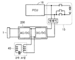
도 10을 참조하여, 본 실시 형태에서는, 충전기(200)에 충전부(1) 및 수전 장치(40)가 접속되어 있다. 또한, 충전기(200)에 배터리(15)가 접속되고, 배터리(15)에는, 충전 제어 유닛(300)이 접속되어 있다. 이와 같이, 본 실시 형태에서는, 접촉 충전인 충전부(1)와 비접촉 수전인 수전 장치(40)가 겸용의 충전기(200)에 접속되어 있다.Referring to Fig. 10, in the present embodiment, the
따라서, 충전기(200)는 충전부(1)로부터 급전되는 전력을, 배터리(15)의 충전 전력으로 변환함과 함께, 수전 장치(40)로부터 수전한 전력을 배터리(15)의 충전 전력으로 변환한다. 이에 의해, 부품 개수의 삭감을 도모할 수 있다.The
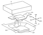
도 11 및 도 12를 참조하여, 리어 플로어 패널(31)에는, 하방을 향하는 오목부 영역(31P)이 형성되어 있다. 이 오목부 영역(31P)의 바닥면 및 경사면을 따르도록, 좌우 방향으로 연장되는 브래킷(210)을 갖고, 이 브래킷(210)에 충전기(200)가 적재된다.11 and 12, the
도 13 및 도 14를 참조하여, 전동 차량(10)의 후방부에 있어서, 배터리(15)는 리어 플로어 패널(31)의 상방에 배치되고, 수전 장치(40)는 리어 플로어 패널(31)의 하방에 배치되고, 평면에서 볼 때, 실시 형태 1의 경우와 마찬가지로, 수전 장치(40)와 배터리(15)는 적어도 일부가 겹치도록 배치되어 있다.13 and 14, the
본 실시 형태에서는, 충전기(200)는 배터리(15)와 리어 플로어 패널(31)의 사이[리어 플로어 패널(31)의 상방]에 위치하고 있지만, 충전기(200)를 리어 플로어 패널(31)과 수전 장치(40) 사이[리어 플로어 패널(31)의 하방]에 위치시키는 것도 가능하다. 또한, 수전 장치(40)의 하방에 대해서는, 상기 실시 형태 1과 마찬가지이다.The charging
또한, 본 실시 형태에서는, 충전기(200)는 브래킷(210)에 적재되어 있지만, 브래킷은 반드시 필수적인 것은 아니다. 충전기(200)의 위치도, 평면에서 볼 때, 배터리(15)와 수전 장치(40) 사이에 있어서, 전부 포함되도록 배치되어 있지만, 일부가 겹치도록 배치되어도 된다. 또한, 충전기(200)와 배터리(15) 사이, 충전기(200)와 브래킷(210) 사이 또는 충전기(200)와 리어 플로어 패널(31) 사이에, 전력 배선, 전력 배선 결합부를 배치해도 된다.In this embodiment, although the
도 14에 도시한 바와 같이, 수전 장치(40)의 후단부(40a)[실드 부재(27S)의 후단부(40a)]는 배터리(15)의 후단부(15a)보다도, 당해 차량의 후방측으로 돌출(거리 CZ1)되도록 배치되어 있다. 또한, 충전기(200)의 후단부(200a)는 배터리(15)의 후단부(15a)보다도, 차량의 전방측에 위치하고 있는 점에서, 수전 장치(40)의 후단부(40a)는 충전기(200)의 후단부(200a)보다도, 당해 차량의 후방측으로 돌출(거리 CZ2)되도록 배치되어 있게 된다. 충전 제어 유닛(300)도 충전기(200)와 마찬가지이다.14, the
이와 같이, 본 실시 형태에 있어서도, 차량의 후방측에 있어서, 후방측으로부터 충돌된 경우에, 크러셔블 존(도 12의 화살표 CZ의 영역)이 규정되고, 배터리(15)는 크러셔블 존보다도 전방측에 배치된다. 따라서, 수전 장치(40)의 일부가, 크러셔블 존측으로 돌출되도록 배치함으로써, 후방측으로부터 충돌된 경우에, 수전 장치(40)를 충격 흡수재로서 사용할 수 있다. 배터리(15) 및 충전기(200) 등의 고압 부품을 보호하는 것이 가능하게 된다.Thus, in this embodiment as well, a crushable zone (the area indicated by the arrow CZ in Fig. 12) is defined when the vehicle collides from the rear side on the rear side of the vehicle, and the
이상, 본 실시 형태에 있어서도, 평면에서 볼 때, 수전 장치(40)의 투영면에 배터리(15)의 투영면의 일부가 적어도 겹치도록, 수전 장치(40)는 리어 플로어 패널(31)을 사이에 두고, 배터리(15)의 하방에 배치되어 있다. 이에 의해, 전동 차량(10)의 한정된 스페이스에, 평면에서 볼 때, 수전 장치(40)를 효율적으로 탑재하는 것을 가능하게 하고 있다.As described above, in the present embodiment, the
또한, 배터리(15)와 수전 장치(40) 사이에 리어 플로어 패널(31)이 위치함으로써, 수전 장치(40)로부터 발열되는 열의 배터리(15)에의 전열을, 리어 플로어 패널(31)에 의해 억제할 수 있다.Further, since the
또한, 수전 장치(40)와 배터리(15)의 거리가 짧아지므로, 수전 장치(40)와 배터리(15) 사이에 배치되는 케이블 WH1, WH2의 배색을 짧게 할 수 있다. 이에 의해, 충전 효율의 향상을 기대하는 것도 가능하게 된다. 또한, 배터리(15), 충전기(200) 및 충전 제어 유닛(300)을 크러셔블 존보다도 차량의 전방측에 배치함으로써, 고압 기기에 대한 안전성을 높여, 케이블 손실(누전, 쇼트)의 발생을 회피할 수 있다.Since the distance between the
또한, 도 15에 도시한 바와 같이, 수전 장치(40)에 충전 제어 유닛(300)을 설치하는 것도 가능하다. 이 경우, 충전 제어 유닛(300)은 도 16에 도시한 바와 같이, 브래킷(210)에 충전 제어 유닛(300)이 고정된다. 충전 제어 유닛(300)으로부터 연장되는 한쪽의 와이어 WH1은, 배터리(15)에 접속된다. 충전 제어 유닛(300)으로부터 연장되는 다른 쪽의 와이어 WH2는, 리어 플로어 패널(31)에 형성된 연통 구멍(31H)을 통과하여, 배터리(15)에 접속된다.15, it is also possible to provide the
또한, 충전 제어 유닛(300)이 브래킷(210)에 고정되어 있는 점에서, 충전 제어 유닛(300)도 수전 장치(40)와 배터리(15) 사이에 배치되어 있다. 충전 제어 유닛(300)을 리어 플로어 패널(31)과 수전 장치(40) 사이[리어 플로어 패널(31)의 하방]에 위치시키는 것도 가능하다.The
또한, 상기 각 실시 형태에서는, 배터리(15) 및 수전 장치(40)를 리어 플로어 패널(31)에 배치한 경우에 대해 설명하고 있지만, 배치 위치는, 전동 차량(10)의 후방부로 한정되지는 않는다.Although the
도 17에 도시한 바와 같이, 상기 각 실시 형태에 나타낸 구성을, 전동 차량(10)의 중앙부에 있어서, 배터리(15) 및 수전 장치(40)를 센터 플로어 패널(32)에 배치하는 것도 가능하다. 또한, 도 18에 도시한 바와 같이, 상기 각 실시 형태에 나타낸 구성을, 전동 차량(10)의 전방부에 있어서, 배터리(15) 및 수전 장치(40)를 엔진 플로어 패널(33)에 배치하는 것도 가능하다.It is also possible to dispose the
또한, 상기 각 실시 형태에서는, 전자기 유도 코일(12, 23)을 포함한 송전 장치 및 수전 장치를 예시하였지만, 전자기 유도 코일을 포함하지 않는 공명형 비접촉 송수전 장치에도 본 발명은 적용 가능하다.In addition, in each of the above-described embodiments, the power transmission device and the power reception device including the electromagnetic induction coils 12 and 23 are exemplified, but the present invention is also applicable to the resonance type non-contact power transmission and reception device that does not include the electromagnetic induction coil.
금회 개시된 실시 형태 및 실시예는 모든 점에서 예시이며, 제한적인 것은 아니라고 생각되어야 한다. 본 발명의 범위는 상기한 설명이 아니라 청구범위에 의해 나타내어지고, 청구범위와 균등한 의미 및 범위 내에서의 모든 변경이 포함되는 것이 의도된다.It should be understood that the presently disclosed embodiments and examples are illustrative in all respects and not restrictive. It is intended that the scope of the invention be indicated by the appended claims rather than the foregoing description, and that all changes that come within the meaning and range of equivalency of the claims are intended to be embraced therein.
1 : 충전부
1A : 급전 커넥터
2 : 급유부
2A : 급유 커넥터
10 : 전동 차량
11, 24, 94, 99 : 공명 코일
12, 23, 92, 97 : 전자기 유도 코일
11a, 12a : 지지 부재
13 : 정류기
14 : DC/DC 컨버터
15 : 배터리
16 : 파워 컨트롤 유닛
17 : 모터 유닛
18 : 차량 ECU
19, 25, 98, 95 : 캐패시터
20 : 외부 급전 장치
21 : 교류 전원
22 : 고주파 전력 드라이버
26 : 제어부
27, 96 : 수전부
27S : 실드 부재
27b : 바닥부
28, 93 : 송전부
29 : 임피던스 조정기
31 : 리어 플로어 패널
31H : 연통 구멍
32 : 센터 플로어 패널
32A, 32B : 사이드 멤버
33 : 엔진 플로어 패널
40, 91 : 수전 장치
40a, 200a : 후단부
41, 90 : 송전 장치
42 : 주차 스페이스
110 : 리어 서스펜션
120 : 연료 탱크
121 : 연료 호스
130 : 머플러
131 : 배기관
160F : 전륜 타이어
160R : 후륜 타이어
200 : 충전기
210 : 브래킷
300 : 충전 제어 유닛1:
1A: Feed connector
2: Supply part
2A: Lubrication connector
10: Electric vehicle
11, 24, 94, 99: resonance coil
12, 23, 92, 97: electromagnetic induction coil
11a, 12a: Support member
13: rectifier
14: DC / DC converter
15: Battery
16: Power control unit
17: Motor unit
18: vehicle ECU
19, 25, 98, 95: capacitors
20: External feeding device
21: AC power source
22: High frequency power driver
26:
27, 96: Handpiece
27S: shield member
27b:
28, 93: All transmission
29: Impedance regulator
31: Rear floor panel
31H: communicating hole
32: Center floor panel
32A, 32B: side member
33: engine floor panel
40, 91: Water receiving device
40a, 200a: rear end portion
41, 90: Transmission device
42: Parking space
110: rear suspension
120: Fuel tank
121: Fuel hose
130: muffler
131: Exhaust pipe
160F: Front tires
160R: rear tire
200: Charger
210: Bracket
300: charge control unit
Claims (13)
외부에 설치된 송전 장치(41)로부터 비접촉으로 전력을 수전하는 수전 장치(40)와,
상기 수전 장치(40)에 접속되는 배터리(15)를 구비하고,
상기 배터리(15)는 상기 플로어 패널(31, 32, 33)의 상방에 배치되고,
상기 수전 장치(40)는 상기 플로어 패널(31, 32, 33)의 하방에 배치되고,
평면에서 볼 때, 상기 수전 장치(40)와 상기 배터리(15)는 적어도 일부가 겹치도록 배치되어 있는, 차량.The floor panels (31, 32, 33)
A power receiving device (40) for receiving electric power from a power transmitting device (41) provided outside in a noncontact manner,
And a battery (15) connected to the water receiving device (40)
The battery (15) is disposed above the floor panels (31, 32, 33)
The water receiving apparatus (40) is disposed below the floor panels (31, 32, 33)
Wherein the power receiving device (40) and the battery (15) are arranged so that at least part of them overlap.
충전기(200)를 더 구비하고,
상기 충전기(200)는 상기 수전 장치(40)와 상기 배터리(15) 사이에 배치되어 있는, 차량.The method according to claim 1,
Further comprising a charger (200)
Wherein the charger (200) is disposed between the power reception device (40) and the battery (15).
외부에 설치된 급전 커넥터(1A)에 접속되는 충전부(1)를 더 구비하고,
상기 충전기(200)는 상기 충전부(1)로부터 급전되는 전력을, 상기 배터리(15)의 충전 전력으로 변환함과 함께, 상기 수전 장치(40)로부터 수전한 전력을 상기 배터리(15)의 충전 전력으로 변환하는, 차량.3. The method of claim 2,
Further comprising a charging section (1) connected to an external power supply connector (1A)
The charger 200 converts the power supplied from the charging unit 1 into the charging power of the battery 15 and converts the power received from the power receiving apparatus 40 to the charging power of the battery 15 .
충전 제어 유닛(300)을 더 구비하고,
상기 충전 제어 유닛(300)은 상기 수전 장치(40)와 상기 배터리(15) 사이에 배치되는, 차량.The method according to claim 2 or 3,
Further comprising a charge control unit (300)
Wherein the charge control unit (300) is disposed between the power reception device (40) and the battery (15).
상기 수전 장치(40)의 후단부(40a)는 상기 배터리(15)의 후단부(15a)보다도, 당해 차량의 후방측으로 돌출되도록 배치되어 있는, 차량.5. The method according to any one of claims 1 to 4,
Wherein a rear end portion (40a) of the water receiving apparatus (40) is arranged to protrude from the rear side of the vehicle (15a) more than a rear end portion (15a) of the battery (15).
상기 송전 장치(41)는 비접촉으로 전력을 상기 수전 장치(40)에 송전하는 송전부(28)를 포함하고,
상기 수전 장치(40)는 상기 송전부(28)로부터 비접촉으로 전력을 수전하는 수전부(27)를 포함하고,
상기 송전부(28)의 고유 주파수와 상기 수전부(27)의 고유 주파수의 차는, 상기 수전부(27)의 고유 주파수의 10% 이하인, 차량.The method according to claim 1,
The power transmission device (41) includes a power transmission part (28) for transmitting power to the power reception device (40) in a noncontact manner,
The power reception device (40) includes a power receiver (27) for receiving electric power from the power transmission part (28) in a noncontact manner,
Wherein a difference between a natural frequency of the power transmitting part (28) and a natural frequency of the power receiver (27) is 10% or less of a natural frequency of the power receiver (27).
상기 송전 장치(41)는 비접촉으로 전력을 상기 수전 장치(40)에 송전하는 송전부(28)를 포함하고,
상기 수전 장치(40)는 상기 송전부(28)로부터 비접촉으로 전력을 수전하는 수전부(27)를 포함하고,
상기 수전부(27)와 상기 송전부(28)의 결합 계수는, 0.1 이하인, 차량.The method according to claim 1,
The power transmission device (41) includes a power transmission part (28) for transmitting power to the power reception device (40) in a noncontact manner,
The power reception device (40) includes a power receiver (27) for receiving electric power from the power transmission part (28) in a noncontact manner,
Wherein a coupling coefficient between the power receiver (27) and the power transmitting part (28) is 0.1 or less.
상기 송전 장치(41)는 비접촉으로 전력을 상기 수전 장치(40)에 송전하는 송전부(28)를 포함하고,
상기 수전 장치(40)는 상기 송전부(28)로부터 비접촉으로 전력을 수전하는 수전부(27)를 포함하고,
상기 수전부(27)는 상기 수전부(27)와 상기 송전부(28)의 사이에 형성되고, 또한 특정한 주파수로 진동하는 자계와, 상기 수전부(27)와 상기 송전부(28)의 사이에 형성되고, 또한 특정한 주파수로 진동하는 전계 중 적어도 한쪽을 통하여 상기 송전부(28)로부터 전력을 수전하는, 차량.The method according to claim 1,
The power transmission device (41) includes a power transmission part (28) for transmitting power to the power reception device (40) in a noncontact manner,
The power reception device (40) includes a power receiver (27) for receiving electric power from the power transmission part (28) in a noncontact manner,
The power receiver 27 includes a magnetic field formed between the power receiver 27 and the power transmitter 28 and vibrating at a specific frequency and a magnetic field generated between the power receiver 27 and the power transmitter 28 And receives electric power from the power transmitting section (28) through at least one of an electric field oscillating at a specific frequency.
플로어 패널(31, 32, 33), 상기 송전 장치(41)로부터 수전하는 수전 장치(40) 및 상기 수전 장치(40)에 접속되는 배터리(15)를 포함하는 차량(10)을 구비하고,
상기 배터리(15)는 상기 플로어 패널(31, 32, 33)의 상방에 배치되고,
상기 수전 장치(40)는 상기 플로어 패널(31, 32, 33)의 하방에 배치되고,
평면에서 볼 때, 상기 수전 장치(40)와 상기 배터리(15)는 적어도 일부가 겹치도록 배치되어 있는, 전력 전송 시스템.A power transmission device 41 for transmitting electric power in a noncontact manner,
A vehicle (10) comprising floor panels (31, 32, 33), a power receiving device (40) for receiving power from the power transmission device (41) and a battery (15) connected to the power receiving device (40)
The battery (15) is disposed above the floor panels (31, 32, 33)
The water receiving apparatus (40) is disposed below the floor panels (31, 32, 33)
The power reception device (40) and the battery (15) are arranged so that at least a part thereof overlaps.
상기 차량(10)은 충전기(200)를 더 구비하고,
상기 충전기(200)는 상기 수전 장치(40)와 상기 배터리(15) 사이에 배치되는, 전력 전송 시스템.10. The method of claim 9,
The vehicle 10 further includes a charger 200,
Wherein the charger (200) is disposed between the power reception device (40) and the battery (15).
상기 차량(10)은 외부에 설치된 급전 커넥터(1A)에 접속되는 충전부(1)를 더 구비하고,
상기 충전기(200)는 상기 충전부(1)로부터 급전되는 전력을, 상기 배터리(15)의 충전 전력으로 변환함과 함께, 상기 수전 장치(40)로부터 수전한 전력을 상기 배터리(15)의 충전 전력으로 변환하는, 전력 전송 시스템.11. The method of claim 10,
The vehicle (10) further includes a charging section (1) connected to an external power supply connector (1A)
The charger 200 converts the power supplied from the charging unit 1 into the charging power of the battery 15 and converts the power received from the power receiving apparatus 40 to the charging power of the battery 15 To a power transmission system.
상기 차량(10)은 충전 제어 유닛(300)을 더 구비하고,
상기 충전 제어 유닛(300)은 상기 수전 장치(40)와 상기 배터리(15) 사이에 배치되는, 전력 전송 시스템.The method according to claim 10 or 11,
The vehicle 10 further includes a charge control unit 300,
Wherein the charge control unit (300) is disposed between the power reception device (40) and the battery (15).
상기 수전 장치(40)의 후단부(40a)는 상기 배터리(15)의 후단부(15a)보다도, 당해 차량의 후방측으로 돌출되도록 배치되어 있는, 전력 전송 시스템.13. The method according to any one of claims 9 to 12,
Wherein a rear end portion (40a) of the power reception device (40) is arranged so as to protrude from the rear side of the vehicle (15a) more than a rear end portion (15a) of the battery (15).
Applications Claiming Priority (1)
| Application Number | Priority Date | Filing Date | Title |
|---|---|---|---|
| PCT/JP2011/076860 WO2013076804A1 (en) | 2011-11-22 | 2011-11-22 | Vehicle and power transmission system |
Publications (1)
| Publication Number | Publication Date |
|---|---|
| KR20140099276A true KR20140099276A (en) | 2014-08-11 |
Family
ID=48469285
Family Applications (1)
| Application Number | Title | Priority Date | Filing Date |
|---|---|---|---|
| KR1020147016692A KR20140099276A (en) | 2011-11-22 | 2011-11-22 | Vehicle and power transmission system |
Country Status (6)
| Country | Link |
|---|---|
| US (1) | US9969281B2 (en) |
| EP (1) | EP2783890B1 (en) |
| JP (1) | JP5825356B2 (en) |
| KR (1) | KR20140099276A (en) |
| CN (1) | CN103946045B (en) |
| WO (1) | WO2013076804A1 (en) |
Families Citing this family (23)
| Publication number | Priority date | Publication date | Assignee | Title |
|---|---|---|---|---|
| CN107415764B (en) * | 2012-05-09 | 2020-09-29 | 丰田自动车株式会社 | Vehicle with a steering wheel |
| GB2512862A (en) | 2013-04-09 | 2014-10-15 | Bombardier Transp Gmbh | Receiving device with coil of electric line for receiving a magnetic field and for producing electric energy by magnetic induction |
| GB2512855A (en) * | 2013-04-09 | 2014-10-15 | Bombardier Transp Gmbh | Receiving device for receiving a magnetic field and for producing electric energy by magnetic induction |
| GB2516854A (en) | 2013-08-01 | 2015-02-11 | Bombardier Transp Gmbh | Carrying device and a receiving device |
| JP6003853B2 (en) * | 2013-09-11 | 2016-10-05 | トヨタ自動車株式会社 | vehicle |
| EP3356177A1 (en) * | 2015-09-30 | 2018-08-08 | Volvo Truck Corporation | A charging device for a vehicle |
| JP6292205B2 (en) | 2015-10-20 | 2018-03-14 | トヨタ自動車株式会社 | Vehicle underfloor structure |
| JP6556084B2 (en) * | 2016-03-29 | 2019-08-07 | 株式会社クボタ | Non-contact charging system and electric mower for electric work vehicle |
| US10029551B2 (en) | 2015-11-16 | 2018-07-24 | Kubota Corporation | Electric work vehicle, battery pack for electric work vehicle and contactless charging system |
| US10538166B2 (en) | 2016-03-29 | 2020-01-21 | Kubota Corporation | Portable charger device, contactless charger system for electric work vehicle and electric grass mower machine |
| CN105845859B (en) * | 2016-03-31 | 2018-09-28 | 北京长城华冠汽车科技股份有限公司 | A kind of battery cabinet frame and the automobile for including the battery cabinet frame |
| EP3466743A4 (en) * | 2016-05-31 | 2020-01-01 | Nidec Corporation | Mobile body and mobile body system |
| JP6379135B2 (en) | 2016-06-23 | 2018-08-22 | 本田技研工業株式会社 | Power supply and transportation equipment |
| JP6460068B2 (en) * | 2016-09-05 | 2019-01-30 | トヨタ自動車株式会社 | vehicle |
| JP6496288B2 (en) * | 2016-09-13 | 2019-04-03 | 本田技研工業株式会社 | Vehicle charging unit arrangement structure |
| JP6421807B2 (en) * | 2016-10-03 | 2018-11-14 | トヨタ自動車株式会社 | vehicle |
| JP6400061B2 (en) | 2016-10-21 | 2018-10-03 | 株式会社Subaru | Electric vehicle |
| MX2019008842A (en) * | 2017-01-30 | 2019-09-09 | Nissan Motor | Vehicle-mounting structure for contactless power reception device. |
| JP6819476B2 (en) * | 2017-06-16 | 2021-01-27 | トヨタ自動車株式会社 | Vehicle front structure |
| JP6794949B2 (en) * | 2017-07-13 | 2020-12-02 | トヨタ自動車株式会社 | Vehicle front structure |
| DE102018203263A1 (en) * | 2018-03-06 | 2019-09-12 | Audi Ag | Charging device for a motor vehicle |
| DE102019212277A1 (en) * | 2018-11-05 | 2020-05-07 | Mahle International Gmbh | Induction charger |
| JP7462896B2 (en) * | 2019-10-09 | 2024-04-08 | 国立大学法人 東京大学 | Wireless power receiving system, mobile body, and wheel |
Family Cites Families (25)
| Publication number | Priority date | Publication date | Assignee | Title |
|---|---|---|---|---|
| JPH082125B2 (en) | 1991-12-26 | 1996-01-10 | 株式会社明工社 | Electric vehicle power supply device |
| JPH0686470A (en) * | 1992-09-03 | 1994-03-25 | Nippon Yusoki Co Ltd | Battery charging apparatus for forklift |
| US5617003A (en) * | 1995-03-24 | 1997-04-01 | Kabushiki Kaisha Toyoda Jidoshokki Seisakusho | Method and apparatus for charging a battery of an electric vehicle |
| US5703461A (en) * | 1995-06-28 | 1997-12-30 | Kabushiki Kaisha Toyoda Jidoshokki Seisakusho | Inductive coupler for electric vehicle charger |
| JP2001177916A (en) | 1999-12-10 | 2001-06-29 | Toyota Motor Corp | Energy-supplying apparatus |
| JP3851124B2 (en) * | 2001-07-31 | 2006-11-29 | 三洋電機株式会社 | Automotive power supply and automobile equipped with this power supply |
| JP2003274569A (en) | 2002-03-15 | 2003-09-26 | Konica Corp | Electronic apparatus |
| US7825543B2 (en) | 2005-07-12 | 2010-11-02 | Massachusetts Institute Of Technology | Wireless energy transfer |
| US7741734B2 (en) | 2005-07-12 | 2010-06-22 | Massachusetts Institute Of Technology | Wireless non-radiative energy transfer |
| JP4222355B2 (en) * | 2005-09-29 | 2009-02-12 | トヨタ自動車株式会社 | PARKING ASSISTANCE DEVICE AND POWER TRANSFER METHOD BETWEEN VEHICLE AND GROUND EQUIPMENT |
| JP4748010B2 (en) * | 2006-09-19 | 2011-08-17 | トヨタ自動車株式会社 | Power supply |
| CN103384095B (en) | 2007-03-27 | 2016-05-18 | 麻省理工学院 | For the equipment of wireless energy transfer |
| CN102177042B (en) * | 2008-10-09 | 2013-10-23 | 丰田自动车株式会社 | Non-contact power transmission device and vehicle having non-contact power transmission device |
| JP5351499B2 (en) * | 2008-11-28 | 2013-11-27 | 長野日本無線株式会社 | Contactless power transmission system |
| JP4909446B2 (en) * | 2009-05-14 | 2012-04-04 | トヨタ自動車株式会社 | Vehicle charging device |
| JP5051257B2 (en) * | 2010-03-16 | 2012-10-17 | トヨタ自動車株式会社 | vehicle |
| JP5691458B2 (en) * | 2010-03-31 | 2015-04-01 | 日産自動車株式会社 | Non-contact power feeding apparatus and non-contact power feeding method |
| JP5146488B2 (en) * | 2010-05-26 | 2013-02-20 | トヨタ自動車株式会社 | Power feeding system and vehicle |
| JP5348183B2 (en) * | 2010-08-18 | 2013-11-20 | 三洋電機株式会社 | Battery built-in equipment and charger |
| JP5577986B2 (en) * | 2010-09-22 | 2014-08-27 | 株式会社豊田自動織機 | Power supply device and in-vehicle power supply device |
| US8988042B2 (en) * | 2011-08-25 | 2015-03-24 | Toyota Jidosha Kabushiki Kaisha | Vehicle, charging system and control method for vehicle |
| EP2747245A1 (en) * | 2011-09-21 | 2014-06-25 | Toyota Jidosha Kabushiki Kaisha | Contactless power transmission device, contactless power receiving device and contactless power transceiver system |
| WO2013042243A1 (en) * | 2011-09-22 | 2013-03-28 | トヨタ自動車株式会社 | Vehicle power supply system |
| US9673664B2 (en) * | 2011-10-27 | 2017-06-06 | Toyota Jidosha Kabushiki Kaisha | Wireless power reception apparatus, wireless power transmission apparatus, and wireless power transmission and reception system |
| JP5168430B1 (en) * | 2011-11-17 | 2013-03-21 | トヨタ自動車株式会社 | Vehicle, power supply system, power supply device, and vehicle control method |
-
2011
- 2011-11-22 WO PCT/JP2011/076860 patent/WO2013076804A1/en active Application Filing
- 2011-11-22 KR KR1020147016692A patent/KR20140099276A/en active Search and Examination
- 2011-11-22 JP JP2013545681A patent/JP5825356B2/en active Active
- 2011-11-22 CN CN201180074976.8A patent/CN103946045B/en not_active Expired - Fee Related
- 2011-11-22 EP EP11876115.4A patent/EP2783890B1/en active Active
- 2011-11-22 US US14/357,695 patent/US9969281B2/en active Active
Also Published As
| Publication number | Publication date |
|---|---|
| EP2783890B1 (en) | 2020-02-12 |
| CN103946045A (en) | 2014-07-23 |
| US9969281B2 (en) | 2018-05-15 |
| CN103946045B (en) | 2016-08-24 |
| EP2783890A1 (en) | 2014-10-01 |
| EP2783890A4 (en) | 2015-11-18 |
| US20140320078A1 (en) | 2014-10-30 |
| JP5825356B2 (en) | 2015-12-02 |
| JPWO2013076804A1 (en) | 2015-04-27 |
| WO2013076804A1 (en) | 2013-05-30 |
Similar Documents
| Publication | Publication Date | Title |
|---|---|---|
| JP5825356B2 (en) | Vehicle and power transmission system | |
| US10960770B2 (en) | Vehicle | |
| JP5083413B2 (en) | Electric vehicle | |
| JP5776703B2 (en) | Vehicle and external power supply device | |
| EP2783891B1 (en) | Vehicle | |
| EP3269585B1 (en) | Vehicle comprising contactless power reception unit | |
| WO2013168241A1 (en) | Vehicle | |
| JP5718830B2 (en) | vehicle | |
| US20150102684A1 (en) | Vehicle capable of contactlessly receiving electric power | |
| EP2858078A1 (en) | Power reception device, power transmission device, and vehicle | |
| JP6508272B2 (en) | vehicle |
Legal Events
| Date | Code | Title | Description |
|---|---|---|---|
| A201 | Request for examination | ||
| E902 | Notification of reason for refusal | ||
| AMND | Amendment | ||
| E601 | Decision to refuse application | ||
| AMND | Amendment | ||
| J201 | Request for trial against refusal decision | ||
| J301 | Trial decision |
Free format text: TRIAL NUMBER: 2016101002609; TRIAL DECISION FOR APPEAL AGAINST DECISION TO DECLINE REFUSAL REQUESTED 20160502 Effective date: 20170425 |