KR20140090541A - Washing Machine and Manufacturing Method of Door - Google Patents
Washing Machine and Manufacturing Method of Door Download PDFInfo
- Publication number
- KR20140090541A KR20140090541A KR1020130091715A KR20130091715A KR20140090541A KR 20140090541 A KR20140090541 A KR 20140090541A KR 1020130091715 A KR1020130091715 A KR 1020130091715A KR 20130091715 A KR20130091715 A KR 20130091715A KR 20140090541 A KR20140090541 A KR 20140090541A
- Authority
- KR
- South Korea
- Prior art keywords
- door
- door cover
- glass
- cabinet
- coupled
- Prior art date
Links
Images


Classifications
-
- D—TEXTILES; PAPER
- D06—TREATMENT OF TEXTILES OR THE LIKE; LAUNDERING; FLEXIBLE MATERIALS NOT OTHERWISE PROVIDED FOR
- D06F—LAUNDERING, DRYING, IRONING, PRESSING OR FOLDING TEXTILE ARTICLES
- D06F39/00—Details of washing machines not specific to a single type of machines covered by groups D06F9/00 - D06F27/00
- D06F39/12—Casings; Tubs
- D06F39/14—Doors or covers; Securing means therefor
-
- D—TEXTILES; PAPER
- D06—TREATMENT OF TEXTILES OR THE LIKE; LAUNDERING; FLEXIBLE MATERIALS NOT OTHERWISE PROVIDED FOR
- D06F—LAUNDERING, DRYING, IRONING, PRESSING OR FOLDING TEXTILE ARTICLES
- D06F37/00—Details specific to washing machines covered by groups D06F21/00 - D06F25/00
- D06F37/02—Rotary receptacles, e.g. drums
- D06F37/04—Rotary receptacles, e.g. drums adapted for rotation or oscillation about a horizontal or inclined axis
- D06F37/10—Doors; Securing means therefor
-
- D—TEXTILES; PAPER
- D06—TREATMENT OF TEXTILES OR THE LIKE; LAUNDERING; FLEXIBLE MATERIALS NOT OTHERWISE PROVIDED FOR
- D06F—LAUNDERING, DRYING, IRONING, PRESSING OR FOLDING TEXTILE ARTICLES
- D06F37/00—Details specific to washing machines covered by groups D06F21/00 - D06F25/00
- D06F37/26—Casings; Tubs
- D06F37/261—Tubs made by a specially selected manufacturing process or characterised by their assembly from elements
- D06F37/262—Tubs made by a specially selected manufacturing process or characterised by their assembly from elements made of plastic material, e.g. by injection moulding
-
- D—TEXTILES; PAPER
- D06—TREATMENT OF TEXTILES OR THE LIKE; LAUNDERING; FLEXIBLE MATERIALS NOT OTHERWISE PROVIDED FOR
- D06F—LAUNDERING, DRYING, IRONING, PRESSING OR FOLDING TEXTILE ARTICLES
- D06F37/00—Details specific to washing machines covered by groups D06F21/00 - D06F25/00
- D06F37/26—Casings; Tubs
- D06F37/264—Tubs provided with reinforcing structures, e.g. ribs, inserts, braces
-
- D—TEXTILES; PAPER
- D06—TREATMENT OF TEXTILES OR THE LIKE; LAUNDERING; FLEXIBLE MATERIALS NOT OTHERWISE PROVIDED FOR
- D06F—LAUNDERING, DRYING, IRONING, PRESSING OR FOLDING TEXTILE ARTICLES
- D06F37/00—Details specific to washing machines covered by groups D06F21/00 - D06F25/00
- D06F37/26—Casings; Tubs
- D06F37/28—Doors; Security means therefor
-
- E—FIXED CONSTRUCTIONS
- E05—LOCKS; KEYS; WINDOW OR DOOR FITTINGS; SAFES
- E05Y—INDEXING SCHEME RELATING TO HINGES OR OTHER SUSPENSION DEVICES FOR DOORS, WINDOWS OR WINGS AND DEVICES FOR MOVING WINGS INTO OPEN OR CLOSED POSITION, CHECKS FOR WINGS AND WING FITTINGS NOT OTHERWISE PROVIDED FOR, CONCERNED WITH THE FUNCTIONING OF THE WING
- E05Y2900/00—Application of doors, windows, wings or fittings thereof
- E05Y2900/30—Application of doors, windows, wings or fittings thereof for domestic appliances
- E05Y2900/312—Application of doors, windows, wings or fittings thereof for domestic appliances for washing machines
Abstract
Description
본 발명은 세탁기 및 세탁기의 도어에 관한 것으로, 보다 상세하게는 도어의 제조시 공정을 간편히 할 수 있도록 구조 및 제조방법을 개선한 세탁기 및 세탁기 도어의 제조방법에 관한 것이다. BACKGROUND OF THE INVENTION 1. Field of the Invention The present invention relates to a door of a washing machine and a washing machine, and more particularly, to a washing machine and a method of manufacturing a door of a washing machine improved in structure and manufacturing method so as to simplify a process of manufacturing a door.
세탁기는 전력을 이용하여 의류를 세탁하는 기계로서, 일 반적으로 세탁 방식에 따라 펄세이터 방식과 드럼 방식으로 구분된다. 드럼 방식의 경우, 캐비닛과, 캐비닛 내부에 세탁수를 수용하도록 마련되는 터브와, 터브의 내부에 회전 가능하게 설치되는 드럼와, 드럼을 회전시키기 위한 모터와, 개구부를 개폐하는 도어를 포함한다 A washing machine is a machine for washing clothes using electric power. In general, it is divided into a pulsator type and a drum type according to a washing type. The drum type includes a cabinet, a tub provided to receive wash water in the cabinet, a drum rotatably installed in the tub, a motor for rotating the drum, and a door for opening and closing the opening
드럼 방식의 경우에는 낙차에 의해 세탁이 이루어지도록 한다. 내조 내에는 세탁물을 상측으로 끌어올리기 위한 리프터가 배치된다.In the case of the drum type, washing is carried out by the dropping. In the inner tank, a lifter for lifting the laundry upward is disposed.
도어는 외형을 이루는 도어 커버와, 세탁기 내부로 돌출되는 글라스와, 글라스를 고정시키는 글라스 홀더를 포함한다. The door includes a door cover which forms an outer shape, a glass protruding into the washing machine, and a glass holder for fixing the glass.
근래에는 도어 커버에는 디자인상의 미려함과 캐비닛과의 구분을 위하여 장식적인 요소를 부가한다. 종래에는 이러한 장식적 요소를 위하여 칼라 스프레이, 크롬 도금, 본딩 등과 같은 후가공을 가하였으며, 이는 폐수 빛 공해 물질을 발생시켜 친환경적이지 않으며 후가공에 따라 제조비용이 상승한다는 문제점이 있었다.In recent years, decorative elements are added to the door cover to distinguish the design from the cabinet. Conventionally, post-processing such as color spraying, chrome plating, bonding or the like has been applied to such decorative elements, which is not environmentally friendly due to the generation of wastewater light pollutants, and the manufacturing cost increases according to the post-processing.
본 발명의 일 측면은 도어 커버가 이중사출을 통해 형성되는 도어를 포함하는 세탁기를 제공한다. One aspect of the present invention provides a washing machine including a door formed by a double injection of a door cover.
본 발명의 일 측면은 외관을 형성하며 투입구를 가지는 캐비닛, 상기 캐비닛 내측에 위치하며 세탁수를 수용 가능한 외조, 상기 외조의 내측에 위치하며 세탁물을 수용 가능한 내조, 상기 투입구를 개폐하는 도어를 포함하며, 상기 도어는, 중심에 마련되는 개구와, 외측에 위치하며 빛이 통과되도록 투명한 소재로 마련되는 제1부분과, 상기 제1부분과 동심원 형태로 마련되도록 상기 제1부분의 내측에 위치하며 상기 제1부분을 통해 투영되도록 불투명한 소재로 상기 제1부분과 일체로 성형되는 제2부분을 포함하는 도어커버를 포함하며, 상기 제1부분은, 상기 제2부분이 투영될 수 있도록 상기 제2부분과 결합된 제1영역과, 상기 제2부분과 결합되지 않은 제2영역을 포함하며, 상기 제2영역은 상기 제1영역보다 상기 개구의 중심에서 멀리 위치하는 것을 특징으로 하는 세탁기를 제공한다. One aspect of the present invention is a washing machine comprising a cabinet having an inlet and an inlet, an outer tub located inside the cabinet and capable of receiving washing water, an inner tub located inside the tub, a door for opening and closing the inlet, The door includes an opening provided at the center, a first portion located on the outer side and made of a transparent material through which light passes, and a second portion located on the inner side of the first portion so as to be concentric with the first portion, And a door cover including a second portion integrally molded with the first portion, the second portion being opaque to be projected through the first portion, wherein the first portion includes a second portion, And a second region that is not coupled to the second portion, wherein the second region is located farther from the center of the opening than the first region The washing machine is provided as a gong.
상기 제1영역은 소정의 각도로 경사지게 형성된 경사부를 포함할 수 있다. The first region may include an inclined portion that is inclined at a predetermined angle.
상기 제1부분과 상기 제2부분 중 적어도 하나에는 표면이 돌출된 돌출부와, 표면이 파인 오목부가 교대로 형성되는 요철부가 형성될 수 있다. At least one of the first portion and the second portion may be provided with a protrusion protruding from the surface thereof and a concavity and convexity portion formed by alternately forming concave portions on the surface thereof.
상기 제1부분과 상기 제2부분의 사이에서 빛의 산란이 일어나도록 상기 제1부분과 상기 제2부분의 적어도 일부분이 이격되도록 갭이 마련될 수 있다. A gap may be provided such that at least a portion of the first portion and the second portion are spaced such that scattering of light occurs between the first portion and the second portion.
상기 도어 커버의 후면에 결합하는 글라스 홀더를 더 포함할 수 있다. And a glass holder coupled to a rear surface of the door cover.
상기 도어 커버와 상기 글라스 홀더의 사이에 결합되는 글라스를 더 포함할 수 있다. And a glass coupled between the door cover and the glass holder.
상기 제1부분은 폴리메틸메타크릴레이트(PMMA; polymethyl metacrylate), 폴리카보네으트(PC; Polycrbonate) 중 적어도 어느 하나로 이루어질 수 있다. The first portion may be formed of at least one of polymethyl methacrylate (PMMA) and polycarbonate (PC).
상기 제2부분은 아크릴로나이트릴-부타다이엔-스타이렌 수지(ABS;acrylonitrile butadiene styrene copolymer)로 이루어질 수 있다.The second portion may be made of acrylonitrile butadiene styrene copolymer (ABS).
본 발명의 다른 일 측면은 외관을 형성하며 투입구를 가지는 캐비닛, 상기 캐비닛 내측에 위치하며 세탁수를 수용 가능한 외조, 상기 외조의 내측에 위치하며 세탁물을 수용 가능한 내조, 상기 투입구를 개폐하는 도어를 포함하며, 상기 도어는 상기 도어 커버의 적어도 일부분에 투명한 소재로 마련되는 제1부분과, 적어도 일부분에 불투명한 소재로 마련되는 제2부분을 포함하며, 상기 제1부분은 상기 제2부분과 결합되는 제1영역과 상기 제2부분과 결합되지 않은 제2영역을 포함하며, 상기 제2영역은 빛의 산란으로 인해 메탈 색상을 띠는 것을 특징으로 하는 세탁기를 제공한다. According to another aspect of the present invention, there is provided a cabinet including a cabinet having an inlet and an inlet, an outer tub located inside the cabinet and capable of receiving wash water, an inner tub located inside the tub, a door for opening and closing the inlet, Wherein the door includes a first portion provided in at least a portion of the door cover with a transparent material and a second portion provided in at least a portion opaque material, the first portion being coupled to the second portion And a second region that is not coupled to the second portion, the second region having a metal color due to light scattering.
상기 제1부분과 상기 제2부분은 상기 도어 커버의 테두리를 따라 형성되며, 상기 제1부분이 외측에 위치하며, 상기 제1부분의 내측에 상기 제2부분이 위치할 수 있다. The first portion and the second portion are formed along the rim of the door cover, and the first portion is located on the outer side and the second portion is located on the inner side of the first portion.
상기 제1부분과 상기 제2부분 사이에는 빛의 산란을 위한 갭이 형성될 수 있다. A gap for light scattering may be formed between the first portion and the second portion.
상기 제1부분은 상기 세탁기의 내측 방향으로 40° 내지 50°경사지게 형성된 경사부를 포함할 수 있다. The first portion may include an inclined portion inclined at an angle of 40 ° to 50 ° with respect to the inward direction of the washer.
상기 제1부분은 내면이 돌출된 돌출부와 내면이 상기 도어 커버며 외측 방향으로 파인 오목부를 포함하는 요철부를 더 포함할 수 있다. The first portion may further include a protruding portion having an inner surface protruding and a recessed portion including an inner surface of the door cover and a depressed portion depressed in an outward direction.
본 발명의 또 다른 일 측면은 외관을 형성하며 투입구를 가지는 캐비닛. 상기 캐비닛 내측에 위치하며 세탁수를 수용 가능한 터브, 상기 터브의 내측에 위치하며 세탁물을 수용 가능한 드럼, 상기 투입구를 개폐하는 도어, 상기 도어는 적어도 일부분에 마련되는 제1부분과, 상기 제1부분과 일체로 사출성형되는 제2부분을 포함하며, 상기 제1부분과 상기 제2부분 중 적어도 하나의 일측에 위치하며, 빛의 투과율 차이를 발생시켜 상기 캐비닛과 상기 도어 어셈블리의 외관상 차이가 시각적으로 인삭될 수 있도록 마련되는 경사부를 포함하는 것을 특징으로 하는 세탁기를 제공한다. Another aspect of the present invention is a cabinet forming an appearance and having an inlet. A drum disposed inside the cabinet and capable of receiving laundry, a drum disposed inside the tub and capable of receiving laundry, a door opening and closing the inlet, a first portion provided at least at a portion of the door, And a second portion that is integrally injection-molded and is disposed at one side of at least one of the first portion and the second portion to generate a difference in transmittance of light so that the difference in appearance between the cabinet and the door assembly is visually And an inclined portion provided so as to be rotatable.
상기 제1부분의 내측에 상기 제2부분이 위치할 수 있다. And the second portion may be located inside the first portion.
상기 경사부는 상기 내측 방향으로 경사지게 마련될 수 있다. The inclined portion may be inclined in the inward direction.
상기 도어와 접촉하는 상기 캐비닛의 적어도 일부분은 내측으로 함몰된 오목부를 더 포함하며, 상기 오목부는 상기 글라스 홀더와 접촉할 수 있다. At least a portion of the cabinet in contact with the door further includes an inwardly recessed recess, which can contact the glass holder.
본 발명의 또 다른 일 측면은 세탁기의 투입구를 개폐하는 도어의 제조방법에 있어서, 빛이 통과되도록 구성되는 제1부분을 1차 사출 성형하고, 상기 제1부분의 내측에 위치하며 상기 제1부분을 통해 적어도 일부분이 투영되는 제2부분을 2차 사출 성형하는 것을 포함하는 것을 특징으로 하는 세탁기의 도어의 제조방법을 제공한다. According to another aspect of the present invention, there is provided a door manufacturing method for opening and closing a door of a washing machine, the door comprising: a first part that is configured to pass light therethrough; Wherein the second portion is at least partially projected through the first portion and the second portion.
상기 제1부분은 투명한 소재로 이루어지며, 상기 제2부분은 유색의 불투명한 소재로 이루어질 수 있다. The first portion may be made of a transparent material, and the second portion may be made of a color opaque material.
상기 제1부분의 1차 사출 성형 후, 소정 시간동안 냉각되는 과정을 더 포함할 수 있다.And cooling the first portion after the first injection molding for a predetermined period of time.
상기 제2부분의 2차 사출 성형 후, 소정 시간동안 냉각되는 과정을 더 포함할 수 있다. And cooling the second portion for a predetermined time after the secondary injection molding.
상기 제1부분은 소정 각도로 경사지게 형성된 경사부를 포함할 수 있다. The first portion may include an inclined portion formed to be inclined at a predetermined angle.
상기 제1부분과 상기 제2부분은 상기 도어의 외측에 결합되는 도어 커버에 마련될 수 있다.The first portion and the second portion may be provided on a door cover coupled to the outside of the door.
상기 도어 커버의 사출 성형 후, 글라스가 결합되는 과정을 더 포함할 수 있다. The method may further include a step of bonding the glass after the injection molding of the door cover.
상기 글라스의 결합 후에, 상기 글라스를 고정시키기 위한 글라스 홀더가 결합되는 과정을 더 포함할 수 있다. And a glass holder for fixing the glass after the bonding of the glass.
본 발명의 일 실시예에 따르면, 후가공이 필요 없기 때문에 도어의 제조 비용을 줄 일 수 있으며, 친환경적임과 동시에 디자인적 효과를 누릴 수 있다는 이점이 있다. According to the embodiment of the present invention, since the post processing is not necessary, the manufacturing cost of the door can be reduced, and it is advantageous that the design effect can be enjoyed while being eco-friendly.
도 1은 본 발명의 일 실시예에 따른 세탁기의 사시도이다.
도 2는 본 발명의 일 실시예에 따른 세탁기의 도어가 개방된 상태를 도시한 사시도이다.
도 3은 본 발명의 일 실시예에 따른 세탁기의 단면도이다.
도 4a는 본 발명의 일 실시예에 따른 도어의 정면을 도시한 도면이다.
도 4b는 본 발명의 일 실시예에 따른 도어 커버의 후면을 도시한 도면이다.
도 5는 본 발명의 일 실시예에 따른 도어를 분해하여 도시한 분해도이다.
도 6은 본 발명의 일 실시예에 따른 도어 커버의 단면을 도시한 단면도이다.
도 7은 본 발명의 일 실시예에 따른 도어 커버와 홀더 글라스의 결합 단면을 도시한 단면도이다.
도 8은 본 발명의 다른 실시예에 따른 도어 커버와 홀더 글라스의 결합 단면을 도시한 단면도이다.
도 9은 본 발명의 또 다른 실시예에 따른 도어 커버와 홀더 글라스의 결합 단면을 도시한 단면도이다.
도 10은 본 발명의 또 다른 실시예에 따른 도어 커버와 홀더 글라스의 결합 단면을 도시한 도면이다.
도 11은 본 발명의 또 다른 실시예에 따른 도어를 분해하여 도시한 분해도이다.
도 12a 내지 도 12c는 본 발명의 다른 실시예에 따른 도어 커버가 사출 성형되는 과정을 간략히 도시한 도면이다.
도 13은 본 발명의 일 실시예에 따른 노브를 분해하여 도시한 도면이다.
도 14는 본 발명의 또 다른 실시예에 따른 홀더 글라스를 도시한 도면이다.
도 15은 본 발명의 또 다른 실시예에 따른 도어 커버를 도시한 도면이다.
도 16는 본 발명의 또 다른 실시예에 따른 홀더 글라스와 도어 커버가 결합된 상태의 단면을 도시한 도면이다. 1 is a perspective view of a washing machine according to an embodiment of the present invention.
2 is a perspective view illustrating a state in which a door of a washing machine is opened according to an embodiment of the present invention.
3 is a sectional view of a washing machine according to an embodiment of the present invention.
4A is a front view of a door according to an embodiment of the present invention.
4B is a rear view of a door cover according to an embodiment of the present invention.
5 is an exploded view illustrating a door according to an embodiment of the present invention.
6 is a cross-sectional view of a door cover according to an embodiment of the present invention.
FIG. 7 is a cross-sectional view illustrating an engagement section of a door cover and a holder glass according to an embodiment of the present invention.
FIG. 8 is a cross-sectional view illustrating an engagement section of a door cover and a holder glass according to another embodiment of the present invention.
FIG. 9 is a cross-sectional view illustrating an engagement section of a door cover and a holder glass according to another embodiment of the present invention.
10 is a cross-sectional view illustrating a door cover and a holder glass according to another embodiment of the present invention.
11 is an exploded view illustrating a door according to another embodiment of the present invention.
12A to 12C are schematic views illustrating a process of injection molding a door cover according to another embodiment of the present invention.
13 is an exploded view of a knob according to an embodiment of the present invention.
14 is a view showing a holder glass according to another embodiment of the present invention.
15 is a view illustrating a door cover according to another embodiment of the present invention.
16 is a cross-sectional view illustrating a state in which a holder glass and a door cover are coupled according to another embodiment of the present invention.
이하에서는 본 발명에 따른 바람직한 실시예를 첨부된 도면을 참조하여 상세히 설명한다. 이하 드럼 세탁기를 일 예로 설명하나, 이에 제한되는 것은 아니다.Hereinafter, preferred embodiments of the present invention will be described in detail with reference to the accompanying drawings. Hereinafter, a drum washing machine will be described as an example, but the present invention is not limited thereto.
도 1은 본 발명의 일 실시예에 따른 세탁기의 사시도이며, 도 2는 본 발명의 일 실시예에 따른 세탁기의 도어 어셈블리가 개방된 상태를 도시한 사시도이며, 도 3은 본 발명의 일 실시예에 따른 세탁기의 단면도이다. FIG. 1 is a perspective view of a washing machine according to an embodiment of the present invention, FIG. 2 is a perspective view illustrating a door assembly of a washing machine according to an embodiment of the present invention, Fig.
도 1 내지 도 3에 도시된 바와 같이, 세탁기(1)는 외관을 형성하는 캐비닛(10)과, 캐비닛(10)의 내부에 배치되는 터브(20)와, 터브(20) 내부에 회전 가능하게 배치되는 드럼(30)와, 드럼(30)를 구동시키는 모터(40)를 포함한다.1 to 3, the washing machine 1 includes a
캐비닛(10)의 전면부에는 드럼(30)의 내부로 세탁물을 투입할 수 있도록 투입구가 형성되며, 투입구는 캐비닛(10)의 전면에 설치된 도어(100)에 의해 개폐된다. In the front portion of the
도어(100)가 투입구를 폐쇄하였을 때 접촉하는 캐비닛(10)의 적어도 일부분에는 세탁기(1)의 내측 방향으로 함몰된 오목부(10a)가 마련될 수 있다. 오목부(10a)는 투입구의 테두리부를 따라 형성될 수 있다. 또한, 오목부(10a)는 도어(100)의 형상에 대응하도록 마련될 수 있으며, 이에 따라, 도어(100)가 폐쇄되었을 때, 도어(100)가 오목부(10a)에 결합되기 때문에 도어(100)가 캐비닛(10)의 표면에 대해 돌출되는 부분을 줄일 수 있다. At least a part of the
터브(20)의 상부에는 터브(20)로 세탁수를 공급하기 위한 급수관(50)이 설치되며, 급수관(50)의 일측은 급수밸브(56)와 연결되고 급수관(50)의 타측은 세제함(52)과 연결된다. A
세제함(52)은 연결관(54)을 통해 드럼(30)와 연결되며, 급수관(50)을 통해 공급되는 물은 세제함(52)을 경유하여 세제와 함께 드럼(30)의 내부로 공급된다.The
터브(20)는 댐퍼(D)에 의해 지지되며, 댐퍼(D)는 캐비닛(10)의 내측 저면과 터브(20)의 외면을 연결한다. The
드럼(30)는 원통부(31)와, 원통부(31)의 전방에 배치되는 전면부(33)와, 원통부(31)의 후방에 배치되는 후면부(35)를 포함한다. The
전면부(33)에는 세탁물의 출입을 위한 개구(33a)가 형성되고, 후면부(35)에는 모터(40)의 동력을 전달하기 위한 구동축(41)이 연결된다., An
드럼(30)의 둘레에는 세탁수의 유통을 위한 다수의 통공(37)이 형성되고, 드럼(30)의 내주면에는 드럼(30)가 회전할 때 세탁물의 상승 및 낙하가 이루어질 수 있도록 복수의 리프터(39)가 설치된다. A plurality of through
드럼(30)와 모터(40) 사이에는 구동축(41)이 배치되며, 구동축(41)의 일단은 드럼(30)의 후면부(35)에 연결되고, 구동축(41)의 타단은 드럼(30)의 후벽 외측으로 연장된다. A
모터(40)가 구동축(41)을 연결하면, 구동축(41)에 연결된 드럼(30)가 구동축(41)을 중심으로 회전한다. When the
터브(20)의 후벽에는 구동축(41)을 회전 가능하게 지지하도록 베어링 하우징(60)이 설치된다. A bearing housing (60) is installed on the rear wall of the tub (20) to rotatably support the drive shaft (41).
베어링 하우징(60)은 알루미늄 합금으로 마련될 수 있으며, 터브(20)를 사출 성형할 때 터브(20)의 후벽에 인서트될 수 있다. The bearing
베어링 하우징(60)과 구동축(41) 사이에는 구동축(41)이 원활하게 회전할 수 있도록 베어링(61)들이 설치된다.
터브(20)의 하부에는 터브(20) 내부의 물을 세탁기(1) 외부로 배출하기 위한 배수펌프(70)와, 터브(20) 내부의 물이 배수펌프(70)로 유입될 수 있도록 터브(20)와 배수펌프(70)를 연결하는 연결호스(71)와, 배수펌프(70)에 의해 펌핑된 물을 세탁기(1)의 외부로 안내하는 배수호스(73)가 마련된다. A
터브(20)에는 터브(20) 내부의 공기를 건조시킨 후 다시 터브(20) 내부로 공급하는 건조장치(36)가 장착될 수 있다. The
캐비닛(10)의 전면 상부에는 그래픽 디스플레이(미도시)에서 발광되는 불빛을 사용자가 확인할 수 있도록 투과시키는 표시창(91)과, 세탁기(1)의 동작을 제어할 수 있도록 사용자가 옵션을 선택하는 동작부(93)를 포함하는 컨트롤 패널(90)이 마련된다.A
컨트롤 패널(90)의 후면에는 사용자가 세탁기(1)의 동작을 제어할 수 있도록 사용자에 의해 선택된 옵션을 그래픽 디스플레이(미도시)가 마련될 수 있다. On the rear surface of the
컨트롤 패널(90)에는 적어도 하나 이상의 노브(80)가 마련될 수 있다. 노브(80)는 회전하여 작동 여부 또는 작동 정도를 조절할 수 있다. At least one or
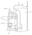
도 4a는 본 발명의 일 실시예에 따른 도어의 정면을 도시한 도면이며, 도 4b는 본 발명의 일 실시예에 따른 도어 커버의 후면을 도시한 도면이다.FIG. 4A is a front view of a door according to an embodiment of the present invention, and FIG. 4B is a rear view of a door cover according to an embodiment of the present invention.
도 4a 및 도 4b에 도시된 바와 같이, 도어 커버(110)는 중심에 개구(110a)가 마련되며, 제1부분(111)과 제2부분(112)을 포함한다. 제1부분(111)은 도어 커버(110)로 입사되는 빛이 통과되도록 구성된다. 제2부분(112)은 적어도 일부분이 제1부분(111)에 투영되도록 구성된다. 따라서, 외측에서 제1부분(111)을 통해 제2부분(112)의 적어도 일부분을 볼 수 있다. 제1부분(111)과 제2부분(112)은 도어 커버(110)의 테두리부를 따라 형성된다. 제1부분(111)이 외측에 위치하며, 제2부분(112)은 제1부분(111)의 내측에 위치할 수 있다. 즉, 제1부분(111)과 제2부분(112)은 동심원의 형태로 마련될 수 있다. As shown in FIGS. 4A and 4B, the
도어(100)의 일측에는 사용자가 도어(100)를 개폐하기 위해 파지 가능한 손잡이(114)가 마련될 수 있다. 본 발명의 일 실시예에 따르면, 손잡이부(114)는 도어 커버(110)의 내측 테두리부의 적어도 일부분이 함몰되도록 마련될 수 있다. 제1부분(111)은 손잡이부(114)가 위치하는 내측 테두리부를 감싸도록 마련될 수 있다. 제1부분(111)의 내측에 제2부분(112)이 위치하여 손잡이부(114)의 색, 재질을 표현할 수 있다. A
본 발명의 일 실시예에 따르면, 제1부분(111)은 투명한 소재로 형성되며, 제2부분(112)은 불투명한 소재로 마련될 수 있다. 특히, 제2부분(112)은 유색의 불투명한 소재로 형성될 수 있다. 일 예로, 제1부분(111)은 폴리메틸메타크릴레이트(PMMA; polymethyl metacrylate), 폴리카보네이트(PC; Polycrbonate)과 같은 플라스틱 중 적어도 어느 하나로 이루어질 수 있다. 제2부분(112)은 아크릴로나이트릴-부타다이엔-스타이렌 수지(ABS;acrylonitrile butadiene styrene copolymer)로 마련될 수 있다. According to an embodiment of the present invention, the
제1부분(111)과 제2부분(112)은 일체로 이중 사출 성형될 수 있다. 본 발명의 일 실시예에 따르면, 제1부분(111)이 1차로 사출 성형된 후 제2부분(112)을 2차로 사출 성형하나, 이와 반대로 제2부분(112)을 1차로 사출 성형한 후, 제1부분(111)을 2차로 사출 성형 하는 것도 가능하다. The
도어 커버(110)의 후면에는 사출물이 투입된 사출공(113)이 형성된다. 도면에 도시된 본 발명의 일 실시예에 따르면, 4개의 사출공(113)이 마련될 수 있다. 이 4개의 사출공(113)은 2차 사출 성형 후의 사출공이며, 1차 사출 성형 후의 사출공을 포함하면 총 8개의 사출공이 마련될 수 있다.An injection hole 113 into which an injection material is injected is formed on the rear surface of the
도어 커버(110)의 후면에는 도어 커버(110)와 글라스 홀더(120)를 결합시키기 위한 구성 요소들이 위치할 수 있다. 이에 대해서는 후술한다. Components for coupling the
도 5는 본 발명의 일 실시예에 따른 도어를 분해하여 도시한 분해도이다. 5 is an exploded view illustrating a door according to an embodiment of the present invention.
도 5에 도시된 바와 같이, 도어(100)는 최외측에 위치하는 도어 커버(110)와, 세탁기 내측으로 돌출되는 글라스(130)와, 도어 커버(110)와 결합되어 글라스(130)를 지지하는 글라스 홀더(120)를 포함한다. 5, the
본 발명의 일 실시예에 따르면, 도어(100)는 원형으로 마련되나, 이에 제한 되는 것은 아니다. 도어 커버(110)는 도어(100)의 전면을 형성하며, 도어 커버(110)의 후면에는 글라스 홀더(120)와의 결합을 위한 구조가 위치한다. According to an embodiment of the present invention, the
이에 대응하여 글라스 홀더(120)의 전면에는 도어 커버(110)와의 결합을 위한 구조가 위치한다. 글라스 홀더(120)는 도어(100)가 폐쇄되었을 때, 캐비닛(10)의 오목부에 접할 수 있다. 또한, 글라스(130)와의 결합을 위한 글라스 안착부(126)가 마련될 수 있다. 글라스(130)에는 글라스 홀더(120)에 글라스(130)를 결합시키기 위한 글라스 리브(132)가 마련될 수 있다. Correspondingly, a structure for engagement with the
글라스 홀더(120)는 도어 커버(110)와 글라스(130) 사이에 배치되며, 도어 커버(110)와의 결합을 위하여 적어도 하나 이상의 후크홈(123)을 포함할 수 있다. 또한, 예비적으로, 체결부재(미도시)의 결합을 위한 결합홀(125)이 추가적으로 마련될 수 있다. 이에 따라 글라스 홀더(120)와 도어 커버(110)는 후크에 의한 결합이 가능하며, 체결부재(미도시)를 이용해 결합되는 것도 가능하다. 또한, 강성 보강을 위한 리브구조(127)가 마련될 수 있다. The
글라스 홀더(120)의 일측에는 도어(100)가 회동 가능하도록 설치되도록 힌지 유닛(150)이 결합되는 결합부(121)가 마련될 수 있다. 또한, 글라스 홀더(120)의 다른 일측에는 도어(100)가 투입구를 닫을 때 도어(100)를 잠그기 위한 래치(160)가 결합될 수 있다. The
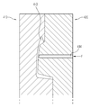
도 6은 본 발명의 일 실시예에 따른 도어 커버의 단면을 도시한 단면도이며,도 7은 본 발명의 일 실시예에 따른 도어 커버와 홀더 글라스의 결합 단면을 도시한 단면도이다. FIG. 6 is a cross-sectional view of a door cover according to an embodiment of the present invention, and FIG. 7 is a cross-sectional view illustrating a coupling section of a door cover and a holder glass according to an embodiment of the present invention.
도 6 및 도 7에 도시된 바와 같이, 도어 커버(110)와 글라스 홀더(120)는 서로 맞물려 결합한다. 도어 커버(110)는 일체로 형성된다. 도어 커버(110)의 외측면에는 투명한 소재의 제1부분(111)이 위치하며, 제1부분(111)의 내측에는 불투명한 소재의 제2부분(112)이 위치한다. 도면에 도시된 바에 따르면, 도어 커버(110)의 결합돌기(115)는 글라스 홀더(120)의 결합홀(125)에 삽입되어 도어 커버(110)와 5글라스 홀더(120)가 결합되나, 이에 제한되는 것은 아니며 후크 구조에 의한 결합도 가능하다. 이에 대해서는 후술한다. As shown in Figs. 6 and 7, the
제1부분(111)은 제2부분(112)과 결합하는 제1영역(111a)과, 제2부분(112)과 결합되지 않은 제2영역(111b)을 포함할 수 있다. 제1부분(111)이 투명한 소재로 마련되기 때문에 제2부분(112)과 결합되지 않은 제2영역(111b)은 투명하게 마련될 수 있다. 또한, 제1영역(111a)의 경우 제2부분(112)과 결합하기 때문에 제2부분(112)이 투영되기 때문에 소비자는 외측에서 제2부분(112)이 투영된 제1부분(111)을 볼 수 있다. 제1영역과 제2영역은 동심원의 형태로 마련되며, 제1영역이 동심원의 중심에 위치할 수 있다. 제2영역(111b)의 경우 제2부분(112)과 결합되지 않으며, 외측에서 입사되는 빛이 제2영역(111b)에서 산란되기 때문에 외측에서 봤을 때 메탈 색상을 띨 수 있다. The
제1부분(111)은 소정의 각도로 경사지게 형성된 경사부(140)를 포함할 수 있다. 경사부(140)는 제1부분(111)의 테두리부(141)에 형성된다. 테두리부(141)가 도어 커버(110)의 수직면에 대해 기울어진 각도를 α라 정의한다. 본 발명의 일 실시예에 따르면, α는 40°내지 50°미만의 각도로 마련될 수 있다. 그러나 이에 제한되는 것은 아니며 α는 0° 초과 90°미만의 각도로 마련될 수 있다. The
경사부(140)는 도어 커버(110)와 글라스 홀더(120)의 결합면(142)에도 마련된다. 결합면(142)이 도어 커버(110)의 수직면에 대해 기울어진 각도를 β라 정의한다. 본 발명의 일 실시예에 따르면, β는 40°내지 50°미만의 각도로 마련될 수 있다. 그러나 이에 제한되는 것은 아니며 β는 0° 초과 90°미만의 각도로 마련될 수 있다. The
본 발명의 일 실시예에 따르면, α와 β는 비대칭적으로 마련될 수 있다. 경사부(140)와 결합되는 글라스 홀더(120)의 최대 두께(d1)는 1cm 미만으로 마련될 수 있다. According to an embodiment of the present invention,? And? May be provided asymmetrically. The maximum thickness d1 of the
본 발명의 일 실시예에 따르면, 제1부분(111)은 투명한 소재로 마련되며, 제1영역(111)의 테두리부(141)에 경사부(140)가 마련되기 때문에 빛이 투과하면서 굴절률의 차이가 생기게 된다. 따라서, 제1영역(11)과 제2영역(112)의 경계가 굴절률의 차이로 인해 메탈색을 띤게된다. 즉, 도어 커버(110)와 글라스 홀더(120)의 결합면(142)이 메탈색을 띤다.According to an embodiment of the present invention, the
본 발명의 일 실시예에 따르면 소비자가 세탁기(1)를 외측에서 보았을 때, 캐비닛(10)과 도어(100)의 경계가 메탈색을 띠게 된다. 따라서, 도어(100)에 별도의 장식적 구성이 없는 경우에도 도어(100)와 캐비닛(10)을 구별할 수 있다. 또한, 본 발명의 일 실시예와 같이 손잡이(114)가 도어(100)의 외측면이 아닌 내측면에 위치하는 경우, 도어(100)와 캐비닛(10)의 구별이 필수적이기 때문에 간단한 공정으로 도어(100)와 캐비닛(10)을 구별시킬 수 있다. 또한, 결합면(242)은 도어 커버(210) 또는 글라스 홀더(220)와 다른 색상을 띠나, 이를 위하여 이종의 플라스틱을 사용하고 있지 않을 뿐만 아니라 도어 커버(210) 사출 성형 후 후가공을 필요로 하지 않는다. 따라서, 간단한 제조 공정으로 디자인적 효과를 누릴 수 있을 뿐 아니라 제조비의 절감이 가능하다. According to an embodiment of the present invention, when the consumer views the washing machine 1 from the outside, the boundary between the
도 8은 본 발명의 다른 실시예에 따른 도어 커버와 글라스 홀더의 결합 단면을 도시한 단면도이다. FIG. 8 is a cross-sectional view illustrating an engagement section between a door cover and a glass holder according to another embodiment of the present invention.
도 8에 도시된 본 발명의 일 실시예에 따르면, 도어 커버(210)에 제1부분(211), 제2부분(212)이 마련되며, 도어 커버(210)와 글라스 홀더(220)가 결합홈(225)을 통해 결합된다는 점은 도 7에 도시된 실시예와 동일하다.8, the
다만, 도 8의 경우에는 도어 커버(210)에 도 7에 도시된 바와 같은 경사부가 마련되지 않는다는 점에서 차이가 있다. However, in the case of FIG. 8, there is a difference in that the
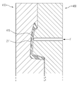
도 9는 본 발명의 또 다른 실시예에 따른 도어 커버와 글라스 홀더의 결합 단면을 도시한 단면도이다. FIG. 9 is a cross-sectional view illustrating an engagement section between a door cover and a glass holder according to another embodiment of the present invention.
도 9에 도시된 본 발명의 일 실시예에 따르면, 제1부분(311) 또는 제2부분(312) 중 적어도 하나에 요철부(350)가 형성될 수 있다. 요철부(350)는 표면이 돌출된 돌출부(351)와 표면이 파인 오목부(352)가 교대로 형성되어 마련된다. According to an embodiment of the present invention shown in FIG. 9, at least one of the
본 발명의 일 실시예에 따르면, 요철부(350)는 제1부분(311)의 내측면에 마련된다. 즉, 제1부분(311)과 제2부분(312)의 경계부에 마련될 수 있다. 그러나, 이에 제한되는 것은 아니다. 본 발명의 일 실시예에 따르면, 요철부(350)가 투명한 소재의 제1부분(311)의 내측에 마련되기 때문에, 도어 커버(310)로 투영된 빛은 요철부(350)의 돌출부(351)와 오목부(352)로 인해 급격하게 색조가 변화된다. 따라서, 요철부(350)의 돌출부(351)와 오목부(352)가 이루는 형상이 도어 커버(310)에 두드러지게 표현된다. 요철부(350)의 형상은 다양하게 마련될 수 있으며, 이에 따라 도어 커버(310)에 다양한 형상을 나타낼 수 있다. 또한, 불투명한 소재로 마련되는 제2부분(312)이 다양한 색상을 가지는 경우에는 요철부(350)와 함께 새로운 디자인적 미감을 창출하는 것이 가능하다. According to one embodiment of the present invention, the concave-
도 10은 본 발명의 또 다른 실시예에 따른 도어 커버와 홀더 글라스의 결합 단면을 도시한 도면이다. 10 is a cross-sectional view illustrating a door cover and a holder glass according to another embodiment of the present invention.
본 발명의 일 실시예에 따르면, 제1부분(511)과 제2부분(512)의 적어도 일부분이 서로 이격되도록 마련되는 갭(543)이 마련될 수 있다. 갭(543)은 제1부분(511)의 테두리부(541)과 제2부분(512)의 결합면(542)의 사이에 마련될 수 있다. According to an embodiment of the present invention, a
갭(543)을 통해 도어 커버(110)의 외측에서 들어오는 빛이 산란되기 때문에 제1부분(511)과 제2부분(512)의 경계가 메탈색을 띨 수 있다. 본 발명의 일 실시예에 따르면, 갭(543)은 1mm내외로 마련될 수 있으나, 이에 제한되는 것은 아니다. The boundary between the
도 11은 본 발명의 또 다른 실시예에 따른 도어를 분해하여 도시한 분해도이다. 11 is an exploded view illustrating a door according to another embodiment of the present invention.
도 11에 도시된 바와 같이, 도어(100)는 상술한 대로 도어커버(610)와, 글라스(130)와, 글라스 홀더(120)를 포함한다. 동일한 도면부호의 경우 상술한 바와 동일한 내용을 포함하므로 설명을 생략한다.11, the
본 발명의 일 실시예에 따르면, 도어 커버(610)의 제1부분(611)과 제2부분(612)이 각각 별도의 부재로 마련될 수 있다. 이에 따라, 제1부분(611)과 제2부분(612)이 결합되어 도어커버(610)를 구성할 수 있다. 제1부분(611)과 제2부분(612)의 결합은 다양한 방식으로 이루어질 수 있으며, 일 예로 체결부재를 이용한 체결과 초음파 융착을 이용하는 것이 가능하다. According to an embodiment of the present invention, the
도 12a 내지 도 12c는 본 발명의 다른 실시예에 따른 도어 커버가 사출 성형되는 과정을 간략히 도시한 도면이다. 12A to 12C are schematic views illustrating a process of injection molding a door cover according to another embodiment of the present invention.
도 12a 내지 도 12c는 제1부분을 1차 사출하고, 제2부분을 2차 사출하는 과정을 도시한 도면으로, 이하 사출 과정을 설명한다.12A to 12C are diagrams illustrating a process of first injection of a first portion and second injection of a second portion, and the injection process will be described below.
도 12a에 도시한 바와 같이, 제1부분인 1차 사출부(413)의 형상을 사출하기 위해 베이스 금형(410)에 제1사출 금형(420)이 접근하여 밀착된다. 베이스 금형(410)과 제1사출 금형(420)이 서로 접근한 부위에는 제1부분 형상의 공간인 1차 사출부(413)가 마련된다. 제1사출 금형(420)에는 1차 사출부(413)에 1차 주입 방향(F)로 1차 사출물을 주입하기 위한 1차 사출공(414)이 마련된다. 제1영역은 1차 사출공(414)으로 1차 사출물을 주입하여 1차 사출부(413)를 채우는 방식으로 형성된다. As shown in FIG. 12A, the
도 12b는 제1부분에 대한 1차 사출이 끝난 후 실링 금형인 제2사출 금형(430)이 결합되는 과정을 도시하였다. 1차 사출이 끝나면 제1사출 금형(420)은 제거되고, 제2사출 금형(430)이 베이스 금형(410) 방향으로 접근한다. 1차 사출이 끝났으므로 1차 사출물인 제1부분(211)은 베이스 금형(410) 상에 사출되어 있다. FIG. 12B illustrates a process in which the
도 12c는 실링 금형인 제2사출 금형(430)이 결합된 상태를 도시하였다. 베이스 금형(410)과 제2사출 금형(430)이 서로 접근한 부위에는 제2부분 형상의 공간인 2차 사출부(415)가 마련된다. 제2사출 금형(430)에는 2차 사출부(415)에 2차 주입 방향(F)로 2차 사출물을 주입하기 위한 2차 사출공(416)이 마련된다. 제2부분은 2차 사출공(416)으로 2차 사출물을 주입하여 2차 사출부(415)를 채우는 방식으로 형성된다. 12C shows a state in which the
2차 사출공(416)으로 2차 사출물이 주입되고 사출물의 흔적은 도어 커버(210)의 후면에서 볼 수 있다. 도 4B에 도시된 본 발명의 일 실시예에 따르면, 4개의 2차 사출공(113)이 위치하는 것을 볼 수 있다. Secondary injection holes are injected into the secondary injection holes 416, and traces of the injection holes can be seen from the rear surface of the
1차 사출과 2차 사출을 거쳐 생성된 도어 커버는 도어 커버의 표면에 온도 차이로 인해 크랙이 생성되는 것을 방지하기 위해 냉각 과정을 거칠 수 있다. The door cover produced through the primary injection and the secondary injection may be cooled to prevent cracks from being generated due to the temperature difference on the surface of the door cover.
도 13는 본 발명의 일 실시예에 따른 노브를 분해하여 도시한 도면이다.13 is an exploded view of a knob according to an embodiment of the present invention.
도 13에 도시된 바와 같이, 노브(80)는 노브 커버(81)와, 노브 커버(81)의 내측에 위치하는 노브 홀더(82)와, 노브 홀더(82)의 내측에 위치하는 노브 본체(85)를 포함한다. 13, the
노브 커버(81)는 본 발명의 일 실시예에 따른 도어 커버와 같이 재질이 다른 제1부분(83)과 제2부분(84)을 포함한다. 제1부분(83)은 투명한 소재로 이루어질 수 있으며, 제2부분(84)은 불투명한 소재로 마련될 수 있다. 일 예로, 제1영역(83)은 폴리메틸메타크릴레이트(PMMA; polymethyl metacrylate), 폴리카보네이트(PC; Polycrbonate)과 같은 플라스틱 중 적어도 어느 하나로 이루어질 수 있다. 제2영역(84)은 아크릴로나이트릴-부타다이엔-스타이렌 수지(ABS;acrylonitrile butadiene styrene copolymer)로 마련될 수 있다. 제1부분(83)과 제2부분(84)은 상기 기술한 바와 같은 사출 방법에 의해 일체로 형성될 수 있다. The
도 14는 본 발명의 또 다른 실시예에 따른 홀더 글라스를 도시한 도면이며, 도 15은 본 발명의 또 다른 실시예에 따른 도어 커버를 도시한 도면이며, 도 16는 본 발명의 또 다른 실시예에 따른 홀더 글라스와 도어 커버가 결합된 상태의 단면을 도시한 도면이다. FIG. 14 is a view showing a holder glass according to another embodiment of the present invention, FIG. 15 is a view showing a door cover according to another embodiment of the present invention, and FIG. 16 is a view showing another embodiment In which the holder glass and the door cover are coupled to each other.
도 14 내지 도 16에 도시된 바와 같이, 홀더 글라스(520)와 도어 커버(510)는 후크 결합될 수 있다. As shown in Figs. 14-16, the
홀더 글라스(520)에는 도어 커버(510)와의 결합을 위해 적어도 하나 이상의 후크 결합홈(524)을 포함할 수 있다. 도면에 도시된 후크 결합홈(524) 중 외측에 위치하는 후크 결합홈(524)에 도어 커버(510)의 후크(517)가 결합될 수 있다. 후크 결합홈(524)은 홀더 글라스(520)의 내벽(523)의 일부분에 마련될 수 있다. The
또한, 홀더 글라스(520)에는 스크류와 같은 체결부재가 체결될 수 있는 적어도 하나 이상의 결합홀(525)이 위치할 수 있으나, 이는 예비로 만들어진 것일 뿐 필수적인 부분은 아니다. In addition, the
또한, 홀더 글라스(520)의 바닥면의 적어도 일부분에는 결합재가 채워질 수 있도록 유로(527)가 마련될 수 있다. 결합재로는 우레탄이 사용될 수 있다. 이는 홀더 글라스(520)와 도어 커버(510) 사이의 간극을 채워서 결합력을 향상시키기 위함이다. Further, at least a part of the bottom surface of the
도어 커버(510)의 후면에는 후크 결합홈(524)에 결합되는 적어도 하나 이상의 후크(517)가 위치할 수 있다. At least one
도어 커버(510)의 후면에는 홀더 글라스(520)와의 결합을 위해 적어도 하나 이상의 후크(517)가 마련될 수 있다. 후크(517)는 도어 커버(510)의 내벽(511)에 마련될 수 있다. 또한, 결합홀(525)에 삽입되는 적어도 하나 이상의 결합돌기(515)가 마련될 수 있다. At least one
도어 커버(510)와 홀더 글라스(520)의 결합은 도어 커버(510)의 후크(517)가 홀더 글라스(520)의 후크 결합홈(524)에 결합되어 이루어질 수 있다. 후크 결합홈(524)의 폭은 후크(517)의 적어도 일부의 폭보다 작게 형성될 수 있다. 따라서 후크(517)가 후크 결합홈(524)에 삽입되는 경우, 후크(517)와 후크 결합홈(524)이 마련된 홀더 글라스(520)의 내벽(523) 사이에 간섭이 작용하게 되기 때문에 후크(517)와 후크 결합홈(524)의 결합력을 높일 수 있다. The coupling of the
도어 커버(510)와 홀더 글라스(520)가 후크(517)와 후크 결합홈(524)을 통해 결합되는 경우에는 스크류와 같은 체결부재를 이용한 결합이 필요하지 않다. 따라서, 도어 커버(510)의 결합돌기(515)와 홀더 글라스(520)의 결합홀(525)은 후크(517) 또는 후크 결합홈(524)이 파손되는 경우를 대비하여 마련된다. When the
종래에는 결합홀(525)과 결합돌기(515)에 스크류와 같은 체결부재(미도시)가 결합되었으며, 결합력을 높이기 위해 총 10개의 체결부재(미도시)를 필요로 하였다. 그러나 본 발명의 일 실시예에 따르면 이러한 체결부재(미도시)를 필요로 하지 않으며, 체결부재(미도시)를 추가하는 공정이 필요 없기 때문에 원가 절감과 공정의 간소화가 가능하다. Conventionally, a coupling member (not shown) such as a screw is coupled to the
이상에서는 특정의 실시예에 대하여 도시하고 설명하였다. 그러나, 상기한 실시예에만 한정되지 않으며, 발명이 속하는 기술분야에서 통상의 지식을 가진 자라면 이하의 청구범위에 기재된 발명의 기술적 사상의 요지를 벗어남이 없이 얼마든지 다양하게 변경 실시할 수 있을 것이다. The foregoing has shown and described specific embodiments. However, it should be understood that the present invention is not limited to the above-described embodiment, and various changes and modifications may be made without departing from the technical idea of the present invention described in the following claims .
1: 세탁기 10: 캐비닛
20: 외조 30: 내조
100: 도어 110, 210, 310: 도어 커버
111, 211, 311: 제1부분 112, 212, 312: 제2부분
240, 340: 경사부 120, 220, 320: 글라스 홀더
130: 글라스 350: 요철부1: Washing machine 10: Cabinet
20: outer tub 30: inner tub
100:
111, 211, 311:
240, 340:
130: glass 350: concave and convex portion
Claims (25)
상기 캐비닛 내측에 위치하며 세탁수를 수용 가능한 터브;
상기 터브의 내측에 위치하며 세탁물을 수용 가능한 드럼;
상기 투입구를 개폐하는 도어;를 포함하며,
상기 도어는,
중심에 마련되는 개구와, 외측에 위치하며 빛이 통과되도록 투명한 소재로 마련되는 제1부분과, 상기 제1부분과 동심원 형태로 마련되도록 상기 제1부분의 내측에 위치하며 상기 제1부분을 통해 투영되도록 불투명한 소재로 상기 제1부분과 일체로 성형되는 제2부분을 포함하는 도어 커버를 포함하며,
상기 제1부분은,
상기 제2부분이 투영될 수 있도록 상기 제2부분과 결합된 제1영역과, 상기 제2부분과 결합되지 않은 제2영역을 포함하며,
상기 제2영역은 상기 제1영역보다 상기 개구의 중심에서 멀리 위치하는 것을 특징으로 하는 세탁기. A cabinet forming an appearance and having an inlet;
A tub located inside the cabinet and capable of receiving wash water;
A drum disposed inside the tub and capable of receiving laundry;
And a door for opening and closing the inlet,
The door
A first portion disposed at an outer side of the first portion and made of a transparent material through which light is allowed to pass; a second portion positioned inside the first portion so as to be concentric with the first portion, And a door cover including a second portion integrally molded with the first portion in an opaque material so as to be projected,
Wherein the first portion comprises:
A first region coupled with the second portion such that the second portion can be projected, and a second region not coupled with the second portion,
And the second region is located farther from the center of the opening than the first region.
상기 제1영역은 소정의 각도로 경사지게 형성된 경사부를 포함하는 것을 특징으로 하는 세탁기. The method according to claim 1,
Wherein the first region includes an inclined portion formed to be inclined at a predetermined angle.
상기 제1부분과 상기 제2부분 중 적어도 하나에는 표면이 돌출된 돌출부와, 표면이 파인 오목부가 교대로 형성되는 요철부가 형성되는 것을 특징으로 하는 세탁기. The method according to claim 1,
Wherein at least one of the first portion and the second portion is provided with a protruding portion whose surface protrudes and a concavo-convex portion in which a concave portion with a fine surface is alternately formed.
상기 제1부분과 상기 제2부분의 사이에서 빛의 산란이 일어나도록 상기 제1부분과 상기 제2부분의 적어도 일부분이 이격되도록 갭이 마련되는 것을 특징으로 하는 세탁기. The method according to claim 1,
Wherein a gap is provided such that at least a part of the first part and the second part are spaced apart so that scattering of light occurs between the first part and the second part.
상기 도어 커버의 후면에 결합되는 글라스 홀더를 더 포함하는 것을 특징으로 하는 세탁기. The method according to claim 1,
And a glass holder coupled to a rear surface of the door cover.
상기 도어 커버와 상기 글라스 홀더의 사이에 결합되는 글라스를 더 포함하는 것을 특징으로 하는 세탁기. 8. The method of claim 7,
And a glass coupled between the door cover and the glass holder.
상기 제1부분은 폴리메틸메타크릴레이트(PMMA; polymethyl metacrylate), 폴리카보네이트(PC; Polycrbonate) 중 적어도 어느 하나로 이루어진 것을 특징으로 하는 세탁기. The method according to claim 1,
Wherein the first portion is made of at least one of polymethyl methacrylate (PMMA) and polycarbonate (PC).
상기 제2부분은 아크릴로나이트릴-부타다이엔-스타이렌 수지(ABS;acrylonitrile butadiene styrene copolymer)로 이루어진 것을 특징으로 하는 세탁기.The method according to claim 1,
And the second portion is made of acrylonitrile butadiene styrene copolymer (ABS).
상기 캐비닛 내측에 위치하며 세탁수를 수용 가능한 터브;
상기 터브의 내측에 위치하며 세탁물을 수용 가능한 드럼;
상기 투입구를 개폐하는 도어;를 포함하며,
상기 도어는,
상기 도어 커버의 적어도 일부분에 투명한 소재로 마련되는 제1부분과, 적어도 일부분에 불투명한 소재로 마련되는 제2부분을 포함하며,
상기 제1부분은 상기 제2부분과 결합되는 제1영역과, 상기 제2부분과 결합되지 않은 제2영역을 포함하며,
상기 제2영역은 빛의 산란으로 인해 메탈 색상을 띠는 것을 특징으로 하는 세탁기. A cabinet forming an appearance and having an inlet;
A tub located inside the cabinet and capable of receiving wash water;
A drum disposed inside the tub and capable of receiving laundry;
And a door for opening and closing the inlet,
The door
A first portion provided on at least a part of the door cover with a transparent material and a second portion provided with at least a part opaque material,
Wherein the first portion includes a first region coupled with the second portion and a second region not coupled with the second portion,
Wherein the second region is formed of a metal color due to scattering of light.
상기 제1부분과 상기 제2부분은 상기 도어 커버의 테두리를 따라 형성되며, 상기 제1부분이 외측에 위치하며, 상기 제1부분의 내측에 상기 제2부분이 위치하는 것을 특징으로 하는 세탁기. 10. The method of claim 9,
Wherein the first portion and the second portion are formed along the rim of the door cover, the first portion is located on the outer side, and the second portion is located on the inner side of the first portion.
상기 제1부분과 상기 제2부분 사이에는 빛의 산란을 위한 갭이 형성되는 것을 특징으로 하는 세탁기.10. The method of claim 9,
And a gap for light scattering is formed between the first portion and the second portion.
상기 제1부분은 상기 세탁기의 내측 방향으로 40ㅀ 내지 50ㅀ경사지게 형성된 경사부를 포함하는 것을 특징으로 하는 세탁기. 10. The method of claim 9,
Wherein the first portion includes an inclined portion inclined at an angle of 40 to 50 degrees with respect to an inward direction of the washer.
상기 제1부분은 내면이 돌출된 돌출부와 내면이 상기 도어 커버의 외측 방향으로 파인 오목부를 포함하는 요철부를 더 포함하는 것을 특징으로 하는 세탁기. 10. The method of claim 9,
Wherein the first portion further includes a protruded portion having an inner surface protruding and a recessed portion having an inner surface including a recessed portion that is recessed in the outer direction of the door cover.
상기 캐비닛 내측에 위치하며 세탁수를 수용 가능한 터브
상기 터브의 내측에 위치하며 세탁물을 수용 가능한 드럼;
상기 투입구를 개폐하는 도어;를 포함하며,
상기 도어는.
적어도 일부분에 마련되는 제1부분과, 상기 제1부분과 일체로 사출성형되는 제2부분을 포함하며,
상기 제1부분과 제2부분 중 적어도 하나의 일측에 위치하며, 빛의 투과율 차이를 발생시켜 상기 캐비닛과 상기 도어 커버의 외관상 차이가 시각적으로 인식될 수 있도록 마련되는 경사부;
를 포함하는 것을 특징으로 하는 세탁기. A cabinet forming an appearance and having an inlet;
And a tub disposed inside the cabinet and capable of receiving wash water,
A drum disposed inside the tub and capable of receiving laundry;
And a door for opening and closing the inlet,
The door comprises:
A first portion provided at least in part and a second portion injection molded integrally with the first portion,
An inclined portion which is located at one side of at least one of the first portion and the second portion and is provided so as to visually recognize a difference in appearance between the cabinet and the door cover by generating a light transmittance difference;
Wherein the washing machine comprises a washing machine.
상기 제1부분의 내측에 상기 제2부분이 위치하는 것을 특징으로 하는 세탁기. 15. The method of claim 14,
And the second portion is located inside the first portion.
상기 경사부는 상기 세탁기의 내측 방향으로 경사지게 마련되는 것을 특징으로 하는 세탁기. 15. The method of claim 14,
Wherein the inclined portion is inclined inwardly of the washing machine.
상기 도어와 접촉하는 상기 캐비닛의 적어도 일부분은 내측으로 함몰된 오목부를 더 포함하며, 상기 오목부는 상기 글라스 홀더와 접촉하는 것을 특징으로 하는 세탁기.15. The method of claim 14,
At least a portion of the cabinet contacting the door further includes an inwardly recessed portion, the recess being in contact with the glass holder.
입사되는 빛이 통과되도록 구성되는 제1부분을 1차 사출 성형하고,
상기 제1부분의 내측에 위치하며 상기 제1부분을 통해 적어도 일부분이 투영되는 제2부분을 2차 사출 성형하는 것을 포함하는 것을 특징으로 하는 세탁기의 도어의 제조방법. A method of manufacturing a door for opening and closing an inlet of a washing machine,
A first part configured to pass incident light is first injection molded,
And performing a secondary injection molding of a second portion located inside the first portion and at least part of which is projected through the first portion.
상기 제1부분은 투명한 소재로 이루어지며, 상기 제2부분은 유색의 불투명한 소재로 이루어지는 것을 특징으로 하는 세탁기 도어의 제조방법. 19. The method of claim 18,
Wherein the first portion is made of a transparent material and the second portion is made of a color opaque material.
상기 제1부분의 1차 사출 성형 후, 소정 시간동안 냉각되는 과정을 더 포함하는 것을 특징으로 하는 세탁기의 도어의 제조방법.19. The method of claim 18,
Further comprising the step of cooling the first part after the first injection molding for a predetermined period of time.
상기 제2부분의 2차 사출 성형 후, 소정 시간동안 냉각되는 과정을 더 포함하는 것을 특징으로 하는 세탁기의 도어의 제조방법. 21. The method of claim 20,
Further comprising the step of cooling the second part after the second injection molding for a predetermined time.
상기 제1부분은 소정 각도로 경사지게 형성된 경사부를 포함하는 것을 특징으로 하는 세탁기의 도어의 제조방법. 19. The method of claim 18,
Wherein the first portion includes an inclined portion that is inclined at a predetermined angle.
상기 제1부분과 상기 제2부분은 상기 도어의 외측에 결합되는 도어 커버에 마련되는 것을 특징으로 하는 세탁기의 도어의 제조방법.19. The method of claim 18,
Wherein the first portion and the second portion are provided on a door cover coupled to the outside of the door.
상기 도어 커버의 사출 성형 후, 글라스가 결합되는 과정을 더 포함하는 것을 특징으로 하는 세탁기의 도어의 제조방법. 24. The method of claim 23,
Further comprising the step of joining the glass after the injection molding of the door cover.
상기 글라스의 결합 후에, 상기 글라스를 고정시키기 위한 글라스 홀더가 결합되는 과정을 더 포함하는 것을 특징으로 하는 세탁기의 도어의 제조방법. 24. The method of claim 23,
Further comprising the step of assembling a glass holder for fixing the glass after the glass is coupled.
Priority Applications (8)
| Application Number | Priority Date | Filing Date | Title |
|---|---|---|---|
| PCT/KR2014/000118 WO2014109518A1 (en) | 2013-01-09 | 2014-01-07 | Washing machine and method of manufacturing door thereof |
| MX2015008870A MX2015008870A (en) | 2013-01-09 | 2014-01-07 | Washing machine and method of manufacturing door thereof. |
| CA2897595A CA2897595C (en) | 2013-01-09 | 2014-01-07 | Washing machine and method of manufacturing door thereof |
| US14/149,281 US10590590B2 (en) | 2013-01-09 | 2014-01-07 | Washing machine and method of manufacturing door thereof |
| AU2014205881A AU2014205881B2 (en) | 2013-01-09 | 2014-01-07 | Washing machine and method of manufacturing door thereof |
| RU2015127625A RU2615263C2 (en) | 2013-01-09 | 2014-01-07 | Washing machine and method for producing its doors |
| EP14150653.5A EP2754746B1 (en) | 2013-01-09 | 2014-01-09 | Washing machine and method of manufacturing door thereof |
| CN201410010806.9A CN103911798B (en) | 2013-01-09 | 2014-01-09 | The method of the door of washing machine and manufacture washing machine |
Applications Claiming Priority (2)
| Application Number | Priority Date | Filing Date | Title |
|---|---|---|---|
| KR1020130002658 | 2013-01-09 | ||
| KR20130002658 | 2013-01-09 |
Publications (2)
| Publication Number | Publication Date |
|---|---|
| KR20140090541A true KR20140090541A (en) | 2014-07-17 |
| KR102137946B1 KR102137946B1 (en) | 2020-07-27 |
Family
ID=51738146
Family Applications (1)
| Application Number | Title | Priority Date | Filing Date |
|---|---|---|---|
| KR1020130091715A KR102137946B1 (en) | 2013-01-09 | 2013-08-01 | Washing Machine and Manufacturing Method of Door |
Country Status (5)
| Country | Link |
|---|---|
| KR (1) | KR102137946B1 (en) |
| AU (1) | AU2014205881B2 (en) |
| CA (1) | CA2897595C (en) |
| MX (1) | MX2015008870A (en) |
| RU (1) | RU2615263C2 (en) |
Cited By (1)
| Publication number | Priority date | Publication date | Assignee | Title |
|---|---|---|---|---|
| WO2023239014A1 (en) * | 2022-06-09 | 2023-12-14 | 삼성전자주식회사 | Clothing treatment apparatus |
Citations (6)
| Publication number | Priority date | Publication date | Assignee | Title |
|---|---|---|---|---|
| KR100483664B1 (en) * | 2003-12-30 | 2005-04-19 | 엘지전자 주식회사 | Drum washer's door |
| KR20050114348A (en) * | 2004-06-01 | 2005-12-06 | 엘지전자 주식회사 | A door assembling structure and assembling method of a cylinder typed washer |
| KR20060007262A (en) * | 2004-07-19 | 2006-01-24 | 엘지전자 주식회사 | A door structure of a cylinder typed washer |
| EP1762650A2 (en) * | 2005-09-13 | 2007-03-14 | Miele & Cie. KG | Porthole door for a front load washing machine |
| US7694537B2 (en) * | 2003-12-30 | 2010-04-13 | Lg Electronics Inc. | Door for drum type washing machine and method of manufacturing door with decorative part |
| CN102648315A (en) * | 2009-12-07 | 2012-08-22 | Bsh博世和西门子家用电器有限公司 | Door for a household appliance having a viewing window and method for production of said door |
Family Cites Families (4)
| Publication number | Priority date | Publication date | Assignee | Title |
|---|---|---|---|---|
| KR100595180B1 (en) * | 2002-07-31 | 2006-07-03 | 엘지전자 주식회사 | door of clothes dryer/drum-type washing machine |
| AU2004229041B2 (en) * | 2003-12-30 | 2011-01-20 | Lg Electronics Inc. | Door of drum-type washing machine, method of manufacturing door with hairline sheet of drum-type washing machine, and method of manufacturing hairline sheet for door |
| KR101542376B1 (en) * | 2008-08-08 | 2015-08-06 | 엘지전자 주식회사 | Door for washing machine |
| EP2243874B1 (en) * | 2009-04-22 | 2012-07-04 | Electrolux Home Products Corporation N.V. | Porthole door for laundry washing machines and household appliance provided with said porthole door |
-
2013
- 2013-08-01 KR KR1020130091715A patent/KR102137946B1/en active IP Right Grant
-
2014
- 2014-01-07 CA CA2897595A patent/CA2897595C/en active Active
- 2014-01-07 AU AU2014205881A patent/AU2014205881B2/en not_active Ceased
- 2014-01-07 RU RU2015127625A patent/RU2615263C2/en active
- 2014-01-07 MX MX2015008870A patent/MX2015008870A/en unknown
Patent Citations (6)
| Publication number | Priority date | Publication date | Assignee | Title |
|---|---|---|---|---|
| KR100483664B1 (en) * | 2003-12-30 | 2005-04-19 | 엘지전자 주식회사 | Drum washer's door |
| US7694537B2 (en) * | 2003-12-30 | 2010-04-13 | Lg Electronics Inc. | Door for drum type washing machine and method of manufacturing door with decorative part |
| KR20050114348A (en) * | 2004-06-01 | 2005-12-06 | 엘지전자 주식회사 | A door assembling structure and assembling method of a cylinder typed washer |
| KR20060007262A (en) * | 2004-07-19 | 2006-01-24 | 엘지전자 주식회사 | A door structure of a cylinder typed washer |
| EP1762650A2 (en) * | 2005-09-13 | 2007-03-14 | Miele & Cie. KG | Porthole door for a front load washing machine |
| CN102648315A (en) * | 2009-12-07 | 2012-08-22 | Bsh博世和西门子家用电器有限公司 | Door for a household appliance having a viewing window and method for production of said door |
Cited By (1)
| Publication number | Priority date | Publication date | Assignee | Title |
|---|---|---|---|---|
| WO2023239014A1 (en) * | 2022-06-09 | 2023-12-14 | 삼성전자주식회사 | Clothing treatment apparatus |
Also Published As
| Publication number | Publication date |
|---|---|
| AU2014205881A1 (en) | 2015-07-02 |
| AU2014205881B2 (en) | 2016-03-31 |
| CA2897595C (en) | 2017-06-27 |
| CA2897595A1 (en) | 2014-07-17 |
| RU2615263C2 (en) | 2017-04-04 |
| RU2015127625A (en) | 2017-01-16 |
| KR102137946B1 (en) | 2020-07-27 |
| MX2015008870A (en) | 2015-10-30 |
Similar Documents
| Publication | Publication Date | Title |
|---|---|---|
| US10590590B2 (en) | Washing machine and method of manufacturing door thereof | |
| KR102160965B1 (en) | Washing Machine and Manufacturing Method of Door | |
| JP4636148B2 (en) | Drum washing machine | |
| US7716957B2 (en) | Drum type washing machine with door ring | |
| JP5091113B2 (en) | Cleaning device and manufacturing method and assembly method of cleaning device | |
| US20050262681A1 (en) | Door of drum washer and assembling method for the same | |
| KR20160029389A (en) | Washing machine | |
| JP2009213804A (en) | Drum type washing machine | |
| AU2014314517A1 (en) | Door assembly for a laundry treatment device | |
| KR102137946B1 (en) | Washing Machine and Manufacturing Method of Door | |
| AU2014314511B2 (en) | Door assembly for a laundry treatment device | |
| US9739006B2 (en) | Washing machine and manufacturing method of door | |
| JP2013052010A (en) | Drum type washing machine | |
| JP6949154B2 (en) | Clothes processing equipment | |
| AU2014314512A1 (en) | A door assembly for a laundry treatment device and method of operation | |
| KR20210115326A (en) | Laundry treating apparatus | |
| KR100737315B1 (en) | Washing machine | |
| JP2023056829A (en) | Clothing treatment device | |
| KR100465147B1 (en) | Drum washer's door and manufacturing method of drum washer's door with hairline | |
| JP2020074984A (en) | Vertical type washing machine | |
| KR20130123542A (en) | Door for drum type washing machine |
Legal Events
| Date | Code | Title | Description |
|---|---|---|---|
| E902 | Notification of reason for refusal | ||
| AMND | Amendment | ||
| E601 | Decision to refuse application | ||
| AMND | Amendment | ||
| X701 | Decision to grant (after re-examination) | ||
| GRNT | Written decision to grant |