KR20140079470A - Optical trocar system - Google Patents
Optical trocar system Download PDFInfo
- Publication number
- KR20140079470A KR20140079470A KR1020147012900A KR20147012900A KR20140079470A KR 20140079470 A KR20140079470 A KR 20140079470A KR 1020147012900 A KR1020147012900 A KR 1020147012900A KR 20147012900 A KR20147012900 A KR 20147012900A KR 20140079470 A KR20140079470 A KR 20140079470A
- Authority
- KR
- South Korea
- Prior art keywords
- optical member
- diameter
- optical
- elongate
- endoscope
- Prior art date
Links
Images


Classifications
-
- A—HUMAN NECESSITIES
- A61—MEDICAL OR VETERINARY SCIENCE; HYGIENE
- A61B—DIAGNOSIS; SURGERY; IDENTIFICATION
- A61B1/00—Instruments for performing medical examinations of the interior of cavities or tubes of the body by visual or photographical inspection, e.g. endoscopes; Illuminating arrangements therefor
- A61B1/00147—Holding or positioning arrangements
- A61B1/00154—Holding or positioning arrangements using guiding arrangements for insertion
-
- A—HUMAN NECESSITIES
- A61—MEDICAL OR VETERINARY SCIENCE; HYGIENE
- A61B—DIAGNOSIS; SURGERY; IDENTIFICATION
- A61B1/00—Instruments for performing medical examinations of the interior of cavities or tubes of the body by visual or photographical inspection, e.g. endoscopes; Illuminating arrangements therefor
- A61B1/00064—Constructional details of the endoscope body
- A61B1/00071—Insertion part of the endoscope body
- A61B1/0008—Insertion part of the endoscope body characterised by distal tip features
- A61B1/00096—Optical elements
-
- A—HUMAN NECESSITIES
- A61—MEDICAL OR VETERINARY SCIENCE; HYGIENE
- A61B—DIAGNOSIS; SURGERY; IDENTIFICATION
- A61B1/00—Instruments for performing medical examinations of the interior of cavities or tubes of the body by visual or photographical inspection, e.g. endoscopes; Illuminating arrangements therefor
- A61B1/00131—Accessories for endoscopes
-
- A—HUMAN NECESSITIES
- A61—MEDICAL OR VETERINARY SCIENCE; HYGIENE
- A61B—DIAGNOSIS; SURGERY; IDENTIFICATION
- A61B1/00—Instruments for performing medical examinations of the interior of cavities or tubes of the body by visual or photographical inspection, e.g. endoscopes; Illuminating arrangements therefor
- A61B1/313—Instruments for performing medical examinations of the interior of cavities or tubes of the body by visual or photographical inspection, e.g. endoscopes; Illuminating arrangements therefor for introducing through surgical openings, e.g. laparoscopes
- A61B1/3132—Instruments for performing medical examinations of the interior of cavities or tubes of the body by visual or photographical inspection, e.g. endoscopes; Illuminating arrangements therefor for introducing through surgical openings, e.g. laparoscopes for laparoscopy
-
- A—HUMAN NECESSITIES
- A61—MEDICAL OR VETERINARY SCIENCE; HYGIENE
- A61B—DIAGNOSIS; SURGERY; IDENTIFICATION
- A61B1/00—Instruments for performing medical examinations of the interior of cavities or tubes of the body by visual or photographical inspection, e.g. endoscopes; Illuminating arrangements therefor
- A61B1/313—Instruments for performing medical examinations of the interior of cavities or tubes of the body by visual or photographical inspection, e.g. endoscopes; Illuminating arrangements therefor for introducing through surgical openings, e.g. laparoscopes
- A61B1/3137—Instruments for performing medical examinations of the interior of cavities or tubes of the body by visual or photographical inspection, e.g. endoscopes; Illuminating arrangements therefor for introducing through surgical openings, e.g. laparoscopes for examination of the interior of blood vessels
-
- A—HUMAN NECESSITIES
- A61—MEDICAL OR VETERINARY SCIENCE; HYGIENE
- A61B—DIAGNOSIS; SURGERY; IDENTIFICATION
- A61B17/00—Surgical instruments, devices or methods, e.g. tourniquets
- A61B17/34—Trocars; Puncturing needles
-
- A—HUMAN NECESSITIES
- A61—MEDICAL OR VETERINARY SCIENCE; HYGIENE
- A61B—DIAGNOSIS; SURGERY; IDENTIFICATION
- A61B17/00—Surgical instruments, devices or methods, e.g. tourniquets
- A61B17/34—Trocars; Puncturing needles
- A61B17/3417—Details of tips or shafts, e.g. grooves, expandable, bendable; Multiple coaxial sliding cannulas, e.g. for dilating
- A61B17/3421—Cannulas
-
- A—HUMAN NECESSITIES
- A61—MEDICAL OR VETERINARY SCIENCE; HYGIENE
- A61B—DIAGNOSIS; SURGERY; IDENTIFICATION
- A61B17/00—Surgical instruments, devices or methods, e.g. tourniquets
- A61B17/34—Trocars; Puncturing needles
- A61B17/3478—Endoscopic needles, e.g. for infusion
-
- A—HUMAN NECESSITIES
- A61—MEDICAL OR VETERINARY SCIENCE; HYGIENE
- A61B—DIAGNOSIS; SURGERY; IDENTIFICATION
- A61B90/00—Instruments, implements or accessories specially adapted for surgery or diagnosis and not covered by any of the groups A61B1/00 - A61B50/00, e.g. for luxation treatment or for protecting wound edges
- A61B90/36—Image-producing devices or illumination devices not otherwise provided for
- A61B90/37—Surgical systems with images on a monitor during operation
-
- A—HUMAN NECESSITIES
- A61—MEDICAL OR VETERINARY SCIENCE; HYGIENE
- A61B—DIAGNOSIS; SURGERY; IDENTIFICATION
- A61B17/00—Surgical instruments, devices or methods, e.g. tourniquets
- A61B2017/00526—Methods of manufacturing
-
- A—HUMAN NECESSITIES
- A61—MEDICAL OR VETERINARY SCIENCE; HYGIENE
- A61B—DIAGNOSIS; SURGERY; IDENTIFICATION
- A61B17/00—Surgical instruments, devices or methods, e.g. tourniquets
- A61B2017/00831—Material properties
- A61B2017/00902—Material properties transparent or translucent
- A61B2017/00907—Material properties transparent or translucent for light
-
- A—HUMAN NECESSITIES
- A61—MEDICAL OR VETERINARY SCIENCE; HYGIENE
- A61B—DIAGNOSIS; SURGERY; IDENTIFICATION
- A61B17/00—Surgical instruments, devices or methods, e.g. tourniquets
- A61B17/34—Trocars; Puncturing needles
- A61B17/3417—Details of tips or shafts, e.g. grooves, expandable, bendable; Multiple coaxial sliding cannulas, e.g. for dilating
- A61B2017/3454—Details of tips
- A61B2017/3456—Details of tips blunt
-
- A—HUMAN NECESSITIES
- A61—MEDICAL OR VETERINARY SCIENCE; HYGIENE
- A61B—DIAGNOSIS; SURGERY; IDENTIFICATION
- A61B17/00—Surgical instruments, devices or methods, e.g. tourniquets
- A61B17/34—Trocars; Puncturing needles
- A61B17/3417—Details of tips or shafts, e.g. grooves, expandable, bendable; Multiple coaxial sliding cannulas, e.g. for dilating
- A61B2017/3454—Details of tips
- A61B2017/346—Details of tips with wings
-
- A—HUMAN NECESSITIES
- A61—MEDICAL OR VETERINARY SCIENCE; HYGIENE
- A61B—DIAGNOSIS; SURGERY; IDENTIFICATION
- A61B17/00—Surgical instruments, devices or methods, e.g. tourniquets
- A61B17/34—Trocars; Puncturing needles
- A61B2017/347—Locking means, e.g. for locking instrument in cannula
Abstract
제1 직경을 갖는 세장형 폐색구 부재를 포함하는 광학 투관침 시스템. 세장형 폐색구 부재는 원위 영역을 가지며, 상기 원위 영역은 세장형 폐색구 부재의 제1 직경과 실질적으로 동일한 직경을 갖는 제1 직경부를 갖는다. 세장형 폐색구 부재는 제1 직경보다 작은 직경을 갖는 제2 직경부를 갖는다. 광학 투관침 시스템은 또한 광학부재가 세장형 폐색구 부재의 제2 직경부 및 제1 직경부의 적어도 일부분을 봉쇄하도록 세장형 폐색구 부재의 원위 영역에 부착된 광학부재를 포함한다. 세장형 튜브 폐색구 부재를 통과하는 길이방향 보어는 내시경을 수용하도록 구성되어 있다. An optical trocar system comprising a elongate occlusion member having a first diameter. The elongated occlusion member has a distal region and the distal region has a first diameter that is substantially the same as the first diameter of the elongated occlusion member. The elongate occlusion member has a second diameter portion having a diameter smaller than the first diameter. The optical trocar system also includes an optical member attached to a distal region of the elongate occlusion member such that the optical member seals at least a portion of the second diameter and the first diameter of the elongate occlusion member. The longitudinal bore passing through the elongate tube closure member is configured to receive the endoscope.

Description
본 출원은 참조로 그 전체 내용을 여기에 포함하고 있는, 2011년 10월 18일자 출원된, 미국 가출원 제61/548,428호의 이득 및 우선권을 청구한다. This application claims benefit and priority of U.S. Provisional Application No. 61 / 548,428, filed October 18, 2011, the entire contents of which are incorporated herein by reference.
본 개시는 신체 조직을 해부하기 위한 투관침(trocar) 시스템에 관한 것이다. 특히, 본 개시는 칼날없는(bladeless) 광학 투관침 시스템에 관한 것이다. This disclosure relates to trocar systems for dissecting body tissues. In particular, this disclosure relates to a bladeless optical trocar system.
내시경 및 복강경 최소 침습 수술은 의료기구를 환자 내부로 주입하여 환자 몸의 여러 부분을 보는데 사용되고 있다. 통상적으로, 필요한 해부 부위를 보기 위해, 외과의사는 내시경을 환자 안으로 삽입하여 해부 부위의 영상을 만든다. 내시경 수술 과정에서, 피부에 상처를 낸 작은 입구를 통해 삽입된 좁은 내시경 튜브(캐뉼라)를 통해 신체의 어떠한 중공 기관 또는 조직에서 수술이 실행된다. 복강경 수술에서, 복부 내의 외과수술 작업은 작은 절개부(보통 약 0.5 내지 약 1.5 cm)를 통해 시행된다. Endoscopic and laparoscopic minimally invasive surgery is used to infuse a medical device into a patient and to view various parts of the patient's body. Typically, to see the required dissection site, the surgeon inserts an endoscope into the patient to create an image of the anatomical site. During endoscopic surgery, surgery is performed on any hollow organs or tissues of the body through a narrow endoscopic tube (cannula) inserted through a small opening wounded on the skin. In laparoscopic surgery, surgical operation within the abdomen is performed through a small incision (usually about 0.5 to about 1.5 cm).
본 발명은 종래 기술을 개선한 광학 투관침 시스템을 제공하는 것이다.SUMMARY OF THE INVENTION The present invention provides an optical trocar system that improves upon the prior art.
실시예에 따라서, 본 발명은 광학 투관침 시스템에 관한 것으로서, 광학 투관침 시스템은, 제1 직경을 갖는 세장형 폐색구 부재로서. 상기 세장형 폐색구 부재는 원위 영역을 가지며, 상기 원위 영역은 상기 세장형 폐색구 부재의 제1 직경과 실질적으로 동일한 직경을 갖는 제1 직경부와 상기 제1 직경보다 작은 직경을 갖는 제2 직경부를 갖는 상기 세장형 폐색구 부재; 및 광학부재가 상기 세장형 폐색구 부재의 제2 직경부 및 제1 직경부의 적어도 일부분을 봉쇄하도록 상기 세장형 폐색구 부재의 원위 영역에 부착된 광학부재를 포함한다. 광학 투관침 시스템은 또한 캐뉼러 조립체를 포함할 수 있다. 세장형 튜브 부재는 캐뉼라 조립체 내에 삽입되기 위한 구조로 될 수 있다. According to an embodiment, the present invention relates to an optical trocar system, wherein the optical trocar system is a elongate obturator member having a first diameter. The elongated occlusion member having a distal region, the distal region having a first diameter having a diameter substantially equal to the first diameter of the elongated occlusion member and a second diameter having a diameter less than the first diameter, The elongated obstruction member having a portion; And an optical member attached to a distal region of the elongate occlusion member such that the optical member seals at least a portion of the second diameter and the first diameter of the elongate occlusion member. The optical trocar system may also include a cannula assembly. The elongate tubular member may be configured for insertion into the cannula assembly.
유리하게, 광학부재는 튜브 부재의 최원위(distalmost) 단부로부터 원위측으로 연장한다. 세장형 튜브 부재는 길이방향 보어를 형성할 수 있다. 길이방향 보어는 내시경을 수용하도록 구성될 수 있다. 세장형 튜브 부재는 근위 영역에서 하우징을 포함하고, 상기 하우징은 개구부와, 상기 개구부에 인접하여 내시경을 수용하며 내시경을 유지하기 위한 범위 유지 부재를 포함한다. 광학부재는 내시경으로 조직의 시각화를 허용하기 위해 적어도 부분적으로 투명할 수 있다. 광학부재는 길이방향 축에 대하여 경사지게 배열된 내부 경사면을 형성할 수 있다. 상기 내부 경사면은 내시경의 원위 단부의 최외측 주변과 결합하도록 구성되며 치수가 정해질 수 있다. 내부 경사면은 내시경의 원위 단부와 광학부재 사이에 공기 갭을 제공할 수 있다. Advantageously, the optical member extends distally from the distalmost end of the tube member. The elongate tubular member may form a longitudinal bore. The longitudinal bore may be configured to receive the endoscope. The elongate tubular member includes a housing in a proximal region, the housing including an opening and a region retaining member for receiving the endoscope adjacent the opening and for retaining the endoscope. The optical member may be at least partially transparent to allow visualization of the tissue with the endoscope. The optical member may form an inner inclined surface arranged obliquely with respect to the longitudinal axis. The inner inclined surface is configured and dimensioned to engage an outermost periphery of the distal end of the endoscope. The inner inclined surface may provide an air gap between the distal end of the endoscope and the optical member.
광학부재는 조직을 절단(cutting) 또는 절개(incising)함이 없이 조직면들(tissue planes) 사이를 해부(dissect)하도록 구성될 수 있다. 광학부재는 최원위 단부에서 둥근 안내 너브(rounded guiding nub)를 형성할 수 있다. 광학부재의 외부면의 중심부는 직경방향으로 대향한 한 쌍의 대체로 볼록한 표면을 포함할 수 있다. 광학부재의 외부면의 중심부는 또한 상기 직경방향으로 대향한 한 쌍의 대체로 볼록한 표면들 사이에서 원주방향으로 위치한 직경방향으로 대향한 한 쌍의 오목한 표면들을 포함할 수 있다. 광학부재는, 상기 광학부재의 외부면이 세장형 튜브 폐색구 부재의 외경과 실질적으로 동일한 직경을 갖도록 튜브 부재의 원위 영역에 몰딩될 수 있다. 광학부재는 중공을 가질 수 있다. The optical member may be configured to dissect between tissue planes without cutting or incising the tissue. The optical member may form a rounded guiding nub at the uppermost end. The central portion of the outer surface of the optical member may include a pair of generally convex surfaces diametrically opposed. The central portion of the outer surface of the optical member may also include a pair of diametrically opposed, concave surfaces located circumferentially between the pair of diametrically opposed, generally convex surfaces. The optical member may be molded in the distal region of the tube member such that the outer surface of the optical member has a diameter substantially the same as the outer diameter of the elongate tube occluding member. The optical member may have a hollow.
다양한 실시예에서, 제2 직경부는 적어도 하나의 보이드(void)를 포함할 수 있으며, 광학부재는 상기 적어도 하나의 보이드의 적어도 일부분을 봉쇄할 수 있다. 광학부재는 상기 세장형 폐색구 부재에 몰딩됨으로써, 예로서 오버몰딩됨으로써 상기 세장형 폐색구 부재의 원위 영역에 부착될 수 있다. 실시예에 따라, 본 발명은 원위 단부에서 광학부재를 갖는 세장형 폐색구 부재를 포함하는 광학 투관침 시스템에 관한 것으로서, 상기 광학부재의 외부면의 중심부는 직경방향으로 대향한 한 쌍의 대체로 볼록한 표면들을 포함하고, 그리고 상기 광학부재의 외부면의 중심부는 상기 직경방향으로 대향한 한 쌍의 대체로 볼록한 표면들 사이에서 원주방향으로 위치하는 직경방향으로 대향한 한 쌍의 오목한 표면들을 포함한다. 광학부재는 조직을 절단 또는 절개함이 없이 조직면들 사이를 해부하도록 구성될 수 있다. 광학부재는 최원위 단부에서 둥근 안내 너브를 형성할 수 있다. 세장형 튜브 부재는 근위 영역에서 하우징을 포함하고, 상기 하우징은 개구부와, 상기 개구부에 인접하여 내시경을 수용하며 내시경을 유지하기 위한 범위 유지 부재를 포함한다. In various embodiments, the second diameter may comprise at least one void, and the optical member may contain at least a portion of the at least one void. The optical member may be attached to the distal region of the elongate occlusion member by being molded into the elongated occlusion member, for example by overmolding. According to an embodiment, the present invention relates to an optical trocar system comprising a elongate obturator member having an optical element at a distal end, wherein a central portion of the outer surface of the optical member comprises a pair of generally convex surfaces And a central portion of the outer surface of the optical member includes a pair of diametrically opposed, concave surfaces positioned circumferentially between the pair of diametrically opposed generally convex surfaces. The optical member may be configured to dissect between tissue surfaces without cutting or incising the tissue. The optical member may form a rounded guide nub at the uppermost end. The elongate tubular member includes a housing in a proximal region, the housing including an opening and a region retaining member for receiving the endoscope adjacent the opening and for retaining the endoscope.
본 개시의 상기 양상 및 기타 양상들과, 특징 및 장점들은 첨부 도면과 연관된 아래의 상세한 설명에 비추어 더 명확하게 될 것이다.
도 1은 광학 액세스 장치 및 캐뉼라 조립체를 예시하는 본 개시의 실시예에 따른 광학 투관침(예로서 가시적 폐색구(visual obturator)) 시스템의 분배 사시도.
도 2는 도 1의 실시예에 따른 광학 투관침 시스템의 완전 조립된 사시도.
도 3은 도 1 및 도 2의 실시예에 따른 광학 투관침 시스템의 광학부재의 확대 사시도.
도 4는 도 1의 광학부재의 평면도.
도 5는 도 3의 광학부재의 축방향 도면.
도 6은 도 4의 평면도에 대하여 반경방향으로 90°오프셋된 광학부재의 측면도.
도 6a는 대략 광학부재의 길이방향 중간점에서 취한 도 6의 광학부재의 전방 단면도.
도 6b는 세장형 튜브 부재의 원위 단부 영역과 도 2의 광학 투관침 시스템의 광학부재의 단면도.
도 6c는 내시경을 내부에 배치한 상태에서 도 6b의 광학 액세스 장치의 광학부재 및 세장형 튜브 부재의 원위 단부 영역의 단면도.
도 7은 도 1의 완전 조립된 광학 투관침 시스템의 후면 사시도.
도 8은 도 1의 광학 액세스 장치에서 폐색구 하우징의 범위 유지 부재의 사시도.
도 9는 도 2의 캐뉼라 조립체의 커버의 평면도.
도 10은 캐뉼라 조립체의 커버의 단면도.
도 11은 도 1의 캐뉼라 조립체의 커버의 사시도.
도 12는 도 1의 캐뉼라 조립체의 기구 밀봉부의 사시도.
도 13은 도 1의 캐뉼라 조립체의 기구 밀봉부의 단면도.
도 14는 광학 액세스 장치 내에 위치하여 인체 조직에 접근하는 내시경을 도시하는 사시도. These and other aspects, features, and advantages of the present disclosure will become more apparent in light of the following detailed description taken in conjunction with the accompanying drawings.
BRIEF DESCRIPTION OF THE DRAWINGS Figure 1 is a distributed perspective view of an optical trocar (e.g., a visual obturator) system in accordance with an embodiment of the present disclosure illustrating an optical access device and a cannula assembly.
Figure 2 is a fully assembled perspective view of an optical trocar system according to the embodiment of Figure 1;
Figure 3 is an enlarged perspective view of an optical member of an optical trocar system according to the embodiment of Figures 1 and 2;
4 is a plan view of the optical member of Fig.
5 is an axial view of the optical member of Fig. 3;
Figure 6 is a side view of an optical member offset 90 [deg.] In the radial direction with respect to the plan view of Figure 4;
6A is a front sectional view of the optical member of Fig. 6 taken at the longitudinal midpoint of the optical member;
Figure 6b is a cross-sectional view of the distal end region of the elongate tubular member and the optical member of the optical trocar system of Figure 2;
6C is a cross-sectional view of the distal end region of the optical member and elongate tube member of the optical access device of Fig. 6B with the endoscope positioned therein. Fig.
Figure 7 is a rear perspective view of the fully assembled optical trocar system of Figure 1;
Fig. 8 is a perspective view of a range holding member of the occlusion housing in the optical access device of Fig. 1; Fig.
Figure 9 is a plan view of the cover of the cannula assembly of Figure 2;
10 is a cross-sectional view of a cover of a cannula assembly;
Figure 11 is a perspective view of the cover of the cannula assembly of Figure 1;
Figure 12 is a perspective view of the instrument seal of the cannula assembly of Figure 1;
Figure 13 is a cross-sectional view of the instrument seal of the cannula assembly of Figure 1;
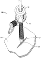
14 is a perspective view showing an endoscope positioned within the optical access device and approaching the body tissue;
본 개시의 특별한 실시예는 첨부 도면을 참고하여 이하에 설명되어 있지만, 개시된 실시예는 단순히 개시의 실례에 불과하고 다양한 형태로 구체화될 수 있음을 이해할 것이다. 공지된 기능 또는 구조는 불필요한 세부사항으로 본 개시를 모호하게 하는 것을 회피하기 위해 상세히 설명되지 않는다. 따라서, 여기에 개시된 특정한 구조 및 기능적 세부는 제한하는 것으로 해석되어서는 안되며, 단지 청구범위를 위한 기초로서 그리고 실제로 어떤 적절하게 상세한 구조로서 본 개시를 다양하게 사용하도록 통상의 기술자에게 가르치기 위한 대표적인 기초로서 해석되어야 한다. 도면의 설명에 걸쳐 유사 도면부호는 유사 요소 또는 동일 요소를 지칭한다.Although specific embodiments of the present disclosure are described below with reference to the accompanying drawings, it will be appreciated that the disclosed embodiments are merely illustrative of the disclosure and may be embodied in various forms. Well-known functions or constructions are not described in detail so as not to obscure the present disclosure with unnecessary detail. Accordingly, the specific structure and functional details disclosed herein should not be construed as limiting, but merely as a basis for teaching one of ordinary skill in the art various uses of the disclosure as a basis for the claims and indeed any appropriately detailed structure Should be interpreted. Like numbers refer to like elements or like elements throughout the description of the drawings.
본원에 사용된 바와 같이, 용어 "원위(distal)"는 사용자로부터 더 멀리 떨어져 있는 기구의 그 부분 또는 기구의 구성요소를 지칭하며, 한편 용어 "근위(proximal)"는 사용자에게 더 가까이 있는 기구의 그 부분 또는 기구의 구성요소를 지칭한다. As used herein, the term " distal "refers to that part of a device or apparatus that is further away from the user, while the term" proximal " Quot; refers < / RTI >
본 발명은 다양한 실시예에 따라서, 해부학상(예로서 복부) 벽을 통해 신체 내강에 접근하는 광학 투관침 시스템에 관한 것이다. 주목해야 할 것은, 이러한 설명을 위해서, 용어 광학 투관침 시스템(optical trocar system)은 본원에서 종종 용어 가시적 폐색구 시스템과 동의어로 사용되고 있다는 것이다. 유리하게는, 본 발명의 광학 투관침 시스템은, 다양한 실시예에 따라서, 조직을 절단 또는 절개함이 없이, 오히려 외과 수술 중에 조직면들을 분리함으로써 그러한 접근을 제공한다. 또한 본 발명의 광학 투관침 시스템은, 다양한 실시예에 따라서, 폐색구의 원위 단부에 투명 광학부재를 배치함으로써 신체 조직 섬유들이 분리되어 있을 때 신체 조직 섬유들의 시각화를 제공하며 따라서 신체 벽을 가로질러 제어된 순회(traversal)을 허용할 수 있다. The present invention relates to an optical trocar system for accessing the body lumen via anatomical (e.g., abdominal) walls, according to various embodiments. It should be noted that for the purposes of this description, the term optical trocar system is often used herein synonymously with the term visual occlusion system. Advantageously, the optical trocar system of the present invention provides such an approach, without cutting or incising the tissue, but rather by separating the tissue surfaces during surgery, according to various embodiments. The optical trocar system of the present invention also provides for the visualization of body tissue fibers when the body tissue fibers are separated by placing a transparent optical member at the distal end of the occlusion ball, according to various embodiments, It may allow traversal.
이제 도 1 내지 도 14를 참고하면, 본 발명의 실시예에 따라 광학 투관침(예로서 가시적 폐색구) 시스템이 도시되어 있다. 가시적 폐색구는 내시경(예로서 복강경) 외과수술에서 조직면들을 분리하도록 만들어져 있으며, 특히 외과수술 중에 복부 내벽(lining)의 블런트 해부(blunt dissection)에 적절하다. 가시적 폐색구는, 수술 부위를 향하여 가시적 폐색구를 삽입하여 전진하는 동안 조직을 보기 위해 내시경을 수용하도록 구성되어 있다. Referring now to Figures 1 to 14, an optical trocar (e.g., a visual occlusion) system is shown in accordance with an embodiment of the present invention. Visible occlusion is designed to separate tissue surfaces during endoscopic (eg, laparoscopic) surgery and is particularly suitable for blunt dissection of the abdominal wall lining during surgery. Visible obstruction is configured to accommodate the endoscope to view the tissue while advancing by inserting a visible obstruction toward the surgical site.
도시된 실시예에 따라서, 가시적 폐색구 시스템(10)은 폐색구 조립체(11), 및 상기 폐색구 조립체(11)를 적어도 부분적으로 수용하는 캐뉼라 조립체(100)를 포함한다. 폐색구 조립체(11)는 세장형 폐색구 부재(14)와 기계적으로 상호작용하도록 배치되며 길이방향 축 "A-A"를 규정하는 폐색구 하우징(12)을 포함한다. 세장형 폐색구 부재(14)는 폐색구 하우징(12)으로부터 원위측으로 연장한다. According to the illustrated embodiment, the
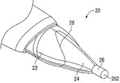
세장형 폐색구 부재(14)는 강성(예로서 금속) 폐색구 샤프트(18)를 포함하며, 상기 폐색구 샤프트는 그 근위 단부가 폐색구 하우징(12)에 예로서 오버몰딩에 의하여 부착되고 그 원위 단부가 광학부재(20)에 부착되어 있다. 도 3 내지 도 6에 도시된 바와 같이, 광학부재(20)는 근위부(22), 중심부(24), 및 비외상성(atraumatic) 안내 너브(26)를 포함한다. 광학부재(20)는 중공 내부를 갖는다. 도 6c에 도시된 바와 같이, 내시경의 원위 관찰(viewing) 팁은 광학부재(20) 내에서 경사/모따기(chamfer) 표면과 결합하게 되며, 이는 이하에서 설명될 것이다. 도 3 내지 도 6을 참고하면, 가상선(28)(곡률을 예시하도록 도시됨)은 근위부(22)와 중심부(24) 사이에서 경계를 표현할 수 있다. The
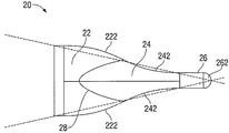
도 4를 참고하면, 광학부재(20)의 평면도가 도시되어 있다. 도시된 바와 같이, 근위부(22)는 한 쌍의 직경방향으로 대향한 볼록면(222)을 포함한다. 중심부(24)는 한 쌍의 직경방향으로 대향한 오목면들(242)을 포함한다. 비외상성 안내 너브(26)는 중심부(24)에서부터 원위측으로 연장하며 대체로 원통형이고, 둥근 단부(262)를 포함한다. 둥근 단부(262)는 조직에 외상을 일으키지 않도록 하는 치수로 된 곡률 반경을 형성한다. 추가로, 원추를 나타내는 팬텀 라인(phantom line)(29)과 연결지어 도시된 바와 같이, 광학부재(20)의 근위부(22) 및 비외상성 안내 너브(26) 양쪽의 일부분은 원추의 차원을 벗어나 있다. 4, a plan view of the
도 5를 참고하면, 광학부재(20)의 단부 또는 축방향 도면은 안내 너브(26)의 원형 프로파일, 중심부(241)의 타원 프로파일, 및 근위부(22)의 원형 프로파일을 도시한다. 5, an end or axial view of the
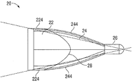
도 6을 참고하면, 광학부재(20)의 측면도가 도시되어 있다. 이 측면도는 도 4의 평면도에 대하여 반경방향으로 90°오프셋되어 있다. 도시된 바와 같이, 광학부재(20)의 근위부(22)는 추가로, 대체로 직선 및/또는 볼록한 한 쌍의 직경방향으로 대향한 외부면(224)을 포함한다. 중심부(24)는 또한 볼록한 한 쌍의 대향한 외부면(244)을 포함한다. 따라서, 광학부재(20)의 중심부(24)는, 광학부재(20)에 대하여 원주방향으로 이격되어 있는, 대체로 오목한 표면(242)(도 4) 및 대체로 볼록한 표면(244)(도 6) 모두를 포함하고 있다. 이러한 방법으로, 광학부재(20)는 "돌핀-노즈(dolpin-nose)" 또는 "낙하산" 타입 형상을 가질 수 있다. 덧붙여, 원추를 나타내는 도 6에서 팬텀 라인과 연결지어 도시된 바와 같이, 광학부재(20)의 근위부(22), 중심부(24) 및 비외상성 안내 너브(26)의 일부분은 원추의 차원에서 벗어나 있다. Referring to Fig. 6, a side view of the
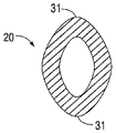
도 6a는 대략 길이방향 중간점에서 취한 광학부재(20)의 전방 단면도이다. 도면은 사용 중에 조직면들을 따라 조직을 분리하는데 도움을 주는 작용을 하는 둥근 외부면(31)을 포함하는 것을 도시하고 있다. 6A is a front cross-sectional view of the
비외상성 안내 너브(26)는 조직에서 사전형성된 개구부(예로서, 사전절개된 메스 절개부) 내에 초기 삽입을 허용하고, 조직의 어떠한 절단 또는 절개 없이, 조직을 부드럽게 해부하기 위해 조직층들 사이로 광학부재(20)의 전진을 용이하게 한다. 초기 삽입 및 계속적인 원위 삽입 후에, 중심부(24) 및 근위부(22)는 조직면들을 더욱 해부함으로써, 예를 들어 광학부재의 클록(clocking) 운동 중에 광학부재의 둥근 외부면(31)이 조직면들을 분리함으로써 조직의 개구부를 부드럽게 계속해서 확장한다. The
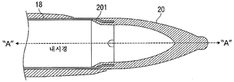
도 6b 및 도 6c를 참고하면, 광학부재(20)는 폴리머 재료, 예로서 LEXAN으로 제조될 수 있고, 그리고 광선의 통과를 허용하기 위해 투명하거나 또는 적어도 반투명하다. 조립 중에, 광학부재(20)는 구성요소들을 연결하기 위해 금속 폐색구 샤프트(18)에 오버몰딩될 수 있다. 특히, 폐색구 샤프트(18)는 길이방향 축(A-A)에 대하여 반경방향 내향으로 매달려 있는 원위 샤프트 섹션을 포함한다. 광학부재(20)는 원위 샤프트 섹션을 봉쇄하도록 몰딩되고, 폴리머 재료의 경화시에 폐색구 샤프트(18)에 고정된다. 광학부재(20)는 길이방향 축(A-A)에 대하여 경사지게 배열되어 있는 내부 모따기면 또는 경사면(201)을 형성한다. 모따기면(201)은, 내시경의 영역으로부터 외부 주변 내에 반경방향으로 전달된 빛이 모따기면 또는 경사면(201)에서 받아들이기 전에 공기 갭을 가로질러 이동하도록 내시경의 원위 단부의 최외측 주변(도 6c)과 직접 결합된다. 광학부재(20)는, 조직을 통해 가시적 폐색구 시스템(10)의 삽입 및/또는 전진 중에 광학부재(20)에 인접한 조직을 (내시경에 의하여) 볼 수 있도록 광선의 통과를 허용한다. 6B and 6C, the
폐색구 조립체(11)의 폐색구 하우징(12)은 개구부(160)(도 7) 및 상기 개구부(160)에 인접한 범위 유지 부재(170)(도 8에 별개로 도시됨)를 포함한다. 범위 유지 부재(170)는 엘라스토머 재료로 제조되며, 그리고 내시경을 수용하기 위한 중심 개구부(172)와 상기 중심 개구부(172)로부터 외향으로 연장하는 4개의 반경방향 슬릿(174)을 형성한다. 반경방향 슬릿(174)은 내시경의 삽입 시에 범위 유지 부재(170)의 굴곡과 중심 개구부(172)의 확장을 허용한다. 범위 유지 부재(170)는 폐색구 조립체(11) 내에서 내시경의 상대적 위치설정을 유지하는 것을 도와주기 위하여 내시경의 외부면과 마찰 결합으로 결합하도록 구성되어 있다. The
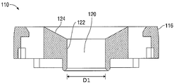
다시 도 1을 참고하면, 가시적 폐색구 시스템(10)의 캐뉼라 조립체(100)는 길이방향 축 "B-B"을 규정하는 투명한 세장형 부분(102), 및 커버(110)를 포함할 수 있다. 커버(110)는 기구 밀봉부(130) 및 제로-폐쇄(zero-closure) 밀봉부(150)를 둘러싸고 있다. 기구 밀봉부(130)는 제로-폐쇄 밀봉부(150)의 근위측에 배치되어 있다. Referring again to FIG. 1, the
커버(110)는 세장형 부분(102)의 근위 부분과 기계적으로 결합하도록 구성되어 있으며, 캐뉼라 하우징 내에 기구 밀봉부(130) 및 제로-폐쇄 밀봉부(150)를 유지하는 것으로 도와준다. 도 9를 참고하면, 커버(110)는 외부 주변(116)과, 직경 D1을 갖는 구멍(aperture)(120)을 포함한다. 램프부(ramped section)(124)는 외부 주변(116)을 구멍(120)과 상호연결한다. 추가로, 구멍(120)은 수직의 내부 측벽(122)들(도 10) 사이에 형성되어 있다. 또한 커버(110)는 한 쌍의 노치(126)와 한 쌍의 결합부(127)를 포함한다. 노치(126)들 및 결합부(127)들은 폐색구 부재(14)(도 1)에 배치된 한 쌍의 돌기부(23) 및 한 쌍의 래치(19)와 제각기 기계적으로 결합하도록 구성되어 있다. 도 1을 참고하면, 래치(19)들 상의 버튼(27)들은 폐색구 하우징(12) 내에서 개구부(21)들을 통해 연장하여, 사용자가 (예로서 래치(19)들의 근위 단부들이 커버(110)의 결합부(127)들과 결합하도록 버튼(27)을 누름으로써) 선택적으로 폐색구를 캐뉼라 조립체(100)에 로크(lock)하거나 언로크(unlock)할 수 있다. The
이제 도 12 및 도 13을 참고하면, 기구 밀봉부(130)는 강성 플라스틱 인서트(130a)에 오버몰딩되는 엘라스토머 격막 밀봉부(130b)를 포함한다. 강성 플라스틱 인서트(130a)는 수평 표면(132), 제1 수직 환형 벽(134), 및 제2 수직 환형 벽(136)을 포함한다. 환형 벽(134)의 내부 수직 표면(134a)은 직경 D2를 한정한다. 환형 벽(136)의 내부 수직 표면(136a)은 직경 D3를 한정한다. 추가로, 기구 밀봉부(130)의 엘라스토머 격막 밀봉부(130b)는 환형 벽(136) 내에 배치된 수평 표면(138)을 형성한다. 엘라스토머 격막 밀봉부(130b)는 직경 D4를 갖는 구멍(139)을 포함한다. 커버의 구멍(120)의 직경 D1은 환형 벽(136)의 직경 D3보다 작다. 따라서, 삽입시에 폐색구 부재(14)는 수평 표면(138)과, 기구 밀봉부(130)의 구멍(139)을 형성하는 벽들과 단지 접촉할 수 있다. Referring now to Figures 12 and 13, the
기구 밀봉부(130)는 또한 수평 표면(132)으로부터 하향으로 매달려 있는 립(lip)(140)을 포함한다. 립(140)은 하우징에 대응하는 디텐트(detent)(도시되지 않음)와 결합하므로, 기구 밀봉부(130)가 회전방향으로 (예로서 길이방향 축 "B-B"을 중심으로) 또는 반경방향으로 (예로서 길이방향 축 "B-B"에 대하여 횡으로) 이동할 수 없게 된다. 덧붙여, 캐뉼라 조립체(100)가 조립될 때, 기구 밀봉부(130)는 하우징(102)의 일부분에 조여지고, 따라서 기구 밀봉부(130)의 축방향(예로서 길이방향 축 "B-B"을 따라서) 운동을 방지하며 또한 기구 밀봉부(130)의 회전 및 반경방향 운동을 방지한다. The
사용시에, 가시적 폐색구 시스템(10)의 폐색구 조립체(11)는, 폐색구 부재(14)가 기구 밀봉부(130)의 구멍(139)을 통해 그리고 제로-폐쇄 밀봉부(150)를 통해 연장하는 상태로 캐뉼라 조립체(100) 내에 적어도 부분적으로 도입된다. 환자의 초기 절개는 예로서 메스에 의해 만들어진다. 조립된 가시적 폐색구 시스템(10)은 초기 절개 내에서 목표 조직, 예로서 복부 내벽에 닿게 위치하게 된다. 전술한 바와 같이, 내시경이 폐색구 조립체(11)를 통해 삽입되어서 내시경의 원위 관찰 단부가 투명한 광학부재(20)의 모따기면에 닿게 위치할 수 있게 한다. 내시경은 이러한 상대 위치에서 범위 유지 부재(170)에 의하여 폐색구 조립체(11) 내에 유지될 수 있다. 폐색구 부재(14)가 기구 밀봉부(130)의 구멍(139)을 통과할 때(길이방향 축 "A-A"가 길이방향 축 "B-B"와 실질적으로 정렬되거나 또는 길이방향 축 "A-A"가 길이방향 축 "B-B"와 정렬되지 않을 때(예로서 이격되거나 및/또는 경사질 때), 운동을 할 수 있는 기구 밀봉부(130)의 유일한 부분은 구멍(139)에 인접한 수평 표면(138)이고 환형 벽(136)의 수직 표면(136a) 내에 반경방향으로 배치된다. 기구 밀봉부(130)의 다른 부분들(강성 플라스틱 인서트(130a)와, 강성 플라스틱 인서트(130a)의 외측에 배치된 엘라스토머 격막 밀봉부(130b)의 부분들을 포함한다)은 구멍(139)에 대하여 이동할 수 없다. In use, the
위에서 설명한 바와 같이, 광학부재(20)는 조직에 대하여 조절되며, 따라서 비외상성 안내 너브(26)가 조직과 결합하고, 오목한 및/또는 볼록한 외부면(244)과 조합하여 아래의 내강에 접근하도록 조직을 부드럽게 해부 또는 분리시킨다. 삽입 중에, 내시경으로 광학부재(20)에 인접한 조직을 보게 된다. 가시적 폐색구는 그때 캐뉼라 조립체(100)로부터 제거될 수 있다. 기구가 캐뉼라 조립체(100) 내에 도입되어 외과수술을 수행할 수 있게 된다. As described above, the
이제 세장형 폐색구 부재(14)의 원위 영역(205)에 광학부재(20)를 형성(예로서 오버몰딩)하는 방법을 설명하기로 한다. 실시예에서, 광학부재(20)가 세장형 폐색구 부재(14)의 원위 단부의 영역들을 봉쇄하도록 몰딩된다. 예로서, 광학부재(20)는 세장형 폐색구 부재(14)의 제1 또는 대직경부(203)와, 상기 제1 또는 대직경부(203)에 대하여 원위측에 배치되어 있는 제2 또는 감소 직경부(201)을 모두 봉쇄하도록 몰딩될 수 있다. 덧붙여, 광학부재(20)는 세장형 폐색구 부재(14)에서 적어도 하나 이상의 보이드를 봉쇄하도록 몰딩될 수 있다. 실시예에서, 상술한 바와 같이 광학부재(20)를 형성하기 위해, 적어도 일부의 빛을 투과시킬 수 있도록 양호하게는 투명하지만 적어도 반투명하거나 어떠한 적절한 재료가 사용될 수 있다. 실시예에서, 광학부재(20)의 재료는 제조 중에, 그 재료가 도시된 배열 내로, 예를 들어 제1 또는 대직경부(203)와 제2 또는 감소 직경부(201)에 의해 형성된 공간 내로 그리고 세장형 폐색구 부재(14)의 적어도 하나의 보이드(207) 내로 흘러들어갈 수 있도록 용융 형태가 될 수 있다. 유리하게는, 광학부재(20)는, 상기 광학부재(20)의 외부면이 세장형 폐색구 부재(14)의 외경과 실질적으로 동일한 직경을 갖도록 세장형 폐색구 부재(14)의 원위 영역에 몰딩될 수 있다. 이러한 방법으로, 광학부재(20)의 외부면과 세장형 폐색구 부재(14)의 외부면 사이의 전이부가 매끄럽게(smooth) 된다. 이러한 전이부의 매끄러움은 예로서 캐뉼라 밀봉부를 통해 더욱 용이한 삽입을 제공할 수 있다. A method of forming (e.g., overmolding) the
하나 이상의 보이드(207)는 어떠한 형상, 예로서 도 6b 및 도 6c에 도시된 반원 형상을 가질 수 있다. 덧붙여 또는 대안으로, 보이드(207)는 원형 또는 기타 어떤 다른 적절한 형상을 가질 수 있다. 또한, 보이드(207)는, 상기 보이드가 도 6b 및 도 6c에 도시된 바와 같이 세장형 폐색구 부재(14)의 최원위측 에지로 연장되도록 배치될 수 있다. 덧붙여 또는 대안으로, 하나 이상의 보이드(207)가 세장형 폐색구 부재(14)의 최원위측 에지로 연장하지 않게 배치될 수 있으며, 그보다 보이드(207)가 세장형 폐색구 부재(14)의 최원위 단부에 대하여 근위측에 있는 자신의 최원위 에지를 가질 수 있다. The one or
실시예에서, 적어도 폐색구 부재(20)의 재료의 일부분은 감소 또는 제2 직경부(201)에 대해 근접하여 세장형 튜브 부재(14)의 제1 또는 대직경부(203) 내로 연장되도록 몰딩되어 있다. 이것은 광학부재(20)의 외부면의 형상을 형성하는 형상을 갖는 몰드를 이용하여 그리고 세장형 폐색구 부재(14)을 통해 연장하는 툴링 핀(tooling pin)(도시되지 않음)을 사용하여 실시될 수 있다. 툴링 핀의 최원위 단부는 광학부재(20)의 중공 내부의 형상을 형성하는 형상을 갖는다. 툴링 핀은 또한 제2 표면을 포함할 수 있으며, 상기 제2 표면은 최원위 단부에 대하여 근위측에 있으며 그리고 광학부재(20)의 모따기면 또는 경사면(201)을 형성하도록 각도를 이루고 있다. In an embodiment, at least a portion of the material of the
실시예에서, 직경이 다른 영역들과 하나 이상의 보이드(207)를 갖는 오버몰딩된 광학부재(20)를 제조하는 방법은 광학부재(20)와 세장형 폐색구 부재(14) 사이에 향상된 회전 저항을 제공한다. 덧붙여, 튜브 부재(14)의 단부로부터 광학부재(20)를 회전방향 및 축방향 양쪽에서 분리시키기 위하여 매우 큰 힘을 필요로 한다는 것을 보장한다. 광학부재(20)의 재료가 튜브 부재(14)의 제1 또는 대직경부(203) 내에 있도록 형성되어 있기 때문에, 광학부재(20)를 세장형 튜브 부재(14)에서 밖으로 밀기 위해서는 수술기구로써 광학부재(20)의 모따기면에 가하는데 필요한 힘이 매우 크다. 다른 실시예에서, 광학부재(20)는 어떠한 적절한 종래 수단, 예로서 접착제, 시멘트, 나사결합, 베이어닛 커플링, 스냅 끼워맞춤 구조 등을 통해 세장형 튜브 부재(14)에 부착될 수 있다. In an embodiment, a method of manufacturing an overmolded
본 발명의 광학 투관침 시스템은, 다양한 실시예에 따라서 종래 투관침 시스템에 비하여 여러 가지 장점을 제공할 수 있다. 예를 들어, 종래 투관침은 인체 내강을 관통하기 위해 예리한 팁을 갖는 폐색구를 포함할 수 있다. 예리한 팁을 갖는 폐색구를 사용할 때 존재할 수 있는 안전의 우려(예로서, 부주의한 조직의 상처)에 더하여, 그러한 종래 투관침은 부주의한 상처로부터 보호하기 위해 복잡한 기계적 구조를 필요로 할 수 있으며, 따라서 기구에서 구성요소들의 수를 증가시키며, 기구를 제작 및 조립하는데 필요한 시간, 기구가 사용 중에 오작동을 일으킬 수 있는 다수의 지역들, 기구의 비용 등을 증가시킨다. 예로서, 예리한 팁에 의하여 조직의 부주의한 절단을 방지하기 위해서 하나의 공통적으로 사용된 장치(arrangement)는 사용하지 않을 때 폐색구의 예리한 팁을 덮는 후퇴가능한 보호 쉴드(shield)이다. 본 발명의 폐색구 투관침 시스템은 다양한 실시예에 따라서, 그 원위 단부에서 둥근 및 칼날없는 무딘(non-bladed) 표면만을 갖는 폐색구를 제공하므로, 폐색구의 단부가 부주의로 조직에 접촉할지라도 둥근 및 칼날없는 무딘 표면이 조직에 상처를 주지 않으며 실제로 조직을 절개할 수 없다. 본 발명의 광학 투관침 시스템은 그 다양한 실시예에 따라서, 또한 종래 투관침에 비하여 더 작은 수의 구성요소를 갖는 구조를 제공하며, 따라서 기구의 복잡함을 감소시킬 가능성을 제공하며, 제작을 단순하게 하고, 비용을 줄이고, 기구의 신뢰성을 향상시킨다. The optical trocar system of the present invention can provide several advantages over conventional trocar systems, according to various embodiments. For example, a conventional trocar may include a closure having a sharp tip to penetrate the body lumen. In addition to safety concerns that may exist when using occlusions with sharp tips (e.g., wounds of careless tissue), such conventional trocar may require a complex mechanical structure to protect against careless scratches, Increasing the number of components in the mechanism, increasing the time required to build and assemble the instrument, the number of areas where the instrument may malfunction during use, the cost of the instrument, and the like. As one example, one commonly used arrangement to prevent inadvertent cutting of tissue by a sharp tip is a retractable protective shield that covers the sharp tip of the occlusion ball when not in use. The occlusion ball trocar system of the present invention provides a closure having only a rounded and non-bladed surface at its distal end, in accordance with various embodiments, so that even though the end of the occlusion ball inadvertently contacts the tissue, Blunt, blunt surfaces do not hurt tissue and can not actually cut tissue. The optical trocar system of the present invention, in accordance with its various embodiments, also provides a structure with a smaller number of components than the conventional trocar, thus providing the possibility of reducing the complexity of the apparatus, Reduce costs, and improve the reliability of the apparatus.
본 발명의 다양한 실시예가 도시되고 여기에 설명되어 있지만, 기술에 숙련된 자는 이러한 실시예는 단지 실례로 제공되어 있음을 알 것이다. 본 개시를 벗어나지 않고 기술에 숙련된 자는 여러 가지 변경, 변화, 교체를 할 수 있다. 따라서, 본 발명은 첨부한 청구범위의 정신 및 범위 내에서만 제한되도록 의도되어 있다. While various embodiments of the present invention have been shown and described herein, those skilled in the art will recognize that such embodiments are provided by way of example only. Those skilled in the art can make various changes, changes, and alterations without departing from the present disclosure. Accordingly, the invention is intended to be limited only within the spirit and scope of the appended claims.
Claims (22)
제1 직경을 갖는 세장형 폐색구 부재로서. 상기 세장형 폐색구 부재는 원위 영역을 가지며, 상기 원위 영역은 상기 세장형 폐색구 부재의 제1 직경과 실질적으로 동일한 직경을 갖는 제1 직경부와, 상기 제1 직경보다 작은 직경을 갖는 제2 직경부를 갖는, 상기 세장형 폐색구 부재; 및
광학부재가 상기 세장형 폐색구 부재의 제2 직경부 및 상기 제1 직경부의 적어도 일부분을 봉쇄하도록 상기 세장형 폐색구 부재의 원위 영역에 부착된 상기 광학부재를 포함하는 광학 투관침 시스템.An optical trocar system,
A elongate obturating member having a first diameter. Wherein the elongate occlusion member has a distal region, the distal region having a first diameter having a diameter substantially equal to a first diameter of the elongated occlusion member, and a second diameter having a second diameter smaller than the first diameter, The elongated obstruction member having a diameter portion; And
Wherein the optical member is attached to a distal region of the elongate occlusion member such that the optical member confines at least a portion of the second diameter and the first diameter of the elongate occlusion member.
캐뉼라 조립체를 추가로 포함하는 광학 투관침 시스템. The method according to claim 1,
An optical trocar system, further comprising a cannula assembly.
상기 세장형 튜브 부재는 상기 캐뉼라 조립체 내에 삽입되기 위한 구조로 되어 있는, 광학 투관침 시스템. 3. The method of claim 2,
Wherein the elongate tubular member is configured for insertion into the cannula assembly.
상기 광학부재는 상기 튜브 부재의 최원위 단부로부터 원위측으로 연장하는, 광학 투관침 시스템. The method according to claim 1,
Wherein the optical member extends distally from a distal most end of the tube member.
상기 세장형 튜브 부재는 길이방향 보어를 형성하는, 광학 투관침 시스템. The method according to claim 1,
Wherein the elongate tube member defines a longitudinal bore.
상기 길이방향 보어는 내시경을 수용하도록 구성되어 있는, 광학 투관침 시스템. 6. The method of claim 5,
Wherein the longitudinal bore is configured to receive an endoscope.
상기 광학부재는 상기 내시경으로 조직의 시각화를 허용하기 위해 적어도 부분적으로 투명한, 광학 투관침 시스템. The method according to claim 6,
Wherein the optical member is at least partially transparent to allow visualization of tissue with the endoscope.
상기 광학부재는 길이방향 축에 대하여 경사지게 배열된 내부 경사면을 형성하는, 광학 투관침 시스템. The method according to claim 1,
Wherein the optical member defines an inner inclined surface arranged obliquely with respect to the longitudinal axis.
상기 내부 경사면은 상기 내시경의 원위 단부의 최외측 주변과 결합하도록 구성되며 치수가 정해진, 광학 투관침 시스템. 9. The method of claim 8,
Wherein the inner inclined surface is configured and dimensioned to engage an outermost periphery of a distal end of the endoscope.
상기 내부 경사면은 상기 내시경의 원위 단부와 광학부재 사이에 공기 갭을 제공하는, 광학 투관침 시스템. 9. The method of claim 8,
Wherein the inner inclined surface provides an air gap between the distal end of the endoscope and the optical member.
상기 광학부재는 조직을 절단 또는 절개함이 없이 조직면들 사이를 해부(dissect)하도록 구성되어 있는, 광학 투관침 시스템. The method according to claim 1,
Wherein the optical member is configured to dissect between tissue surfaces without cutting or incising the tissue.
상기 광학부재는 최원위 단부에서 둥근 안내 너브(guiding nub)를 형성하는, 광학 투관침 시스템. The method according to claim 1,
Wherein the optical member forms a rounded guiding nub at the uppermost end.
상기 광학부재의 외부면의 중심부는 직경방향으로 대향한 한 쌍의 대체로 볼록한 표면을 포함하는 광학 투관침 시스템. The method according to claim 1,
Wherein the central portion of the outer surface of the optical member comprises a pair of generally convex surfaces diametrically opposed.
상기 광학부재의 외부면의 중심부는 상기 직경방향으로 대향한 한 쌍의 대체로 볼록한 표면들 사이에서 원주방향으로 위치하는 직경방향으로 대향한 한 쌍의 오목한 표면들을 추가로 포함하는 광학 투관침 시스템. 14. The method of claim 13,
Wherein the central portion of the outer surface of the optical member further comprises a pair of diametrically opposed pair of recessed surfaces located circumferentially between the pair of diametrically opposed generally convex surfaces.
상기 세장형 튜브 부재는 근위 영역에서 하우징을 포함하고, 상기 하우징은 개구부와, 상기 개구부에 인접하여 내시경을 수용하며 내시경을 유지(retention)하기 위한 범위 유지 부재를 포함하는 광학 투관침 시스템. The method according to claim 1,
Wherein the elongate tube member comprises a housing in a proximal region and the housing includes an aperture and a range retaining member for receiving an endoscope adjacent to the aperture and retention of the endoscope.
상기 광학부재는 상기 광학부재의 외부면이 상기 세장형 튜브 폐색구 부재의 외경과 실질적으로 동일한 직경을 갖도록 상기 튜브 부재의 원위 영역에 몰딩되는, 광학 투관침 시스템. The method according to claim 1,
Wherein the optical member is molded in a distal region of the tube member such that an outer surface of the optical member has a diameter substantially equal to an outer diameter of the elongate tube occluding member.
상기 광학부재는 중공을 갖는, 광학 투관침 시스템. The method according to claim 1,
Wherein the optical member has a hollow.
상기 제2 직경부는 적어도 하나의 보이드를 포함하고, 상기 광학부재는 상기 적어도 하나의 보이드의 적어도 일부분을 봉쇄하는, 광학 투관침 시스템. The method according to claim 1,
Wherein the second diameter portion comprises at least one void and wherein the optical member blocks at least a portion of the at least one void.
상기 광학부재는 상기 세장형 폐색구 부재의 원위 영역에 몰딩됨으로써 부착되는, 광학 투관침 시스템. The method according to claim 1,
Wherein the optical member is attached by molding to a distal region of the elongate occlusion member.
원위 단부에서 광학부재를 갖는 세장형 폐색구 부재를 포함하고,
상기 광학부재의 외부면의 중심부는 직경방향으로 대향한 한 쌍의 대체로 볼록한 표면들을 포함하고, 상기 광학부재의 외부면의 중심부는 상기 직경방향으로 대향한 한 쌍의 대체로 볼록한 표면들 사이에서 원주방향으로 위치하는 직경방향으로 대향한 한 쌍의 오목한 표면들을 추가로 포함하는 광학 투관침 시스템. An optical trocar system,
And a elongate obturator member having an optical member at a distal end,
Wherein the central portion of the outer surface of the optical member includes a pair of generally convex surfaces opposing in a radial direction and a central portion of the outer surface of the optical member is disposed between a pair of generally convex surfaces opposed in the circumferential direction Further comprising a pair of diametrically opposed recessed surfaces located on the first and second surfaces.
상기 광학부재는 조직을 절단 또는 절개함이 없이 조직면들 사이를 해부(dissect)하도록 구성되어 있는, 광학 투관침 시스템. 21. The method of claim 20,
Wherein the optical member is configured to dissect between tissue surfaces without cutting or incising the tissue.
상기 광학부재는 최원위 단부에서 둥근 안내 너브를 형성하는, 광학 투관침 시스템. 21. The method of claim 20,
The optical member forming a rounded guide nub at the uppermost end.
Applications Claiming Priority (3)
| Application Number | Priority Date | Filing Date | Title |
|---|---|---|---|
| US201161548428P | 2011-10-18 | 2011-10-18 | |
| US61/548,428 | 2011-10-18 | ||
| PCT/US2012/060392 WO2013059175A1 (en) | 2011-10-18 | 2012-10-16 | Optical trocar system |
Publications (2)
| Publication Number | Publication Date |
|---|---|
| KR20140079470A true KR20140079470A (en) | 2014-06-26 |
| KR102015264B1 KR102015264B1 (en) | 2019-08-28 |
Family
ID=48141273
Family Applications (1)
| Application Number | Title | Priority Date | Filing Date |
|---|---|---|---|
| KR1020147012900A KR102015264B1 (en) | 2011-10-18 | 2012-10-16 | Optical trocar system |
Country Status (10)
| Country | Link |
|---|---|
| US (1) | US10813536B2 (en) |
| EP (1) | EP2768409B1 (en) |
| JP (1) | JP6073906B2 (en) |
| KR (1) | KR102015264B1 (en) |
| CN (1) | CN103889349B (en) |
| AU (2) | AU2012326322B2 (en) |
| BR (1) | BR112014009508A2 (en) |
| CA (2) | CA3052018A1 (en) |
| ES (1) | ES2769810T3 (en) |
| WO (1) | WO2013059175A1 (en) |
Cited By (1)
| Publication number | Priority date | Publication date | Assignee | Title |
|---|---|---|---|---|
| KR20170038011A (en) * | 2014-07-29 | 2017-04-05 | 인튜어티브 서지컬 오퍼레이션즈 인코포레이티드 | Cannula with sensors to measure patient bodywall forces |
Families Citing this family (20)
| Publication number | Priority date | Publication date | Assignee | Title |
|---|---|---|---|---|
| US9186175B2 (en) | 2004-10-28 | 2015-11-17 | Nico Corporation | Surgical access assembly and method of using same |
| US9387010B2 (en) | 2004-10-28 | 2016-07-12 | Nico Corporation | Surgical access assembly and method of using same |
| WO2013059175A1 (en) | 2011-10-18 | 2013-04-25 | Covidien Lp | Optical trocar system |
| GB2503668B (en) * | 2012-07-03 | 2018-02-07 | Univ Hospitals Of Leicester Nhs Trust | Delivery apparatus |
| US20150223833A1 (en) * | 2014-02-13 | 2015-08-13 | Jared COFFEEN | Trocar seal assembly |
| US9545264B2 (en) * | 2014-06-06 | 2017-01-17 | Surgiquest, Inc. | Trocars and obturators |
| US10960197B2 (en) * | 2015-08-21 | 2021-03-30 | Surgiquest, Inc. | Coupling devices for tube sets used with surgical gas delivery systems |
| US10485582B2 (en) | 2016-07-22 | 2019-11-26 | Intuitive Surgical Operations, Inc. | Cannulas having body wall retention features, and related systems and methods |
| JP7110174B2 (en) * | 2016-08-17 | 2022-08-01 | リバウンド セラピュティクス コーポレーション | Cannula with proximally mounted camera |
| CN106344126B (en) * | 2016-10-08 | 2019-02-15 | 江苏风和医疗器材股份有限公司 | Centreless puncture outfit |
| CN110025365B (en) * | 2016-10-08 | 2022-03-18 | 江苏风和医疗器材股份有限公司 | Coreless puncture outfit |
| CN106388912B (en) * | 2016-10-08 | 2019-01-04 | 江苏风和医疗器材股份有限公司 | Centreless puncture outfit |
| CN106510809B (en) * | 2016-12-09 | 2023-05-26 | 成都五义医疗科技有限公司 | Improved knife-free visual puncture needle |
| US10722111B2 (en) * | 2018-03-13 | 2020-07-28 | Covidien Lp | Optical trocar assembly |
| US10736659B2 (en) * | 2018-10-23 | 2020-08-11 | Covidien Lp | Optical trocar assembly |
| JP2022520729A (en) * | 2019-02-22 | 2022-04-01 | リバウンド セラピュティクス コーポレーション | Cannula, and obturator with transparent tip with opaque components |
| US11357542B2 (en) | 2019-06-21 | 2022-06-14 | Covidien Lp | Valve assembly and retainer for surgical access assembly |
| US20210052300A1 (en) * | 2019-08-23 | 2021-02-25 | Rebound Therapeutics Corporation | Cannula and obturator system |
| US20210212722A1 (en) * | 2020-01-10 | 2021-07-15 | Aok Innovations, Llc | Chest tube insertion device |
| CN114847840A (en) * | 2021-02-03 | 2022-08-05 | 高宏硕 | Endoscope set with working instrument and endoscope system |
Citations (4)
| Publication number | Priority date | Publication date | Assignee | Title |
|---|---|---|---|---|
| US20050065543A1 (en) * | 2001-09-24 | 2005-03-24 | Henry Kahle | Bladeless optical obturator |
| US20050107816A1 (en) * | 2001-09-24 | 2005-05-19 | Pingleton Edward D. | Bladeless obturator |
| US20060224174A1 (en) * | 2005-03-31 | 2006-10-05 | Smith Robert C | Optical obturator |
| US20070260121A1 (en) * | 2006-05-08 | 2007-11-08 | Ethicon Endo-Surgery, Inc. | Endoscopic Translumenal Surgical Systems |
Family Cites Families (34)
| Publication number | Priority date | Publication date | Assignee | Title |
|---|---|---|---|---|
| US5685820A (en) * | 1990-11-06 | 1997-11-11 | Partomed Medizintechnik Gmbh | Instrument for the penetration of body tissue |
| US5746695A (en) * | 1993-11-18 | 1998-05-05 | Asahi Kogaku Kogyo Kabushiki Kaisha | Front end structure of endoscope |
| US5685823A (en) * | 1994-03-30 | 1997-11-11 | Asahi Kogaku Kogyo Kabushiki Kaisha | End structure of endoscope |
| JPH08182648A (en) * | 1994-12-27 | 1996-07-16 | Olympus Optical Co Ltd | Endoscope with detachable front end cover |
| US5569292A (en) | 1995-02-01 | 1996-10-29 | Ethicon Endo-Surgery, Inc. | Surgical penetration instrument with transparent blades and tip cover |
| US7384423B1 (en) * | 1995-07-13 | 2008-06-10 | Origin Medsystems, Inc. | Tissue dissection method |
| US5817061A (en) | 1997-05-16 | 1998-10-06 | Ethicon Endo-Surgery, Inc. | Trocar assembly |
| US7485092B1 (en) * | 1998-08-12 | 2009-02-03 | Maquet Cardiovascular Llc | Vessel harvesting apparatus and method |
| EP0979635A2 (en) * | 1998-08-12 | 2000-02-16 | Origin Medsystems, Inc. | Tissue dissector apparatus |
| US6582357B2 (en) * | 2000-05-24 | 2003-06-24 | Pentax Corporation | Treating instrument erecting device for use in endoscope |
| JP3533163B2 (en) * | 2000-09-18 | 2004-05-31 | ペンタックス株式会社 | Endoscope tip |
| JP3845296B2 (en) * | 2000-11-29 | 2006-11-15 | オリンパス株式会社 | Endoscope dirt remover |
| US6656198B2 (en) | 2001-06-01 | 2003-12-02 | Ethicon-Endo Surgery, Inc. | Trocar with reinforced obturator shaft |
| US20050033237A1 (en) * | 2003-08-08 | 2005-02-10 | James Fentress | Catheter assemblies and injection molding processes and equipment for making the same |
| US20050149096A1 (en) * | 2003-12-23 | 2005-07-07 | Hilal Said S. | Catheter with conduit traversing tip |
| ES2409160T3 (en) * | 2004-03-23 | 2013-06-25 | Boston Scientific Limited | Live View System |
| AU2005260071B2 (en) * | 2004-06-29 | 2011-06-30 | Applied Medical Resources Corporation | Insufflating optical surgical instrument |
| US8241251B2 (en) * | 2004-08-25 | 2012-08-14 | Tyco Healthcare Group Lp | Gel seal for a surgical trocar apparatus |
| US7824327B2 (en) | 2005-04-12 | 2010-11-02 | Tyco Healthcare Group Llp | Optical trocar with scope holding assembly |
| US8932208B2 (en) * | 2005-05-26 | 2015-01-13 | Maquet Cardiovascular Llc | Apparatus and methods for performing minimally-invasive surgical procedures |
| US7794644B2 (en) | 2005-10-05 | 2010-09-14 | Applied Medical Resources Corporation | Thin-walled optical obturator |
| EP1933733A2 (en) * | 2005-10-14 | 2008-06-25 | Applied Medical Resources Corporation | Surgical access port |
| WO2008045316A2 (en) * | 2006-10-06 | 2008-04-17 | Surgiquest, Incorporated | Visualization trocar |
| WO2008079373A1 (en) * | 2006-12-20 | 2008-07-03 | Tyco Healthcare Group Lp | Surgical visual obturator |
| WO2008103400A2 (en) * | 2007-02-21 | 2008-08-28 | Tyco Healthcare Group Lp | Obturator tips |
| WO2008115576A1 (en) * | 2007-03-22 | 2008-09-25 | Maquet Cardiovascular Llc | Methods and devices for viewing anatomic structure |
| US8940007B2 (en) * | 2007-04-18 | 2015-01-27 | Covidien Lp | Trocar assembly with obturator dissector |
| AU2008202266B2 (en) | 2007-06-01 | 2013-09-12 | Covidien Lp | Obturator tips |
| US8282663B2 (en) | 2007-10-05 | 2012-10-09 | Tyco Healthcare Group Lp | Bladeless obturator for use in a surgical trocar assembly |
| DE202008009527U1 (en) | 2008-07-09 | 2008-10-02 | Aesculap Ag | Surgical protection device for a surgical sealing element and surgical sealing system |
| WO2010037099A1 (en) * | 2008-09-29 | 2010-04-01 | Applied Medical Resources Corporation | First-entry trocar system |
| US9226774B2 (en) | 2009-12-17 | 2016-01-05 | Covidien Lp | Visual obturator with tip openings |
| WO2011075512A2 (en) * | 2009-12-18 | 2011-06-23 | Wilson-Cook Medical Inc. | Endoscope sheath |
| WO2013059175A1 (en) | 2011-10-18 | 2013-04-25 | Covidien Lp | Optical trocar system |
-
2012
- 2012-10-16 WO PCT/US2012/060392 patent/WO2013059175A1/en active Application Filing
- 2012-10-16 CN CN201280051525.7A patent/CN103889349B/en active Active
- 2012-10-16 BR BR112014009508A patent/BR112014009508A2/en active Search and Examination
- 2012-10-16 AU AU2012326322A patent/AU2012326322B2/en not_active Ceased
- 2012-10-16 CA CA3052018A patent/CA3052018A1/en not_active Abandoned
- 2012-10-16 ES ES12840970T patent/ES2769810T3/en active Active
- 2012-10-16 EP EP12840970.3A patent/EP2768409B1/en active Active
- 2012-10-16 KR KR1020147012900A patent/KR102015264B1/en active IP Right Grant
- 2012-10-16 JP JP2014537147A patent/JP6073906B2/en active Active
- 2012-10-16 US US14/351,674 patent/US10813536B2/en active Active
- 2012-10-16 CA CA2852668A patent/CA2852668C/en active Active
-
2017
- 2017-08-16 AU AU2017216514A patent/AU2017216514A1/en not_active Abandoned
Patent Citations (6)
| Publication number | Priority date | Publication date | Assignee | Title |
|---|---|---|---|---|
| US20050065543A1 (en) * | 2001-09-24 | 2005-03-24 | Henry Kahle | Bladeless optical obturator |
| US20050107816A1 (en) * | 2001-09-24 | 2005-05-19 | Pingleton Edward D. | Bladeless obturator |
| JP4287273B2 (en) * | 2001-09-24 | 2009-07-01 | アプライド メディカル リソーシーズ コーポレイション | Bladeless obturator |
| WO2005032348A2 (en) * | 2003-10-03 | 2005-04-14 | Applied Medical Resources Corporation | Bladeless optical obturator |
| US20060224174A1 (en) * | 2005-03-31 | 2006-10-05 | Smith Robert C | Optical obturator |
| US20070260121A1 (en) * | 2006-05-08 | 2007-11-08 | Ethicon Endo-Surgery, Inc. | Endoscopic Translumenal Surgical Systems |
Cited By (1)
| Publication number | Priority date | Publication date | Assignee | Title |
|---|---|---|---|---|
| KR20170038011A (en) * | 2014-07-29 | 2017-04-05 | 인튜어티브 서지컬 오퍼레이션즈 인코포레이티드 | Cannula with sensors to measure patient bodywall forces |
Also Published As
| Publication number | Publication date |
|---|---|
| EP2768409A4 (en) | 2015-12-02 |
| WO2013059175A1 (en) | 2013-04-25 |
| CA2852668C (en) | 2019-11-05 |
| AU2012326322B2 (en) | 2017-06-08 |
| CA2852668A1 (en) | 2013-04-25 |
| CN103889349A (en) | 2014-06-25 |
| CA3052018A1 (en) | 2013-04-25 |
| JP2015500671A (en) | 2015-01-08 |
| US20140249371A1 (en) | 2014-09-04 |
| BR112014009508A2 (en) | 2017-05-09 |
| AU2012326322A1 (en) | 2014-05-01 |
| KR102015264B1 (en) | 2019-08-28 |
| AU2017216514A1 (en) | 2017-08-31 |
| CN103889349B (en) | 2016-09-07 |
| JP6073906B2 (en) | 2017-02-01 |
| EP2768409B1 (en) | 2019-12-25 |
| ES2769810T3 (en) | 2020-06-29 |
| US10813536B2 (en) | 2020-10-27 |
| EP2768409A1 (en) | 2014-08-27 |
Similar Documents
| Publication | Publication Date | Title |
|---|---|---|
| KR102015264B1 (en) | Optical trocar system | |
| US11529169B2 (en) | Optical trocar visualization system and apparatus | |
| US11832849B2 (en) | Surgical access device | |
| JP5788634B2 (en) | Trocar assembly | |
| EP2465448A2 (en) | Integral foam port | |
| EP2952146B1 (en) | Trocars and obturators | |
| WO2014105661A1 (en) | Two-shot molded optical obturator |
Legal Events
| Date | Code | Title | Description |
|---|---|---|---|
| E902 | Notification of reason for refusal | ||
| E701 | Decision to grant or registration of patent right | ||
| GRNT | Written decision to grant |