KR20140077388A - Produced water de-sander system - Google Patents
Produced water de-sander system Download PDFInfo
- Publication number
- KR20140077388A KR20140077388A KR1020120146148A KR20120146148A KR20140077388A KR 20140077388 A KR20140077388 A KR 20140077388A KR 1020120146148 A KR1020120146148 A KR 1020120146148A KR 20120146148 A KR20120146148 A KR 20120146148A KR 20140077388 A KR20140077388 A KR 20140077388A
- Authority
- KR
- South Korea
- Prior art keywords
- sand
- accumulator
- produced water
- centrifugal separator
- oil
- Prior art date
Links
Images

Classifications
-
- B—PERFORMING OPERATIONS; TRANSPORTING
- B01—PHYSICAL OR CHEMICAL PROCESSES OR APPARATUS IN GENERAL
- B01D—SEPARATION
- B01D21/00—Separation of suspended solid particles from liquids by sedimentation
- B01D21/26—Separation of sediment aided by centrifugal force or centripetal force
- B01D21/262—Separation of sediment aided by centrifugal force or centripetal force by using a centrifuge
-
- C—CHEMISTRY; METALLURGY
- C10—PETROLEUM, GAS OR COKE INDUSTRIES; TECHNICAL GASES CONTAINING CARBON MONOXIDE; FUELS; LUBRICANTS; PEAT
- C10G—CRACKING HYDROCARBON OILS; PRODUCTION OF LIQUID HYDROCARBON MIXTURES, e.g. BY DESTRUCTIVE HYDROGENATION, OLIGOMERISATION, POLYMERISATION; RECOVERY OF HYDROCARBON OILS FROM OIL-SHALE, OIL-SAND, OR GASES; REFINING MIXTURES MAINLY CONSISTING OF HYDROCARBONS; REFORMING OF NAPHTHA; MINERAL WAXES
- C10G31/00—Refining of hydrocarbon oils, in the absence of hydrogen, by methods not otherwise provided for
- C10G31/09—Refining of hydrocarbon oils, in the absence of hydrogen, by methods not otherwise provided for by filtration
-
- C—CHEMISTRY; METALLURGY
- C10—PETROLEUM, GAS OR COKE INDUSTRIES; TECHNICAL GASES CONTAINING CARBON MONOXIDE; FUELS; LUBRICANTS; PEAT
- C10G—CRACKING HYDROCARBON OILS; PRODUCTION OF LIQUID HYDROCARBON MIXTURES, e.g. BY DESTRUCTIVE HYDROGENATION, OLIGOMERISATION, POLYMERISATION; RECOVERY OF HYDROCARBON OILS FROM OIL-SHALE, OIL-SAND, OR GASES; REFINING MIXTURES MAINLY CONSISTING OF HYDROCARBONS; REFORMING OF NAPHTHA; MINERAL WAXES
- C10G31/00—Refining of hydrocarbon oils, in the absence of hydrogen, by methods not otherwise provided for
- C10G31/10—Refining of hydrocarbon oils, in the absence of hydrogen, by methods not otherwise provided for with the aid of centrifugal force
-
- C—CHEMISTRY; METALLURGY
- C10—PETROLEUM, GAS OR COKE INDUSTRIES; TECHNICAL GASES CONTAINING CARBON MONOXIDE; FUELS; LUBRICANTS; PEAT
- C10G—CRACKING HYDROCARBON OILS; PRODUCTION OF LIQUID HYDROCARBON MIXTURES, e.g. BY DESTRUCTIVE HYDROGENATION, OLIGOMERISATION, POLYMERISATION; RECOVERY OF HYDROCARBON OILS FROM OIL-SHALE, OIL-SAND, OR GASES; REFINING MIXTURES MAINLY CONSISTING OF HYDROCARBONS; REFORMING OF NAPHTHA; MINERAL WAXES
- C10G2300/00—Aspects relating to hydrocarbon processing covered by groups C10G1/00 - C10G99/00
- C10G2300/20—Characteristics of the feedstock or the products
- C10G2300/201—Impurities
Abstract
The present invention relates to a produced water di-sander system, and more particularly, to a system and method for preventing the breakdown of equipment for crude oil purification by separating sand and slurry mixed with crude oil before purification of drilled crude oil, Sander system capable of increasing the installation space efficiency and reducing the manufacturing cost by integrally constructing the accumulator.
To this end, an oil reservoir in which gas, oil, and produced water are separated and stored using a specific gravity of crude oil drilled from the seabed, comprising: a supply passage through which the produced water is supplied from the oil reservoir; An accumulator connected to the supply passage for centrifugally separating the produced water, an accumulator integrally formed at a lower portion of each of the centrifuges, for storing sand separated from the centrifugal separator, A vertical flow path formed between the accumulator and the tray and forming a channel through which sand is dropped by its own weight, and an automatic valve installed in each of the vertical flow paths, Sander system.
Description
The present invention relates to a produced water system, and more particularly, to a produced water de-sander system capable of separately processing sand and slurry contained in drilling crude oil.
As the international phenomenon of industrialization and industry develops, the use of resources such as petroleum is gradually increasing, and thus the stable production and supply of oil is becoming a very important issue on a global scale.
For this reason, the development of the marginal field or deep-sea oil field, which had been neglected due to economic difficulties, has become economic in recent years.
Therefore, along with the development of seabed mining technology, drilling rigs with drilling facilities suitable for the development of such oilfields have been developed.
Conventional submarine drilling can only be carried out by other tugboats, and a rig ship or a fixed platform for subsea drilling that performs submarine drilling operations with anchorage at one point of the sea using a mooring device is mainly used Recently, floating aquatic structure (FPSO) has been developed and installed in the same form as general ship so that it can be equipped with advanced drilling equipment and can navigate by its own power. It is used for submarine drilling and crude oil refining.
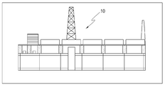
On the other hand, when the drilling operation is completed, as shown in FIG. 1, the
The
On the other hand, the crude oil transferred to the
In other words, not only crude oil but also the sand around the seabed are inhaled during the process of raising the crude oil.
In particular, in sandy terrain waters, the proportion of sand contained in crude oil is substantial.
Accordingly, it is important to remove the sand contained in the crude oil before purifying the crude oil, in order not to damage the equipment of the purification module equipped with the equipment for purifying the crude oil.
That is, if crude oil without sand removal flows directly into the equipment of the refining module, the equipment of the refining module may be buried in sand during the refining process for the crude oil, which may cause serious damage.
Conventionally, there is no precise standard for separating sand from crude oil, and equipment for separating sand from crude oil has not been provided.
As a result, the work efficiency for maintenance of the refining module is increased and the efficiency of the operation is decreased.
Therefore, there is a demand for equipment for efficiently separating sand from crude oil drilled from the sea floor.
Disclosure of Invention Technical Problem [8] Accordingly, the present invention has been made keeping in mind the above problems occurring in the prior art, and an object of the present invention is to provide a process for separating oil- Sander system in which the centrifugal separator and the accumulator are integrated to increase the efficiency of the installation space.
In order to achieve the above-mentioned object, the present invention provides an oil reservoir in which crude oil, which is drilled from the sea floor, is separated and stored by using specific gravity gas, oil, and produced water, A plurality of centrifuges connected to the supply passage for centrifugally separating the produced water, an accumulator integrally formed at a lower portion of each of the centrifuges, for storing sand separated from the centrifugal separator, A vertical flow passage provided between the accumulator and the tray for forming a passage through which the sand falls due to its own weight, and an automatic valve installed in each of the vertical flow passages, Sander system that includes a pre-fabricated water de-sander system.
At this time, it is preferable that a centrifugal oily water and a liquid flow path through which gas is discharged are installed on the upper part of the centrifugal separator.
In addition, it is preferable that a liquid for decelerating the flow rate of the sand discharged from the centrifugal separator is stored in the accumulator.
Further, it is preferable that the centrifuges are arranged in parallel.
The centrifugal separator may further include a water level sensor for sensing the level of the produced water flowing through the supply channel.
In addition, it is preferable that the tray is moved by a conveying means using a roller action such as a roller or a conveyor.
The produced water de-sander system according to the present invention has the following effects.
First, by separating the produced sand from the oil extracted from the oil well, the offshore oil and gas production, which is the refining module of FPSO, can be operated for a long time to prevent the equipment from being damaged by foreign matter including sand. There is an effect that can be.
Thus, the quality of refined crude oil can be increased, and maintenance and maintenance costs for the equipment can be reduced.
Second, the centrifugal separator and the accumulator are integrally formed, thereby reducing the manufacturing cost of the system and maximizing the efficiency of the installation space.
Third, there is an effect that the convenience of the tray movement can be improved by moving the tray using a conveying means such as a conveyor or a roller.
Figure 1 is a side view of a floating offshore structure (FPSO)
2 is a configuration view of a produced water de-sander system according to a preferred embodiment of the present invention.
It is to be understood that the words or words used in the present specification and claims are not to be construed in a conventional or dictionary sense and that the inventor can properly define the concept of a term in order to describe its invention in the best possible way And should be construed in light of the meanings and concepts consistent with the technical idea of the present invention.
Hereinafter, a produced water de-sander system (hereinafter, referred to as a "de-sander system") according to a preferred embodiment of the present invention will be described with reference to FIG.
Crude oil drilled from the bottom of the seabed includes oil, gas and seawater.
This crude oil is stored in an oil reservoir, and then separates each fluid primarily using specific gravity.
That is, produced water is produced at the bottom of the reservoir and oil, gas and so on are placed on the top of the produced water.
At this time, the oil and gas are discharged to a separate place provided on one side of the oil reservoir.
Meanwhile, the produced water remaining in the oil reservoir contains sand drilled from the sea floor and various slurries, and the sand and slurry must be separated and treated.
These sand and slurries not only damage various equipments, but they can also affect the environmental pollution because they are oiled.
As a result, the produced water is separated from the sand and slurry by using a desalter system installed on the top side of the offshore structure.
The Desander system has the technical feature of separating solid particles, such as sand and slurry, from the produced water into separate disposal sites.
2, the desalter system includes a
The
At this time, a
Next, the
At this time, the
The
That is, during the process of centrifugal separation of the produced water supplied to the
At this time, the fluid is separated into oily water containing oil adhered to the sand and gas which is evaporated while the internal pressure of the
At this time, the gas contains hydrocarbons and the like, which may cause toxicity and explosion risk, and therefore must be discharged through the
A
The
That is, when a certain amount of produced water is charged into the
Meanwhile, the
As the operation for separating the sand is performed alternately, the overload of each device is solved, so that the device can be prevented from being overloaded and the safety accident of the worker can be prevented.
That is, the periphery of the
On the other hand, the
Next, the
The
That is, since the
Particularly, the
At this time, a certain amount of water is stored in the
An
Next, the
At this time, the
Next, the
At this time, the
That is, the arrangement structure of the
At this time, an
On the other hand, a conveying means 600 such as a roller or a conveyor is preferably provided below the
This is for facilitating the movement of the sand collected on the
Hereinafter, the operation of the dig sander system constructed as described above will be described.
The
At this time, the branched
The
Thereafter, the produced water introduced into the
Thereafter, the produced water moves to the downstream side of the
At this time, the interior of the
Thereafter, the sand and slurry pushed to the inner peripheral surface side of the
At this time, the oily water is drained through the
At this time, in the process of draining the oily water, the pressure inside the
The noxious gas is also discharged through the
On the other hand, the sand and the slurry fall directly into the
Thereafter, the discharge passage 320 of the
Thereafter, the sand and slurry are collected in the
Meanwhile, after the above-described series of separating operations are performed, in order to continuously perform the separating operation, the system is changed over to one side.
This is to prevent the overload of the system and to eliminate the harmful gas around the
That is, the continuity of the separation operation can be maintained by operating one side system while one system is stopped until the harmful gas is dissolved.
For this purpose, the branched
At this time, the
Thereafter, the sand separated from the
Thereafter, the sand processed in the
As described above, the produced water desalter system according to the present invention can prevent the equipment failure due to sand or the like by separating and removing the sand and slurry contained in the drilled crude oil, thereby improving the quality of the refined oil There are technical features that can be.
Further, since the centrifugal separator and the accumulator are integrally formed, the efficiency of the installation space can be increased and the manufacturing cost can be reduced.
While the present invention has been particularly shown and described with reference to exemplary embodiments thereof, it is evident that many alternatives, modifications and variations will be apparent to those skilled in the art.
100: Supply flow path 200 (200A, 200B): Centrifuge
210: Liquid passage 300 (300A, 300B): Accumulator
400: Tray 500 (500A, 500B): Vertical channel
600: conveying means
Claims (6)
A supply passage through which the produced water is supplied from the oil reservoir;
A plurality of centrifuges connected to the supply passage for centrifugally separating the produced water;
An accumulator integrally formed at a lower portion of each of the centrifuges and storing the sand separated from the centrifugal separator;
A tray installed below the accumulator for collecting sand of the accumulator;
A vertical flow path provided between the accumulator and the tray, the vertical flow path forming a channel through which sand is dropped by its own weight;
And an automatic valve installed in each of the vertical flow paths.
Wherein a centrifugal oily water and a liquid flow path through which gas is discharged are installed on the upper portion of the centrifugal separator.
Wherein a liquid for decelerating the flow rate of the sand discharged from the centrifugal separator is stored in the accumulator.
Wherein the centrifuges are arranged in parallel.
Wherein the centrifugal separator is provided with a water level sensor for sensing the water level of the produced water flowing through the supply channel.
Wherein the tray is moved by a conveying means using a rolling action such as a roller or a conveyor.
Priority Applications (1)
| Application Number | Priority Date | Filing Date | Title |
|---|---|---|---|
| KR1020120146148A KR20140077388A (en) | 2012-12-14 | 2012-12-14 | Produced water de-sander system |
Applications Claiming Priority (1)
| Application Number | Priority Date | Filing Date | Title |
|---|---|---|---|
| KR1020120146148A KR20140077388A (en) | 2012-12-14 | 2012-12-14 | Produced water de-sander system |
Publications (1)
| Publication Number | Publication Date |
|---|---|
| KR20140077388A true KR20140077388A (en) | 2014-06-24 |
Family
ID=51129330
Family Applications (1)
| Application Number | Title | Priority Date | Filing Date |
|---|---|---|---|
| KR1020120146148A KR20140077388A (en) | 2012-12-14 | 2012-12-14 | Produced water de-sander system |
Country Status (1)
| Country | Link |
|---|---|
| KR (1) | KR20140077388A (en) |
Cited By (1)
| Publication number | Priority date | Publication date | Assignee | Title |
|---|---|---|---|---|
| KR20160054329A (en) * | 2014-11-06 | 2016-05-16 | (주)나우이엔에스 | Interworking method of plural centrifuge |
-
2012
- 2012-12-14 KR KR1020120146148A patent/KR20140077388A/en not_active Application Discontinuation
Cited By (1)
| Publication number | Priority date | Publication date | Assignee | Title |
|---|---|---|---|---|
| KR20160054329A (en) * | 2014-11-06 | 2016-05-16 | (주)나우이엔에스 | Interworking method of plural centrifuge |
Similar Documents
| Publication | Publication Date | Title |
|---|---|---|
| EP2176517B1 (en) | Systems and methods for separating hydrocarbons from water | |
| KR101036621B1 (en) | Apparatus for processing drain | |
| CA2989703C (en) | Method and system for subsea separation of produced water | |
| JP2014512469A (en) | Apparatus and method for taking out solid matter in water bottom | |
| KR101302021B1 (en) | Apparatus Processing Drain | |
| KR20140057065A (en) | Produced water de-sander system | |
| KR20140077388A (en) | Produced water de-sander system | |
| CN103449063B (en) | Zero-pollution underwater oil storage system with oil and water displacement function | |
| MXPA06010651A (en) | Automatic tank cleaning system. | |
| KR20140077384A (en) | Produced water de-sander system | |
| CN202729851U (en) | Buoy submergence type floating oil absorption device | |
| KR101357370B1 (en) | Apparatus for treating drain in drill ship and drill ship having the apparatus | |
| NO20120521A1 (en) | Underwater separation systems | |
| KR101774773B1 (en) | Separator for multiphase mixture | |
| US9745024B2 (en) | Recessed barge design | |
| KR20240015772A (en) | Marine Polluted Water Treatment System And Treatment Method Using Hydrocyclone And Compact Flotation Unit | |
| KR20130071740A (en) | Skimmer tank to separate drilling mud | |
| KR101519532B1 (en) | Drilling cutting treatment system for an offshore structure | |
| KR102237989B1 (en) | Apparatus for separating oil-water | |
| KR101572442B1 (en) | Degassing device having oil re-saparaton function | |
| KR101670881B1 (en) | Drilling cutting disposal system and shaleshaker room | |
| KR200481700Y1 (en) | Drilling cutting guider of the offshore structure and drilling cutting disposal module with thw same | |
| KR101584562B1 (en) | Drilling system and drilling offshore structure | |
| KR20160001898U (en) | Marine Plant Drain Apparatus with Coalescer | |
| KR20150076687A (en) | Drain seperation system for drillship |
Legal Events
| Date | Code | Title | Description |
|---|---|---|---|
| WITN | Withdrawal due to no request for examination |