KR20140074789A - Pump magnet housing with integrated sensor element - Google Patents
Pump magnet housing with integrated sensor element Download PDFInfo
- Publication number
- KR20140074789A KR20140074789A KR1020127033978A KR20127033978A KR20140074789A KR 20140074789 A KR20140074789 A KR 20140074789A KR 1020127033978 A KR1020127033978 A KR 1020127033978A KR 20127033978 A KR20127033978 A KR 20127033978A KR 20140074789 A KR20140074789 A KR 20140074789A
- Authority
- KR
- South Korea
- Prior art keywords
- magnet
- pump
- housing
- sensor element
- driven
- Prior art date
Links
- 239000012530 fluid Substances 0.000 claims abstract description 50
- 238000005086 pumping Methods 0.000 claims abstract description 23
- 230000003068 static effect Effects 0.000 claims abstract description 10
- 238000007789 sealing Methods 0.000 claims abstract description 4
- 238000000034 method Methods 0.000 claims description 8
- 238000005259 measurement Methods 0.000 claims description 6
- 238000009736 wetting Methods 0.000 claims description 5
- 230000001939 inductive effect Effects 0.000 claims description 4
- 238000003466 welding Methods 0.000 claims description 4
- 230000008859 change Effects 0.000 claims description 3
- 238000000465 moulding Methods 0.000 claims description 3
- 239000012528 membrane Substances 0.000 claims description 2
- 238000004026 adhesive bonding Methods 0.000 claims 1
- 238000005219 brazing Methods 0.000 claims 1
- 238000002955 isolation Methods 0.000 claims 1
- 231100001261 hazardous Toxicity 0.000 abstract description 2
- 230000008878 coupling Effects 0.000 abstract 1
- 238000010168 coupling process Methods 0.000 abstract 1
- 238000005859 coupling reaction Methods 0.000 abstract 1
- 238000012544 monitoring process Methods 0.000 abstract 1
- 230000004888 barrier function Effects 0.000 description 8
- 239000000463 material Substances 0.000 description 5
- 239000000853 adhesive Substances 0.000 description 3
- 230000001070 adhesive effect Effects 0.000 description 3
- 230000008901 benefit Effects 0.000 description 3
- 238000011065 in-situ storage Methods 0.000 description 3
- 239000002184 metal Substances 0.000 description 3
- 230000003287 optical effect Effects 0.000 description 3
- 230000005355 Hall effect Effects 0.000 description 2
- 238000005266 casting Methods 0.000 description 2
- 239000002131 composite material Substances 0.000 description 2
- 230000003750 conditioning effect Effects 0.000 description 2
- 229920001577 copolymer Polymers 0.000 description 2
- 239000006260 foam Substances 0.000 description 2
- 230000010354 integration Effects 0.000 description 2
- 150000002500 ions Chemical class 0.000 description 2
- 238000003754 machining Methods 0.000 description 2
- 230000002745 absorbent Effects 0.000 description 1
- 239000002250 absorbent Substances 0.000 description 1
- 238000010521 absorption reaction Methods 0.000 description 1
- 230000000712 assembly Effects 0.000 description 1
- 238000000429 assembly Methods 0.000 description 1
- 238000006243 chemical reaction Methods 0.000 description 1
- 239000004020 conductor Substances 0.000 description 1
- 238000007872 degassing Methods 0.000 description 1
- 238000010586 diagram Methods 0.000 description 1
- 238000006073 displacement reaction Methods 0.000 description 1
- 239000000835 fiber Substances 0.000 description 1
- 238000010348 incorporation Methods 0.000 description 1
- 239000000696 magnetic material Substances 0.000 description 1
- 229910001092 metal group alloy Inorganic materials 0.000 description 1
- 239000002245 particle Substances 0.000 description 1
- 239000002861 polymer material Substances 0.000 description 1
- 230000008569 process Effects 0.000 description 1
- 230000005855 radiation Effects 0.000 description 1
Images


Classifications
-
- F—MECHANICAL ENGINEERING; LIGHTING; HEATING; WEAPONS; BLASTING
- F04—POSITIVE - DISPLACEMENT MACHINES FOR LIQUIDS; PUMPS FOR LIQUIDS OR ELASTIC FLUIDS
- F04B—POSITIVE-DISPLACEMENT MACHINES FOR LIQUIDS; PUMPS
- F04B17/00—Pumps characterised by combination with, or adaptation to, specific driving engines or motors
-
- F—MECHANICAL ENGINEERING; LIGHTING; HEATING; WEAPONS; BLASTING
- F04—POSITIVE - DISPLACEMENT MACHINES FOR LIQUIDS; PUMPS FOR LIQUIDS OR ELASTIC FLUIDS
- F04B—POSITIVE-DISPLACEMENT MACHINES FOR LIQUIDS; PUMPS
- F04B53/00—Component parts, details or accessories not provided for in, or of interest apart from, groups F04B1/00 - F04B23/00 or F04B39/00 - F04B47/00
- F04B53/16—Casings; Cylinders; Cylinder liners or heads; Fluid connections
-
- F—MECHANICAL ENGINEERING; LIGHTING; HEATING; WEAPONS; BLASTING
- F04—POSITIVE - DISPLACEMENT MACHINES FOR LIQUIDS; PUMPS FOR LIQUIDS OR ELASTIC FLUIDS
- F04B—POSITIVE-DISPLACEMENT MACHINES FOR LIQUIDS; PUMPS
- F04B17/00—Pumps characterised by combination with, or adaptation to, specific driving engines or motors
- F04B17/03—Pumps characterised by combination with, or adaptation to, specific driving engines or motors driven by electric motors
Abstract
예시적인 자기적으로-구동되는 유체 펌프는 하나 또는 둘 이상의 센서들이 펌핑되는 유체와 간접적으로("비-습윤형") 접촉할 수 있게 하는 한편, 유체 도관 또는 챔버에 장착되고 그리고 유체 경로들 내로 연장하는 센서들에서 일반적으로 필요한 정적인 밀봉부들을 회피할 수 있는 자석 하우징("컵")을 포함한다. 센서들은 유체의 모니터링 또는 펌프의 피드백 제어를 위해서 사용될 수 있을 것이다. 펌프를 제어하는 전자 회로에 센서들을 직접적으로 커플링시킴으로써, 모터 하우징 외부에 위치되는 와이어들의 수가 최소화될 수 있고, 이는 조립체의 내구성을 보다 향상시킨다. 이는 위험한 환경이나 침잠되는 용도들에서 특히 유리하다. 통상적인 펌프들 및 시스템들에 대비하여, 본원에 개시된 펌프들 및 유압식 시스템들은 보다 더 공격적인 펌핑 조건들 하에서 보다 적은 누설을 나타내는 한편, 개선된 펌핑 성능을 제공한다. Exemplary magnetically-driven fluid pumps allow one or more sensors to be in indirect ("non-wet") contact with a fluid to be pumped, while mounted to a fluid conduit or chamber and into fluid paths ("Cup") which is capable of avoiding the static sealing normally required in extending sensors. The sensors may be used for fluid monitoring or feedback control of the pump. By directly coupling the sensors to the electronic circuitry controlling the pump, the number of wires located outside the motor housing can be minimized, which further improves the durability of the assembly. This is particularly advantageous in hazardous environments or in sinking applications. In contrast to conventional pumps and systems, the pumps and hydraulic systems disclosed herein exhibit less leakage under more aggressive pumping conditions while providing improved pumping performance.
Description
관련 출원Related application
본원은 2010년 6월 1일자로 출원된 미국 가특허출원 제 61/396,715 호 및 2011년 6월 1일자로 출원된 미국 특허출원 제 13/151,188 호의 이익 향유 및 우선권을 주장하고, 상기 출원들 전체는 본원에서 참조에 의해서 포함된다.
This application claims the benefit of and priority to U.S. Provisional Patent Application No. 61 / 396,715, filed June 1, 2010, and U.S. Patent Application No. 13 / 151,188, filed June 1, 2011, Quot; is hereby incorporated by reference.
본원 발명은 특히 자기적으로 구동되는 여러 가지 펌프 타입들에 관한 것이다. 보다 구체적으로, 본원 발명은 펌프 기어와 같은 회전 또는 회전-왕복 요소가 자석 하우징("자석 컵") 내에 수용된 피구동(driven) 자석에 연결된 펌프에 관한 것으로서, 자석 하우징 내에서는 펌프에 의해 펌핑되는 유체에 의해서 자석이 습윤된다(wetted). The present invention particularly relates to various pump types that are magnetically driven. More specifically, the present invention relates to a pump connected to a driven magnet in which a rotating or rotating-reciprocating element such as a pump gear is housed in a magnet housing ("magnet cup"), The magnet is wetted by the fluid.
통상적인 유압식(hydraulic) 시스템들은 유체 유동을 강제하기 위한 하나 또는 둘 이상의 펌프들을 종종 포함한다. 많은 그러한 시스템들은 또한 시스템 내에서 유동하는 유체 유동의 압력, 온도, 전도도 등과 같은 여러 가지 매개변수들 중 임의의 매개변수에 대한 센서들 또는 표시장치들을 포함한다. 통상적인 표시장치들은 각각의 매개변수를 직접적으로 나타내는 부르돈(Bourdon) 게이지들, 볼-유량계들, 아날로그 온도계들 등을 포함한다. "센서"는 일반적으로 감지된 매개변수들(예를 들어, 압력 또는 온도)을 대응하는 신호(예를 들어, 전기적 또는 광학적 신호)로 변환하는 변환기 등을 포함한다. 일반적으로, 센서들은 또한, 예를 들어, 제어 회로들에서의 사용을 위해서 또는 매개변수의 측정을 제공하기 위해서, 필요에 따라, 변환기들로부터 직접적으로 데이터를 수신하고 그리고 다른 전자장치들에서의 사용을 위해서 데이터를 프로세싱하는 전자 회로를 포함한다. 측정은, 예를 들어, 매개변수의 디스플레이(예를 들어, LED 디스플레이)를 위해서 사용될 수 있다. 예시적인 제어 회로는 펌프에 파워를 공급하는(powering) 모터 또는 액추에이터의 피드백 제어 또는 다른 제어를 실행하도록 연결되고 구성된 제어기를 포함한다. Conventional hydraulic systems often include one or more pumps to force fluid flow. Many such systems also include sensors or indicators for any of a variety of parameters such as pressure, temperature, conductivity, etc. of fluid flow flowing within the system. Conventional displays include Bourdon gauges, ball-flow meters, analog thermometers, and the like, which directly represent each parameter. A "sensor" generally includes a transducer, etc., that converts the sensed parameters (e.g., pressure or temperature) into corresponding signals (e.g., electrical or optical signals). In general, sensors may also receive data directly from transducers, for example, for use in control circuits or to provide a measurement of parameters, and may be used for other electronic devices Lt; RTI ID = 0.0 > and / or < / RTI > The measurement can be used, for example, for the display of parameters (e.g. LED display). An exemplary control circuit includes a controller coupled and configured to perform feedback control or other control of a motor or actuator that powers the pump.
펌프를 포함하는 유압식 시스템들에서, 펌프는 전형적으로 분리된 단독형(discrete stand-alone) 요소이며, 이는 펌프가 다른 요소들로부터 독립적으로 제조되고 그리고 주문자 상표 부착 생산자(OEM)의 자체적인 시스템으로 통합하기 위해서, 유체 도관들 등과 같은 다른 요소들과 함께, 주문자 상표 부착 생산자에게 공급된다는 것을 의미한다. 유사하게, 센서들 및 표시장치들은 또한 일반적으로, 여러 가지 용도들 중 임의 용도에서 주문자 상표 부착 생산자들에 의한 사용을 위해서 구성되고 판매되는, 분리된 요소들이다. 이러한 구성들은, 특히 공간이 구속 인자가 되지 않는 경우에, 대부분의 유압식 회로들에서 양호하게 작동한다. 그러나, 통상적인 분리형 요소를 유압식 회로에 연결하는 것은 일반적으로 일부 종류의 정적인 밀봉부(static seal)를 필요로 한다. 영구적인(permanent) 적용예들의 경우에, 요소들이 제위치로 용접된다. 일반적으로 유효한 정적인 밀봉부를 제공하지만, 제위치에 용접된 요소를 제거하는 것은 매우 어렵고 또는 불가능하다. 대부분은 아니더라도 많은 적용예들에서, 정적인 밀봉부(들)은, 때때로 시스템으로부터 요소가 제거될 수 있게 허용하도록 구성된다. 이러한 목적을 위한 예시적인 정적인 밀봉부로서 엘라스토머계 O-링, 링 밀봉부, 또는 가스켓 등이 있다. 불행하게도, 정적인 밀봉부들의 이러한 타입들 또는 유사한 타입들은 높은 누설 가능성을 나타낸다. 누설 위험은 잠수형 시스템들, 위험한 유체들을 취급하는 시스템들, 및 가혹한 조건들 하에서 동작되어야 하는 또는 극히 오랜 시간 동안 문제 없이 동작되어야 하는 시스템들에서 심각한 문제가 될 수 있다. In hydraulic systems including pumps, the pump is typically a discrete stand-alone element, which is manufactured independently of the other elements and is the original system of the original equipment manufacturer (OEM) Together with other components, such as fluid conduits, for integration purposes. Similarly, sensors and display devices are also generally separate components that are configured and sold for use by custom manufacturer producers in any of a variety of applications. These configurations work well in most hydraulic circuits, especially when space is not the limiting factor. However, connecting a conventional removable element to a hydraulic circuit generally requires some sort of static seal. In the case of permanent applications, the elements are welded in place. Generally, it provides an effective static seal, but it is very difficult or impossible to remove welded elements in place. In many, if not most, applications, the static seal (s) are configured to allow elements to be removed from the system from time to time. Exemplary static seals for this purpose include elastomeric O-rings, ring seals, gaskets, and the like. Unfortunately, these types of static seals or similar types exhibit high leakage potential. Leakage hazards can be a serious problem in submerged systems, systems handling hazardous fluids, and systems that must be operated under harsh conditions or that must operate without problems for an extremely long period of time.
유압식 회로들의 특정 적용예들에서, 펌프들, 표시장치들, 센서들, 회로들 등과 같은 요소들이 가능한 한 많이 소형화될 것이 요구되고 있다. 다른 적용예들에서는, 요소들의 내구성을 높은 정도로 높일 것이 요구되고 있다. 종종, 소형화 및 내구성(ruggedness) 강화 모두가 동시에 달성되어야 한다. 불행하게도, 심한 소형화는 보다 양호한 내구성 강화를 동시에 달성하는데 종종 방해가 된다. 이러한 것은 일반적으로 유압식 시스템들에서뿐만 아니라 그러한 시스템에서 사용되는 펌프들 및 다른 요소들에 대해서도 마찬가지로 적용된다. In certain applications of hydraulic circuits, it is desired that elements such as pumps, displays, sensors, circuits, etc. be miniaturized as much as possible. In other applications, it is desired to increase the durability of the elements to a high degree. Often, both miniaturization and enhanced ruggedness must be achieved at the same time. Unfortunately, severe miniaturization is often a hindrance to achieving better durability enhancement at the same time. This applies not only to hydraulic systems in general, but also to pumps and other elements used in such systems.
유압식 시스템의 크기를 줄이기 위한 및/또는 내구성 강화를 위한 노력은 펌프들 및 센서들과 같은 특정의 분리된 요소들의 이용 상의 어려움을 실질적으로 증대시킬 수 있다. 하나의 해결 난제는, 펌프 하우징의 내부를 외부 환경으로부터 격리시키는 또는 외측으로부터 유압 유동 경로 내로 연장하는 센서 주위를 밀봉하는 정적인 밀봉부들과 같은 적절한 밀봉부들을 형성하고 유지하는 것과 관련한 어려움을 포함한다. 다른 해결 난제는 시스템 내에서 요소들을 서로 상당히 근접하여 배치하고 연결하는 것으로부터 유발된다. 예를 들어, 통상적인 독립형 압력 센서를 소형화된 펌프의 유입구 또는 배출구에 배치하는 것은 너무 많은 공간을 차지하는 일그러진(contorted) 구성을 초래할 수 있고 그리고 그러한 일그러진 구성에서 요소는 해당 위치로 본질적으로 억지로 집어 넣어진다. 이러한 구성들은 요소들 및/또는 그들의 각각의 하우징들에 과다한 응력을 인가할 수 있고, 밀봉부들을 손상시킬 수 있으며, 그리고 요소들의 전체적인 신뢰도 및/또는 동작가능한 수명을 감소시킬 수 있다. 사실상, 작은 크기 및 중요한(critical) 밀봉에 대한 요건들로 인해서 유압식 시스템에서 통상의 유체 센서들을 이용하지 못할 수 있을 것이다. Efforts to reduce the size of the hydraulic system and / or enhance durability can substantially increase the difficulty in using certain discrete elements such as pumps and sensors. One challenge is the difficulty associated with forming and maintaining suitable seals, such as static seals that seal around the sensor, isolating the interior of the pump housing from the external environment or extending from the outside into the hydraulic flow path . Another difficulty arises from placing and connecting elements in close proximity to each other within the system. For example, disposing a conventional stand-alone pressure sensor at the inlet or outlet of a miniaturized pump can result in a contorted configuration that takes up too much space, and in such a distorted configuration, the element is essentially forced into position Loses. Such arrangements can exert excessive stress on the elements and / or their respective housings, can damage the seals, and reduce the overall reliability and / or operable life of the elements. In fact, the requirements for small size and critical sealing may not allow the use of conventional fluid sensors in hydraulic systems.
본원에 기술된 펌프 시스템들은 소형화 및 내구성 강화를 요구하는 특정 용도들에서 사용되는 기어 펌프들에서의 가능한 개선 사항들을 탐색하는 동안에 개발되었다. 구체적으로, 펌프의 물리적 압력 배리어("하우징")의 일부로서 하나 또는 둘 이상의 센서들을 포함하는 것은, 부가적인 유압식 연결부들을 배제함으로써, 상당히 더 작은 펌프-센서 조합들을 제공하면서도 임의의 부가적인 누설 가능성의 영향들을 완화시킨다. The pump systems described herein have been developed while exploring possible improvements in gear pumps used in specific applications requiring miniaturization and durability enhancement. Specifically, including one or more sensors as part of the pump's physical pressure barrier ("housing") eliminates additional hydraulic connections, thereby providing significantly smaller pump-sensor combinations, .
(기어 펌프 내의 구동 기어 및 피구동 기어의 조합과 같은) 회전 펌핑 부재를 자기적으로 작동시키기 위해서, 회전 펌핑 부재는 자석 구동장치에 의해서 구동될 때 길이방향 축 상에서 회전하도록 구성된 피구동 자석에 커플링된다. 피구동 자석은 자석 하우징("자석 컵") 내에 밀봉식으로 수용되고, 상기 자석 하우징은 펌핑되는 유체에 의해서 자석이 잠겨질(bathed) 수 있게 하고 그리고 자석이 구동될 때 외부 환경으로부터 격리될 수 있게 한다. 이는 유체 경로 내에서 펌프의 피구동 부분들의 위치를 유지하고 그리고 누설이 쉬운 동적인 밀봉부를 이용할 필요성을 배제한다. 로터 환경을 스테이터 환경으로부터 격리시킬 수 있는 능력은 자기적으로-구동되는 펌프들의 주요 장점이다. In order to magnetically actuate a rotary pumping member (such as a combination of a drive gear and a driven gear in a gear pump), the rotary pumping member is coupled to a driven magnet configured to rotate on a longitudinal axis when driven by a magnet drive . The driven magnet is enclosed in a magnet housing ("magnet cup"), which allows the magnet to be bathed by the fluid being pumped and can be isolated from the external environment when the magnet is driven Let's do it. This avoids the need to maintain the position of the driven parts of the pump in the fluid path and to use a dynamic seal that is easy to leak. The ability to isolate the rotor environment from the stator environment is a major advantage of magnetically-driven pumps.
일반적으로, 자기적으로-구동되는 펌프에 센서를 부가하는 것은 (피드백 제어-타입 센서의 경우에) 펌프의 동작을 제어하거나 (유체 모니터링-타입 센서의 경우에) 데이터를 통신 및/또는 저장하는 전자장치들과 센서 사이의 전기적 연결을 어떻게 처리하는지와 관련한 해결 난제를 제시한다. 유선형 전기적 연결부들을 이용하는 일부 유체 센서들은, 와이어들이 유체 격납(containment) 벽 내의 홀("관통-홀")을 통과하여야 하도록, 디자인되고, 그에 따라 유체가 전자장치들과 접촉하여 손상시킬 수 있는 가능성을 방지하기 위한 밀봉부를 필요로 한다. 관통 홀들 및 밀봉부들의 부가는 펌프를 덜 견고하게 만드는 경향이 있는데, 이는 모터 하우징 내로 진입하는 각각의 와이어가 잠재적인 누설 지점을 부가하기 때문이고, 그러한 누설 지점에서 수분 또는 환경적 오염물질들이 모터 전자장치들로 접근할 수 있을 것이다. 자석 컵 내에 하나 또는 둘 이상의 센서 변환기들을 포함시키는 것은 센서 기능(들)을 제공하기 위해서 분리된 요소(들)을 이용하여야 할 필요성을 제거하고, 그에 따라 자석 컵 내에 하나 또는 둘 이상의 센서 변환기들을 포함시키지 않는 경우에 필요할 수 있는 정적인 밀봉부(들)을 배제한다. 본원에 개시된 자석 컵들의 특정 실시예들은 하나 또는 둘 이상의 센서들이 펌핑된 유체와 간접적으로 접촉할 수 있게 한편, 유체 도관 또는 챔버에 장착되고 그리고 유체 경로 내로 연장하는 센서들에서 일반적으로 요구되는 정적인 밀봉부들을 회피할 수 있게 한다. In general, adding a sensor to a magnetically-driven pump can either control the operation of the pump (in the case of a feedback control-type sensor) or communicate and / or store data (in the case of a fluid monitoring-type sensor) And presents a solution to the problem of how to handle the electrical connection between the electronic devices and the sensor. Some fluid sensors utilizing streamlined electrical connections are designed so that the wires must pass through holes ("through-holes") in the fluid containment wall, and thus the ability of the fluid to contact and damage electronic devices It is necessary to provide a sealing portion for preventing the leakage. The addition of through-holes and seals tends to make the pump less robust because each wire entering the motor housing adds a potential leakage point and at such a point of leakage, You will be able to access electronic devices. The inclusion of one or more sensor transducers in the magnetic cup eliminates the need to use separate element (s) to provide the sensor function (s), thereby accommodating one or more sensor transducers in the magnetic cup (S) that may be required if not allowed. Certain embodiments of the magnetic cups disclosed herein may be used to provide one or more sensors that are capable of indirect contact with a pumped fluid while being mounted on a fluid conduit or chamber and having a static Thereby making it possible to avoid the seals.
또한, 자석 컵 내에 하나 또는 둘 이상의 센서 변환기들을 포함시키지 않는 경우에 단독형 요소(들)의 하우징(들)에 의해서 점유되게 될 공간의 부피가 감소되고, 결과적으로 상당히 더 콤팩트한(compact) 조립체를 초래한다. 센서 전자장치들을 자기 컵의 말단-단부 벽의 외측에 장착되는 인쇄회로기판 상에 통함시킴으로써, 예를 들어 (센서 변환기가 회로 기판에 장착되고 그리고 자석 컵의 벽을 통해서 각각의 매개변수를 감지하는 상태에서), 조립체들이 보다 더 콤팩트하게 그리고 보다 더 신뢰할 수 있게 제조된다. 이러한 방식에서, 센서 전자장치들이, 최소 외부 배선으로 또는 외부 배선 없이, 예를 들어, 자석-구동 스테이터를 포함하는 하우징 내부에 위치된 인쇄회로기판 상에 위치된 모터-제어 전자장치들에 직접적으로 커플링될 수 있다. 센서(들)을 자석 컵의 벽 내에 통합함으로써, 보다 더 적은 와이어들이 모터 하우징 외부에 위치되기 때문에, 전체 펌프 조립체가 통상적인 펌프 시스템들 보다 더 큰 내구성을 가지게 된다. 이러한 것은 유해한 환경 또는 침잠된 적용예들에서 특히 유리하다. Also, the volume of the space to be occupied by the housing (s) of the single element (s) when the one or more sensor transducers are not included in the magnetic cup is reduced, resulting in a significantly more compact assembly . By allowing the sensor electronics to be mounted on a printed circuit board mounted outside the end-end wall of the magnetic cup, it is possible, for example, for the sensor transducer to be mounted on the circuit board and to sense each parameter through the wall of the magnetic cup , The assemblies are manufactured to be more compact and more reliable. In this way, the sensor electronics can be connected directly to the motor-control electronics located on a printed circuit board located inside the housing, including, for example, a magnet-driven stator, with minimal external wiring or without external wiring Lt; / RTI > By integrating the sensor (s) within the wall of the magnet cup, the entire pump assembly has greater durability than conventional pump systems, since fewer wires are located outside the motor housing. This is particularly advantageous in harmful environments or in submerged applications.
본원에 도시된 예시적인 실시예들이 기어 펌프들이나, 개시된 감지 장치들과 부합되는 펌핑 시스템들은 제어 펌프들로 한정되지 않는다. 오히려, 그들은 하우징 내에 수용된 그리고 영구 자석에 커플링된 적어도 하나의 이동가능한 펌프 요소를 가지는 여러 가지 타입들의 펌프들 중 임의의 펌프를 포함하고, 상기 이동가능한 펌프 요소는 하우징의 외부에서 기원하고 그리고 하우징의 벽들을 통해서 자석으로 지향되는 자기력에 의해서 구동된다. 일반적으로, 자석은 자석 하우징 또는 자석 컵으로 지칭되는 하우징의 부분 내에 수용된다. 이동가능한 요소가 회전(rotary) 요소인 펌프들에서, 자석이 회전 자기장 내에 배치될 때, 그 자석이 길이방향 자석 축을 중심으로 자석 컵 내에서 회전되도록, 자석 및 자석 컵이 구성된다. 이러한 목적을 위해서, 피구동 자석은 일반적으로 실질적으로 원통형인 형상을 가지고 그리고 상기 자석 컵은 피구동 자석을 수용하는 실질적으로 중공형인 원통형(캔(can)-유사) 구성을 가진다. 피구동 자석은 모터의 전기자(armature)에 커플링된 구동 자석에 의해서 구동될 수 있고, 또는 자석 컵 외부에 위치된 구동 스테이터에 의해서 구동될 수 있다. 구동 자석에 의해서 또는 스테이터에 의해서 생성된 자력 라인들(lines of magnetic force)은 자석 컵의 벽을 통과하고 그리고 피구동 자석에 유도적으로 커플링된다. 펌프의 작동 중에, 자체 축을 중심으로 하는 피구동 자석의 회전을 강제하도록 이러한 자력의 라인들이 지향되고, 이는 회전 펌프 요소의 회전을 유발한다. 기어 펌프에서, 회전 펌프 요소는 "구동 기어"로서 지칭되고, 상기 구동 기어는 대응하는 피구동 기어와 서로 맞물린다. 구동 기어가 회전될 때, 그러한 회전은 피구동 기어의 대응하는 반대-회전을 유발한다. 조합된 기어 회전들은 펌핑력을 생성한다. 기어 펌프는, 예를 들어, 일반적으로 "공동(cavity) 스타일"로 공지된 것일 수 있고, 또는, 예를 들어, "흡입 슈(suction shoe)"를 포함할 수 있고, 또는 이들의 복합형(hybrid)일 수 있다. The exemplary embodiments shown herein are not limited to gear pumps or pumping systems that are compatible with the disclosed sensing devices are control pumps. Rather, they include any of the various types of pumps housed within the housing and having at least one movable pump element coupled to the permanent magnet, the moveable pump element originating from the exterior of the housing, And is driven by a magnetic force directed to the magnet through the walls of the magnet. Generally, a magnet is housed within a portion of a housing, referred to as a magnet housing or a magnet cup. In pumps where the movable element is a rotary element, a magnet and a magnet cup are configured such that when the magnet is placed in the rotating magnetic field, the magnet is rotated in the magnet cup about the longitudinal magnet axis. For this purpose, the driven magnet generally has a substantially cylindrical shape and the magnetic cup has a cylindrical (can-like) configuration that is substantially hollow to accommodate the driven magnet. The driven magnet can be driven by a drive magnet coupled to the armature of the motor, or driven by a drive stator located outside the magnetic cup. Lines of magnetic force generated by the drive magnet or by the stator are inductively coupled through the wall of the magnet cup and to the driven magnet. During operation of the pump, these lines of magnetic force are directed to force rotation of the driven magnet about its own axis, which causes rotation of the rotary pump element. In a gear pump, a rotary pump element is referred to as a "drive gear ", which meshes with a corresponding driven gear. When the drive gear is rotated, such rotation causes a corresponding counter-rotation of the driven gear. The combined gear rotations produce a pumping force. The gear pump may, for example, be generally known as a "cavity style ", or may include, for example, a" suction shoe " hybrid.
피구동 자석에 커플링되는 이동가능한 펌프 요소를 포함하는 다른 타입의 펌프로서 피스톤 펌프가 있다. 피스톤 펌프들의 일부 구성들에서, 피스톤은 자기적으로 구동됨에 따라 회전 및 선형 왕복 운동 모두를 경험한다. 펌프들의 다른 예시적인 타입들은 원심 펌프들, 로브(lobe) 펌프들, 또는 하우징 내에 압력-순응형(compliant) 부재를 가지는 펌프들을 포함한다. Another type of pump comprising a movable pump element coupled to a driven magnet is a piston pump. In some configurations of piston pumps, the piston experiences both rotational and linear reciprocating motion as it is magnetically driven. Other exemplary types of pumps include centrifugal pumps, lobe pumps, or pumps having a pressure-compliant member in the housing.
전술한 바와 같이, 펌프 하우징은 펌프의 물리적 압력 배리어 즉, 펌프의 내부를 그 외부 환경으로부터(또는 그 반대로) 분리시키는 물리적 배리어를 구성한다. 펌프 하우징의 내부로부터 물리적 배리어를 가로지르는 유체의 탈출은 누설을 구성한다. 통상적인 펌프들 및 시스템들에 대비하여, 본원에서 기술된 펌프들 및 유압식 시스템들은 보다 더 공격적인 펌핑 조건들 하에서 보다 적은 누설을 나타내는 한편, 보다 더 긴 기간에 걸쳐 개선된 펌핑 성능을 제공한다. As described above, the pump housing constitutes a physical barrier that separates the pump's physical pressure barrier, i.e., the interior of the pump from its external environment (or vice versa). The escape of fluid across the physical barrier from the interior of the pump housing constitutes leakage. In contrast to conventional pumps and systems, the pumps and hydraulic systems described herein exhibit less leakage under more aggressive pumping conditions while providing improved pumping performance over a longer period of time.
자기 컵이 펌핑 하우징의 일부를 구성하기 때문에, 본원 발명의 많은 실시예들에서, 적어도 하나의 센서는 펌핑되는 유체에 의해서 습윤되지 않도록 자석 컵의 벽 내로 통합된다. 일체형 센서가 독립된, 분리형의 요소 대신에 본질적으로 컵의 일부로서 기능하는 방식이 되도록, 그러한 "일체형 센서"가 자기 컵과 연관된다. 일체형 센서는 자석 컵의 벽 또는 벽의 일부를 가로질러, 또는 자석 컵의 벽에 커플링된 벽 또는 다른 유체 배리어를 가로질러 감지되는 각각의 매개변수들에 대해서 정량적으로 반응할 수 있는 여러 가지 센서들 중 임의의 센서이다. 센서(들)은 압력 센서들, 온도 센서들, 또는 다른 센서들, 예를 들어, 전도도 센서들, 비저항 센서들, 혼탁도(turbidity) 센서들, 유량(점도) 센서들, pH 센서들, 용존 가스 센서들, 또는 혼탁도, 용존 이온들 및 광학적 흡수와 같은 다른 유체 변수들의 센서들, 또는 펌프 모터의 요소들의 회전을 검출하기 위한 센서들 중 하나 또는 둘 이상일 수 있다. 전도도 센서는, 예를 들어, "건조 작동(running dry)" 상태의 이벤트(event)에서 펌프를 중단시키기 위해서 사용될 수 있다. 예를 들어, 모터 제어기가 센서를 구비하지 않는 경우에, 회전 방향을 감지하기 위해서 또는 펌핑 요소의 회전이 조금이라도 발생하는지의 여부를 감지하기 위해서, 회전 센서가 이용될 수 있을 것이다. 예시적인 회전 센서는 홀-효과(Hall-effect)에 기초한다. 용존 가스 센서는 탈가스 시스템을 제어하기 위해서 이용될 수 있을 것이다. 예시적인 센서 타입들은 스트레인 게이지 센서들, 용량성(capacitive) 센서들, 저항 센서들, 압전 센서들 및 이온 특정 전극들(ion-specific electrodes)과 같은 전극들을 포함한다. 센서들은 통상적인 전도체들(와이어들, 및 핀들 등)에 의해서, 또는 센서의 타입 및 일반적인 구성에 의해서 허용되는 경우에, 무선 연결들에 의해서 다른 전자장치들에 연결될 수 있다. 다른 홀-효과 센서들은 하나 또는 둘 이상의 내부 자기 요소들의 기계적인 운동을 검출한다. 유도 센서들은, 예를 들어, 미세하게-위치된 변위들(fine-positioned displacement) 및/또는 음향 신호들을 측정하기 위한 보이스 코일을 포함한다. 다른 예시적인 유도 센서는 RF 신호들을 수신 및/또는 송신한다. In many embodiments of the present invention, at least one sensor is incorporated into the wall of the magnet cup so that it is not wetted by the fluid being pumped, because the magnetic cup constitutes part of the pumping housing. Such an "integral sensor" is associated with the magnetic cup so that the integral sensor is in a manner that essentially acts as part of the cup instead of an independent, discrete element. The integrated sensor can be used to detect a variety of sensors that can react quantitatively across each wall or wall of a magnetic cup or across a wall or other fluid barrier coupled to a wall of a magnetic cup, / RTI > The sensor (s) may include pressure sensors, temperature sensors, or other sensors, such as conductivity sensors, resistivity sensors, turbidity sensors, flow (viscosity) Gas sensors, or other fluid variables such as turbidity, dissolved ions and optical absorption, or sensors for detecting the rotation of elements of the pump motor. The conductivity sensor can be used, for example, to stop the pump in an event of a "running dry" state. For example, in the case where the motor controller does not have a sensor, a rotation sensor may be used to sense the direction of rotation, or to detect whether rotation of the pumping element occurs at all. An exemplary rotation sensor is based on Hall-effect. Dissolved gas sensors may be used to control the degassing system. Exemplary sensor types include electrodes such as strain gauge sensors, capacitive sensors, resistance sensors, piezoelectric sensors, and ion-specific electrodes. The sensors may be connected to other electronic devices by wireless connections, by conventional conductors (such as wires and pins) or, if allowed by the type and general configuration of the sensor. Other Hall-effect sensors detect the mechanical motion of one or more internal magnetic elements. Inductive sensors include, for example, a voice coil for measuring fine-positioned displacements and / or acoustic signals. Other exemplary inductive sensors receive and / or transmit RF signals.
본원에서 제시된 실시예들에서 센서들이 자석 컵의 말단-단부 벽에 장착되는 것으로 설명되어 있지만, 센서들의 위치는 자석 컵의 특별한 벽으로 제한되지 않고, 심지어는 자석 컵으로 제한되는 것도 아니다. 예를 들어, 센서(들)은 (예를 들어, 유입구 압력을 감지하기 위한) 자석 컵의 펌프-유입구 영역 또는 (예를 들어, 배출구 압력을 감지하기 위한) 자석 컵의 펌프-배출구 영역에 위치될 수 있다. 자석 컵의 벽에 또는 펌프 하우징의 다른 영역에 센서를 장착하는, 그에 따라 일체형 센서를 생성하는 예시적인 구성은, 직접 용접되는(direct welded), 개별 멤브레인(separate membrane)이 용접되는, 오버몰딩되는(over-molded), 접착-장착되는, 제위치에 정적으로 밀봉되는, 클램핑되는, 기계적으로 결합되는, 그리고 몰딩 또는 캐스팅에 의해서 벽 내로 직접적으로 통합되는 것을 포함한다. 많은 타입들의 센서들이 펌프 내의 유체와 실제로 접촉하지 않는다. 예를 들어, 압력 센서에 기초하는 스트레인-게이지는 얇은-벽의 자석 컵의 벽을 통해서 또는 자석 컵의 국소적으로 보다 더 얇은 영역을 통해서 압력을 감지할 수 있다. 그러한 센서 변환기는 자석 컵의 "천공되지 않은" 벽에 직접적으로 커플링될 수 있다. 용량성 센서를 장착하기 위한 바람직한 방법은 사출-성형된 폴리머계 자석 컵 또는 비-자성 금속의 벽(예를 들어, 말단-단부 벽)에 저항 용접하는 것이다. Although the sensors are described as being mounted on the end-to-end walls of a magnetic cup in the embodiments presented herein, the position of the sensors is not limited to a particular wall of the magnetic cup, nor is it limited to a magnetic cup. For example, the sensor (s) may be located in the pump-inlet region of the magnet cup (e.g., to sense inlet pressure) or the pump-outlet region of the magnet cup (e.g., to sense outlet pressure) . An exemplary configuration for mounting sensors on a wall of a magnet cup or other area of the pump housing thereby creating an integral sensor is an overmolding process in which a separate membrane is welded, clamped, mechanically coupled, and directly integrated into the wall by molding or casting. The term " over-molded " Many types of sensors do not actually make contact with the fluid in the pump. For example, a strain-gauge based on a pressure sensor can sense pressure through the wall of a thin-walled magnetic cup or through a locally thinner region of the magnetic cup. Such a sensor transducer may be coupled directly to the "perforated" wall of the magnet cup. A preferred method for mounting a capacitive sensor is resistance welding to an injection-molded polymeric magnet cup or a wall of non-magnetic metal (e.g., end-end wall).
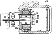
도 1은 펌프 헤드 및 하우징을 포함하는 자기적으로-구동되는 펌프의 실시예의 관상 단면을 도시한 단면도로서, 센서 변환기가 자석 컵의 벽 내로 통합되고 그리고 회로 기판에 직접적으로 연결되는 것을 도시한, 단면도이다.
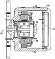
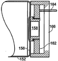
도 2는, 펌프 헤드 및 하우징을 포함하는, 콤팩트한 자기적으로-구동되는 펌프의 실시예의 관상 단면을 도시한 도면으로서, 센서 변환기가 펌핑되는 유체에 의해서 습윤되지 않도록 자석 컵의 벽들 내의 건성 공동 내에 배치되는 것을 도시하고, 일체형 센서 변환기가 인접한 회로 기판에 직접적으로 배선될 수 있고 또는 인접한 전기 요소들과 무선으로 통신할 수 있는 것을 도시한, 단면도이다.
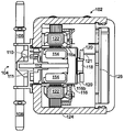
도 3은 펌프 헤드 및 하우징을 포함하는 자기적으로-구동되는 펌프의 실시예의 관상 단면을 도시한 단면도로서, 센서 변환기가 자석 컵의 벽 내로 통합되고, 그리고 센서 변환기의 건성 측벽 부분이 회로 기판에 직접적으로 연결되는 것을 도시한, 단면도이다.
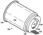
도 4는, 예를 들어 도 3에 도시된 실시예에서 사용될 때의, 자석 컵의 예시적인 실시예의 제 1의 사시도를 도시한 도면으로서, 일체형의 센서 변환기가 환형 회로 기판에 직접적으로 연결되는 것을 도시한, 사시도이다.
도 5는 도 4에 도시된 자기 컵의 제 2의 사시도이다.
도 6은 도 4에 도시된 자기 컵의 말단 단부에서 요소들을 도시한 제 1 단면도이다.
도 7은 인-시츄(in-situ) 피구동 자석을 또한 도시한 도 4에 도시된 자기 컵의 제 3 사시도이다.
도 8은 인-시츄 피구동 자석을 또한 도시한 도 4에 도시된 자기 컵의 제 2 단면도이다.
도 9는 도 4의 자기 컵의 동축적인 요소들을 도시한 분해 사시도이다.
도 10은 도 2에 도시된 자기 컵의 다른 실시예의 제 1 사시도이다.
도 11은 도 10에 도시된 자기 컵의 제 2 사시도이다.
도 12는 도 10에 도시된 자기 컵의 말단 단부의 제 1 단면도로서, 센서 변환기가 자기 컵의 말단-단부 벽 내의 건성 공동 내에 배치될 수 있고 그리고 인접한 인쇄 회로 기판에 편리하게 배선될 수 있는, 단면도이다.
도 13은 인-시츄 피구동 자석을 도시한 도 10에 도시된 자기 컵의 제 3 사시도이다.
도 14는 피구동 자석의 단면도를 포함하는, 도 10에 도시된 자기 컵의 제 2 단면도이다.
도 15는 도 13의 자기 컵의 동축적인 요소들을 도시한 분해도이다.
도 16은 자석 컵의 실시예의 사시도로서, 센서(들)이 측벽 내로 통합되는 것을 도시한, 사시도이다.
도 17은 자석 컵의 실시예의 측면도로서, 정적인 밀봉부를 이용하여 센서가 자석 컵의 말단-단부 내로 통합되는 것을 도시한 측면도이다.
도 18은 도 17에 도시된 자석 컵 및 밀봉된-센서 실시예의 분해도이다.
도 19는 유체 펌프를 모니터링하고 제어하기 위해서 이용될 수 있는 예시적인 피드백-제어 시스템의 하드웨어 요소들 및 소프트웨어 요소들을 도시한 블록도이다. BRIEF DESCRIPTION OF THE DRAWINGS Figure 1 is a cross-sectional view showing a coronal cross section of an embodiment of a magnetically-driven pump including a pump head and a housing, showing that the sensor transducer is integrated into the wall of the magnet cup and directly connected to the circuit board, Sectional view.
Figure 2 shows a tubular cross-section of an embodiment of a compact magnetically-driven pump, including a pump head and a housing, in which the sensor converter is placed in a dry cavity in the walls of the magnet cup And that the integrated sensor transducer can be directly wired to an adjacent circuit board or communicate wirelessly with adjacent electrical elements.
Figure 3 is a cross-sectional view of a corrugated cross section of an embodiment of a magnetically-driven pump including a pump head and a housing in which the sensor transducer is integrated into the wall of the magnet cup and the dry side wall portion of the sensor transducer Which are connected directly to each other.
Figure 4 shows a first perspective view of an exemplary embodiment of a magnetic cup, for example when used in the embodiment shown in Figure 3, in which an integral sensor transducer is directly connected to the annular circuit board FIG.
Figure 5 is a second perspective view of the magnetic cup shown in Figure 4;
Figure 6 is a first cross-sectional view of the elements at the distal end of the magnetic cup shown in Figure 4;
Figure 7 is a third perspective view of the magnetic cup shown in Figure 4 also showing an in-situ driven magnet.
Figure 8 is a second cross-sectional view of the magnetic cup shown in Figure 4 also showing the in-situ driven magnet.
Figure 9 is an exploded perspective view showing the coaxial elements of the magnetic cup of Figure 4;
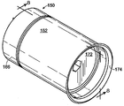
Figure 10 is a first perspective view of another embodiment of the magnetic cup shown in Figure 2;
11 is a second perspective view of the magnetic cup shown in Fig.
Fig. 12 is a first cross-sectional view of the distal end of the magnetic cup shown in Fig. 10, in which the sensor transducer can be disposed within the dry cavity within the end-end wall of the magnetic cup and conveniently wired to an adjacent printed circuit board; Sectional view.
Figure 13 is a third perspective view of the magnetic cup shown in Figure 10 showing the in-situ driven magnet.
14 is a second sectional view of the magnetic cup shown in Fig. 10, including a sectional view of the driven magnet.
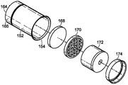
Figure 15 is an exploded view showing the coaxial elements of the magnetic cup of Figure 13;
Figure 16 is a perspective view of an embodiment of a magnetic cup, showing the sensor (s) integrated into the sidewall;
Figure 17 is a side view of an embodiment of a magnetic cup, illustrating the incorporation of the sensor into the end-end of the magnet cup using a static seal.
18 is an exploded view of the magnetic cup and seal-sensor embodiment shown in Fig.
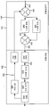
19 is a block diagram illustrating the hardware components and software components of an exemplary feedback-control system that may be utilized to monitor and control a fluid pump.
본원 발명의 전술한 그리고 부가적인 목적들, 특징들, 및 장점들은 첨부 도면들을 참조하여 개진되는 이하의 상세한 설명으로부터 보다 더 명료해질 것이다.BRIEF DESCRIPTION OF THE DRAWINGS The foregoing and additional objects, features, and advantages of the present invention will become more apparent from the following detailed description, taken in conjunction with the accompanying drawings.
도 1은 드라이버 부분(12) 및 펌프 헤드(14)를 포함하는 펌프 조립체(10)의 실시예를 도시한다. 펌프 헤드(14)는 유입구 포트(16), 배출구 포트(18), 구동 기어(20), 샤프트(22), 피구동 자석(24), 및 자석 컵(26)을 포함한다. 자석 컵(26)은 드라이버 부분(12)의 내부에 위치된다. 자석 컵(26)은 피구동 자석(24)을 둘러싸고 피구동 자석(24)과 동축적인 측벽(26a) 및 말단-단부 벽(26b)을 구비한다. 측벽(26a) 및 말단-단부 벽(26b)은 (펌프 헤드(14)와 함께, 일반적으로 펌핑되는 유체 내에 잠겨지는) 피구동 자석(24)을 "건성" 상태로 유지되는 즉, 펌핑되는 유체로 습윤되지 안는 조립체의 전기 부분들로부터 격리시키는 역할을 한다. 자석 컵(26) 및 펌프 헤드(14)의 유체-습윤된 내측부들은 "펌프 하우징"을 포함한다. 펌프 하우징의 외측부에 위치하는 스테이터(32)가 자석 컵(26)을 동축적으로 둘러싸고, 상기 스테이터(32)는 자석 컵의 측벽(26a)을 가로질러 피구동 자석(24)에 자기적으로 커플링된다. 스테이터(32)는 외장(34) 내에 수용된다. 펌프 하우징 외부의 외장(34)은 "건성" 상태이다. 도 1에 도시된 실시예에서, 외장(34) 및 펌프 헤드(14)가 단부-대-단부식으로 장착되며, 그에 따라 펌프 헤드(14)의 큰 부분이 드라이버 부분(12)으로부터 연장된다. Figure 1 shows an embodiment of a
말단-단부 벽(26b)에는 센서 변환기(28)가 장착되고, 상기 센서 변환기는 매개변수-감응형 표면(즉, 센서가 감응하는 매개변수에 대해서 측정가능한 방식으로 응답하는 표면)을 포함한다. 이러한 실시예에서, 센서 변환기(28)는 피구동 자석(24)과 대면하는 매개변수-감응형 표면을 이용하여 밀봉식으로 장착된다. "밀봉식으로 장착된다"는 문구는, 유체가 표면을 통해서 또는 표면을 가로질러 통과하는 것을 배리어가 방지하는 하나 또는 둘 이상의 접촉 지점들에서 장착 표면의 적어도 일부와 접촉 상태로 유지하기 위한 위치에서 센서 변환기(28)가 유지된다는 것을 의미한다. 배리어는, 예를 들어, 표면 자체, o-링, 흡수 재료, 또는 접착 재료 등의 형태를 취할 수 있다. 구매된 요소로서, 센서 변환기(28)는 유체와 접촉되는 동안(습윤되는 동안) 동작될 수 있는 타입일 수 있을 것이다. 그러나, 본원에서 기술되는 여러 가지 실시예들에서, 센서 변환기는 또한 건성 조건에서도 즉, 펌핑되는 유체에 의해서 습윤되지 않는 상태로도, 동작될 수 있다(또는 동작을 위해서 특별하게 구성된다). 적어도 매개변수-감응형 표면이 자석 컵의 벽으로 통합될 수 있다. 이러한 실시예의 센서 변환기(28)는 자석 컵(26)의 외부에 위치된 인쇄 회로 기판(30)에 대해서 직접 전기적으로 연결된다. 인쇄 회로 기판(30)은 전자 회로를 포함하고, 그러한 전자 회로는, 예를 들어, 센서 변환기(28)로부터 변환기 신호들을 수신하고 그리고 스테이터(32)를 위한 드라이버 전자장치와 같은 다른 전자장치들(도시하지 않음)에 의해서 사용하기 위한 변환기 신호들을 컨디셔닝한다. 예를 들어, 변환기 신호들은 스테이터(32)에 대한 드라이버 전자장치들의 피드백 제어를 위해서 이용될 수 있다. A
도 2는 도 1에 도시된 실시예 보다 적은 공간을 점유하도록 구성된 펌프 조립체(50)의 다른 실시예를 도시한다. 펌프 조립체(50)는 드라이버(52) 및 펌프 헤드(54)를 포함한다. 펌프 헤드(54)는 유입구 포트(56), 배출구 포트(58), 구동 기어(60), 피구동 기어(61), 구동 기어가 축방향으로 부착되는 샤프트(62), 피구동 자석(64), 및 자석 컵(66)을 포함한다. 자석 컵(66)은 측벽(66a) 및 말단-단부 벽(66b)을 구비하고, 상기 측벽 및 말단-단부 벽(66b)은 피구동 자석(64)과 동축적으로 피구동 자석을 둘러싼다. 말단-단부 벽(66b)에는 센서 변환기(68)가 장착된다. 말단-단부 벽(66b)을 통해서 각각의 매개변수를 감지하기 위해서 매개변수-감응형 표면이 자석 컵의 내부와 대면하도록, 센서 변환기(68)가 장착된다. 센서 변환기(68)의 다른 부분들은 자석 컵(66)으로부터 연장한다. 센서 변환기(68)는 인쇄 회로 기판(70)에 전기적으로 연결된다. 자석 컵의 측벽(66a)을 가로질러 피구동 자석(64)에 자기적으로 커플링되는 스테이터(72)가 자석 컵(66)을 동축적으로 둘러싼다. 스테이터(72)는 외장(74) 내에 수용되고, 그러한 외장은 또한 인쇄 회로 기판(70)을 수용한다. 센서 변환기(68)는 배선(도시하지 않음)에 의해서 인쇄 회로 기판(70)에 연결될 수 있다. 그 대신에, 센서 변환기(68)는, 인쇄 회로 기판(70)으로 데이터를 전달하기 위해서, 예를 들어, 무선 주파수(RF) 또는 적외선(IR) 신호들을 이용하여 인쇄 회로 기판(70)에 무선으로 커플링될 수 있다. 바람직하게, 인쇄 회로 기판(70)은 센서 변환기(68)로부터 변환기 신호들을 수신하고 컨디셔닝하는 전자장치들뿐만 아니라 스테이터(72)를 위한 드라이버 전자장치들도 구비한다. 이러한 실시예에서, 펌프 하우징의 부분은 외장(74)의 두꺼운 벽 내부에 위치되고, 이는 펌프 조립체(50)에 의해서 점유되는 상대적인 부피를 감소시킨다. FIG. 2 shows another embodiment of a
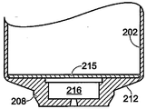
도 3은, 감소된 부피를 점유하도록 또한 구성된 펌프 조립체(100)의 다른 실시예를 도시한다. 펌프 조립체(100)는 드라이버(102) 및 펌프 헤드(104)를 포함한다. 펌프 헤드(104)는 유입구 포트(106), 배출구 포트(108), 피구동 기어(110), 구동 기어(111), 구동 기어(111)가 축방향으로 부착되는 샤프트(112), 피구동 자석(114), 및 자석 컵(116)을 포함한다. 자석 컵(116)은 측벽(116a) 및 말단-단부 벽(116b)을 구비하고, 측벽 및 상기 말단-단부 벽은 피구동 자석(114)과 동축적으로 피구동 자석을 둘러싼다. 말단-단부 벽(116b)에는 센서 변환기(118)가 장착된다. 센서 변환기의 매개변수-감응형 표면이 자석 컵 내에서 일반적으로 펌핑되는 유체에 의해서 습윤되지 않는 상태로 피구동 자석(114)과 대면하도록, 센서 변환기(118)가 장착된다. 센서 변환기(118)의 다른 부분들은 자석 컵으로부터 제 1 인쇄 회로 기판(120)까지 연장된다. 자석 컵의 측벽(116a)을 가로질러 피구동 자석(114)에 자기적으로 커플링되는 스테이터(122)가 자석 컵(116)을 동축적으로 둘러싼다. 스테이터(122)는 외장(124) 내에 위치되고, 그러한 외장은 또한 제 1 인쇄 회로 기판(120)을 수용하며, 상기 제 1 인쇄 회로 기판에는 센서 변환기(118)가 장착된다. 제 1 인쇄 회로 기판(120)은 전도성 핀들(121)에 의해서 제 2 인쇄 회로 기판(126)에 연결된다. 제 1 인쇄 회로 기판(120)은 센서 변환기(118)로부터 변환기 신호들을 수신하고 컨디셔닝하는 전자장치들을 포함하고, 그리고 제 2 인쇄 회로 기판(126)은 스테이터(122)를 위한 드라이버 전자장치들을 포함한다. 이러한 실시예에서, 펌프 헤드(104)는 외장(124)의 벽 내로 적어도 부분적으로 연장하고, 이는 펌프 조립체(100)에 의해서 점유되는 상대적인 부피를 감소시킨다. Figure 3 illustrates another embodiment of a pump assembly 100 configured to also occupy a reduced volume. The pump assembly 100 includes a
자석 컵(116)은 자기적이 아닌 여러 가지 강성(rigid) 재료들 중 임의 재료로 제조될 수 있다. 예를 들어, 자석 컵(116)은 비-자성 금속 또는 금속 합금으로 제조될 수 있으며, 그러한 경우에 자석 컵은 가공, 딥-드로잉(deep-drawing), 또는 주조 등에 의해서 형성될 수 있다. 다른 예로서, 자석 컵은, 예를 들어, 가공 또는 몰딩에 의해서 형성된 폴리머계 또는 코폴리머계 재료로 제조될 수 있다. 폴리머계 또는 코폴리머계 재료는 섬유들, 입자들, 또는 다른 적합한 비-자성 재료를 이용하여 보강될 수 있을 것이다. 비-습윤형 센서가, 자석 컵의 벽을 가로질러, 펌핑되는 유체의 광학적 성질들 또는 그러한 성질들의 변화를 검출할 수 있게 하기 위해서, 폴리머계 자석 컵은 전자석 복사선의 선택된 파장에 대해서 투명하거나 또는 반투명할(translucent) 수 있을 것이다. The
금속으로 제조된 자석 컵(150)의 예시적인 실시예가 도 4에 도시되어 있으며, 도 4에 도시된 컵은 원통형 본체(152)를 포함한다. 상기 본체(152)는 컵을 펌프 헤드에 장착하기 위한 기저부(proximal) 장착 플랜지(154)를 포함한다(도 3 참조). 또한, 상기 본체(152)는 말단-단부 플레이트(156)를 포함하고, 상기 말단-단부 플레이트에는 센서 변환기(158)가 접합되며, 그에 따라 변환기의 매개변수-감응형 표면이 자석 컵의 내부와 대면한다. 핀들(160)에 의해서 환형 회로 기판(162)에 연결된 센서 변환기(158)의 대향(외측을 대면하는) 표면을 도면에서 볼 수 있다. 회로 기판(162)은 수형 커넥터 핀들(164)을 포함하며, 회로 기판(162)은 별개의 회로 기판(도시하지 않음) 상에 위치된 다른 전자장치에 수형 커넥터 핀들(164)에 의해 전기적으로 연결된다. 도 5에서 다른 사시도로 또한 도시된 도 4의 자석 컵(150)은 도 1에 도시된 자석 컵(26) 및 도 3에 도시된 자석 컵(116)과 유사하다. 도 5에 도시된 절개 라인들을 따른 단면도는, 도 6에 도시된 바와 같이, 일부 부가적인 구체적인 사항들 예를 들어 목적들을 제공한다. 원통형 본체(152), 자석 컵(150)의 말단-단부 플레이트(156), 센서 변환기(158), 인쇄 회로 기판(162), 및 연결 핀들(164)이 도 6에 도시되어 있다. 핀들(164)이 커버(166)를 통해서 연장하는 상태로, 회로 기판(162)과 센서 변환기(158) 위에 피팅되도록 구성된 커버(166)가 도 6에 도시되어 있다. 도 4에 도시된 컵(150)은 도 6의 컵과 유사하나, 도 6에 도시된 커버(166)를 포함하고 있지 않다. 유사하게, 도 1에 도시된 컵(26)은 커버를 포함하는 한편, 도 3에 도시된 컵(116)은 커버를 포함하지 않는다. An exemplary embodiment of a
도 6의 실시예에서, 센서 변환기(158)는 말단-단부 플레이트(156)로 밀봉식으로 통합되고, 그에 따라 센서 변환기(158)는 환형 인쇄 회로 기판(162)과 접촉되어 유지되고 그리고 환형 인쇄 회로 기판(162)에 의해서 둘러싸인다. 이는, 독립적인 연결 와이어들 및 연관된 관통-홀들을 필요로 하지 않고, 센서 변환기(158)로부터의 전기 신호들이 핀들(160)(도 4 참조)을 통해서 회로 기판(162) 상의 하드웨어 요소들에 대해서 직접적으로 연결될 수 있게 허용한다. 센서 변환기(158)는 얇은 플레이트(156)의 건성 측부(side)와 통합되고, 상기 플레이트는 습성 환경과 건성 환경 사이의 배리어를 형성하는 한편, 센서 변환기(158)가 관심 대상이 되는 하나 또는 둘 이상의 유체적 매개변수들을 검출할 수 있게 한다. 센서 변환기(158)를 습성 표면에 근접하여 배치하는 것은 펌핑되는 유체와 직접적으로 접촉하는 것을 방지하고, 그에 따라 센서 변환기(158)가 "비-습윤형" 센서로서 동작하게 된다. 센서 변환기(158)를 플레이트(156)와 통합하는 것, 그리고 센서 변환기를 회로 기판(162)에 직접적으로 연결하는 것은 기계적으로 강성인 유닛을 형성하고, 그러한 유닛은 센서 데이터의 신뢰가능한 전송을 위한 전기적 연속성의 무결성(integrity)을 보장하기가 더 쉽다. 6, the
도 7은 커버(166)를 포함하는 자석 컵(150)의 다른 사시도이다. 자석 컵(150) 및 피구동 자석(114)의 단면이 도 8에 도시되어 있다. 도 9는 자석 컵(150)의 내부를 압력-순응형으로 만들기 위해서 이용되는 특징부들을 도시하는 자석 컵(150)의 분해도이다. 2008년 8월 29일자로 출원되고 본원에서 참조에 의해서 포함되는 미국 특허출원 제 US 2009-0060728 호, 특히 도 1e, 2, 3, 4a, 4b 및 5에 도시된 그리고 그 특허출원의 문단 42-48 및 53-60에 기술된 압력-흡수 부재들의 실시예들을 참조한다. 이러한 특징부들은 플러그(168)(플루오실리콘 포옴(foam)으로 제조됨) 및 유지부(retainer; 170)를 포함한다. 또한 피구동 자석(172) 및 유지부 슈(174)가 도시되어 있다.FIG. 7 is another perspective view of a
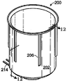
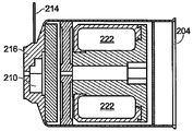
몰딩된 강성 폴리머 재료로 제조된 자석 컵(200)의 예시적인 실시예가 도 10에 도시되어 있으며, 여기에서 도시된 컵은 원통형 본체(202)를 포함한다. 본체(202)는 컵을 펌프 헤드(도시하지 않음)에 장착하기 위한 기저부 장착 플랜지(204)를 포함한다. 또한, 본체(202)는 또한 강경화(stiffening) 리브들(ribs; 206) 및 말단-단부 벽(208)을 포함하고, 변환기의 매개변수-감응형 표면이 자석 컵의 내부와 대면하도록 센서 변환기(210)가 상기 말단-단부 벽에 접합된다. 말단-단부 벽(208)은 또한 강경화 리브들(212)을 포함한다. 센서 변환기(210)는 핀들(214)을 포함하고, 그러한 핀들에 의해서 센서 변환기가 회로 기판(도시하지 않음)에 전기적으로 연결된다. 이 이외에, 도 10의 자석 컵(200)은 도 2에 도시된 자석 컵(66)과 유사하다. An exemplary embodiment of a
자석 컵(200)의 구체적인 사항들이 도 11 및 12에 도시되어 있으며, 여기에서 본체(202)의 부분이 말단-단부 벽(208)과 함께 도시되어 있다. 말단-단부 벽(208)은 공동(216)을 형성하며, 그러한 공동 내에서 센서 변환기(210)가 (예를 들어, 접착제의 이용에 의해서) 밀봉식으로 장착되고, 그에 따라 센서 변환기(210)가 비-습윤형 센서로서 동작된다. 도 13은 자석 컵(200)의 다른 사시도를 도시하고, 그리고 자석 컵(200)의 단면이 도 14에 도시되어 있다. 자석 컵(200)의 내부를 압력-순응형으로 만들기 위해서 이용되는 특정의 특징부들(features)을 포함하여, 추가적인 구체적인 사항들을 도 15에 도시하였다. 그러한 특징부들에는 (예를 들어, 플루오로실리콘 포옴으로 제조된) 플러그(218) 및 유지부(220)가 포함된다. 또한, 피구동 자석(222) 및 유지부 슈(224)가 도시되어 있다. Specific details of the
도 16은 자기 컵(230)의 다른 실시예를 도시하며, 그러한 자기 컵(230)은 측벽(232), 말단-단부 벽(234), 기저부 장착 플랜지(236), 및 하나 또는 둘 이상의 비-습윤형 센서들(240)의 조립체(238)를 포함한다. 이러한 실시예에서, 센서 조립체(238)는 말단-단부 벽(234) 내로 통합되는 대신에 측벽(232)으로 통합된다. 개별적인 센서들(240)이 자기 컵(230)의 원주방향 둘레의 링 내에 배치될 수 있을 것이고, 그에 따라 그 센서들이 컵(230)의 표면 위로 돌출할 수 있을 것이다. 그 대신에, 센서들(240)이 본체(232)의 표면 상에 또는 그 표면 내에 배치된 미니- 또는 마이크로-기계적 센서들로서 구성될 수 있을 것이다. 센서 조립체(238)는 도시된 바와 같은 좁은 링, 넓은 링, 또는 측벽(232)과 동축적인 외측 실린더로서 구성될 수 있을 것이다. 16 illustrates another embodiment of a
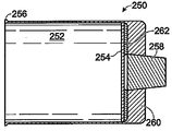
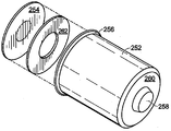
도 17 및 18은 자기 컵(250)의 다른 실시예를 도시하고, 그러한 자기 컵(250)은 측벽(252), 상기 측벽(252) 보다 더 두꺼울 수 있는 말단-단부 벽(254), 기저부 장착 플랜지(256), 및 비-습윤형 센서(258)를 포함한다. 이러한 실시예에서, 센서(258)가 말단-단부 벽(254) 내로 삽입될 수 있고 그리고 커버(260) 및 밀봉부(262)에 의해서 제위치에서 유지된다. 밀봉부(262)가 접착제, 가스켓, 또는 o-링 등일 수 있을 것이다. 17 and 18 illustrate another embodiment of a
도 19는 전술한 바와 같은 하나 또는 둘 이상의 감지 요소를 포함하는 자가-변조(self-modulating) 펌프 조립체를 위한 예시적인 피드백 제어 시스템(300)을 도시한다. 예를 들어, 피드백 제어 시스템(300)은 펌프 조립체와 관련하여 규정된(prescribed) 온도 또는 압력을 유지하기 위해서 이용될 수 있을 것이다. 전술한 바와 같이, 부가적인 하우징들, 배선들, 또는 밀봉부들이 없이도, 제어 시스템의 모든 요소들이 펌프 조립체 내에 위치될 수 있다. 소프트웨어 부분(302) 및 하드웨어 부분(304)이 각각 도시되어 있다. 예시적인 소프트웨어 부분(302)은 피드백-제어 시스템들에서 전형적으로 이용되는 적분(integral) 제어기(306) 및 비례 제어기(308)를 포함한다. 예시적인 하드웨어 부분(304)은 디지털-대-아날로그 변환기(DAC)(310), 아날로그-대-디지털 변환기(ADC)(312), 모터 스테이터(BLDC 모터)(316)를 구동하기 위한 모터 제어기(BLDC)(314), 그에 따라 펌프(318) 및 적어도 하나의 감지 요소(320)를 포함한다. FIG. 19 illustrates an exemplary feedback control system 300 for a self-modulating pump assembly including one or more sensing elements as described above. For example, the feedback control system 300 may be utilized to maintain a prescribed temperature or pressure with respect to the pump assembly. As described above, without the need for additional housings, wires, or seals, all elements of the control system can be located within the pump assembly.
감지 요소(320)에 의해서 획득된 측정에 기초하여 펌프(318)에 대한 피드백 제어를 제공하기 위해서, 감지 요소(320)로부터의 측정된 피드백 신호(322)가 ADC(312)에 의해서 제 1 디지털 피드백 신호(324)로 변환되고, 그러한 제 1 디지털 피드백 신호는 소프트웨어 부분(302)에 의해서 프로세싱될 수 있다. 부가적인 데이터가 제 2 디지털 피드백 신호(326)에 의해서 외부 공급원으로부터의 제 1 디지털 피드백 신호(324)와 조합될 수 있을 것이다. 제어기들(306, 308)에 의한 프로세싱을 위해서, 제 1 다중화기(multiplexer)(328)가 디지털 피드백 신호들(324, 326)을 조합한다. 이어서, 비례 제어 신호(330) 및 적분 제어 신호(332)가 제 2 다중화기(334)에 의해서 조합되어 복합 제어 신호(336)를 형성할 수 있을 것이다. 이어서, 복합 제어 신호(336)는 아날로그 제어 신호(338)로의 변환을 위해서 DAC(310)로 전송될 수 있을 것이다. 아날로그 제어 신호(338)는 BLDC 제어기(314)에 의해서 프로세싱될 수 있을 것이고, 그리고 후속하여 펌프(318)의 성능을 제어하기 위해서 모터(316)로 적절한 시간에 전달될 수 있을 것이다. The measured feedback signal 322 from the
개시된 본원 발명의 원리들이 적용될 수 있는 많은 가능한 실시예들에 비추어 볼 때, 도시된 실시예들이 단지 본원 발명의 바람직한 예들이라는 것 그리고 본원 발명의 범위를 제한하는 것으로 받아들이지 않아야 한다는 것을 이해하여야 할 것이다. 그 대신에, 본원 발명의 범위는 이하의 청구항들에 의해서 규정된다. 그에 따라, 이러한 청구항들의 범위 및 사상으로부터 유래되는 모든 것들을 본원 발명으로 청구한다. It is to be understood that the illustrated embodiments are merely preferred embodiments of the invention and should not be construed as limiting the scope of the invention in light of the many possible embodiments to which the principles of the invention disclosed may be applied. Instead, the scope of the present invention is defined by the following claims. Accordingly, all that comes within the scope and spirit of these claims is claimed as the invention.
50 : 펌프 조립체 52 : 드라이버
54 : 펌프 헤드 56 : 유입구 포트
58 : 배출구 포트 60 : 구동 기어
61 : 피구동 기어 62 : 샤프트
64 : 피구동 자석 66 : 자석 컵
66a : 측벽 66b : 말단-단부 벽
68 : 센서 변환기 70 : 인쇄 회로 기판
72 : 스테이터 74 : 외장 50: Pump assembly 52: Driver
54: Pump head 56: Inlet port
58: Exhaust port 60: Drive gear
61: driven gear 62: shaft
64: driven magnet 66: magnetic cup
66a:
68: sensor converter 70: printed circuit board
72: stator 74: sheath
Claims (27)
밀봉된 펌프 하우징을 포함하는 펌프 헤드와,
상기 펌프 하우징 내부에 위치되는 이동가능한 펌핑 부재와,
피구동 자석의 유도된 운동이 상기 펌핑 부재의 대응하는 유도된 운동을 유발하도록 상기 펌핑 부재에 연결되는 피구동 자석과,
상기 피구동 자석의 유도된 운동이 자석 하우징 내에서 발생되도록 피구동 자석을 수용하고 그리고 상기 펌프 하우징의 개별적인 부분인 자석 하우징으로서, 상기 피구동 자석 및 상기 자석 하우징의 내부가 펌핑 부재의 유도된 운동에 의해 펌핑되는 유체에 의해 습윤되는, 자석 하우징과,
적어도 하나의 센서 요소로서, 센서 요소가 유체에 의해 습윤되지 않도록 상기 자석 하우징의 벽에 대해 밀봉식으로 장착되는, 적어도 하나의 센서 요소와,
자석-드라이버에 의해 생성되는 자기장의 변화가 상기 피구동 자석의 운동을 유도하여 상기 하우징 내의 펌핑 부재의 운동을 유도하도록, 상기 자석 하우징 외부에 위치되고 그리고 피구동 자석에 자기적으로 커플링되는, 자석-드라이버를 포함하는,
펌프 조립체. Pump assembly,
A pump head including a sealed pump housing,
A movable pumping member positioned within the pump housing,
A driven magnet connected to the pumping member such that an induced movement of the driven magnet causes a corresponding induced movement of the pumping member;
A magnet housing that receives the driven magnet and is an individual part of the pump housing such that an induced movement of the driven magnet is generated in the magnet housing, the interior of the driven magnet and the magnet housing being driven by an induced movement of the pumping member The magnet housing being wetted by a fluid pumped by the magnet housing;
At least one sensor element, said sensor element being sealingly mounted against a wall of the magnet housing such that the sensor element is not wetted by the fluid,
Wherein a change in the magnetic field produced by the magnet-driver is located outside the magnet housing and is magnetically coupled to the driven magnet to induce movement of the driven magnet to induce movement of the pumping member within the housing. Including a magnet-driver,
Pump assembly.
상기 습성 표면은 상기 자석 하우징의 내부에서 유체와 접촉하며,
상기 센서 요소는 상기 자석 하우징의 내부에서 유체와 접촉하지 않는, 펌프 조립체.2. The method of claim 1, wherein the wall of the magnet housing comprises a wetting surface and a dry surface,
Wherein the wetted surface is in fluid contact with the interior of the magnet housing,
Wherein the sensor element is not in fluid contact with the interior of the magnet housing.
상기 구동 기어는 상기 피구동 자석에 커플링되는, 펌프 조립체.2. The apparatus according to claim 1, wherein the pumping member includes a driven gear engaged with the driving gear and the driving gear,
And the drive gear is coupled to the driven magnet.
상기 센서 요소는 상기 말단-단부 벽 내에 일체화되며,
상기 센서 요소는, 상기 센서 요소에 대한 강성 전기 연결부를 포함하는, 회로 기판에 의해 둘러싸이는, 펌프 조립체.2. The magnet housing of claim 1, wherein the magnet housing comprises a body and an end-
The sensor element is integrated within the end-end wall,
Wherein the sensor element comprises a rigid electrical connection to the sensor element.
상기 모터 하우징 내에 위치되고 그리고 상기 스테이터에 전기적으로 연결되는 스테이터-드라이버 전자장치를 더 포함하는, 펌프 조립체.13. The stator of claim 12, further comprising: a motor housing for housing the stator;
And a stator-driver electronics device located within the motor housing and electrically connected to the stator.
상기 센서 요소는 유입구 압력을 감지하기 위해 상기 자석 하우징의 펌프-유입구 영역에 위치되거나, 배출구 압력을 감지하기 위해 상기 자석 하우징의 펌프-배출구 영역에 위치되는, 펌프 조립체.2. The apparatus of claim 1, wherein the sensor element is a pressure transducer,
Wherein the sensor element is located in a pump-inlet region of the magnet housing to sense inlet pressure or in a pump-outlet region of the magnet housing to sense outlet pressure.
상기 펌프 하우징 외부에 위치되고 그리고 상기 자석 드라이버에 전기적으로 연결되는 드라이버 회로와,
상기 센서 전자 회로 및 상기 드라이버 회로에 전기적으로 연결되는 제어기를 더 포함하며,
상기 제어기는, 상기 센서 전자 회로에 의해 상기 제어기로 제공되는 데이터에 기초하여, 상기 자석 드라이버의 동작을 제어하여 상기 펌핑 부재의 동작을 제어하도록 구성되는, 펌프 조립체.2. The sensor assembly of claim 1, further comprising: sensor electronics located outside the pump housing and electrically connected to the sensor element;
A driver circuit located outside the pump housing and electrically connected to the magnet driver,
And a controller electrically connected to the sensor electronics and the driver circuit,
Wherein the controller is configured to control operation of the pumping member by controlling operation of the magnet driver based on data provided by the sensor electronics to the controller.
밀봉된 펌프 하우징과,
상기 하우징 내부에 위치되는 펌핑 부재와,
피구동 자석의 유도된 운동이 상기 펌핑 부재의 대응하는 유도된 운동을 유발하도록, 상기 펌핑 부재에 연결되고 그리고 상기 하우징 내에 위치되는, 피구동 자석과,
상기 피구동 자석의 유도된 운동이 자석 하우징 내에서 발생되도록 피구동 자석을 수용하고 그리고 상기 펌프 하우징의 개별적인 부분인 자석 하우징으로서, 상기 피구동 자석 및 상기 자석 하우징의 내부가 펌핑 부재의 유도된 운동에 의해 펌핑되는 유체에 의해 습윤되는, 자석 하우징과,
적어도 하나의 센서 요소로서, 센서 요소가 상기 펌핑 부재에 의해 펌핑되는 유체의 적어도 하나의 매개변수에 대해 감응하도록, 상기 자석 하우징의 벽에 일체로 장착되는, 적어도 하나의 센서 요소를 포함하는,
펌프 헤드. Pump head,
A sealed pump housing,
A pumping member positioned within the housing,
A driven magnet connected to the pumping member and positioned within the housing such that an induced movement of the driven magnet induces a corresponding induced movement of the pumping member;
A magnet housing that receives the driven magnet and is an individual part of the pump housing such that an induced movement of the driven magnet is generated in the magnet housing, the interior of the driven magnet and the magnet housing being driven by an induced movement of the pumping member The magnet housing being wetted by a fluid pumped by the magnet housing;
At least one sensor element, wherein at least one sensor element is integrally mounted on a wall of the magnet housing such that the sensor element is sensitive to at least one parameter of fluid pumped by the pumping member.
Pump head.
상기 센서 요소는 상기 매개변수-감응형 표면이 자석 컵의 내부를 향하도록 상기 자석 하우징의 벽에 일체로 장착되는, 펌프 헤드.24. The system of claim 23, wherein the sensor element comprises a parameter-responsive surface capable of measuring the nature of the fluid being pumped,
Wherein the sensor element is mounted integrally with a wall of the magnet housing such that the parameter-sensitive surface faces the interior of the magnet cup.
센서가 유체에 의해 습윤되지 않도록 상기 자석 하우징의 벽에 대해 장착되는 센서를 제공하는 단계와,
유체의 적어도 하나의 매개변수를 측정하여 측정 신호를 생성하기 위해 상기 센서를 이용하는 단계와,
상기 측정 신호를 제어 신호로서 상기 전자 구성요소에 공급하는 단계로서, 상기 제어 신호는 상기 매개변수의 측정에 기초하는 적어도 하나의 특성을 갖고 그리고 상기 전자 구성요소가 동작적으로 응답하는 신호인, 측정 신호 공급 단계와,
상기 제어 신호에 기초하여 상기 펌프의 구동을 대응하게 변화시키도록 상기 전자 구성요소를 유도하는 단계를 포함하는,
자기적으로-구동되는 유압식 펌프를 제어하기 위한 방법. A method for controlling a magnetically-driven hydraulic pump in which pumped fluid is separated from a pump-driven electronic component by a pump housing comprising a magnet housing,
Providing a sensor mounted against a wall of the magnet housing such that the sensor is not wetted by the fluid,
Using the sensor to measure at least one parameter of the fluid to generate a measurement signal,
Supplying said measurement signal as a control signal to said electronic component, wherein said control signal has at least one characteristic based on a measurement of said parameter and wherein said electronic component is a signal operatively responding, A signal supply step,
And deriving the electronic component to correspondingly change the drive of the pump based on the control signal.
A method for controlling a magnetically-driven hydraulic pump.
피구동 자석 수단에 자기적으로 커플링된 펌프-요소 수단과,
상기 펌프-요소 수단을 외부 환경으로부터 분리되게 그리고 펌핑되는 유체와 접촉하게 수용하기 위한 펌프 하우징 수단으로서, 상기 피구동 자석 수단을 위한 하우징 수단을 포함하는, 펌프 하우징 수단과,
상기 피구동 자석 수단의 운동을 유도하여 상기 하우징 수단 내에서 상기 펌프-요소 수단의 운동을 유도하기 위해 상기 피구동 자석 수단을 위한 하우징 수단의 외부에 위치되는 자석-구동 수단과,
유체와의 접촉 없이 유체의 적어도 하나의 성질을 측정하기 위해 상기 하우징 수단과 연관되는 매개변수 감지 수단과,
상기 측정된 적어도 하나의 성질과 연관된 데이터를 수신하고 그리고 대응하는 펌프-제어 신호를 생성하기 위해 상기 매개변수 감지 수단에 커플링되는 펌프 제어 수단과,
상기 대응하는 펌프-제어 신호에 응답하여 상기 펌프의 동작을 조절하기 위한 수단을 포함하는,
유체 펌프. A fluid pump,
Pump-element means magnetically coupled to the driven magnet means,
Pump housing means for housing the pump-element means in isolation from the external environment and in contact with a fluid to be pumped, the pump housing means including housing means for the driven magnet means;
Magnet-drive means located outside of the housing means for said driven magnet means for inducing movement of said driven magnet means to induce movement of said pump-element means in said housing means;
A parameter sensing means associated with the housing means for measuring at least one property of the fluid without contact with the fluid,
Pump control means coupled to said parameter sensing means for receiving data associated with said measured at least one property and for generating a corresponding pump-control signal,
And means for adjusting the operation of the pump in response to the corresponding pump-control signal.
Fluid pump.
Applications Claiming Priority (5)
| Application Number | Priority Date | Filing Date | Title |
|---|---|---|---|
| US39671510P | 2010-06-01 | 2010-06-01 | |
| US61/396,715 | 2010-06-01 | ||
| US13/151,188 US20110293450A1 (en) | 2010-06-01 | 2011-06-01 | Pump magnet housing with integrated sensor element |
| US13/151,188 | 2011-06-01 | ||
| PCT/US2011/038952 WO2011153367A1 (en) | 2010-06-01 | 2011-06-02 | Pump magnet housing with integrated sensor element |
Publications (1)
| Publication Number | Publication Date |
|---|---|
| KR20140074789A true KR20140074789A (en) | 2014-06-18 |
Family
ID=45022294
Family Applications (1)
| Application Number | Title | Priority Date | Filing Date |
|---|---|---|---|
| KR1020127033978A KR20140074789A (en) | 2010-06-01 | 2011-06-02 | Pump magnet housing with integrated sensor element |
Country Status (7)
| Country | Link |
|---|---|
| US (1) | US20110293450A1 (en) |
| EP (1) | EP2417353A4 (en) |
| JP (1) | JP2013530669A (en) |
| KR (1) | KR20140074789A (en) |
| BR (1) | BR112012030665A2 (en) |
| CA (1) | CA2801495A1 (en) |
| WO (1) | WO2011153367A1 (en) |
Families Citing this family (29)
| Publication number | Priority date | Publication date | Assignee | Title |
|---|---|---|---|---|
| DE10224750A1 (en) | 2002-06-04 | 2003-12-24 | Fresenius Medical Care De Gmbh | Device for the treatment of a medical fluid |
| US8197231B2 (en) | 2005-07-13 | 2012-06-12 | Purity Solutions Llc | Diaphragm pump and related methods |
| US8192401B2 (en) | 2009-03-20 | 2012-06-05 | Fresenius Medical Care Holdings, Inc. | Medical fluid pump systems and related components and methods |
| EP2453946B1 (en) | 2009-07-15 | 2013-02-13 | Fresenius Medical Care Holdings, Inc. | Medical fluid cassettes and related systems |
| US9624915B2 (en) | 2011-03-09 | 2017-04-18 | Fresenius Medical Care Holdings, Inc. | Medical fluid delivery sets and related systems and methods |
| EP3006059B1 (en) | 2011-04-21 | 2017-09-27 | Fresenius Medical Care Holdings, Inc. | Medical fluid pumping systems and related devices and methods |
| EP2773872B1 (en) * | 2011-10-31 | 2019-03-06 | M Pumps Srl | Device for transmitting power through rotating magnetic fields |
| CN104105877B (en) * | 2011-12-07 | 2017-09-22 | 流量控制有限责任公司 | Use the pump with idle running and the multivoltage electronic device of overcurrent protection |
| US9610392B2 (en) | 2012-06-08 | 2017-04-04 | Fresenius Medical Care Holdings, Inc. | Medical fluid cassettes and related systems and methods |
| US9500188B2 (en) * | 2012-06-11 | 2016-11-22 | Fresenius Medical Care Holdings, Inc. | Medical fluid cassettes and related systems and methods |
| US9130413B2 (en) | 2012-07-25 | 2015-09-08 | Nidec Motor Corporation | Electric motor having a partially sealed housing |
| DE102012218012A1 (en) * | 2012-10-02 | 2014-04-03 | Alfmeier Präzision AG Baugruppen und Systemlösungen | Housing with two plastic housing parts |
| US20140161651A1 (en) * | 2012-12-11 | 2014-06-12 | Micropump, Inc, a Unit of IDEX Corporation | Compact integrated-drive pumps |
| US9561323B2 (en) | 2013-03-14 | 2017-02-07 | Fresenius Medical Care Holdings, Inc. | Medical fluid cassette leak detection methods and devices |
| WO2014145018A2 (en) * | 2013-03-15 | 2014-09-18 | Levant Power Corporation | Active vehicle suspension improvements |
| WO2014179394A1 (en) * | 2013-05-01 | 2014-11-06 | Flow Control Llc. | Pump using multi voltage electronics with run dry and over current protection |
| DE102013018159A1 (en) * | 2013-12-05 | 2015-06-11 | Klaus Union Gmbh & Co. Kg | Slit pot and method for producing the same |
| JP5943955B2 (en) * | 2014-04-07 | 2016-07-05 | 三菱電機株式会社 | Range switching device |
| CN105526160A (en) * | 2014-10-16 | 2016-04-27 | 德昌电机(深圳)有限公司 | Gear pump |
| USD861733S1 (en) * | 2016-04-11 | 2019-10-01 | Robert Bosch Gmbh | Hydraulic power unit |
| US20190271309A1 (en) * | 2016-07-27 | 2019-09-05 | Nidec Tosok Corporation | Electric pump |
| DE102016114540A1 (en) * | 2016-08-05 | 2018-02-08 | Eckerle Industrie-Elektronik Gmbh | Electrohydraulic machine with integrated sensor |
| US10660997B2 (en) * | 2016-09-23 | 2020-05-26 | Heartware, Inc. | Blood pump with sensors on housing surface |
| EP3415733A1 (en) * | 2017-06-14 | 2018-12-19 | MEAS France | Fluid quality sensor for measuring the quality of a fluid, sensor assembly and assembly for combustion engines comprising a fluid quality sensor |
| CN109385642B (en) * | 2017-08-04 | 2021-04-13 | 林信涌 | Gas generator |
| FR3074544B1 (en) * | 2017-12-05 | 2021-10-22 | Ams R&D Sas | PILOT WAVING DIAPHRAGM CIRCULATOR |
| FR3078115B1 (en) * | 2018-02-22 | 2021-08-06 | Wilo Intec | FLUID CIRCULATION PUMP WITH NON-INTRUSIVE PRESSURE MEASUREMENT |
| EP4008908A1 (en) * | 2020-12-02 | 2022-06-08 | Zi Yi Electrical Engineering Co., Ltd. | Canned motor pump with leak sensor |
| WO2023084021A1 (en) | 2021-11-12 | 2023-05-19 | Grundfos Holding A/S | Temperature sensor device for measuring a temperature of a liquid flowing through a pump |
Family Cites Families (15)
| Publication number | Priority date | Publication date | Assignee | Title |
|---|---|---|---|---|
| US4387313A (en) * | 1981-04-22 | 1983-06-07 | Mitsubishi Denki Kabushiki Kaisha | Molded submersible motor |
| US5096390A (en) * | 1990-10-16 | 1992-03-17 | Micropump Corporation | Pump assembly with integral electronically commutated drive system |
| US5181837A (en) * | 1991-04-18 | 1993-01-26 | Vickers, Incorporated | Electric motor driven inline hydraulic apparatus |
| DE69526717T2 (en) * | 1995-01-11 | 2003-01-30 | Micropump Inc | System with built-in pump and fluid flow meter |
| US5961293A (en) * | 1995-05-19 | 1999-10-05 | Uis, Inc | In-take fuel pump assembly with unitary control unit for internal combustion engines |
| JP4493061B2 (en) * | 1999-04-22 | 2010-06-30 | 油研工業株式会社 | Hydraulic pump with built-in electric motor |
| EP1085210A3 (en) * | 1999-09-13 | 2004-03-31 | Siemens Aktiengesellschaft | Pump with temperature sensor on the housing |
| AUPR806801A0 (en) * | 2001-10-03 | 2001-10-25 | Davey Products Pty Ltd | Pump control system |
| US7001158B2 (en) * | 2003-01-24 | 2006-02-21 | Sturman Industries, Inc. | Digital fluid pump |
| EP1884010B1 (en) * | 2005-05-17 | 2014-04-30 | Carter Fuel Systems, LLC | Bldc motor and pump assembly with encapsulated circuit board |
| US8591198B2 (en) * | 2007-05-22 | 2013-11-26 | Metropolitan Industries, Inc. | Strain gauge pump control switch |
| US8323008B2 (en) * | 2007-08-30 | 2012-12-04 | Micropump, Inc., A Unit Of Idex Corporation | Pumps and pump-heads comprising internal pressure-absorbing member |
| US7654804B2 (en) * | 2008-01-08 | 2010-02-02 | Chu Henry C | Fluid displacement apparatus having pressure sensing device |
| US7789049B2 (en) * | 2008-07-14 | 2010-09-07 | Honda Motor Co., Ltd. | Variable capacity water pump via electromagnetic control |
| FR2936844A1 (en) * | 2008-10-02 | 2010-04-09 | Inergy Automotive Systems Res | ROTARY PUMP FOR VEHICLE |
-
2011
- 2011-06-01 US US13/151,188 patent/US20110293450A1/en not_active Abandoned
- 2011-06-02 JP JP2013513351A patent/JP2013530669A/en not_active Withdrawn
- 2011-06-02 CA CA2801495A patent/CA2801495A1/en not_active Abandoned
- 2011-06-02 KR KR1020127033978A patent/KR20140074789A/en not_active Application Discontinuation
- 2011-06-02 BR BR112012030665A patent/BR112012030665A2/en not_active IP Right Cessation
- 2011-06-02 EP EP11735965.3A patent/EP2417353A4/en not_active Withdrawn
- 2011-06-02 WO PCT/US2011/038952 patent/WO2011153367A1/en active Application Filing
Also Published As
| Publication number | Publication date |
|---|---|
| US20110293450A1 (en) | 2011-12-01 |
| BR112012030665A2 (en) | 2017-06-13 |
| EP2417353A1 (en) | 2012-02-15 |
| WO2011153367A1 (en) | 2011-12-08 |
| EP2417353A4 (en) | 2013-10-09 |
| CA2801495A1 (en) | 2011-12-08 |
| JP2013530669A (en) | 2013-07-25 |
Similar Documents
| Publication | Publication Date | Title |
|---|---|---|
| KR20140074789A (en) | Pump magnet housing with integrated sensor element | |
| EP2474820B1 (en) | Pressure sensor with low cost packaging | |
| US5438876A (en) | Modular diaphragm pressure sensor with peripheral mounted electrical terminals | |
| US7430918B2 (en) | Amplified flow through pressure sensor | |
| JP2013530669A5 (en) | ||
| KR101898758B1 (en) | Device for transmitting power through rotating magnetic fields | |
| JP2001527210A (en) | Universal media package for pressure sensing devices | |
| AU2018214815B2 (en) | Improved pressure transducer | |
| EP2002233A2 (en) | High temperature pressure transmitter assembly | |
| EP3538857A2 (en) | Pressure sensor sub assembly and fabrication | |
| US5975842A (en) | Sensor arrangement | |
| JPH07294358A (en) | Pressure-sensing device and its manufacture | |
| CN107192498A (en) | Elongated pressure sensor full of fluid | |
| JP6830175B2 (en) | Pressure sensor assemblies, measuring instruments, and how to make them | |
| EP0769266B1 (en) | Blood pressure measuring module | |
| JP6830174B2 (en) | Pressure sensor assemblies, measuring instruments, and how to make them | |
| CN103959017A (en) | Sensor module with a displacement sensor and a pressure sensor in a common housing | |
| US10620071B2 (en) | Pressure sensor and method for manufacturing a pressure sensor | |
| EP3759451B1 (en) | Pressure sensor | |
| JP6872475B2 (en) | Multi-axis actuator with integrated load sensor and load sensor | |
| US20230175501A1 (en) | Integrated electrically submersible pump sensor device | |
| JP5415033B2 (en) | Fluid circulation device | |
| WO2002073775A1 (en) | Improvements in electric motor driven hydraulic pumps | |
| CN117232695A (en) | Preformed solid as coupling mechanism in media isolated pressure sensor | |
| US20170038271A1 (en) | Universal hermetically sealed button pressure sensor |
Legal Events
| Date | Code | Title | Description |
|---|---|---|---|
| WITN | Application deemed withdrawn, e.g. because no request for examination was filed or no examination fee was paid |