KR20140070032A - Improved secondary battery assembly for connection structure of electrode, secondary battery for the same and fabrication method thereof - Google Patents
Improved secondary battery assembly for connection structure of electrode, secondary battery for the same and fabrication method thereof Download PDFInfo
- Publication number
- KR20140070032A KR20140070032A KR1020120138015A KR20120138015A KR20140070032A KR 20140070032 A KR20140070032 A KR 20140070032A KR 1020120138015 A KR1020120138015 A KR 1020120138015A KR 20120138015 A KR20120138015 A KR 20120138015A KR 20140070032 A KR20140070032 A KR 20140070032A
- Authority
- KR
- South Korea
- Prior art keywords
- electrode
- cell
- cover
- cell cover
- joint portion
- Prior art date
Links
- 238000000034 method Methods 0.000 title claims description 13
- 238000004519 manufacturing process Methods 0.000 title description 7
- 210000004027 cell Anatomy 0.000 claims abstract description 96
- 210000005056 cell body Anatomy 0.000 claims abstract description 41
- 238000003466 welding Methods 0.000 claims description 9
- 239000007769 metal material Substances 0.000 claims description 5
- 238000012986 modification Methods 0.000 description 3
- 230000004048 modification Effects 0.000 description 3
- 238000001816 cooling Methods 0.000 description 1
- 238000005336 cracking Methods 0.000 description 1
- 238000007599 discharging Methods 0.000 description 1
- 239000003792 electrolyte Substances 0.000 description 1
- 230000017525 heat dissipation Effects 0.000 description 1
- 238000009413 insulation Methods 0.000 description 1
- 238000010030 laminating Methods 0.000 description 1
- 238000003860 storage Methods 0.000 description 1
Images


Classifications
-
- H—ELECTRICITY
- H01—ELECTRIC ELEMENTS
- H01M—PROCESSES OR MEANS, e.g. BATTERIES, FOR THE DIRECT CONVERSION OF CHEMICAL ENERGY INTO ELECTRICAL ENERGY
- H01M50/00—Constructional details or processes of manufacture of the non-active parts of electrochemical cells other than fuel cells, e.g. hybrid cells
- H01M50/10—Primary casings; Jackets or wrappings
-
- H—ELECTRICITY
- H01—ELECTRIC ELEMENTS
- H01M—PROCESSES OR MEANS, e.g. BATTERIES, FOR THE DIRECT CONVERSION OF CHEMICAL ENERGY INTO ELECTRICAL ENERGY
- H01M10/00—Secondary cells; Manufacture thereof
- H01M10/04—Construction or manufacture in general
- H01M10/0413—Large-sized flat cells or batteries for motive or stationary systems with plate-like electrodes
-
- H—ELECTRICITY
- H01—ELECTRIC ELEMENTS
- H01M—PROCESSES OR MEANS, e.g. BATTERIES, FOR THE DIRECT CONVERSION OF CHEMICAL ENERGY INTO ELECTRICAL ENERGY
- H01M10/00—Secondary cells; Manufacture thereof
- H01M10/05—Accumulators with non-aqueous electrolyte
- H01M10/058—Construction or manufacture
- H01M10/0585—Construction or manufacture of accumulators having only flat construction elements, i.e. flat positive electrodes, flat negative electrodes and flat separators
-
- H—ELECTRICITY
- H01—ELECTRIC ELEMENTS
- H01M—PROCESSES OR MEANS, e.g. BATTERIES, FOR THE DIRECT CONVERSION OF CHEMICAL ENERGY INTO ELECTRICAL ENERGY
- H01M50/00—Constructional details or processes of manufacture of the non-active parts of electrochemical cells other than fuel cells, e.g. hybrid cells
- H01M50/50—Current conducting connections for cells or batteries
- H01M50/531—Electrode connections inside a battery casing
-
- Y—GENERAL TAGGING OF NEW TECHNOLOGICAL DEVELOPMENTS; GENERAL TAGGING OF CROSS-SECTIONAL TECHNOLOGIES SPANNING OVER SEVERAL SECTIONS OF THE IPC; TECHNICAL SUBJECTS COVERED BY FORMER USPC CROSS-REFERENCE ART COLLECTIONS [XRACs] AND DIGESTS
- Y02—TECHNOLOGIES OR APPLICATIONS FOR MITIGATION OR ADAPTATION AGAINST CLIMATE CHANGE
- Y02E—REDUCTION OF GREENHOUSE GAS [GHG] EMISSIONS, RELATED TO ENERGY GENERATION, TRANSMISSION OR DISTRIBUTION
- Y02E60/00—Enabling technologies; Technologies with a potential or indirect contribution to GHG emissions mitigation
- Y02E60/10—Energy storage using batteries
Landscapes
- Chemical & Material Sciences (AREA)
- Chemical Kinetics & Catalysis (AREA)
- Electrochemistry (AREA)
- General Chemical & Material Sciences (AREA)
- Engineering & Computer Science (AREA)
- Manufacturing & Machinery (AREA)
- Connection Of Batteries Or Terminals (AREA)
Abstract
Description
본 발명은 이차전지의 어셈블리에 관한 것으로서, 더욱 상세하게는 단위 셀들 간의 전극 접속구조가 개선된 이차전지 어셈블리 및 이를 위한 이차전지와 그 제조방법에 관한 것이다.BACKGROUND OF THE INVENTION 1. Field of the Invention [0001] The present invention relates to an assembly of a secondary battery, and more particularly, to a secondary battery assembly having improved electrode connection structure between unit cells, and a secondary battery and a method of manufacturing the same.
일반적으로, 충방전이 가능한 전력저장장치나 전기자동차용 전원으로는 적정 동작전압 및 충전 용량이 확보되도록 다수의 단위 셀들이 집합된 배터리 팩이 사용된다.2. Description of the Related Art Generally, a battery pack in which a plurality of unit cells are assembled is used as a power storage device capable of charging and discharging or a power source for an electric vehicle, so as to ensure an appropriate operating voltage and a charging capacity.
배터리 팩은 복수개의 단위 셀들이 적층되고, 소정의 접속부재에 의해 서로 다른 단위 셀 간에 전기적 접속이 이루어진 이차전지 어셈블리에 의해 제공된다. 이차전지 어셈블리를 이루는 각각의 단위 셀에는 양극, 세퍼레이터 및 음극이 교대로 적층된 전극조립체가 전해질과 함께 내장된다.The battery pack is provided by a secondary battery assembly in which a plurality of unit cells are stacked and electrical connection is made between different unit cells by a predetermined connecting member. In each unit cell constituting the secondary battery assembly, an electrode assembly in which an anode, a separator and a cathode are alternately stacked is embedded together with the electrolyte.
이차전지 어셈블리의 구조 개선과 관련된 공개문헌으로는 대한민국 공개특허 제2007-0057345호, 대한민국 공개특허 제2011-0112716호가 있다.Open Publication No. 2007-0057345 and Korean Published Patent Application No. 2011-0112716 disclose related arts relating to the improvement of the structure of a secondary battery assembly.
대한민국 공개특허 제2007-0057345호는 단위전지가 내장된 카트리지들이 접속부재에 의해 상호 전기적으로 연결되면서 적층된 중대형 전지팩용 카트리지를 개시하고 있다.Korean Patent Publication No. 2007-0057345 discloses a cartridge for a middle- or large-sized battery pack in which cartridges each containing unit cells are stacked while being electrically connected to each other by a connecting member.
대한민국 공개특허 제2011-0112716호는 순차적으로 적층되는 개개의 단위전지가 방열부재를 포함함으로써 단위전지의 부피 팽창, 파손 및 균열을 방지하고, 냉각효율이 향상된 이차전지 모듈을 개시하고 있다.Korean Patent Laid-Open No. 2011-0112716 discloses a secondary battery module in which individual unit cells sequentially stacked include a heat dissipating member to prevent volume expansion, breakage and cracking of the unit cells and improve cooling efficiency.
하지만, 종래의 이차전지 어셈블리는 서로 다른 단위 셀들 간의 전기적 접속을 위해 별도의 접속부재가 사용되어야 하므로 구성이 복잡할 뿐만 아니라 조립작업이 번거로운 문제가 있어 이에 대한 개선이 요구되고 있다.However, in the conventional secondary battery assembly, a separate connecting member must be used for electrical connection between different unit cells, so that the configuration is complicated and assembly work is troublesome.
본 발명은 상기와 같은 문제점을 고려하여 창안된 것으로서, 단위 셀을 커버링하는 커버를 이용하여 서로 다른 단위 셀들을 전기적으로 접속하는 구조를 가진 이차전지 어셈블리 및 이를 위한 이차전지와 그 제조방법을 제공하는 데 그 목적이 있다.The present invention has been made in view of the above problems and provides a secondary battery assembly having a structure in which different unit cells are electrically connected to each other using a cover covering a unit cell and a secondary battery and a method of manufacturing the same. It has its purpose.
상기와 같은 목적을 달성하기 위해 본 발명은 제1 전극, 세퍼레이터 및 제2 전극이 교대로 적층된 전극 조립체가 내장된 셀 본체; 상기 셀 본체의 일면에 적층되고 적어도 일부가 상기 제1 전극에 전기적으로 연결된 제1 셀 커버; 및 상기 셀 본체의 타면에 적층되고 적어도 일부가 상기 제2 전극에 전기적으로 접속된 제2 셀 커버;를 포함하는 이차전지를 제공한다.According to an aspect of the present invention, there is provided a plasma display panel comprising: a cell body having an electrode assembly in which a first electrode, a separator, and a second electrode are alternately stacked; A first cell cover stacked on one side of the cell body and at least a part of which is electrically connected to the first electrode; And a second cell cover laminated on the other surface of the cell body and at least a part of which is electrically connected to the second electrode.
상기 셀 본체의 한쪽 가장자리에는 상기 제1 전극과 상기 제2 전극에 각각 연결된 제1 전극단자 및 제2 전극단자가 구비되고, 상기 제1 셀 커버의 한쪽 가장자리단과 상기 제2 셀 커버의 한쪽 가장자리단에는 각각 제1 접합부와 제2 접합부가 돌출 형성되고, 상기 제1 접합부와 제2 접합부가 상기 제1 전극단자와 제2 전극단자에 각각 용접되어 접속될 수 있다.And a first electrode terminal and a second electrode terminal respectively connected to the first electrode and the second electrode are formed on one edge of the cell body, and one edge of the first cell cover and one edge of the second cell cover A first joint portion and a second joint portion are protruded from the first electrode terminal and the second electrode terminal, respectively, and the first joint portion and the second joint portion are welded to the first electrode terminal and the second electrode terminal, respectively.
상기 제1 셀 커버와 상기 제2 셀 커버는 금속성 소재로 이루어지고, 상기 제1 접합부와 제2 접합부가 각각 상기 제1 셀 커버와 상기 제2 셀 커버에 일체화되는 것이 바람직하다.Preferably, the first cell cover and the second cell cover are made of a metallic material, and the first and second joint portions are integrated with the first cell cover and the second cell cover, respectively.
상기 셀 본체는 판상체 형태로 이루어지고, 상기 제1 셀 커버와 상기 제2 셀 커버는 상기 셀 본체의 두께 방향 양면에 적층되는 것이 바람직하다.Preferably, the cell body is in the form of a plate-like body, and the first cell cover and the second cell cover are laminated on both sides in the thickness direction of the cell body.
본 발명의 다른 측면에 따르면, (a) 제1 전극, 세퍼레이터 및 제2 전극이 교대로 적층된 전극 조립체가 내장되고, 한쪽 가장자리에는 상기 제1 전극과 상기 제2 전극에 각각 연결된 제1 전극단자 및 제2 전극단자가 구비된 셀 본체를 준비하는 단계; (b) 상기 셀 본체의 양면에 각각 제1 셀 커버와 제2 셀 커버를 적층하는 단계; (c) 상기 제1 셀 커버의 한쪽 가장자리단에 돌출된 제1 접합부와 상기 제2 셀 커버의 한쪽 가장자리단에 돌출된 제2 접합부를 각각 상기 제1 전극단자와 상기 제2 전극단자에 용접하여 단위 셀을 형성하는 단계; 및 (d) 용접이 완료된 서로 다른 단위 셀들을 적층하되, 적층 방향을 따라 제1 셀 커버와 제2 셀 커버가 교호적으로 배치되도록 상기 단위 셀들을 적층하는 단계;를 포함하는 이차전지의 제조방법이 제공된다.According to another aspect of the present invention, there is provided a plasma display panel comprising: (a) an electrode assembly in which a first electrode, a separator, and a second electrode are alternately stacked, and a first electrode terminal connected to the first electrode and the second electrode, Preparing a cell body having a first electrode terminal and a second electrode terminal; (b) stacking a first cell cover and a second cell cover on both sides of the cell body, respectively; (c) a first joint portion protruding from one edge of the first cell cover and a second joint portion protruding from one edge of the second cell cover are welded to the first electrode terminal and the second electrode terminal, respectively Forming a unit cell; And (d) stacking the unit cells so that the first cell cover and the second cell cover are alternately disposed along the stacking direction, wherein the unit cells are stacked with each other, / RTI >
상기 단계 (c)에서는, 상기 용접을 완료한 후 용접 부위에 형성된 돌출부를 제거하는 단계;를 더 포함할 수 있다.In the step (c), after the welding is completed, removing the protrusion formed on the welding part.
본 발명의 또 다른 측면에 따르면, 복수개의 단위 셀로 이루어진 이차전지 어셈블리에 있어서, 제1 전극, 세퍼레이터 및 제2 전극이 교대로 적층된 전극 조립체가 내장된 셀 본체와, 상기 셀 본체의 일면에 적층되고 적어도 일부가 상기 제1 전극에 전기적으로 연결된 제1 셀 커버와, 상기 셀 본체의 타면에 적층되고 적어도 일부가 상기 제2 전극에 전기적으로 접속된 제2 셀 커버를 구비한 단위 셀;를 포함하고, 상기 단위 셀이 복수개 적층되고, 적층 방향을 따라 제1 셀 커버와 제2 셀 커버가 교호적으로 배치된 것을 특징으로 하는 이차전지 어셈블리가 제공된다.According to another aspect of the present invention, there is provided a secondary battery assembly comprising a plurality of unit cells, comprising: a cell body having an electrode assembly in which a first electrode, a separator, and a second electrode are alternately stacked; And a unit cell having a first cell cover electrically connected to the first electrode at least partially and a second cell cover stacked on the other surface of the cell main body and at least a part of which is electrically connected to the second electrode A plurality of unit cells are stacked, and a first cell cover and a second cell cover are alternately arranged along the stacking direction.
본 발명에 따르면 별도의 접속부재 없이 셀 커버에 의해 단위 셀들 간에 직렬 연결이 이루어지므로 이차전지 어셈블리의 구조를 간소화할 수 있고 조립 작업성을 향상시킬 수 있다.According to the present invention, since the unit cells are connected in series by the cell cover without a separate connecting member, the structure of the secondary battery assembly can be simplified and assembling workability can be improved.
또한, 전극이 셀 커버에 연결된 구조에 의해 방열 특성이 개선될 수 있으므로 셀에 대한 온도관리가 편리한 장점이 있다.Also, since the heat dissipation characteristics can be improved by the structure in which the electrodes are connected to the cell cover, there is an advantage that temperature management for the cell is convenient.
본 명세서에 첨부되는 다음의 도면들은 본 발명의 바람직한 실시예를 예시하는 것이며, 후술되는 발명의 상세한 설명과 함께 본 발명의 기술사상을 더욱 이해시키는 역할을 하는 것이므로, 본 발명은 그러한 도면에 기재된 사항에만 한정되어 해석되어서는 아니된다.
도 1은 본 발명의 바람직한 실시예에 따른 이차전지를 도시한 분해 사시도,
도 2는 도 1의 결합 사시도,
도 3은 도 2의 X-X'선에 따른 단면도,
도 4는 본 발명의 바람직한 실시예에 따른 이차전지 어셈블리의 제조방법이 수행되는 과정을 도시한 흐름도,
도 5는 본 발명의 바람직한 실시예에 따른 이차전지 어셈블리의 제조방법에 따라 제공되는 단위 셀을 도시한 사시도,
도 6은 본 발명의 바람직한 실시예에 따른 이차전지 어셈블리를 도시한 사시도이다.BRIEF DESCRIPTION OF THE DRAWINGS The accompanying drawings, which are incorporated in and constitute a part of the specification, illustrate preferred embodiments of the invention and, together with the description of the invention given below, serve to further the understanding of the technical idea of the invention. And should not be construed as limiting.
1 is an exploded perspective view of a secondary battery according to a preferred embodiment of the present invention,
2 is an assembled perspective view of FIG. 1,
3 is a sectional view taken along the line X-X 'in Fig. 2,
FIG. 4 is a flowchart illustrating a method of manufacturing a secondary battery assembly according to an exemplary embodiment of the present invention. FIG.
FIG. 5 is a perspective view illustrating a unit cell according to a method of manufacturing a secondary battery assembly according to a preferred embodiment of the present invention. FIG.
6 is a perspective view illustrating a secondary battery assembly according to a preferred embodiment of the present invention.
이하, 첨부된 도면을 참조하여 본 발명의 바람직한 실시예를 상세히 설명하기로 한다. 이에 앞서, 본 명세서 및 청구범위에 사용된 용어나 단어는 통상적이거나 사전적인 의미로 한정해서 해석되어서는 아니되며, 발명자는 그 자신의 발명을 가장 최선의 방법으로 설명하기 위해 용어의 개념을 적절하게 정의할 수 있다는 원칙에 입각하여 본 발명의 기술적 사상에 부합하는 의미와 개념으로 해석되어야만 한다. 따라서, 본 명세서에 기재된 실시예와 도면에 도시된 구성은 본 발명의 가장 바람직한 일 실시예에 불과할 뿐이고 본 발명의 기술적 사상을 모두 대변하는 것은 아니므로, 본 출원시점에 있어서 이들을 대체할 수 있는 다양한 균등물과 변형예들이 있을 수 있음을 이해하여야 한다.Hereinafter, preferred embodiments of the present invention will be described in detail with reference to the accompanying drawings. Prior to this, terms and words used in the present specification and claims should not be construed as limited to ordinary or dictionary terms, and the inventor should appropriately interpret the concepts of the terms appropriately It should be construed in accordance with the meaning and concept consistent with the technical idea of the present invention based on the principle that it can be defined. Therefore, the embodiments described in this specification and the configurations shown in the drawings are merely the most preferred embodiments of the present invention and do not represent all the technical ideas of the present invention. Therefore, It is to be understood that equivalents and modifications are possible.
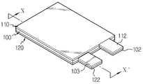
도 1은 본 발명의 바람직한 실시예에 따른 이차전지를 도시한 분해 사시도, 도 2는 도 1의 결합 사시도, 도 3은 도 2의 X-X'선에 따른 단면도이다.FIG. 1 is an exploded perspective view of a secondary battery according to a preferred embodiment of the present invention, FIG. 2 is an assembled perspective view of FIG. 1, and FIG. 3 is a sectional view taken along line X-X 'of FIG.
도 1 내지 도 3을 참조하면, 본 발명의 바람직한 실시예에 따른 이차전지는 전극 조립체가 내장된 셀 본체(100)와, 셀 본체(100)의 일면에 적층되는 제1 커버(110)와, 셀 본체(100)의 타면에 적층되는 제2 커버(120)를 포함한다.1 to 3, a secondary battery according to a preferred embodiment of the present invention includes a
셀 본체(100)는 그 내부에 제1 전극과 제2 전극이 교대로 적층되어 내장되고, 상기 제1 전극과 제2 전극 사이에 절연을 위한 세퍼레이터가 개재된 구조를 가진다. 상기 제1 전극과 제2 전극 중 어느 하나는 양극으로 사용되고, 다른 하나는 제2 전극으로 사용된다. 바람직하게, 셀 본체(100)는 판상체 형태의 장방형 몸체부(101)를 구비한다.The
제1 커버(110)와 제2 커버(120)는 금속성 소재로 이루어지고 셀 본체(100)에 대응하는 판상체 형태의 장방형 몸체부(111,121)를 구비한다. 제1 커버(110)는 셀 본체(100)의 일면에 적층되고 적어도 일부가 상기 제1 전극에 전기적으로 접속된다. 또한, 제2 커버(120)는 셀 본체(100)의 타면에 적층되고 적어도 일부가 상기 제2 전극에 전기적으로 접속된다.The
구체적으로, 셀 본체(100)의 장방형 몸체부(101)의 한쪽 가장자리에는 상기 제1 전극과 상기 제2 전극에 각각 연결된 제1 전극단자(102) 및 제2 전극단자(103)가 구비된다. 또한, 제1 커버(110)의 장방형 몸체부(111)의 한쪽 가장자리단과 제2 커버(120)의 장방형 몸체부(121)의 한쪽 가장자리단에는 각각 제1 접합부(112)와 제2 접합부(122)가 몸체부(111,121)와 일체로 돌출 형성된다. 바람직하게, 제1 접합부(112)와 제2 접합부(122)는 제1 전극단자(102)와 제2 전극단자(103)에 각각 용접됨으로써 접속된다.Specifically, a
제1 커버(110)에 있어, 제1 접합부(112)는 제1 전극단자(102)와 정대향할 수 있는 위치에 형성된다. 또한, 제2 커버(120)에 있어, 제2 접합부(122)는 제2 전극단자(103)와 정대향할 수 있는 위치에 형성된다.In the
도 4는 본 발명의 바람직한 실시예에 따른 이차전지 어셈블리의 제조방법이 수행되는 과정을 도시한 흐름도이다. 도면에 나타난 바와 같이 이차전지 어셈블리의 제조방법은 셀 본체(100)의 양면에 커버를 적층하는 공정(단계 S100)과, 커버의 일부를 전극단자에 용접하는 공정(단계 S110)과, 용접 부위에 형성되는 돌출부를 최소화하는 처리를 수행하는 공정(단계 S120)을 포함한다.FIG. 4 is a flowchart illustrating a method of manufacturing a secondary battery assembly according to an exemplary embodiment of the present invention. Referring to FIG. As shown in the drawing, a method of manufacturing a secondary battery assembly includes a step of laminating a cover on both sides of a cell body 100 (step S100), a step of welding a part of the cover to an electrode terminal (step S110) And a process of minimizing the protrusions to be formed (step S120).
먼저, 전극 조립체가 내장되고 외부에 제1 전극단자(102)와 제2 전극단자(103)가 인출된 셀 본체(100)를 준비한다. 여기서, 셀 본체(100)는 전체적으로 판상체의 구조를 갖는 것이 바람직하다.First, a cell
커버의 적층공정(단계 S100)에서는 셀 본체(100)의 양면에 각각 제1 커버(110)와 제2 커버(120)를 적층한다. 제1 커버(110)와 제2 커버(120)는 금속 소재로 이루어진 판상체의 구조를 가지며, 가장자리단에 접합부(112,122)가 돌출 형성된 구조를 갖는 것이 바람직하다.In the process of stacking the covers (step S100), the
용접 공정(단계 S110)에서는 커버의 접합부(112,122)를 전극단자(102,103)에 용접하여 전기적으로 접속한다. 구체적으로, 용접 공정에서는 제1 커버(110)의 한쪽 가장자리단에 돌출된 제1 접합부(112)와 제2 커버(120)의 한쪽 가장자리단에 돌출된 제2 접합부(122)를 각각 셀 본체(100)의 제1 전극단자(102)와 제2 전극단자(103)에 용접하여 단위 셀(200)을 형성한다.In the welding step (step S110), the
용접을 완료한 후에는 용접 부위에 존재하는 불필요한 부위를 제거하여 돌출부를 최소화하는 공정(단계 S120)을 수행한다.After completing the welding, a process of minimizing the projecting portion by removing unnecessary portions existing in the welding portion is performed (Step S120).
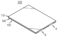
도 5에는 상기 과정을 통해 제조된 단위 셀(200)의 구성이 도시되어 있다. 도면에 나타난 바와 같이 단위 셀(200)은 셀 본체(100)의 양면에 제1 커버(110)와 제2 커버(120)가 적층되고, 제1 접합부(112)와 제2 접합부(122)에 의해 제1 커버(110)와 제2 커버(120)가 셀 본체(100)에 연결된 구조를 가진다.FIG. 5 shows the structure of the
도 6에는 본 발명의 바람직한 실시예에 따른 이차전지 어셈블리의 구성이 도시되어 있다. 도면에 나타난 바와 같이 이차전지 어셈블리는 소정의 고정 프레임(300)에 의해 지지되도록 복수개의 단위 셀(200)이 적층되고, 적층 방향을 따라 제1 커버(110)와 제2 커버(120)가 교호적으로 배치된 구조를 갖는다.FIG. 6 shows a configuration of a secondary battery assembly according to a preferred embodiment of the present invention. As shown in the drawing, a plurality of
전술한 바와 같이 단위 셀(200)은 셀 본체(100)의 양면에 제1 커버(110)와 제2 커버(120)가 적층되고, 제1 커버(110)와 제2 커버(120)가 셀 본체(100)의 해당 전극에 접속된 구조를 가진다.As described above, the
서로 다른 단위 셀(200)들 간에 제1 커버(110)와 제2 커버(120)가 접촉됨으로써 복수개의 단위 셀(200)은 적층과 동시에 직렬 연결이 이루어진다.The
상기와 같은 구성을 갖는 본 발명에 따른 이차전지 어셈블리는 제1 커버(110)와 제2 커버(120)를 매개로 단위 셀(200)들 간에 직렬 연결이 이루어지므로 단위 셀(200)들의 적층 공정만으로 직렬 연결이 이루어질 수 있다. 또한, 제1 커버(110)와 제2 커버(120)가 셀 본체(100)의 전극에 연결된 구조에 의해 셀의 온도특성을 개선할 수 있는 현저한 효과가 있다.Since the secondary battery assembly according to the present invention having the above-described structure is connected in series between the
이상에서 본 발명은 비록 한정된 실시예와 도면에 의해 설명되었으나, 본 발명은 이것에 의해 한정되지 않으며 본 발명이 속하는 기술분야에서 통상의 지식을 가진 자에 의해 본 발명의 기술사상과 아래에 기재될 특허청구범위의 균등범위 내에서 다양한 수정 및 변형이 가능함은 물론이다.While the present invention has been particularly shown and described with reference to exemplary embodiments thereof, it is to be understood that the invention is not to be limited to the details thereof and that various changes and modifications will be apparent to those skilled in the art. And various modifications and variations are possible within the scope of the appended claims.
100: 셀 본체 102: 제1 전극단자
103: 제2 전극단자 110: 제1 커버
112: 제1 접합부 120: 제2 커버
122: 제2 접합부 200: 단위 셀
300: 고정 프레임100: cell body 102: first electrode terminal
103: second electrode terminal 110: first cover
112: first joint 120: second cover
122: second junction 200: unit cell
300: Fixed frame
Claims (10)
상기 셀 본체의 일면에 적층되고 적어도 일부가 상기 제1 전극에 전기적으로 연결된 제1 셀 커버; 및
상기 셀 본체의 타면에 적층되고 적어도 일부가 상기 제2 전극에 전기적으로 접속된 제2 셀 커버;를 포함하는 이차전지.A cell body having an electrode assembly in which a first electrode, a separator, and a second electrode are alternately stacked;
A first cell cover stacked on one side of the cell body and at least a part of which is electrically connected to the first electrode; And
And a second cell cover laminated on the other surface of the cell body and at least a part of which is electrically connected to the second electrode.
상기 셀 본체의 한쪽 가장자리에는 상기 제1 전극과 상기 제2 전극에 각각 연결된 제1 전극단자 및 제2 전극단자가 구비되고,
상기 제1 셀 커버의 한쪽 가장자리단과 상기 제2 셀 커버의 한쪽 가장자리단에는 각각 제1 접합부와 제2 접합부가 돌출 형성되고,
상기 제1 접합부와 제2 접합부가 상기 제1 전극단자와 제2 전극단자에 각각 용접되어 접속된 것을 특징으로 하는 이차전지.The method according to claim 1,
Wherein the first electrode terminal and the second electrode terminal are respectively connected to the first electrode and the second electrode at one edge of the cell body,
A first joint portion and a second joint portion are protruded from one edge of the first cell cover and one edge of the second cell cover, respectively,
Wherein the first joint portion and the second joint portion are welded to the first electrode terminal and the second electrode terminal, respectively.
상기 제1 셀 커버와 상기 제2 셀 커버는 금속성 소재로 이루어지고,
상기 제1 접합부와 제2 접합부가 각각 상기 제1 셀 커버와 상기 제2 셀 커버에 일체화된 것을 특징으로 하는 이차전지.3. The method of claim 2,
Wherein the first cell cover and the second cell cover are made of a metallic material,
Wherein the first joint portion and the second joint portion are integrated with the first cell cover and the second cell cover, respectively.
상기 셀 본체는 판상체 형태로 이루어지고,
상기 제1 셀 커버와 상기 제2 셀 커버는 상기 셀 본체의 두께 방향 양면에 적층된 것을 특징으로 하는 이차전지.The method according to claim 1,
The cell body is in the form of a plate,
Wherein the first cell cover and the second cell cover are laminated on both surfaces in the thickness direction of the cell body.
(b) 상기 셀 본체의 양면에 각각 제1 셀 커버와 제2 셀 커버를 적층하는 단계;
(c) 상기 제1 셀 커버의 한쪽 가장자리단에 돌출된 제1 접합부와 상기 제2 셀 커버의 한쪽 가장자리단에 돌출된 제2 접합부를 각각 상기 제1 전극단자와 상기 제2 전극단자에 용접하여 단위 셀을 형성하는 단계; 및
(d) 용접이 완료된 서로 다른 단위 셀들을 적층하되, 적층 방향을 따라 제1 셀 커버와 제2 셀 커버가 교호적으로 배치되도록 상기 단위 셀들을 적층하는 단계;를 포함하는 이차전지의 제조방법.(a) an electrode assembly in which a first electrode, a separator and a second electrode are alternately stacked, and a first electrode terminal and a second electrode terminal connected to the first electrode and the second electrode, respectively, Preparing a cell body;
(b) stacking a first cell cover and a second cell cover on both sides of the cell body, respectively;
(c) a first joint portion protruding from one edge of the first cell cover and a second joint portion protruding from one edge of the second cell cover are welded to the first electrode terminal and the second electrode terminal, respectively Forming a unit cell; And
(d) stacking the unit cells so that the first cell cover and the second cell cover are alternately disposed along the stacking direction, wherein the unit cells are welded together.
상기 용접을 완료한 후 용접 부위에 형성된 돌출부를 제거하는 단계;를 더 포함하는 것을 특징으로 하는 이차전지의 제조방법.6. The method of claim 5, wherein in step (c)
And removing the protrusion formed on the welded portion after completing the welding.
제1 전극, 세퍼레이터 및 제2 전극이 교대로 적층된 전극 조립체가 내장된 셀 본체와, 상기 셀 본체의 일면에 적층되고 적어도 일부가 상기 제1 전극에 전기적으로 연결된 제1 셀 커버와, 상기 셀 본체의 타면에 적층되고 적어도 일부가 상기 제2 전극에 전기적으로 접속된 제2 셀 커버를 구비한 단위 셀;를 포함하고,
상기 단위 셀이 복수개 적층되고, 적층 방향을 따라 제1 셀 커버와 제2 셀 커버가 교호적으로 배치된 것을 특징으로 하는 이차전지 어셈블리.1. A secondary battery assembly comprising a plurality of unit cells,
A first cell cover which is laminated on one surface of the cell body and at least a part of which is electrically connected to the first electrode; And a second cell cover which is stacked on the other surface of the body and at least a part of which is electrically connected to the second electrode,
Wherein a plurality of the unit cells are stacked, and a first cell cover and a second cell cover are alternately arranged along the stacking direction.
상기 셀 본체의 한쪽 가장자리에는 상기 제1 전극과 상기 제2 전극에 각각 연결된 제1 전극단자 및 제2 전극단자가 구비되고,
상기 제1 셀 커버의 한쪽 가장자리단과 상기 제2 셀 커버의 한쪽 가장자리단에는 각각 제1 접합부와 제2 접합부가 돌출 형성되고,
상기 제1 접합부와 제2 접합부가 상기 제1 전극단자와 제2 전극단자에 각각 용접되어 접속된 것을 특징으로 하는 이차전지 어셈블리.8. The method of claim 7,
Wherein the first electrode terminal and the second electrode terminal are respectively connected to the first electrode and the second electrode at one edge of the cell body,
A first joint portion and a second joint portion are protruded from one edge of the first cell cover and one edge of the second cell cover, respectively,
Wherein the first joint portion and the second joint portion are welded to the first electrode terminal and the second electrode terminal, respectively.
상기 제1 셀 커버와 상기 제2 셀 커버는 금속성 소재로 이루어지고,
상기 제1 접합부와 제2 접합부가 각각 상기 제1 셀 커버와 상기 제2 셀 커버에 일체화된 것을 특징으로 하는 이차전지 어셈블리.8. The method of claim 7,
Wherein the first cell cover and the second cell cover are made of a metallic material,
Wherein the first joint portion and the second joint portion are integrated with the first cell cover and the second cell cover, respectively.
상기 셀 본체는 판상체 형태로 이루어지고,
상기 제1 셀 커버와 상기 제2 셀 커버는 상기 셀 본체의 두께 방향 양면에 적층된 것을 특징으로 하는 이차전지 어셈블리.8. The method of claim 7,
The cell body is in the form of a plate,
Wherein the first cell cover and the second cell cover are stacked on both sides in the thickness direction of the cell body.
Priority Applications (1)
| Application Number | Priority Date | Filing Date | Title |
|---|---|---|---|
| KR1020120138015A KR101549171B1 (en) | 2012-11-30 | 2012-11-30 | Improved secondary battery assembly for connection structure of electrode, secondary battery for the same and fabrication method thereof |
Applications Claiming Priority (1)
| Application Number | Priority Date | Filing Date | Title |
|---|---|---|---|
| KR1020120138015A KR101549171B1 (en) | 2012-11-30 | 2012-11-30 | Improved secondary battery assembly for connection structure of electrode, secondary battery for the same and fabrication method thereof |
Publications (2)
| Publication Number | Publication Date |
|---|---|
| KR20140070032A true KR20140070032A (en) | 2014-06-10 |
| KR101549171B1 KR101549171B1 (en) | 2015-09-01 |
Family
ID=51125023
Family Applications (1)
| Application Number | Title | Priority Date | Filing Date |
|---|---|---|---|
| KR1020120138015A KR101549171B1 (en) | 2012-11-30 | 2012-11-30 | Improved secondary battery assembly for connection structure of electrode, secondary battery for the same and fabrication method thereof |
Country Status (1)
| Country | Link |
|---|---|
| KR (1) | KR101549171B1 (en) |
Family Cites Families (2)
| Publication number | Priority date | Publication date | Assignee | Title |
|---|---|---|---|---|
| JP4961669B2 (en) * | 2005-01-31 | 2012-06-27 | 日本電気株式会社 | Battery pack structure |
| JP4501905B2 (en) * | 2006-07-19 | 2010-07-14 | トヨタ自動車株式会社 | Assembled battery |
-
2012
- 2012-11-30 KR KR1020120138015A patent/KR101549171B1/en active IP Right Grant
Also Published As
| Publication number | Publication date |
|---|---|
| KR101549171B1 (en) | 2015-09-01 |
Similar Documents
| Publication | Publication Date | Title |
|---|---|---|
| KR101053208B1 (en) | Battery module of improved welding reliability and battery pack employed with the same | |
| JP4519063B2 (en) | Secondary battery | |
| US9548475B2 (en) | Battery cell of irregular structure and battery module employed with the same | |
| EP2849275B1 (en) | Battery module including high-efficiency cooling structure | |
| US9203065B2 (en) | Battery module | |
| KR101125592B1 (en) | High Capacity Battery Cell of High Life Characteristics and Safety | |
| EP2595238B1 (en) | Battery pack having compact structure | |
| JP5175265B2 (en) | Lithium secondary battery with improved safety and capacity | |
| KR100873308B1 (en) | High Capacity Battery Cell Employed with Two or More Unit Cells | |
| KR100866767B1 (en) | Safety Kit for Secondary Battery | |
| JP4918242B2 (en) | Secondary battery | |
| US9331313B2 (en) | Battery pack of compact structure | |
| KR20050121907A (en) | Secondary battery and electrodes assembly using the same | |
| JP2007019017A (en) | Secondary cell | |
| KR102397122B1 (en) | Battery Module | |
| US20160164051A1 (en) | Secondary battery and battery pack including the same | |
| KR102055852B1 (en) | Pouch-typed secondary battery comprising modified leads and battery module comprising the same | |
| KR20110005595A (en) | Battery module | |
| KR20120074415A (en) | Unit module of novel structure and battery module comprising the same | |
| KR20120074425A (en) | Battery module and battery pack employed with the same | |
| KR20180126534A (en) | Multi-joint battery module | |
| US20110287303A1 (en) | Electrode assembly, rechargeable battery including the same, and method of manufacturing an electrode thereof | |
| JP2014524637A (en) | Single cell and battery for battery | |
| JP2014527262A (en) | Single cell and battery for battery | |
| US20140255761A1 (en) | Battery cell, manufacturing method thereof, and battery module including the same |
Legal Events
| Date | Code | Title | Description |
|---|---|---|---|
| A201 | Request for examination | ||
| E902 | Notification of reason for refusal | ||
| E701 | Decision to grant or registration of patent right | ||
| GRNT | Written decision to grant | ||
| FPAY | Annual fee payment |
Payment date: 20180619 Year of fee payment: 4 |