KR20140064609A - Cyclotron - Google Patents
Cyclotron Download PDFInfo
- Publication number
- KR20140064609A KR20140064609A KR1020130092515A KR20130092515A KR20140064609A KR 20140064609 A KR20140064609 A KR 20140064609A KR 1020130092515 A KR1020130092515 A KR 1020130092515A KR 20130092515 A KR20130092515 A KR 20130092515A KR 20140064609 A KR20140064609 A KR 20140064609A
- Authority
- KR
- South Korea
- Prior art keywords
- yoke
- cyclotron
- pole
- ion beam
- hole
- Prior art date
Links
Images

Classifications
-
- H—ELECTRICITY
- H05—ELECTRIC TECHNIQUES NOT OTHERWISE PROVIDED FOR
- H05H—PLASMA TECHNIQUE; PRODUCTION OF ACCELERATED ELECTRICALLY-CHARGED PARTICLES OR OF NEUTRONS; PRODUCTION OR ACCELERATION OF NEUTRAL MOLECULAR OR ATOMIC BEAMS
- H05H7/00—Details of devices of the types covered by groups H05H9/00, H05H11/00, H05H13/00
- H05H7/02—Circuits or systems for supplying or feeding radio-frequency energy
-
- H—ELECTRICITY
- H05—ELECTRIC TECHNIQUES NOT OTHERWISE PROVIDED FOR
- H05H—PLASMA TECHNIQUE; PRODUCTION OF ACCELERATED ELECTRICALLY-CHARGED PARTICLES OR OF NEUTRONS; PRODUCTION OR ACCELERATION OF NEUTRAL MOLECULAR OR ATOMIC BEAMS
- H05H13/00—Magnetic resonance accelerators; Cyclotrons
- H05H13/005—Cyclotrons
-
- H—ELECTRICITY
- H05—ELECTRIC TECHNIQUES NOT OTHERWISE PROVIDED FOR
- H05H—PLASMA TECHNIQUE; PRODUCTION OF ACCELERATED ELECTRICALLY-CHARGED PARTICLES OR OF NEUTRONS; PRODUCTION OR ACCELERATION OF NEUTRAL MOLECULAR OR ATOMIC BEAMS
- H05H13/00—Magnetic resonance accelerators; Cyclotrons
-
- H—ELECTRICITY
- H05—ELECTRIC TECHNIQUES NOT OTHERWISE PROVIDED FOR
- H05H—PLASMA TECHNIQUE; PRODUCTION OF ACCELERATED ELECTRICALLY-CHARGED PARTICLES OR OF NEUTRONS; PRODUCTION OR ACCELERATION OF NEUTRAL MOLECULAR OR ATOMIC BEAMS
- H05H7/00—Details of devices of the types covered by groups H05H9/00, H05H11/00, H05H13/00
- H05H7/12—Arrangements for varying final energy of beam
- H05H2007/122—Arrangements for varying final energy of beam by electromagnetic means, e.g. RF cavities
Abstract
Description
본 발명은, 번처를 가지는 사이클로트론에 관한 것이다.The present invention relates to a cyclotron having a soot.
종래, 사이클로트론에 관한 기술문헌으로서, 예를 들면 일본 특허공개공보 2004-31115호가 알려져 있다. 이 공보에는, 외부 이온원을 가지는 사이클로트론에 있어서, 외부 이온원으로부터 송출된 이온빔을 사이클로트론 중심으로 입사시키는 전단에 번처를 설치하는 것이 기재되어 있다.Conventionally, as a technical literature on cyclotron, for example, Japanese Patent Application Laid-Open No. 2004-31115 is known. In this publication, it is described that, in a cyclotron having an external ion source, a bundle is provided at the front end for making the ion beam emitted from the external ion source enter the center of the cyclotron.
이와 같은 번처는, 고주파 전장에 있어서 이온빔의 가속을 효율적으로 행하기 위하여 이용된다. 즉, 고주파 전장에 있어서는 전위차가 주기적으로 변화되기 때문에, 이온빔에는 진행방향(위상방향)에 있어서 전위차에 의하여 가속되는 부위와 가속되지 않는 부위가 발생한다. 이로 인하여, 이온빔이 가속되는 부위에 집속하도록 진행방향의 밀도를 조정하는 번처를 설치함으로써, 빔 효율의 향상이 도모되고 있다.Such a sheath is used for efficiently accelerating the ion beam in the high frequency electric field. That is, in the high frequency electric field, since the potential difference is periodically changed, a portion accelerated by the potential difference in the advancing direction (phase direction) and a portion not accelerated are generated in the ion beam. Thus, the beam efficiency is improved by providing a bundle for adjusting the density of the traveling direction so as to converge on the region where the ion beam is accelerated.
(특허문헌)(Patent Literature)
특허문헌 1: 일본 특허공개공보 2004-31115호Patent Document 1: Japanese Patent Application Laid-Open No. 2004-31115
그런데, 번처에 의하여 이온빔의 진행방향의 밀도를 조정하면, 집속된 이온간에 공간전하 효과에 의한 반발이 발생하여, 번칭 효과가 저하된다. 이러한 공간전하 효과는 이온빔의 전류치가 높을수록 강하게 나타난다. 공간전하 효과에 의하여 번칭 효과가 저하됨으로써, 사이클로트론에 있어서의 빔 효율이 저하되는 문제가 있었다.However, when the density of the direction of the ion beam is adjusted by the forklift, repulsion due to the space charge effect occurs between the focused ions, and the bunching effect is lowered. This space charge effect is stronger as the current value of the ion beam is higher. There is a problem that the beaming efficiency in the cyclotron is lowered due to the reduction of the bunching effect due to the space charge effect.
따라서, 본 발명은, 빔 효율의 향상을 도모할 수 있는 사이클로트론을 제공하는 것을 목적으로 한다.Therefore, it is an object of the present invention to provide a cyclotron capable of improving beam efficiency.
상기 과제를 해결하기 위하여, 본 발명은, 중공의 요크와, 요크 내에 배치된 제1 폴 및 제2 폴과, 이온을 생성하는 이온원과, 요크 내에 적어도 일부가 들어가고, 이온원으로부터 송출된 이온빔의 진행방향의 밀도를 조정하는 번처와, 번처를 통과한 이온빔을 편향하여, 미디안플레인에 입사시키는 인플렉터를 구비하는 것을 특징으로 한다.According to an aspect of the present invention, there is provided a yoke including a hollow yoke, a first pole and a second pole disposed in the yoke, an ion source for generating ions, at least a portion of the ion source for generating ions, And an inflator for deflecting the ion beam passed through the bundle and making the ion beam incident on the median plane.
이 사이클로트론에 의하면, 번처의 적어도 일부가 요크 내에 들어가 있으므로, 번처를 요크의 밖에 배치하는 종래의 구성과 비교하여, 번처와 인플렉터와의 거리를 짧게 할 수 있다. 이로 인하여, 번처에 의하여 이온빔의 진행방향(위상방향)의 밀도를 조정한 후, 공간전하 효과에 의하여 이온빔이 확산되기 전에 인플렉터로 도달시킬 수 있으므로, 높은 번칭 효과를 가지는 상태로 이온빔을 가속할 수 있어, 빔 효율의 향상을 도모할 수 있다.According to this cyclotron, since at least a part of the bundle is contained in the yoke, the distance between the bundle and the inflator can be shortened as compared with the conventional configuration in which the bundle is disposed outside the yoke. As a result, after the density of the advancing direction (phase direction) of the ion beam is adjusted by the forklift, the ion beam can be reached by the inflator before the ion beam is diffused by the space charge effect. So that the beam efficiency can be improved.
본 발명에 관한 사이클로트론에 있어서, 번처의 적어도 일부는, 제1 폴 내에 들어가 있어도 된다.In the cyclotron according to the present invention, at least a part of the gathering may be contained in the first pole.
이 사이클로트론에 의하면, 번처와 인플렉터와의 거리를 한층 짧게 하는 것이 가능하게 되므로, 대형의 사이클로트론이어도, 번처 및 인플렉터를 적절한 가까운 위치에 배치할 수 있어, 빔 효율의 향상을 도모할 수 있다.According to this cyclotron, it is possible to further shorten the distance between the forklift and the injector, so that even if the large size cyclotron is used, it is possible to arrange the inlays and the injector at appropriate close positions, thereby improving the beam efficiency.
본 발명에 관한 사이클로트론에 있어서, 번처의 전극부는, 인플렉터측의 단부에 위치하고 있어도 된다.In the cyclotron according to the present invention, the electrode portion of the elongated portion may be located at the end of the inflator side.
이 사이클로트론에 의하면, 이온빔의 진행방향의 밀도를 조정하는 전극부가 인플렉터측의 단부에 위치하므로, 전극부가 인플렉터측의 단부 이외에 위치하는 경우와 비교하여, 공간전하 효과에 의하여 이온빔이 확산되기 전에 인플렉터로 도달시킬 수 있어, 빔 효율의 향상에 유리하다.According to this cyclotron, since the electrode portion for adjusting the density of the advancing direction of the ion beam is located at the end portion on the side of the inflector, compared with the case where the electrode portion is located other than the end portion on the inflector side, It can be reached by the inflator, which is advantageous for the improvement of the beam efficiency.
본 발명에 관한 사이클로트론에 있어서, 요크는, 번처의 적어도 일부가 들어가는 제1 구멍과, 인플렉터에 대하여 제1 구멍과 반대측에 형성된 제2 구멍을 가지고 있어도 된다.In the cyclotron according to the present invention, the yoke may have a first hole into which at least a part of the buttress enters, and a second hole formed opposite to the first hole with respect to the injector.
이 사이클로트론에 의하면, 제2 구멍을 갖지 않는 경우와 비교하여, 요크의 대칭성을 유지할 수 있으므로, 미디안플레인에 있어서의 자장의 제어가 용이해진다.According to this cyclotron, the symmetry of the yoke can be maintained as compared with the case where the second hole is not provided, so that the control of the magnetic field in the median plane is facilitated.
본 발명에 의하면, 빔 효율의 향상을 도모할 수 있는 사이클로트론을 제공할 수 있다.According to the present invention, it is possible to provide a cyclotron capable of improving the beam efficiency.
도 1은 본 발명에 관한 사이클로트론의 일 실시형태를 나타내는 단면도이다.
도 2는 도 1의 번처를 나타내는 단면도이다.1 is a cross-sectional view showing an embodiment of a cyclotron according to the present invention.
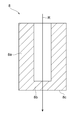
Fig. 2 is a cross-sectional view showing the bundle of Fig. 1;
이하, 본 발명의 적합한 실시형태에 대하여, 도면을 참조하여 상세하게 설명한다.Best Mode for Carrying Out the Invention Hereinafter, a preferred embodiment of the present invention will be described in detail with reference to the drawings.
도 1에 나타내는 바와 같이, 본 실시형태에 관한 사이클로트론(1)은, 이온원(2)으로부터 송출된 이온빔(R)을 가속하여 출사하는 가로배치형의 가속기이다. 이온빔(R)을 구성하는 이온으로서는, 예를 들면 양자(陽子)나 중이온 등을 들 수 있다.As shown in Fig. 1, the
이러한 사이클로트론(1)은, 예를 들면, PET[Positron Emission Tomography]용 사이클로트론, 붕소 중성자 포착요법용 사이클로트론, RI[Radio Isotope]제제용 사이클로트론, 중성자원용 사이클로트론, 양자용 사이클로트론, 중양자용 사이클로트론으로서 이용된다.Such a
사이클로트론(1)은, 이온원(2), 내부에 소정의 공간이 형성된 중공의 요크(3), 폴(4), 코일(5), 번처(8), 및 인플렉터(9)를 구비하고 있다.The
이온원(2)은, 요크(3)의 외부에 설치되고, 이온을 생성하는 외부 이온원이다. 도 1에서는, 원반형의 사이클로트론(1)의 중심축(C) 상에 이온원(2)이 설치되어 있지만, 반드시 중심축(C) 상에 이온원(2)을 설치할 필요는 없다. 이온원(2)은, 사이클로트론(1)의 상측이 아닌 하측에 설치되어 있어도 된다. 또, 이온원(2)의 일부 또는 전체가 요크(3) 내에 들어가 있어도 된다.The
폴(4)은, 상측 폴(제1 폴)(6) 및 하측 폴(제2 폴)(7)로 이루어지는 자극이다. 상측 폴(6)은 요크(3)의 내부의 상면(3a)에 배치되어 있고, 하측 폴(7)은 요크(3)의 내부의 하면(3b)에 배치되어 있다. 상측 폴(6) 및 하측 폴(7)의 주위에는 원환형상의 코일(5)이 배치되어 있고, 코일(5)에 대한 전류공급에 의하여 상측 폴(6) 및 하측 폴(7)의 사이에 연직방향의 자장이 발생한다. 이들의 상측 폴(6) 및 하측 폴(7)의 사이에, 이온빔(R)이 주회하는 미디안플레인(P)이 형성된다.The
또, 사이클로트론(1)은, 디이(Dee)전극(도시하지 않음)을 구비하고 있다. 디이전극은, 중심축(C)의 연재방향으로부터 보아 부채형으로 형성되어 있다. 디이전극의 내부에는, 중심축(C)의 둘레방향으로 관통된 공동(空洞)이 형성되어 있고, 그 공동 내에 미디안플레인(P)이 위치하고 있다. 사이클로트론(1)에서는, 디이전극에 교류 전류를 공급함으로써 공동 내에 고주파 전장을 발생시켜, 고주파 전장에 있어서의 전위차의 주기적 변화에 의하여 이온빔(R)을 반복하여 가속시킨다.The
번처(8)는, 이온빔(R)의 진행방향(위상방향)의 밀도를 조정하는 것이다. 번처(8)는, 고주파 전장에 있어서의 전위차의 주기적 변화에 대응하도록, 이온빔(R)을 진행방향의 소정간격으로 집속시킴으로써, 사이클로트론(1)의 빔 효율을 높인다.The
번처(8)는, 중공의 요크(3) 내에 배치되어 있다. 구체적으로는, 번처(8)는, 요크(3)에 형성된 번처용의 제1 구멍(3c)의 내부에 배치되어 있다. 제1 구멍(3c)은, 요크(3) 내부의 공간과 요크(3)의 외부를 연통시키도록, 중심축(C)을 따라 형성된 관통공이다. 이온원(2)으로부터 송출된 이온빔(R)은, 제1 구멍(3c)을 지나 번처(8)에 도달한다.The
또, 번처(8)의 일부는, 상측 폴(6)에 형성된 오목부(6a) 내에 들어가 있다. 즉, 번처(8)는, 그 대부분이 요크(3)의 제1 구멍(3c)에 수용됨과 함께, 그 일부(상측 폴(6)측)가 상측 폴(6)의 오목부(6a) 내에 들어가 있다. 상측 폴(6)의 오목부(6a)는, 요크(3)의 제1 구멍(3c)에 대응하여 형성되고, 중심축(C)을 따라 하방향으로 오목하다.A part of the
다만, 요크(3)는, 인플렉터(9)에 대하여 제1 구멍(3c)의 반대측에 형성된 제2 구멍(3e)을 가지고 있다. 제2 구멍(3e)은, 인플렉터(9)에 대하여 제1 구멍(3c)과 대략 대칭으로 형성된 관통공이다. 즉, 제2 구멍(3e)은, 요크(3)의 대칭성을 유지하기 위하여, 크기나 형상이 가능한 한 제1 구멍(3c)과 동일해지도록 형성되어 있다.The
마찬가지로, 하측 폴(7)은, 인플렉터(9)에 대하여 상측 폴(6)의 오목부(6a)와 대략 대칭으로 형성된 오목부(7a)를 가지고 있다. 오목부(7a)는, 요크(3)의 제2 구멍(3e)에 대응하여 형성되고, 중심축(C)을 따라 상방향으로 오목하다.Likewise, the
도 2는, 번처(8)를 나타내는 단면도이다. 도 2에 나타내는 바와 같이, 번처(8)는, 원통형상의 본체부(8a)와, 원통형상의 본체부(8a)의 인플렉터(9)측의 개구를 폐쇄하고 있는 전극부(8b)를 가지고 있다. 즉, 전극부(8b)는, 번처(8)의 인플렉터(9)측의 단부에 위치하고 있다. 본체부(8a) 및 전극부(8b)는 일체의 부재이며, 예를 들면 구리 등의 도전재료로 구성되어 있다.Fig. 2 is a cross-sectional view showing the
번처(8)는, 인플렉터(9)와 소정의 거리가 되도록 배치되어 있다. 구체적으로는, 번처(8)는, 인플렉터(9)측의 단면(8c)과 인플렉터(9)와의 거리가 10cm~30cm가 되도록 배치되는 것이 바람직하다.The
번처(8)의 단면(8c)과 인플렉터(9)가 10cm 이상 떨어짐으로써, 인플렉터(9)에 도달할 때까지의 동안에 이온빔(R)의 밀도를 조정하는 번칭 효과를 충분히 얻을 수 있다. 또, 번처(8)의 단면(8c)과 인플렉터(9)가 30cm보다 가까움으로써, 공간전하 효과에 의하여 번칭 효과가 저하되기 전에 인플렉터(9)에 도달할 수 있다.It is possible to sufficiently obtain a bunching effect of adjusting the density of the ion beam R until the
번처(8)에는, 도시하지 않은 전원으로부터 전류가 공급되고 있다. 이온빔(R)은, 원통형상의 본체부(8a)의 내부를 진행하여 전극부(8b)를 통과함으로써, 진행방향의 밀도의 조정이 행하여진다. 번처(8)를 통과한 이온빔(R)은, 인플렉터(9)를 향하여 진행한다.A current is supplied from the power source (not shown) to the
다만, 번처(8)의 구조는, 상술한 것에 한정되지 않는다. 예를 들면, 전극부(8b)는, 본체부(8a)의 인플렉터(9)측의 단부가 아닌, 반대측의 단부나 본체부(8a)의 중간부분에 설치되어 있어도 된다. 이 경우에는, 전극부(8b)와 인플렉터(9)와의 거리가 10cm~30cm인 것이 바람직하다.However, the structure of the
인플렉터(9)는, 이온빔(R)을 미디안플레인(P)에 입사(도입)시키는 것이다. 인플렉터(9)는, 전원(도시하지 않음)으로부터 전류가 공급되어 있고, 사이클로트론(1)의 중심축(C)을 따라 진행하는 이온빔(R)을 편향하여 미디안플레인(P)에 입사시킨다. 인플렉터(9)는, 상측 폴(6) 및 하측 폴(7)의 사이에서 사이클로트론(1)의 대략 중심에 배치되어 있다.The
인플렉터(9)를 지나 미디안플레인(P)에 입사된 이온빔(R)은, 폴(4)의 자장 및 디이전극의 전장의 작용에 의하여 나선형상의 궤도를 그리면서 가속한다. 이온빔(R)은 충분히 가속된 후, 궤도로부터 인출되어 외부로 출력된다.The ion beam R that is incident on the median plane P through the
이상 설명한 본 실시형태에 관한 사이클로트론(1)에 의하면, 번처(8)가 요크(3) 내에 배치되어 있으므로, 번처(8)를 요크(3)의 밖에 설치하는 종래의 구성과 비교하여, 번처(8)와 인플렉터(9)와의 거리를 짧게 할 수 있다. 이로 인하여, 번처(8)에 의하여 이온빔(R)의 진행방향(위상방향)의 밀도를 조정한 후, 공간전하 효과에 의하여 이온빔(R)이 확산되기 전에 인플렉터(9)로 도달시킬 수 있으므로, 높은 번칭 효과를 가지는 상태로 이온빔(R)을 가속할 수 있어, 빔 효율의 향상을 도모할 수 있다.In the
또, 이 사이클로트론(1)에서는, 번처(8)의 일부가 상측 폴(6)의 오목부(6a) 내에 들어가 있으므로, 번처(8)와 인플렉터(9)와의 거리를 한층 짧게 할 수 있다. 따라서, 이 사이클로트론(1)에 의하면, 대형의 사이클로트론이어도, 번처(8) 및 인플렉터(9)를 적절한 간격으로 배치할 수 있어, 빔 효율의 향상이 도모된다.In this
또한, 이 사이클로트론(1)에 의하면, 번처(8)의 전극부(8b)가 본체부(8a)의 인플렉터(9)측의 단부에 위치하고 있으므로, 전극부(8b)가 인플렉터(9)측의 단부 이외에 위치하는 경우와 비교하여, 공간전하 효과에 의하여 이온빔(R)이 확산되기 전에 인플렉터(9)로 도달시킬 수 있어, 빔 효율의 향상에 유리하다.Since the
또, 이 사이클로트론(1)에서는, 인플렉터(9)에 대하여 제1 구멍(3c)의 반대측에 형성된 제2 구멍(3e)을 가지므로, 제2 구멍(3e)를 갖지 않는 경우와 비교하여, 요크(3)의 대칭성을 유지할 수 있어, 미디안플레인(P)에 있어서의 자장의 제어가 용이해진다.Since the
본 발명은, 상술한 실시형태에 한정되는 것은 아니다. 예를 들면, 이온빔(R)은, 요크의 하측으로부터 입사하여도 된다. 이 경우, 번처는, 요크 하측의 구멍에 배치되어, 하측 폴에 형성된 오목부에 들어가게 된다.The present invention is not limited to the above-described embodiments. For example, the ion beam R may be incident from below the yoke. In this case, the bundle is arranged in the hole in the lower side of the yoke and enters the recess formed in the lower pole.
다만, 번처는, 반드시 상측 폴 또는 하측 폴에 형성된 오목부에 들어갈 필요는 없다. 번처는, 상측 폴 또는 하측 폴에 이르지 않고, 요크에 형성된 구멍의 내부에 수용되어 있어도 된다. 또, 번처는, 적어도 일부가 요크 내에 들어가 있으면 되고, 나머지 부분이 요크 밖으로 돌출되어 있어도 된다.However, the bundle need not always enter the concave portion formed in the upper pole or the lower pole. The bundle may be accommodated in the hole formed in the yoke without reaching the upper pole or the lower pole. Further, at least a part of the bundle may be contained in the yoke, and the remaining part may protrude out of the yoke.
또, 요크에 있어서, 번처가 배치되지 않는 제2 구멍을 반드시 형성할 필요는 없다. 마찬가지로, 상측 폴 및 하측 폴 중 번처가 들어가지 않는 폴에 반드시 오목부를 형성할 필요는 없다.In the yoke, it is not always necessary to form the second hole in which the bunched portion is not disposed. Likewise, it is not always necessary to form the recesses in the pawls in which the upper and lower pawls do not enter the respective positions.
다만, 사이클로트론은, 가로배치형의 것이 아닌 세로배치형의 것을 채용하여도 된다. 이 경우에는, 상술한 실시형태의 설명에 있어서의 상하방향이 좌우방향으로 되고, 상측 폴 및 하측 폴은, 좌측 폴 및 우측 폴이 된다.However, the cyclotron may be a vertical arrangement type, not a horizontal arrangement type. In this case, the vertical direction in the above-described embodiment is the left-right direction, and the upper pole and the lower pole become the left pole and the right pole.
1: 사이클로트론 2: 이온원
3: 요크 3a: 상면
3b: 하면 3c: 제1 구멍
3e: 제2 구멍 4: 폴
5: 코일 6: 상측 폴(제1 폴)
6a: 오목부 7: 하측 폴(제2 폴)
8: 번처 8a: 본체부
8b: 전극부 8c: 단면
9: 인플렉터 P: 미디안플레인
R: 이온빔1: Cyclotron 2: Ion source
3:
3b: When 3c: 1st hole
3e: second hole 4: pole
5: coil 6: upper pole (first pole)
6a: recess 7: lower pole (second pole)
8:
8b:
9: Inflator P: Midian plane
R: ion beam
Claims (4)
상기 요크 내에 배치된 제1 폴 및 제2 폴과,
이온을 생성하는 이온원과,
상기 요크 내에 적어도 일부가 들어가고, 상기 이온원으로부터 송출된 이온빔의 진행방향의 밀도를 조정하는 번처와,
상기 번처를 통과한 이온빔을 편향하여, 미디안플레인에 입사시키는 인플렉터를 구비하는, 사이클로트론.With a hollow yoke,
A first pole and a second pole disposed in the yoke,
An ion source for generating ions,
At least a part of which enters the yoke and which regulates the density of the ion beam emitted from the ion source in the traveling direction,
And an inflator for deflecting the ion beam passing through the bundle and entering the medium plane.
상기 번처의 적어도 일부는, 상기 제1 폴 내에 들어가 있는 사이클로트론.The method according to claim 1,
Wherein at least a portion of the inlets is contained within the first pole.
상기 번처의 전극부는, 상기 인플렉터측의 단부에 위치하고 있는 사이클로트론.The method according to claim 1,
And the electrode portion of the bundle is located at the end of the inflator side.
상기 요크는, 상기 번처의 적어도 일부가 들어가는 제1 구멍과, 상기 인플렉터에 대하여 상기 제1 구멍과 대칭으로 형성된 제2 구멍을 가지는 사이클로트론.The method according to claim 1,
The yoke has a first hole into which at least a part of the above-mentioned inlets is inserted, and a second hole formed symmetrically with the first hole with respect to the injector.
Applications Claiming Priority (2)
| Application Number | Priority Date | Filing Date | Title |
|---|---|---|---|
| JP2012254346A JP2014102990A (en) | 2012-11-20 | 2012-11-20 | Cyclotron |
| JPJP-P-2012-254346 | 2012-11-20 |
Publications (1)
| Publication Number | Publication Date |
|---|---|
| KR20140064609A true KR20140064609A (en) | 2014-05-28 |
Family
ID=49354426
Family Applications (1)
| Application Number | Title | Priority Date | Filing Date |
|---|---|---|---|
| KR1020130092515A KR20140064609A (en) | 2012-11-20 | 2013-08-05 | Cyclotron |
Country Status (6)
| Country | Link |
|---|---|
| US (1) | US9000657B2 (en) |
| EP (1) | EP2734017B1 (en) |
| JP (1) | JP2014102990A (en) |
| KR (1) | KR20140064609A (en) |
| CN (1) | CN103841745B (en) |
| TW (1) | TWI523585B (en) |
Cited By (1)
| Publication number | Priority date | Publication date | Assignee | Title |
|---|---|---|---|---|
| KR20200093830A (en) * | 2019-01-29 | 2020-08-06 | 성균관대학교산학협력단 | Accelerated Mass Spectrometry Cyclotron System |
Families Citing this family (6)
| Publication number | Priority date | Publication date | Assignee | Title |
|---|---|---|---|---|
| JP5955709B2 (en) * | 2012-09-04 | 2016-07-20 | 住友重機械工業株式会社 | cyclotron |
| EP2811813B1 (en) * | 2013-06-04 | 2016-01-06 | Ion Beam Applications | Methods for adjusting the position of a main coil in a cyclotron |
| CN109874222B (en) * | 2017-12-06 | 2022-10-25 | 清华大学 | Drift tube, drift tube linear accelerator and drift tube processing method |
| WO2019242011A1 (en) * | 2018-06-22 | 2019-12-26 | 新瑞阳光粒子医疗装备(无锡)有限公司 | Synchrotron control method, apparatus, device, and storage medium |
| JP7458309B2 (en) * | 2020-12-11 | 2024-03-29 | 株式会社日立製作所 | Laser ion sources, circular accelerators and particle therapy systems |
| CN116156730B (en) * | 2023-01-09 | 2023-11-21 | 中国科学院近代物理研究所 | Structure of axial injector for cyclotron |
Family Cites Families (13)
| Publication number | Priority date | Publication date | Assignee | Title |
|---|---|---|---|---|
| GB2186736A (en) * | 1986-02-13 | 1987-08-19 | Marconi Co Ltd | Ion beam arrangement |
| US5227701A (en) * | 1988-05-18 | 1993-07-13 | Mcintyre Peter M | Gigatron microwave amplifier |
| BE1005530A4 (en) * | 1991-11-22 | 1993-09-28 | Ion Beam Applic Sa | Cyclotron isochronous |
| JP2925965B2 (en) | 1994-12-15 | 1999-07-28 | 住友重機械工業株式会社 | Method and apparatus for collecting charged particle beams |
| USH1758H (en) * | 1996-03-04 | 1998-11-03 | Malouf; Perry M. | Microwave amplifier having cross-polarized cavities |
| WO2000036633A1 (en) * | 1998-12-17 | 2000-06-22 | Jeol Usa, Inc. | In-line reflecting time-of-flight mass spectrometer for molecular structural analysis using collision induced dissociation |
| DE50114988D1 (en) * | 2000-08-17 | 2009-08-27 | Schwerionenforsch Gmbh | APPARATUS AND METHOD FOR ION RADIATION ACCELERATION AND ELECTRON RADIATION IMPULSE FORMING AND REINFORCEMENT |
| JP2004031115A (en) * | 2002-06-26 | 2004-01-29 | Matsushita Electric Ind Co Ltd | Phase width confining method and phase width confining device for beam accelerated by cyclotron |
| CA2574122A1 (en) * | 2004-07-21 | 2006-02-02 | Still River Systems, Inc. | A programmable radio frequency waveform generator for a synchrocyclotron |
| US7315140B2 (en) * | 2005-01-27 | 2008-01-01 | Matsushita Electric Industrial Co., Ltd. | Cyclotron with beam phase selector |
| US7888630B2 (en) * | 2006-04-06 | 2011-02-15 | Wong Alfred Y | Reduced size high frequency quadrupole accelerator for producing a neutralized ion beam of high energy |
| US7919765B2 (en) * | 2008-03-20 | 2011-04-05 | Varian Medical Systems Particle Therapy Gmbh | Non-continuous particle beam irradiation method and apparatus |
| US8106570B2 (en) * | 2009-05-05 | 2012-01-31 | General Electric Company | Isotope production system and cyclotron having reduced magnetic stray fields |
-
2012
- 2012-11-20 JP JP2012254346A patent/JP2014102990A/en active Pending
-
2013
- 2013-08-05 KR KR1020130092515A patent/KR20140064609A/en not_active Application Discontinuation
- 2013-08-06 TW TW102128112A patent/TWI523585B/en not_active IP Right Cessation
- 2013-08-13 CN CN201310351163.XA patent/CN103841745B/en not_active Expired - Fee Related
- 2013-10-11 EP EP13004888.7A patent/EP2734017B1/en active Active
- 2013-10-15 US US14/053,734 patent/US9000657B2/en not_active Expired - Fee Related
Cited By (1)
| Publication number | Priority date | Publication date | Assignee | Title |
|---|---|---|---|---|
| KR20200093830A (en) * | 2019-01-29 | 2020-08-06 | 성균관대학교산학협력단 | Accelerated Mass Spectrometry Cyclotron System |
Also Published As
| Publication number | Publication date |
|---|---|
| EP2734017A1 (en) | 2014-05-21 |
| US9000657B2 (en) | 2015-04-07 |
| CN103841745B (en) | 2016-12-28 |
| US20140139096A1 (en) | 2014-05-22 |
| EP2734017B1 (en) | 2018-06-13 |
| JP2014102990A (en) | 2014-06-05 |
| TW201422062A (en) | 2014-06-01 |
| TWI523585B (en) | 2016-02-21 |
| CN103841745A (en) | 2014-06-04 |
Similar Documents
| Publication | Publication Date | Title |
|---|---|---|
| KR20140064609A (en) | Cyclotron | |
| EP3180966B1 (en) | High frequency compact low-energy linear accelerator design | |
| Kuo et al. | On the development of a 15 mA direct current H− multicusp source | |
| Eshraqi et al. | The ESS linac | |
| CN112822830B (en) | Proton and light ion synchrotron, treatment system containing same and application | |
| JPWO2019142389A1 (en) | Accelerator and accelerator system | |
| JP4875400B2 (en) | High aspect ratio, high mass resolution analyzer magnet and system for ribbon ion beam | |
| EP3225084A1 (en) | Radio frequency cavities | |
| Gaur et al. | Beam dynamics and electromagnetic studies of a 3 MeV, 325 MHz radio frequency quadrupole accelerator | |
| Toosi et al. | Bubble structure in laser wake-field acceleration | |
| Ahrens et al. | Setup and performance of the RHIC injector accelerators for the 2007 run with gold ions | |
| Quax et al. | A high-current light-ion injector for tandem accelerators | |
| Maggiore et al. | An intrinsically safe facility for forefront research and training on nuclear technologies—An example of accelerator: the SPES cyclotron | |
| KR20190055178A (en) | Multiple-undulator small helical optical source | |
| JP6042226B2 (en) | Accelerator and Neutron Capture Therapy Device | |
| Setiniyaz et al. | Pushing the capture limit of thermionic gun linacs | |
| Spädtke et al. | Use of Simulations Based on Experimental Data | |
| Neufeld et al. | Positron injector of the VEPP-4M collider | |
| Lamy et al. | 60-GHz ECR ion sources | |
| Raparia et al. | Changes in LEBT/MEBT at the BNL 200 MeV Linac | |
| Sabato et al. | JACOW: Electron cloud build-up studies for FCC-ee | |
| Zimmermann et al. | The Large Hadron-Electron Collider (LHEC) at the LHC | |
| KR20210056143A (en) | Large Current Duo Plasmatron Ion Source for Photon Accelerator | |
| Biarrotte et al. | First beams produced by the SPIRAL2 injectors | |
| Clark et al. | Design and Construction of the Axial Injection System for the 88-Inch Cyclotron |
Legal Events
| Date | Code | Title | Description |
|---|---|---|---|
| A201 | Request for examination | ||
| E902 | Notification of reason for refusal | ||
| E601 | Decision to refuse application |