KR20140063656A - Method and apparatus for feeding joining elements - Google Patents
Method and apparatus for feeding joining elements Download PDFInfo
- Publication number
- KR20140063656A KR20140063656A KR1020147005531A KR20147005531A KR20140063656A KR 20140063656 A KR20140063656 A KR 20140063656A KR 1020147005531 A KR1020147005531 A KR 1020147005531A KR 20147005531 A KR20147005531 A KR 20147005531A KR 20140063656 A KR20140063656 A KR 20140063656A
- Authority
- KR
- South Korea
- Prior art keywords
- magazine
- filling station
- section
- coupling
- tubular section
- Prior art date
Links
Images


Classifications
-
- B—PERFORMING OPERATIONS; TRANSPORTING
- B21—MECHANICAL METAL-WORKING WITHOUT ESSENTIALLY REMOVING MATERIAL; PUNCHING METAL
- B21J—FORGING; HAMMERING; PRESSING METAL; RIVETING; FORGE FURNACES
- B21J15/00—Riveting
- B21J15/10—Riveting machines
- B21J15/30—Particular elements, e.g. supports; Suspension equipment specially adapted for portable riveters
- B21J15/32—Devices for inserting or holding rivets in position with or without feeding arrangements
-
- B—PERFORMING OPERATIONS; TRANSPORTING
- B23—MACHINE TOOLS; METAL-WORKING NOT OTHERWISE PROVIDED FOR
- B23P—METAL-WORKING NOT OTHERWISE PROVIDED FOR; COMBINED OPERATIONS; UNIVERSAL MACHINE TOOLS
- B23P19/00—Machines for simply fitting together or separating metal parts or objects, or metal and non-metal parts, whether or not involving some deformation; Tools or devices therefor so far as not provided for in other classes
- B23P19/001—Article feeders for assembling machines
- B23P19/004—Feeding the articles from hoppers to machines or dispensers
- B23P19/005—Feeding the articles from hoppers to machines or dispensers by using flowing gases
Abstract
본 발명은 프로그래밍된 핸들링 유닛(14)에 의해 이동될 수 있으며 하나 이상의 결합 요소(28)를 수용하기 위해 매거진(32)이 상부에 장착된 결합 공구(20)에 결합 요소(28)를 공급하기 위한 방법에 관한 것으로서, 상기 방법은:
- 매거진(32)을 충진 스테이션(46)으로 이동시키는 단계를 포함하며, 상기 충진 스테이션(46)은 출구 구멍(50)이 있는 관형 섹션(48)을 가지고;
- 매거진(32)의 입구 구멍(36)을 상기 출구 구멍(50)에 대해 배열시키는 단계를 포함하며;
- 하나 이상의 결합 요소(28)를 관형 섹션(48)으로 이송시켜, 그 결과, 관형 섹션(48), 출구 구멍(50) 및 입구 구멍(36)을 통과하여 매거진(32) 내에 삽입되는 단계를 포함한다. 여기서, 매거진(32)은, 상기 이송 단계가 수행되는 동안, 매거진(32)이 충진 스테이션(46)으로부터 거리가 떨어진 상태로 위치되도록 상기 배열 단계에서 출구 구멍(50)에 대해 배열되는 것을 특징으로 한다. The present invention can be moved by a programmed handling unit 14 and by providing a coupling element 28 to a coupling tool 20 on which the magazine 32 is mounted to receive one or more coupling elements 28 Said method comprising the steps of:
- moving the magazine (32) to a filling station (46), the filling station (46) having a tubular section (48) with an outlet opening (50);
Arranging an inlet opening (36) of the magazine (32) with respect to the outlet opening (50);
- transferring one or more engagement elements 28 to the tubular section 48 so that it is inserted through the tubular section 48, the exit aperture 50 and the entrance aperture 36 into the magazine 32 . Wherein the magazine 32 is arranged with respect to the outlet opening 50 in the arranging step such that the magazine 32 is located at a distance from the filling station 46 during the conveying step do.

Description
본 발명은 프로그래밍된 핸들링 유닛에 의해 이동될 수 있으며 하나 이상의 결합 요소를 수용하기 위해 매거진이 상부에 장착된 결합 공구에 결합 요소를 공급하기 위한 방법에 관한 것이다. The present invention relates to a method for feeding a coupling element to a coupling tool on which a magazine is mounted in order to receive one or more coupling elements which can be moved by a programmed handling unit.
또한, 본 발명은 결합 요소에 의해 결합하기 위한 장치에 관한 것으로서, 상기 결합 장치는 위에서 언급한 공급 방법을 실행하도록 구성된다. The present invention also relates to an apparatus for engaging by a coupling element, wherein the engaging apparatus is configured to perform the above-mentioned feeding method.
결합 기술 분야에서는 결합 요소를 이용하여 결합 연결을 수행하는 방법이 알려져 있다. 상기 방법들은 가령 예를 들어 워크피스(workpiece)에 결합 요소를 결합하는 방법을 포함하는데, 이 경우 상기 결합 요소들은 종종 추가적인 고정 수단(fastening means)을 위한 앵커(anchor)로서 사용된다. 이러한 타입의 결합 방법은 스터드 용접(stud welding), 스터드 접착 또는 열가소성 스터드 결합 공법 형태로 알려져 있다. 여기서, 스터드는 회전 방향으로 대칭인 결합 요소일 수 있지만, 불규칙한 형태의 앵커일 수도 있다. In the field of coupling technology, a method of performing coupling coupling using coupling elements is known. The methods include, for example, a method of coupling a coupling element to a workpiece, in which case the coupling elements are often used as an anchor for additional fastening means. This type of bonding method is known in the form of stud welding, stud bonding or thermoplastic stud bonding. Here, the stud may be a coupling element that is symmetrical in the rotational direction, but it may be an irregularly shaped anchor.
또한, 결합 요소에 의해 2개 이상의 워크피스를 서로 연결하는 방법도 알려져 있다. 이러한 타입의 방법들은, 예컨대, 리벳팅 공법(riveting method), 가령, 펀치 리벳팅 공법(punch riveting method)을 포함한다. It is also known to connect two or more workpieces to each other by a coupling element. These types of methods include, for example, a riveting method, such as a punch riveting method.
이러한 타입의 결합 방법은 수십 년 동안 자동차 기술 분야 특히 차체 구성에서 구현되어 왔다. This type of coupling method has been implemented in the automotive technology field, especially in the bodywork configuration for decades.
일반적으로 손으로 이러한 결합 방법을 실행하는 것이 가능하다. 여기서, 종종 피스톨(pistol)과 비슷한 그립(grip)을 가진 결합 공구가 손으로 수행된다. 하지만, 대량 생산의 경우, 프로그래밍된 핸들링 유닛, 가령, 로봇에 의해 결합 공구를 이동시키는 것이 바람직하다. 이 경우, 로봇 암(robot arm)에 고정된 결합 공구에 결합 요소가 공급되는 것이 바람직하다. 이를 위하여, 공급 튜브를 통해 결합 공구를 공급 장치에 연결시키는 것이 알려져 있다. 여기서, 결합 요소를 공급하기 위해 입증된 방법은 압축 공기 또는 송풍 공기에 의해 공급 튜브를 통하여 결합 요소에 공급하는 방법을 포함한다. In general, it is possible to perform this combining method by hand. Here, often a binding tool with a grip similar to a pistol is performed by hand. However, in the case of mass production, it is desirable to move the engagement tool by means of a programmed handling unit, for example a robot. In this case, it is preferable that the engaging element is supplied to the engaging tool fixed to the robot arm. To this end, it is known to connect the coupling tool to the supply through a supply tube. Here, a proven method for supplying a coupling element includes a method of supplying compressed air or blowing air to a coupling element through a supply tube.
추가적으로 알려진 시스템은 공급 장치를 공급 튜브를 통해 도킹 스테이션(docking station)에 연결한다. 이 경우, 복수의 결합 요소를 수용하기 위해 결합 공구 위에 버퍼 스토어(buffer store)가 제공된다. 매거진(magazine)을 충진하기 위하여, 결합 공구는 도킹 스테이션으로 이동되고 그 위치에 고정된다. 여기서, 버퍼 스토러와 공급 장치 사이에 연속적인 연결을 형성하기 위하여, 버퍼 스토어의 입구 연결부와 도킹 스테이션의 영역에서 출구 연결부가 둘 다 도킹 공정에 의해 기계적으로 개방되도록 고정 단계가 수행된다. 기어 메커니즘과 기계 작동식 요소들을 위해서 여기서 요구되는 요건이 고려될 수 있다. 또한, 고정 및 고정해제 방법은 상대적으로 시간이 많이 소요되는 공정이다. A further known system connects the feeder to the docking station via the supply tube. In this case, a buffer store is provided on the coupling tool to accommodate a plurality of coupling elements. To fill the magazine, the engaging tool is moved to the docking station and secured in position. Here, a fixing step is performed so that both the inlet connection of the buffer store and the outlet connection in the area of the docking station are mechanically opened by the docking process, in order to form a continuous connection between the bufferstorer and the supply device. For gear mechanisms and machine-operated elements, the requirements required here can be considered. Also, the immobilization and immobilization methods are relatively time consuming processes.
이러한 기술 배경에 비추어 볼 때, 본 발명의 목적은 결합 요소를 결합 공구에 공급하기 위한 개선된 방법 및 개선된 결합 장치를 제공하는 데 있다. In view of this technical background, it is an object of the present invention to provide an improved method and an improved coupling device for feeding a coupling element to a coupling tool.
본 발명의 제 1 형태에 따르면, 상기 목적은 프로그래밍된 핸들링 유닛에 의해 이동될 수 있으며 하나 이상의 결합 요소를 수용하기 위해 매거진이 상부에 장착된 결합 공구에 결합 요소를 공급하기 위한 방법에 의해 구현되는데, According to a first aspect of the present invention, the object is achieved by a method for feeding a coupling element to a coupling tool mounted on a magazine to receive one or more coupling elements, the coupling element being movable by a programmed handling unit ,
상기 방법은: The method comprising:
- 매거진을 충진 스테이션으로 이동시키는 단계를 포함하며, 상기 충진 스테이션은 출구 구멍이 있는 관형 섹션을 가지고; - moving the magazine to a filling station, the filling station having a tubular section with an outlet opening;
- 매거진의 입구 구멍을 상기 출구 구멍에 대해 배열시키는 단계를 포함하며; Arranging an inlet opening of the magazine with respect to the outlet opening;
- 하나 이상의 결합 요소를 관형 섹션으로 이송시켜, 그 결과, 관형 섹션, 출구 구멍 및 입구 구멍을 통과하여 매거진 내에 삽입되는 단계를 포함하며, 상기 매거진은, 상기 이송 단계가 수행되는 동안, 매거진이 충진 스테이션으로부터 거리가 떨어진 상태로 위치되도록 상기 배열 단계에서 출구 구멍에 대해 배열된다. - transferring one or more engagement elements to the tubular section such that it is inserted into the magazine through the tubular section, the exit aperture and the inlet aperture, wherein the magazine is configured such that, during the transfer step, Are arranged with respect to the exit holes in the arranging step such that they are located at a distance from the station.
또한, 상기 목적은 상응하는 결합 장치에 의해 구현된다. Further, the object is achieved by a corresponding coupling device.
게다가, 본 발명의 제 2 형태에 따르면, 프로그래밍된 핸들링 유닛에 의해 이동될 수 있으며 하나 이상의 결합 요소를 수용하기 위해 매거진이 상부에 장착된 결합 공구에 결합 요소를 공급하기 위한 방법에 의해 구현되는데, In addition, according to a second aspect of the present invention, there is provided a method for supplying a coupling element to a coupling tool mounted on a magazine, the coupling tool being moveable by a programmed handling unit and receiving one or more coupling elements,
상기 방법은: The method comprising:
- 매거진을 충진 스테이션으로 이동시키는 단계를 포함하며, 상기 충진 스테이션은 출구 구멍이 있는 관형 섹션을 가지고; - moving the magazine to a filling station, the filling station having a tubular section with an outlet opening;
- 매거진의 입구 구멍을 상기 출구 구멍에 대해 배열시키는 단계를 포함하며; Arranging an inlet opening of the magazine with respect to the outlet opening;
- 하나 이상의 결합 요소를 관형 섹션으로 이송시켜, 그 결과, 관형 섹션, 출구 구멍 및 입구 구멍을 통과하여 매거진 내에 삽입되는 단계를 포함하며, 가로 방향으로 개방된 반경방향 가이드 섹션이 입구 구멍 영역 또는 출구 구멍 영역 내에 배열되며, 매거진을 충진 스테이션에 대해 중앙에 위치시키기(center) 위하여, 충진 스테이션의 관형 섹션 또는 매거진의 관형 섹션이 상기 반경방향 가이드 섹션 내로 이송 방향에 대해 횡단 방향으로 삽입될 수 있다. - transferring one or more coupling elements into the tubular section, thereby resulting in insertion through the tubular section, outlet opening and inlet opening into the magazine, wherein the transversely open radial guide section comprises an inlet hole region or outlet A tubular section of the filling station or a tubular section of the magazine may be inserted transversely with respect to the transport direction into the radial guide section, so as to center the magazine in the center of the filling station.
또한, 상기 목적은 상응하는 결합 장치에 의해 구현된다. Further, the object is achieved by a corresponding coupling device.
본 발명의 제 1 형태와 제 2 형태에 따른 방법은, 각각의 경우, 바람직하게는 영구적인 연속적인 관형 섹션을 가진 충진 스테이션에 의해 구별된다. 따라서, 충진 스테이션이 출구 마개(outlet closure)를 가지지 않는 경우가 바람직하며, 이를 통해 충진 스테이션으로부터 결합 요소가 빠져나가는 것이 차단된다. 그 결과, 충진 스테이션은 기계적으로 상당히 덜 복잡한 형상으로 구성될 수 있다. The method according to the first and second aspects of the invention is distinguished in each case by a filling station preferably having a continuous continuous tubular section. Thus, it is preferred that the filling station does not have an outlet closure, thereby preventing the coupling element from escaping from the filling station. As a result, the filling station can be mechanically configured in a significantly less complex shape.
또한, 매거진에는 입구 마개가 없기도 하는데, 이 때문에 매거진을 충진 스테이션 내에 충진시키는 공정이 용이하게 되기도 한다. 결합 요소가 방해받지 않고 충진 스테이션으로부터 빠져나가는 것을 방지하기 위하여, 이송 단계 및 공급 단계가 시작되기 전에, 매거진의 입구 구멍이 충진 스테이션의 출구 구멍과 나란하게 정렬되는지 여부를 조사하기 위한 단계가 실행된다. 또한, 매거진의 가스 마개가 개방되는지 여부를 조사하는 또 다른 단계가 실행되는 것이 바람직하다. 공급 장치에 의해 하나 또는 그 이상의 결합 요소의 이송 및 공급 공정은 이러한 조건들이 충족되기 전까지는 시작되지 않는 것이 바람직하다. 밸브 기능은 가스 마개에 통합될 수 있다. Also, the magazine does not have an inlet cap, which makes it easier to fill the magazine into the filling station. In order to prevent the engagement element from escaping unhindered from the filling station, a step is carried out to check whether the inlet opening of the magazine is aligned with the outlet opening of the filling station before the feeding and feeding phases are started . Further, it is preferable that another step of checking whether the gas stopper of the magazine is opened is executed. It is desirable that the feeding and feeding process of one or more coupling elements by the feeding device does not start until such conditions are satisfied. The valve function can be integrated into the gas stop.
충진 스테이션으로 이동되는 매거진의 이동 공정과 충진 스테이션으로부터 빠져 나오는 매거진의 이동 공정을 둘 다 충진 스테이션에서 도킹 공정에 의해 기계적으로 이동될 수 있는 임의의 작동 또는 기어 메커니즘 요소가 반드시 있을 필요가 없기 때문에 보다 신속하게 실행되는 것이 바람직할 수 있다. Since there is no need to have any operation or gear mechanism elements that can be mechanically moved by the docking process in both the magazine transferring process to the filling station and the magazine transfer process from the filling station, It may be desirable to be executed quickly.
매거진은 복수의 결합 요소를 수용하도록 구성되는 것이 바람직하다. 게다가, 관형 섹션은 제한된 정도까지 탄성 변형될 수 있는 호스 섹션(hose section) 또는 강성의 관형 섹션일 수 있다. Preferably, the magazine is configured to receive a plurality of engagement elements. In addition, the tubular section may be a hose section or a rigid tubular section that may be resiliently deformed to a limited extent.
배열 단계는 핸들링 유닛에 의해 실행되는 것이 바람직하다. 이를 위하여, 핸들링 유닛은 배열 위치 앞에 배열되는 것이 바람직하다. The arrangement step is preferably carried out by a handling unit. To this end, the handling unit is preferably arranged in front of the arrangement position.
매거진은 상기 매거진이 충진 스테이션으로부터 거리가 떨어진 상태로 위치되도록 배열 단계 동안 매거진을 배열함으로써 충진 스테이션과 매거진을 고정 연결하거나 도킹 없이도 로딩될 수 있다(loaded). 특히, 매거진과 충진 스테이션 사이에 기계적 연결이 구현되지 않고도, 매거진을 충진시킬 수 있는 것이 바람직하다. The magazine may be loaded without docking or fixedly connecting the magazine to the filling station by arranging the magazine during the arranging step such that the magazine is located at a distance from the filling station. In particular, it is desirable to be able to fill the magazine without a mechanical connection being implemented between the magazine and the filling station.
매거진은 결합 공구에 강성으로 연결되는 것이 바람직하다. 이 경우, 결합 공구에 고정시키는 단계는 핸들링 유닛에 의해 안내되는 결합 헤드의 임의의 원하는 지점에 고정되는 매거진을 포함한다. The magazine is preferably rigidly connected to the coupling tool. In this case, the step of securing to the engaging tool includes a magazine secured to any desired point of the engaging head guided by the handling unit.
프로그래밍된 핸들링 유닛은 예를 들어 로봇일 수 있는데, 상기 핸들링 유닛 위에 결합 공구가 교체할 수 없는 방식으로 고정된다. 여기서, 매거진은 교체 방식 또는 교체할 수 없는 방식으로 결합 공구 위에 장착될 수 있다. 게다가, 결합 공구는 교체 방식으로 핸들링 유닛에 고정될 수도 있다. 제 1 대안예에서, 매거진을 충진 스테이션으로 이동시키는 단계는 매거진이 상부에 장착된 결합 공구를 충진 스테이션으로 이동시키는 단계를 포함할 수 있다. 한 대안예로서, 결합 공구로부터 매거진을 일시적으로 제거하고 개별적으로 충진 스테이션으로 이동시킬 수 있다. 추가적인 대안예에 따르면, 핸들링 유닛으로부터 결합 공구를 제거하고 매거진과 함께 상기 핸들링 유닛을 충진 스테이션으로만 이동시킬 수도 있다. The programmed handling unit may be, for example, a robot, on which the coupling tool is fixed in an irreplaceable manner. Here, the magazine can be mounted on the coupling tool in a replacement or non-replaceable manner. In addition, the engagement tool may be secured to the handling unit in an alternating manner. In a first alternative, the step of moving the magazine to the filling station may comprise moving the coupling tool mounted on the magazine to the filling station. As an alternative, the magazines can be temporarily removed from the coupling tool and moved individually to the filling station. According to a further alternative, the coupling tool may be removed from the handling unit and the handling unit may be moved only with the magazine to the filling station.
상기 방법들과 장치들에서, 센서 장치가 매거진이 충진 스테이션의 출구 구멍에 접근하는지 여부를 탐지하도록 사용되는 경우, 이때에만 이송 단계가 시작되는 것이 바람직하다. In the above methods and apparatuses, when the sensor device is used to detect whether the magazine is approaching the outlet opening of the filling station, it is preferred that the transferring step is started only at this time.
여기서, 센서 장치는 매거진이 충진 스테이션으로 접근하는지 여부를 탐지할 수 있지만, 매거진이 출구 구멍에 대해 나란하게 정렬되는지를 탐지하는 것이 바람직할 수 있다. 센서 장치는 예를 들어 광학, 자기 또는 전자 센서 형태의 간단한 센서 장치일 수 있다. 가장 간단한 경우, 전자 접촉 또는 스위치일 수 있다. 몇몇 실시예에서는, 안전상의 이유로, 특정적으로 반복하게 하도록, 2개 이상의 개별 센서가 매거진이 충진 스테이션에 접근하는 것을 탐지하는 것이 바람직하다. 배열방향을 탐지하기 위하여, 복수의 센서를 사용하는 것도 적절할 수 있다. Here, the sensor device may detect whether or not the magazine is approaching the filling station, but it may be desirable to detect whether the magazine is aligned side-by-side with the exit hole. The sensor device may be, for example, a simple sensor device in the form of an optical, magnetic or electronic sensor. In the simplest case, it may be an electronic contact or a switch. In some embodiments, it is desirable for two or more individual sensors to detect that the magazine is approaching the filling station, for safety reasons, specifically to repeat. It may also be appropriate to use a plurality of sensors to detect the orientation of the array.
상기 방법들과 장치들에서, 매거진의 수용 섹션과 입구 구멍 사이에 삽입 섹션이 형성되며, 상기 삽입 섹션은 수용 섹션으로부터 입구 구멍을 향해 점점 넓어지고, 그 결과, 결합 요소는 매거진 내에 삽입되는 동안 중앙에 위치되는 것이 바람직하다. In the above methods and apparatuses, an insertion section is formed between the receiving section of the magazine and the inlet opening, and the insertion section is gradually widened from the receiving section toward the inlet opening, As shown in Fig.
여기서, 수용 섹션은 하나 이상의, 바람직하게는 복수의 결합 요소를 수용하도록 사용된다. 충진 스테이션과 매거진 사이에 접촉 없이 배열되는 데도 불구하고, 결합 요소가 충진 스테이션으로부터 매거진으로 안정적으로 전달되는 공정은 삽입 섹션의 결과로 수행된다. Here, the receiving section is used to accommodate one or more, preferably a plurality of engaging elements. The process by which the coupling element is reliably transferred from the filling station to the magazine, despite being arranged without contact between the filling station and the magazine, is performed as a result of the insertion section.
본 발명의 또 다른 바람직한 실시예에 따르면, 센터링 보조장치(centring aid)가 충진 스테이션 내의 출구 구멍 주위에 동심적으로 배열되며, 상기 센터링 보조장치는 핸들링 유닛의 작동 동안 배열 위치를 표시하기 위해 제공되거나 및/또는 상기 센터링 보조장치는 입구 구멍과 출구 구멍 사이의 자유 비행 상태(free flight phase) 동안 결합 요소가 중앙에 위치되게 한다. According to another preferred embodiment of the present invention, a centering aid is concentrically arranged around the exit hole in the filling station, and the centering assisting device is provided for indicating an arrangement position during operation of the handling unit And / or the centering assistance device causes the coupling element to be centrally located during the free flight phase between the inlet and outlet holes.
여기서, 표시 공정을 용이하게 수행하기 위해 센터링 보조장치가 우선적으로 사용될 수 있다. 하지만, 특히, 센터링 보조장치는 자유 비행 상태 동안 결합 요소를 중앙에 위치시키도록 사용될 수 있으며, 실질적으로 연속적인 안내(continuous guidance) 없이도 결합 요소는 충진 스테이션으로부터 매거진으로 이동된다. Here, the centering assisting device can be preferentially used in order to facilitate the display process. In particular, however, the centering aid can be used to centrally position the engagement element during the free flight state, and the engagement element is moved from the fill station to the magazine without substantially continuous guidance.
여기서, 센터링 보조장치는 이송 단계 동안 실질적으로 접촉 없이 삽입 섹션 내에 삽입되는 것이 바람직하다. Here, the centering assistance device is preferably inserted into the insertion section substantially without contact during the transfer step.
이 때문에 전달 영역에서의 어떠한 걸림(jamming) 또는 차단도 방지될 수 있다. For this reason, any jamming or blocking in the transfer area can be prevented.
상기 방법들과 장치들에서, 결합 요소(또는 복수의 결합 요소)는 압축 공기에 의해 충진 스테이션에 공급되며, 중지 없이 출구 구멍과 입구 구멍을 통해 매거진 내로 이송되는 것이 통상 바람직하다. In the above methods and apparatus, it is usually desirable for the coupling element (or a plurality of coupling elements) to be fed to the filling station by compressed air and be transferred into the magazine through the exit hole and the inlet hole without interruption.
달리 말하면, 하나 또는 복수의 결합 요소의 공급 공정은 충진 스테이션을 통해 매거진 내로 한 단계로서 수행된다. In other words, the feeding process of the one or more coupling elements is carried out as one step into the magazine through the filling station.
본 발명에 따른 장치에서, 센터링 보조장치가 반경 방향으로 편향되고(deflect) 원뿔 형태를 형성할 수 있는 복수의 웹(web)을 포함하는 센터링 케이지(centring cage)를 포함하는 것이 특히 바람직하다. It is particularly preferred in the apparatus according to the invention to include a centering cage comprising a plurality of webs which can be radially deflected and conically shaped.
센터링 형태의 결과, 공정 안정성이 만족스러우면서도, 자유 비행 단계 동안 걸림 또는 경사지는(tilting) 것이 방지될 수 있다. 여기서, 충진 스테이션은 출구 구멍 주위에 동심적으로 형성되는 센터링 보조장치를 가지며, 출구 방향으로 원뿔 형태로 테이퍼링될(taper) 수 있도록 하기 위하여, 상기 센터링 보조장치의 자유 단부의 직경과 입구 구멍의 직경은 센터링 보조장치가 삽입 섹션 내로 서로 적어도 부분적으로 삽입될 수 있도록 구성되는 것이 특히 바람직하다. As a result of the centering type, the process stability is satisfactory, but the jamming or tilting during the free flight phase can be prevented. Here, the filling station has a centering assisting device concentrically formed around the outlet hole, and in order to taper in a conical shape toward the outlet direction, the diameter of the free end of the centering assisting device and the diameter of the inlet opening It is particularly preferred that the centering aid is configured to be at least partially insertable into the insertion section.
여기서, 삽입 공정은 실질적으로 접촉 없이 수행되는 것이 바람직하다. 접촉 공정은 대부분 웹이 반경 방향으로 편향되는 경우에 발생될 수 있지만, 방지되는 것이 바람직하다. Here, the inserting step is preferably carried out substantially without contact. The contact process can occur most often when the web is deflected in the radial direction, but is preferably prevented.
여기서, 센터링 보조장치의 자유 단부의 내측 직경은 이송되어야 하는 결합 요소의 외측 직경보다 약간 더 작은 것이 바람직하다. Here, it is preferable that the inner diameter of the free end of the centering assisting device is slightly smaller than the outer diameter of the engaging element to be conveyed.
이러한 삽입 공정은 충진 공정 동안 결합 요소가 손실되는 것을 방지할 수 있다. 또한, 센터링 보조장치는 충진 스테이션과 매거진 사이에 약간의 오정렬(misalignment)이 발생하는 경우에도 결합 요소를 안정적으로 공급할 수 있게 한다. This insertion process can prevent the coupling element from being lost during the filling process. In addition, the centering assisting device can stably supply the engaging element even when slight misalignment occurs between the charging station and the magazine.
충진 공정이 실질적으로 충진 스테이션과 매거진이 접촉하지 않고도 발생하기 때문에, 특히, 매거진을 충진 스테이션으로 이동시키는 공정 및/또는 매거진이 충진 스테이션으로부터 멀어지도록 이동시키는 공정은 보다 신속하게 실행될 수 있는데, 이는, 특히 충진 스테이션과 그 다음 결합 위치 사이의 직접적인 곡선(direct curve)가 핸들링 유닛을 위해 프로그램될 수 있기 때문이다. In particular, the process of moving the magazine to the filling station and / or moving the magazine away from the filling station can be performed more quickly, since the filling process occurs substantially without contact between the filling station and the magazine, Especially since a direct curve between the filling station and the next engagement position can be programmed for the handling unit.
본 발명의 제 2 형태에 따른 장치 및 방법에서, 가로 방향으로 개방된 반경방향 가이드 섹션에 의해 센터링 공정이 수행되며, 이러한 이점은, 매거진이 충진 스테이션으로부터 충진 방향으로뿐만 아니라 반경방향 가이드 섹션 내로 삽입 방향에 대해 반대인 방향으로도 빠질 수 있기 때문에 대부분 구현될 수 있다. In the apparatus and the method according to the second aspect of the present invention, a centering process is carried out by a radially open radial guide section, which advantageously allows the magazine to be inserted from the filling station into the radial guide section Can be implemented in most cases because they can also fall in the opposite direction to the direction.
매거진은 가로 방향으로 개방된 반경방향 가이드 섹션에 의해 충진 스테이션에 대해 정확하게 중앙에 위치될 수 있는데, 상기 반경방향 가이드 섹션은 U-형태 또는 V-형태 리셉터클(receptacle)에 의해 형성되는 것이 바람직하다. 이것은, 특히, 관형 섹션이 제한된 정도까지 탄성적으로 가요성을 지니며 변형되는 호스 섹션인 경우에 해당하며, 이에 따라 정렬 위치를 약간 초과하는 이상적인 위치가 프로그래밍될 수 있고, 그 결과, 상기 호스 섹션은 리셉터클 내에 안착될 때 S 형태로 다소 변형될 수도 있다. The magazine may be precisely positioned centrally with respect to the filling station by a laterally open radial guide section, which is preferably formed by a U-shaped or V-shaped receptacle. This is particularly the case when the tubular section is resiliently flexible and deformed to a limited extent, so that an ideal position slightly above the alignment position can be programmed, resulting in the hose section May be somewhat deformed into an S shape when seated in the receptacle.
또한, 매거진의 가스 마개가 전기 작동식 가스-밀폐 액추에이터에 의해 작동될 수 있는 것이 바람직하다. It is also desirable that the gas closure of the magazine be operable by an electrically actuated gas-tight actuator.
상기 실시예에서는 어떠한 매거진 마개도 제공되지 않는데, 그 결과, 도킹 스테이션에서 도킹 공정에 의한 마개의 기계적 개방이 요구되지 않는다. 이 실시예에서, 가스 마개는 결합 요소를 수용하기 위해 개방된다. 그 후, 결합 요소가 매거진에 공급되고 난 후에 매거진 내에 압축 가스에 의해 이송될 수 있도록 하기 위해, 가스 마개는 닫힌다(공압식 스프링 원리). 가스 마개는 독립 공정에 의해 개폐되는데, 상기 공정에 의해 가스-밀폐 액추에이터가 작동된다. 그 결과, 특정 상태의 센서-기반 탐지에 따라 매거진의 가스 마개가 개폐될 수 있다. 예를 들어, 가스-밀폐 액추에이터를 작동시키기 위한 공정이 근접 센서의 신호를 기다리는 것이 바람직하며, 이로써 매거진이 충진 스테이션에 접근되는 것이 확인된다. 충진 스테이션의 출구 구멍이 매거진의 입구 구멍과 나란하게 정렬되는지를 탐지하는 센서 장치의 신호에 따라, 가스 마개가 개방되는 것이 특히 바람직하다. No magazine closure is provided in this embodiment, so that mechanical opening of the closure by the docking process at the docking station is not required. In this embodiment, the gas stop is opened to receive the engagement element. Then, the gas plug is closed (pneumatic spring principle) so that the coupling element can be fed by the compressed gas into the magazine after being supplied to the magazine. The gas stopper is opened and closed by a separate process, which activates the gas-tight actuator. As a result, the gas plug of the magazine can be opened or closed depending on the sensor-based detection of the specific state. For example, it is desirable that the process for actuating the gas-tight actuator wait for the signal of the proximity sensor, thereby confirming that the magazine is approaching the filling station. It is particularly preferred that the gas closure be opened in accordance with the signal of the sensor device which detects whether the outlet opening of the filling station is aligned with the inlet opening of the magazine.
위에서 언급된 특징들 및 하기 내용에서 설명되는 특징들은, 본 발명의 범위를 벗어나지 않고도, 개별적으로 특정된 조합 뿐만 아니라 단독으로 혹은 그 외에 달리 조합하여 사용될 수 있다는 것은 자명하다. It is to be understood that the features described above and those described in the following description may be used alone or in combination other than individually specified combinations, without departing from the scope of the present invention.
본 발명의 대표적인 실시예들이 첨부 도면에 도시되며 하기 설명에서 보다 상세하게 기술될 것이다. 도면에서:
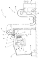
도 1은 결합 조립체의 한 실시예를 예시한 도면,
도 2는 결합 조립체의 대안의 실시예를 상세하게 도시한 도면,
도 3은 결합 조립체의 대안의 실시예를 상세하게 도시한 도면,
도 4는 결합 조립체의 대안의 실시예를 상세하게 도시한 도면,
도 5는 도 4의 매거진 장치의 평면도이다. Exemplary embodiments of the invention are illustrated in the accompanying drawings and will be described in more detail in the following description. In the drawing:
Figure 1 illustrates one embodiment of a mating assembly,
2 is a detailed view of an alternative embodiment of a coupling assembly,
3 is a detailed view of an alternative embodiment of the coupling assembly,
4 is a detailed view of an alternative embodiment of a coupling assembly,
5 is a plan view of the magazine device of FIG.
도 1에서, 결합 요소에 의해 결합 연결을 형성하기 위해 결합 조립체의 한 실시예가 도면부호(10)로 표시된다. 결합 조립체(10)는 특히 리벳을 펀칭하기 위해 구성된다. 하지만, 이와 상응하게, 결합 조립체(10)는 가령 예를 들어 스터드 결합 연결을 형성하기 위해 구성될 수도 있다(스터드 용접, 스터드 접착 등). In Figure 1, one embodiment of a coupling assembly is shown at 10 to form a mating connection by a mating element. The
결합 조립체(10)는 로봇(14)의 형태의 프로그래밍된 핸들링 유닛에 연결된 결합 헤드(12)를 가진다. 보다 정확하게 말하면, 로봇(14)은, 가령, 예컨대, 제 1 암(16) 및 제 2 암(18)을 가지며, 결합 헤드(12)는 제 2 암(18) 위에 고정된다. The
펀치 리벳팅 공구 형태의 결합 공구(20)가 결합 헤드(12) 위에 고정된다. 결합 공구(20)는 C-프레임(22)을 포함한다. 결합 공구(20)의 램(24)이 C-프레임(22)의 상측 단부에 장착되는데, 상기 램(24)은 결합 방향으로 이동될 수 있다. C-프레임(22)의 다른 단부에는 다이(26)가 고정된다. A
결합 공구(20)는 결합 요소(28)에 의해 결합 연결을 구현하도록 구성된다. 이 경우, 결합 요소(28)는 펀치 리벳 요소, 특히 중공(hollow) 펀치 리벳 요소이다. The engaging
예를 들어, 2개 또는 그 이상의 워크피스(가령, 예컨대, 똑같거나 서로 다른 재료로 형성된 금속 시트 형태의)가 다이(26)와 램(24) 사이에 삽입될 수 있다. 상기 워크피스들은 순차적으로 연결되어, 램(24)에 의해 펀치 리벳 요소가 워크피스 장치 내에 압축된다(pressed). 중공 펀치 리벳의 경우, 원래 실질적으로 원통형의 중공 섹션이 반경 방향으로 분리되어(spread radially), 그 결과, 워크피스 장치 내에 언더컷(undercut)이 형성된다. 이러한 타입의 펀치 리벳팅 공법은 종래 기술에에 알려져 있다. For example, two or more workpieces (e.g., in the form of metal sheets formed of the same or different materials, for example) may be inserted between the die 26 and the
램(24)은 일반적으로 결합축(30)을 따라 이동된다. The
매거진 장치(32)가 결합 공구(20) 또는 결합 헤드(12) 위에 고정된다. 매거진 장치(32)는 하나 이상의, 바람직하게는 복수의 결합 요소(28)를 수용하기 위해 매거진 섹션 또는 수용 섹션(34)을 가진다. The
게다가, 매거진 장치(32)는 직경(D1)을 가지고 매거진 섹션(34)에 대해 동심구성으로 형성된 입구 구멍(36)을 가진다. 입구 구멍(36)은 삽입 섹션(38)을 통해 매거진 섹션(34)에 연결된다. 삽입 섹션(38)은 매거진 섹션(34)으로부터 입구 구멍(36)을 향해 점점 넓어진다. 특히, 삽입 섹션(38)은 원뿔형 형상으로 구성된다. In addition, the
또한, 매거진 장치(32)는 바람직하게는 결합축(30)에 대해 횡단 방향으로 연장되는 매거진 플레이트를 가지며 매거진 섹션(34)에 고정 방식으로 연결되는(connected fixedly) 것이 바람직하다. 가스-밀폐 액추에이터에 의해 작동될 수 있는 가스 마개(40)가 매거진 플레이트 영역에 제공된다. 가스-밀폐 액추에이터는 가스 마개(40)를 밀폐 위치로부터 개방 위치로 이동시킬 수 있으며, 결합 요소(28)는 매거진 섹션(34) 내로 공급될 수 있다. The
게다가, 결합 조립체(10)는 충진 스테이션(46)을 가진다. 상기 충진 스테이션(46)은 출구 구멍(50)을 포함하는 관형 섹션(48)을 가진다. 또한, 충진 스테이션(46)은 충진-스테이션 플레이트(52)를 가지며, 출구 구멍(50)이 충진-스테이션 플레이트(52)의 표면(도면에서 상세하게는 도시되지 않음)과 실질적으로 수평으로 나란하게 정렬되도록 상기 플레이트 위에 관형 섹션(48)이 고정된다. 특히, 대안의 바람직한 한 실시예에서, 관형 섹션(48)은 충진-스테이션 플레이트(52)의 표면에 대해 돌출될 수 있는데, 이는 밑의 몇몇 실시예에서 기술된다. 충진-스테이션 플레이트(52)는 핸들링 유닛(14)의 작동 범위 영역에서 캐리어(55)에 의해 고정 방식으로 배열된다. In addition, the
또한, 관형 섹션(48)은 공급 구멍(56)을 가진다. 여기서, 관형 섹션(48)은 공급 구멍(56)과 출구 구멍(50) 사이에서 항상 연속적이 되도록 형성된다. 달리 말하면, 관형 섹션(48)을 통해 통과되는 것을 차단하거나 방해할 수 있는 로킹 볼트 또는 이와 비슷한 것들이 충진 스테이션(46) 영역에 제공된다. In addition, the
게다가, 센서 장치(58)가 충진 스테이션(46), 특히, 충진-스테이션 플레이트(52) 위에 고정된다. 센서 장치(58)는 매거진 섹션(34)이 충진 스테이션(46)에 접근하는지 여부를 탐지할 수 있다. 센서 장치(58)는 결합 요소(28)가 충진 스테이션을 통해 매거진 장치 내부로 전달될 수 있도록 매거진 섹션(34)이 충진 스테이션(46)에 대해 배열되는 지를 탐지할 수 있는 것이 바람직하다. 특히, 나란하게 정렬된 위치에서, 매거진 섹션(34)의 입구 구멍(상세하게 도시되지는 않음)과 관형 섹션(48)의 출구 구멍(50)이 서로 나란하게 정렬된다. 센서 장치는 가령, 예를 들어, 광학, 자기 또는 전자 센서 형태의 간단한 센서 장치일 수 있다. 가장 간단한 경우, 전자 접촉 또는 스위치일 수 있다. 몇몇 실시예에서는, 안전상의 이유로, 특정적으로 반복하게 하도록, 2개 이상의 개별 센서가 매거진이 충진 스테이션에 접근하는 것을 탐지한다. 배열방향을 탐지하기 위하여, 복수의 센서를 사용하는 것도 적절할 수 있다. In addition, a
관형 섹션(48)의 공급 구멍(56)은 공급 장치(60)의 공급 호스(62)에 연결된다. 공급 장치(60)는 다수의 결합 요소(28)를 수용하기 위해 정지식 공급 용기(64)를 포함한다. 또한, 공급 장치(60)는 결합 요소가 분리되는 분리 장치(66)를 포함한다. 마지막으로, 공급 장치(60)는 이송 장치, 특히 압축-공기 조립체(68) 형태의 이송 장치를 포함한다. 결합 요소(28)는, 도 1에 도시된 것과 같이, 압축-공기 조립체(68)에 의해서 공급 호스(62)를 통해 충진 스테이션(52)으로 이송될 수 있다. 여기서, 우선, 압축-공기 조립체(68)에 의해, 더 정확하게는 결합 공구(20)에 의해 결합 요소가 결합 요소가 결합되는 때에는 언제라도, 개별적으로 이송 요소들을 중간 위치로 이송시킬 수 있다. 매거진 섹션(34)이 비게 되는 즉시, 특정 수량의 결합 요소(28)가, 한 단계에서 중지 없이 바로 앞뒤로, 충진 스테이션(46)을 통해 매거진 섹션(34) 내로 공급될 수 있다. The
게다가, 결합 조립체(10)는 컨트롤 장치(70)를 포함한다. 컨트롤 장치(70)는 결합 조립체(10)의 개별 유닛들과 다양한 개별 공정을 제어하도록 구성된다. 또한, 선택적으로, 컨트롤 장치(70)는 에너지를 공급하도록 사용될 수도 있다. 예를 들어, 컨트롤 장치(70)가 센서 장치(58)에 연결되는 것으로 도시된다. 게다가, 컨트롤 장치(70)는 가스-밀폐 액추에이터(50)를 작동시키도록 구성된다. 또한, 컨트롤 장치(70)는 정해진 프로그램에 따라 로봇(14)을 제어하도록 구성되는 것이 바람직하다. 또한, 컨트롤 장치(70)는 결합 공구(20)에도 연결되어, 가령, 예컨대, 램(24)을 작동시키도록 구성된다. 여기서, 컨트롤 장치(70)는 케이블을 통해 로봇(14) 및/또는 결합 헤드(12)에 연결될 수도 있다. 게다가, 컨트롤 장치(70)는 케이블, 특히 개별 센서 케이블을 통해 충진 스테이션(46)에 연결될 수도 있다. In addition, the
결합 조립체(10)는 다음과 같이 작동되는 것이 바람직하다. 여기서, 복수의 결합 요소(28)가 매거진 섹션(34) 내에 수용되는 경우가 고려된다. 여기서, 로봇(14)은 서로 연결되어야 하는 워크피스가 램(24)과 다이(26) 사이에 배열되는 결합 위치로 결합 헤드(12)를 이동시킨다. 그 후, 결합 요소(28)는 도 1에서 화살표로 도시된 것과 같이 매거진 섹션(34)으로부터 제거된다. 이렇게 제거되는 과정은 수동으로 실행될 수 있지만, 가령, 예컨대, 컨트롤 장치(70)에 의해 작동되는 로딩 장치에 의해 실행되는 것이 바람직할 수도 있다. The
우선, 실제 결합 공정을 실행하기 위하여 램(24)이 이동된다. 그 후, 램(24)은 초기 위치로 다시 이동되며, 결합 헤드(12)는 그 다음 결합 위치로 이동된다. 매거진 섹션(34) 내에 결합 요소(28)가 없거나 오직 소수의 결합 요소(28) 만이 있게 되는 즉시, 결합 헤드(12)는 충진 스테이션(46)으로 이동된다. 여기서, 매거진 섹션(34)에 위치되는 결합 요소(28)의 개수는 센서 장치에 의해 모니터링될 수 있다. 하지만, 매거진 섹션(34)에 있는 결합 요소(28)의 개수는 컨트롤 장치(70)에서 카운트되는 컨트롤러에 의해 이미 공지된 것이 바람직하다. First, the
매거진 플레이트(36)가 충진-스테이션 플레이트(52)에 접근하고 출구 구멍(50)이 매거진 섹션(34)의 입구 구멍(36)과 나란하게 정렬되자마자, 가스 마개(40)를 개방시키기 위하여 가스-밀폐 액추에이터(40)가 작동된다. 그 후에, 결합 요소(28) 또는 복수의 결합 요소(28)는 압축-공기 조립체(68)를 통해 분리 장치(66)로부터(또는 버퍼 스토어로부터) 매거진 섹션(34)으로 방해받지 않고 이송되는데 이는 즉 공급 호스(62)와 관형 섹션(48)을 통해 방해받지 않고 이송된다는 의미이다. As soon as the
매거진 섹션(34)이 다시 충진되는 즉시, 압축 가스에 의해 결합 요소를 추가로 이송시킬 수 있도록 하기에 충분한 밀폐 가스를 구현하기 위하여, 가스 마개가 가스-밀폐 액추에이터에 의해 다시 닫힌다. As soon as the
그 후에, 결합 헤드(12)는 충진 스테이션(46)으로부터 멀어지게 이동되며 다시 추가적인 결합 공정을 수행한다. Thereafter, the bonding head 12 is moved away from the filling
그 다음 도면은 구성 및 작동 방법에 관하여 도 1의 결합 조립체(10)의 상응하는 요소들에 일치하는 결합 조립체 또는 공급 장치 및 매거진 장치의 대안의 실시예들을 보여주는 도면들이다. 따라서, 동일한 요소들은 동일한 도면부호로 표시된다. 하기 설명에서, 실질적으로 차이점들이 설명될 것이다. The following figures are views showing alternative embodiments of a coupling assembly or a feeding device and a magazine device that correspond to the corresponding elements of the
도 2에 도시된 결합 조립체(10') 실시예는 충진 스테이션(46')을 포함하는데, 상기 충진 스테이션(46') 내에서 관형 섹션(48)이 충진-스테이션 플레이트(52)의 하측면에 대해 돌출된다. 센터링 케이지(76) 형태의 센터링 보조장치(74)가 관형 섹션(48)의 상기 돌출 부분에 대해 동심적으로 충진-스테이션 플레이트(52) 위에 고정된다. 센터링 케이지(76)는 반경 방향으로 편향되고 원뿔 형태를 포함할 수 있는 복수의 웹(78)을 가진다. 반경 방향으로 비-연장 상태에서, 센터링 케이지(76)의 자유 단부의 외측 직경은 입구 구멍(36)의 직경보다 더 작다. 또한, 센터링 케이지(76)의 자유 단부의 내측 직경은 관형 섹션(48)의 내측 직경보다 더 작다. The embodiment of the coupling assembly 10'shown in FIG. 2 includes a filling station 46 'in which a
도 2는 센터링 케이지(76)의 자유 단부가 접촉 없이도 삽입 섹션(38) 내에 삽입되는 것을 도시한다. 2 shows that the free end of the centering
결합 요소들이 관형 섹션(48)을 통해 공급될 때, 상기 결합 요소들은 출구 구멍(50)으로부터 배출된다. 여기서, 출구 구멍(50)은 매거진 장치(32')의 입구 구멍(36)으로부터 거리가 떨어진 상태로 위치된다. 상기 자유 비행 상태(free flight phase) 동안, 결합 요소들은 내측으로부터 센터링 케이지(76)의 웹(78)에 대해 통과되고 상기 웹(78)을 외측면에 대해 반경 방향에 대해 편향시켜, 그 결과, 이 결합 요소들은 삽입 섹션(38) 내로 통과될 때까지 자유 비행 상태 동안 중앙에 위치하게 된다. When the coupling elements are fed through the
게다가, 상기 실시예에서는, 결합 요소들이 출구 구멍(50)과 입구 구멍(36) 사이에서 손실되는 것이 방지될 수 있다. In addition, in the above embodiment, the engagement elements can be prevented from being lost between the
또한, 센터링 케이지(76)는 정렬 위치에 있어서 배열 보조장치(orientation aid)로서 사용될 수도 있다. 게다가, 센터링 케이지(76)에 의해 센터링 작용(centring action)의 결과로 인한 것으로서, 정렬 위치에 있어 약간 부정확한 위치배열은 허용될 수도 있다. In addition, the centering
도 3은 결합 조립체(10')의 또 다른 실시예를 도시한다. 여기서, 관형 섹션(48)은 다시 한번 충진-스테이션 플레이트(52)의 하측면에 대해 돌출된다. 도 3에 도시된 정렬 위치에서, 관형 섹션의 자유 단부는 출구 구멍(50)과 함께 입구 구멍 바로 위에 위치된다. 여기서, 입구 구멍(36)의 직경은 관형 섹션(48)의 외측 직경보다 적어도 약간 더 큰 것이 바람직하다. Figure 3 illustrates another embodiment of a mating assembly 10 '. Here, the
여기서, 관형 섹션(48)과 매거진 장치(32")는 서로 접촉하지 않는 것이 바람직하지만, 서로 접촉할 수도 있다. 상기 실시예에서, 핸들링 유닛(14)이 위치배열 보조장치(positioning aid)에 의해 프로그래밍되는 것이 바람직하다. Here, the
도 4 및 5는 결합 조립체(10''')의 추가적인 실시예를 도시한다. 상기 실시예에서, 매거진 장치(32''')는 삽입 섹션(38) 위에서 반경방향 가이드 섹션(80)을 가지는데, 상기 반경방향 가이드 섹션(80)은 도 5의 평면도에 도시된다. 반경방향 가이드 섹션(80)은 평면도에서 U-형태인 리셉터클(82)을 포함하는데, 상기 리셉터클 내에서 관형 섹션(48)의 돌출 부분은 삽입 방향(84)으로 삽입될 수 있다. Figures 4 and 5 illustrate additional embodiments of the
여기서, U-형 리셉터클(82)은 깔때기 섹션(funnel section)을 통해 더 가까이 이동될 수 있는데, 상기 깔때기 섹션은 상세하게는 도시되지는 않는다. 상기 실시예에서, 관형 섹션(48)은 공급 호스의 다소 가요성의 호스 섹션에 의해 형성되는 것이 바람직하다. 핸들링 유닛(14)에 있어서의 부정확성은 반경방향 가이드 섹션(80)에 의해 상쇄될 수 있다. Here,
가로 방향으로 개방된(laterally open) 반경방향 가이드 섹션(80)은 U-형태 또는 V-형태 리셉터클(82)을 포함할 수도 있다. The laterally open
Claims (12)
상기 방법은:
- 매거진(32)을 충진 스테이션(46)으로 이동시키는 단계를 포함하며, 상기 충진 스테이션(46)은 출구 구멍(50)이 있는 관형 섹션(48)을 가지고;
- 매거진(32)의 입구 구멍(36)을 상기 출구 구멍(50)에 대해 배열시키는 단계를 포함하며;
- 하나 이상의 결합 요소(28)를 관형 섹션(48)으로 이송시켜, 그 결과, 관형 섹션(48), 출구 구멍(50) 및 입구 구멍(36)을 통과하여 매거진(32) 내에 삽입되는 단계를 포함하는 방법에 있어서,
매거진(32)은, 상기 이송 단계가 수행되는 동안, 매거진(32)이 충진 스테이션(46)으로부터 거리가 떨어진 상태로 위치되도록 상기 배열 단계에서 출구 구멍(50)에 대해 배열되는, 결합 요소를 공급하기 위한 방법. As a method for supplying the engaging element 28 to the engaging tool 20 on which the magazine 32 is mounted in order to be able to be moved by the programmed handling unit 14 and to receive one or more engaging elements 28 ,
The method comprising:
- moving the magazine (32) to a filling station (46), the filling station (46) having a tubular section (48) with an outlet opening (50);
Arranging an inlet opening (36) of the magazine (32) with respect to the outlet opening (50);
- transferring one or more engagement elements 28 to the tubular section 48 so that it is inserted through the tubular section 48, the exit aperture 50 and the entrance aperture 36 into the magazine 32 In a method comprising:
The magazine 32 is arranged with respect to the outlet opening 50 in the arranging step such that the magazine 32 is located at a distance from the filling station 46 during the conveying step, Lt; / RTI >
매거진(32)의 수용 섹션(34)과 입구 구멍(36) 사이에 삽입 섹션(38)이 형성되며, 상기 삽입 섹션(38)은 수용 섹션(34)으로부터 입구 구멍(36)을 향해 점점 넓어지고, 그 결과, 결합 요소(28)는 매거진(32) 내에 삽입되는 동안 중앙에 위치되는 것을 특징으로 하는 결합 요소를 공급하기 위한 방법. The method according to claim 1,
An insertion section 38 is formed between the receiving section 34 and the entrance hole 36 of the magazine 32 and the insertion section 38 is gradually widened from the receiving section 34 toward the entrance hole 36 , So that the coupling element (28) is centrally located while being inserted into the magazine (32).
센터링 보조장치(74)가 충진 스테이션(46) 내의 출구 구멍(50) 주위에 동심적으로 배열되며, 상기 센터링 보조장치(74)는 핸들링 유닛(14)의 작동 동안 배열 위치를 표시하기 위해 제공되거나 및/또는 상기 센터링 보조장치(74)는 입구 구멍(36)과 출구 구멍(50) 사이의 자유 비행 상태 동안 결합 요소(28)가 중앙에 위치되게 하는 것을 특징으로 하는 결합 요소를 공급하기 위한 방법. 3. The method according to claim 1 or 2,
A centering assisting device 74 is concentrically arranged around an exit orifice 50 in the filling station 46 and the centering assisting device 74 is provided for indicating an arrangement position during operation of the handling unit 14 And / or the centering assisting device (74) causes the engaging element (28) to be centrally located during the free flight state between the inlet hole (36) and the outlet hole (50) .
센터링 보조장치(74)는 이송 단계 동안 접촉 없이 삽입 섹션(38) 내에 삽입되는 것을 특징으로 하는 결합 요소를 공급하기 위한 방법. The method according to claim 2 or 3,
Wherein the centering assisting device (74) is inserted into the insertion section (38) without contact during the transferring step.
결합 요소(28)는 압축 공기에 의해 충진 스테이션(46)에 공급되며, 중지 없이 출구 구멍(50)과 입구 구멍(36)을 통해 매거진(32) 내로 이송되는 것을 특징으로 하는 결합 요소를 공급하기 위한 방법. 5. The method according to any one of claims 1 to 4,
The coupling element 28 is fed to the filling station 46 by means of compressed air and is conveyed into the magazine 32 through the outlet hole 50 and the inlet hole 36 without stopping. Way.
가로 방향으로 개방된 반경방향 가이드 섹션(80)이 입구 구멍(36) 영역 또는 출구 구멍(50) 영역 내에 배열되며, 매거진(32)을 충진 스테이션(46)에 대해 중앙에 위치시키기 위하여, 충진 스테이션(46)의 관형 섹션(48) 또는 매거진(32)의 관형 섹션이 상기 반경방향 가이드 섹션(80) 내로 이송 방향에 대해 횡단 방향으로 삽입될 수 있는 것을 특징으로 하는 결합 요소를 공급하기 위한 방법. 6. The method according to any one of claims 1 to 5,
A radially open radial guide section 80 is arranged in the area of the entrance hole 36 or the exit hole 50 and the center of the magazine 32 in relation to the filling station 46, Characterized in that the tubular section (48) of the sleeve (46) or the tubular section of the magazine (32) can be inserted transversely with respect to the transport direction into the radial guide section (80).
- 프로그래밍된 핸들링 유닛(14)에 의해 이동될 수 있는 결합 공구(20)를 포함하고;
- 하나 이상의 결합 요소(28)를 수용하기 위해 결합 공구(14) 위에 장착된 매거진(32)을 포함하며, 상기 매거진(32)은 입구 구멍(36)을 가지고;
- 출구 구멍(50)이 있는 관형 섹션(48)을 가진 충진 스테이션(46)을 포함하며, 상기 관형 섹션(48)을 통해 결합 요소(28)가 매거진(32)으로 공급되는 장치에 있어서,
결합 장치(10)는, 매거진(32)의 입구 구멍(36)이 충진 스테이션(46)의 출구 구멍(50)과 나란하게 정렬될 때, 결합 요소(28)를 충진 스테이션(46)으로부터 매거진(32) 내로 이송시키도록 설정되며, 매거진(32)과 충진 스테이션(46)은 서로 접촉하는 것을 특징으로 하는 결합 요소에 의해 결합하기 위한 장치. An apparatus (19) for engagement by a coupling element (28) for carrying out a method according to any one of claims 1 to 6, characterized in that the apparatus comprises:
- a coupling tool (20) movable by a programmed handling unit (14);
- a magazine (32) mounted on the engaging tool (14) to receive one or more engaging elements (28), the magazine (32) having an inlet opening (36);
- a filling station (46) having a tubular section (48) with an outlet opening (50) in which the coupling element (28) is fed into the magazine (32) through the tubular section (48)
The coupling device 10 is configured to move the coupling element 28 from the filling station 46 to the magazine 32 when the inlet aperture 36 of the magazine 32 is aligned with the outlet aperture 50 of the filling station 46 32, and the magazine (32) and the filling station (46) are in contact with each other.
충진 스테이션(46)은 출구 구멍(50) 주위에 동심적으로 배열되는 센터링 보조장치(74)를 가지는 것을 특징으로 하는 결합 요소에 의해 결합하기 위한 장치. 8. The method of claim 7,
Characterized in that the filling station (46) has a centering assisting device (74) arranged concentrically around the outlet opening (50).
센터링 보조장치(74)는 반경 방향으로 편향되고 원뿔 형태를 형성할 수 있는 복수의 웹(78)을 포함하는 센터링 케이지(76)를 가지는 것을 특징으로 하는 결합 요소에 의해 결합하기 위한 장치. 9. The method of claim 8,
The centering aid (74) has a centering cage (76) that includes a plurality of webs (78) that are radially biased and capable of forming a conical shape.
매거진(32)은 매거진(32)의 수용 섹션(34)과 입구 구멍(36) 사이에 삽입 섹션(38)을 가지며, 상기 삽입 섹션(38)은 수용 섹션(34)으로부터 입구 구멍(36)을 향해 점점 넓어지고, 그 결과, 결합 요소(28)는 매거진(32) 내에 삽입되는 동안 중앙에 위치되는 것을 특징으로 하는 결합 요소에 의해 결합하기 위한 장치. 10. The method according to any one of claims 7 to 9,
The magazine 32 has an insertion section 38 between the receiving section 34 and the inlet opening 36 of the magazine 32 and the insertion section 38 extends from the receiving section 34 through the inlet opening 36 Wherein the engaging element (28) is centered while being inserted into the magazine (32). ≪ Desc / Clms Page number 13 >
충진 스테이션(46)은 출구 구멍(50) 주위에 동심적으로 형성되는 센터링 보조장치(74)를 가지며, 출구 방향으로 원뿔 형태로 테이퍼링될 수 있도록 하기 위하여, 상기 센터링 보조장치(74)의 자유 단부의 직경과 입구 구멍(36)의 직경(D1)은 센터링 보조장치(74)가 삽입 섹션(38) 내로 서로 적어도 부분적으로 삽입될 수 있도록 구성되는 것을 특징으로 하는 결합 요소에 의해 결합하기 위한 장치. 11. The method of claim 10,
The filling station 46 has a centering assisting device 74 concentrically formed around the exit aperture 50 and a free end of the centering assisting device 74 in order to be able to taper conically in the direction of the exit, And the diameter D1 of the inlet opening 36 is configured such that the centering assisting device 74 can be at least partly inserted into the insertion section 38 with respect to each other.
가로 방향으로 개방된 반경방향 가이드 섹션(80)이 입구 구멍(36) 영역 또는 출구 구멍(50) 영역 내에 배열되며, 매거진(32)을 충진 스테이션(46)에 대해 중앙에 위치시키기 위하여, 충진 스테이션(46)의 관형 섹션(48) 또는 매거진(32)의 관형 섹션이 상기 반경방향 가이드 섹션(80) 내로 이송 방향에 대해 횡단 방향(84)으로 삽입될 수 있는 것을 특징으로 하는 결합 요소에 의해 결합하기 위한 장치. 8. The method of claim 7,
A radially open radial guide section 80 is arranged in the area of the entrance hole 36 or the exit hole 50 and the center of the magazine 32 in relation to the filling station 46, Characterized in that the tubular section (48) of the sleeve (46) or the tubular section of the magazine (32) can be inserted into the radial guide section (80) in the transverse direction (84) / RTI >
Applications Claiming Priority (3)
| Application Number | Priority Date | Filing Date | Title |
|---|---|---|---|
| DE102011113832.7 | 2011-09-21 | ||
| DE102011113832A DE102011113832A1 (en) | 2011-09-21 | 2011-09-21 | Method and device for feeding joining elements |
| PCT/EP2012/067789 WO2013041421A1 (en) | 2011-09-21 | 2012-09-12 | Method and apparatus for feeding joining elements |
Publications (1)
| Publication Number | Publication Date |
|---|---|
| KR20140063656A true KR20140063656A (en) | 2014-05-27 |
Family
ID=46826548
Family Applications (1)
| Application Number | Title | Priority Date | Filing Date |
|---|---|---|---|
| KR1020147005531A KR20140063656A (en) | 2011-09-21 | 2012-09-12 | Method and apparatus for feeding joining elements |
Country Status (9)
| Country | Link |
|---|---|
| US (1) | US9610632B2 (en) |
| EP (1) | EP2640536B1 (en) |
| JP (1) | JP6102925B2 (en) |
| KR (1) | KR20140063656A (en) |
| CN (1) | CN103826774B (en) |
| DE (1) | DE102011113832A1 (en) |
| ES (1) | ES2489791T3 (en) |
| TW (1) | TW201332682A (en) |
| WO (1) | WO2013041421A1 (en) |
Families Citing this family (13)
| Publication number | Priority date | Publication date | Assignee | Title |
|---|---|---|---|---|
| EP3037192B1 (en) * | 2014-12-22 | 2017-09-06 | KUKA Systems Aerospace | Feeder mechanism for feeding mechanical fasteners |
| KR102319841B1 (en) * | 2015-09-16 | 2021-10-29 | 하우매트 에어로스페이스 인코포레이티드 | Rivet feeding apparatus |
| DE102016108875A1 (en) * | 2016-05-13 | 2017-11-16 | Broetje-Automation Gmbh | Method for filling a rivet cassette with rivet elements |
| DE102016108874A1 (en) | 2016-05-13 | 2017-11-16 | Broetje-Automation Gmbh | Method for filling a rivet cassette with rivet elements |
| DE102017114972A1 (en) * | 2017-04-03 | 2018-10-04 | Broetje-Automation Gmbh | Method for supplying a riveting machine with rivet elements |
| GB2569127A (en) | 2017-12-05 | 2019-06-12 | Atlas Copco Ias Uk Ltd | Nose arrangements for fastener setting machines, and related methods |
| GB2569122A (en) | 2017-12-05 | 2019-06-12 | Atlas Copco Ias Uk Ltd | Fastener handling devices for fastener setting machines, and related methods |
| GB2569126A (en) * | 2017-12-05 | 2019-06-12 | Atlas Copco Ias Uk Ltd | Fastener magazines, and related supply systems and methods |
| CA3072829C (en) * | 2017-12-14 | 2023-10-10 | Arconic Inc. | Collet assembly for fastener feeding apparatus |
| DE102018210472B4 (en) * | 2018-06-27 | 2023-12-21 | Audi Ag | Compact separator |
| DE102019211769B3 (en) * | 2019-08-06 | 2020-10-08 | Audi Ag | Drum separator |
| DE102021104140A1 (en) * | 2021-02-22 | 2022-08-25 | Bayerische Motoren Werke Aktiengesellschaft | Pre-separation device, joining device and method for operating a joining device |
| DE102021105466A1 (en) * | 2021-03-08 | 2022-09-08 | Bayerische Motoren Werke Aktiengesellschaft | Joining device and method for operating a joining device |
Family Cites Families (37)
| Publication number | Priority date | Publication date | Assignee | Title |
|---|---|---|---|---|
| US3448236A (en) * | 1965-01-18 | 1969-06-03 | Gregory Ind Inc | Apparatus for feeding studs sequentially to a welding tool |
| US3477192A (en) * | 1967-03-02 | 1969-11-11 | American Cyanamid Co | Container filling process |
| US3893232A (en) * | 1973-08-16 | 1975-07-08 | Ibm | Electronic component assembly apparatus |
| US3977483A (en) * | 1975-04-02 | 1976-08-31 | The Kingsford Company | Material handling apparatus and method |
| US4208153A (en) * | 1977-12-23 | 1980-06-17 | The Boeing Company | Apparatus for dispensing rivets and similar articles |
| US4180195A (en) * | 1978-01-16 | 1979-12-25 | The Boeing Company | Rivet delivery and locating apparatus |
| US4265013A (en) * | 1979-05-10 | 1981-05-05 | Methode Electronics, Inc. | Apparatus for driving pins into a printed circuit board and the like |
| US6317953B1 (en) * | 1981-05-11 | 2001-11-20 | Lmi-Diffracto | Vision target based assembly |
| DE3214113A1 (en) * | 1982-04-16 | 1983-10-20 | Alfred Honsel Nieten - und Metallwarenfabrik GmbH & Co, 5758 Fröndenberg | Blind riveting device for the automatic setting of blind rivets |
| DE3611785A1 (en) * | 1986-04-08 | 1987-10-15 | Weiss Geb Kg | ARRANGEMENT FOR APPROXIMATELY FILLING UP VERTICAL CONTAINERS IN CIRCULAR CROSS-SECTIONS WITH SCHUETTGUETE |
| EP0457747B1 (en) * | 1990-05-11 | 1994-11-30 | Albert Dupont | Wine recorking apparatus and method |
| JPH04118939U (en) * | 1991-04-10 | 1992-10-23 | 三菱自動車工業株式会社 | Feeding device for bolts with washers |
| US5617705A (en) * | 1993-09-16 | 1997-04-08 | Sanfilippo; James J. | System and method for sealing containers |
| DE19817735C1 (en) * | 1998-04-21 | 1999-11-11 | Fehland Engineering Gmbh | Beverage filling device |
| US6931824B2 (en) * | 2002-06-07 | 2005-08-23 | Amec E&C Services, Inc. | Packaging system |
| US6986450B2 (en) * | 2003-04-30 | 2006-01-17 | Henrob Limited | Fastener insertion apparatus |
| US6988651B2 (en) * | 2004-02-17 | 2006-01-24 | General Motors Corporation | Friction stir rivet drive system and stir riveting methods |
| DE112005002827B4 (en) * | 2004-11-19 | 2014-02-20 | Richard Bergner Verbindungstechnik Gmbh & Co. Kg | Robotic hand and method for automatically setting an element |
| DE102005006795A1 (en) * | 2005-02-14 | 2006-08-24 | Newfrey Llc, Newark | Method and device for feeding connecting elements to a processing device |
| DE102005015032A1 (en) * | 2005-03-31 | 2006-10-05 | Newfrey Llc, Newark | Apparatus for feeding small parts, such as rivets, screws, welding bolts or the like |
| GB0518696D0 (en) * | 2005-09-14 | 2005-10-19 | Henrob Ltd | Fastener feed method and apparatus |
| US8132598B2 (en) * | 2007-07-11 | 2012-03-13 | Stokely-Van Camp, Inc. | Active sterilization zone for container filling |
| CN201089139Y (en) * | 2007-08-28 | 2008-07-23 | 苏州博思特电子科技有限公司 | Automatic nail feeding device |
| DE102008060476B4 (en) * | 2008-02-05 | 2013-03-07 | Heiko Schmidt | Apparatus for processing clips, screws, bolts, nuts or the like fasteners |
| CN201227678Y (en) * | 2008-07-08 | 2009-04-29 | 苏桂平 | Automatic rivet-feeding apparatus of rivet machine |
| GB0818401D0 (en) * | 2008-10-08 | 2008-11-12 | Henrob Ltd | Fastener feed method and apparatus |
| DE102008051489B4 (en) * | 2008-10-13 | 2021-07-01 | Böllhoff Verbindungstechnik GmbH | Setting tool with a magazine and a supply module for joining elements |
| DE102009003025A1 (en) * | 2009-05-12 | 2010-11-18 | Ball Packaging Europe Gmbh | Method for filling food containers |
| JP2010284705A (en) * | 2009-06-15 | 2010-12-24 | Shinjo Mfg Co Ltd | Nut supply apparatus to bonding machine |
| CN101569917B (en) * | 2009-06-19 | 2011-06-15 | 成都华川电装有限责任公司 | Automatic throughrivet device |
| DE102009027452A1 (en) * | 2009-07-03 | 2011-01-05 | Robert Bosch Gmbh | Device for filling and closing pharmaceutical containers |
| CN201470808U (en) * | 2009-07-31 | 2010-05-19 | 奕达造机有限公司 | Rivet delivery device of riveting machine |
| US20120005992A1 (en) * | 2010-07-09 | 2012-01-12 | Waldrop Christopher N | Packaging tray and method of use |
| CN201807697U (en) * | 2010-09-03 | 2011-04-27 | 周均 | Gasket material feeding device of lithium ion battery cover plate automatic riveting machine |
| ES2384855B1 (en) * | 2010-12-15 | 2013-03-26 | Eficiencia Y Tecnología, S.A. | HORIZONTAL PACKING MACHINE. |
| DE102011103332A1 (en) * | 2011-05-27 | 2012-11-29 | Newfrey Llc | Method and device for feeding joining elements |
| EP2578505B1 (en) * | 2011-10-03 | 2014-07-23 | Tetra Laval Holdings & Finance S.A. | Packaging machine and method for producing sealed packages of a food product from a web of a packaging material |
-
2011
- 2011-09-21 DE DE102011113832A patent/DE102011113832A1/en not_active Withdrawn
-
2012
- 2012-09-12 KR KR1020147005531A patent/KR20140063656A/en not_active Application Discontinuation
- 2012-09-12 EP EP12756510.9A patent/EP2640536B1/en not_active Not-in-force
- 2012-09-12 CN CN201280046057.4A patent/CN103826774B/en not_active Expired - Fee Related
- 2012-09-12 JP JP2014531171A patent/JP6102925B2/en not_active Expired - Fee Related
- 2012-09-12 ES ES12756510.9T patent/ES2489791T3/en active Active
- 2012-09-12 WO PCT/EP2012/067789 patent/WO2013041421A1/en active Application Filing
- 2012-09-19 US US13/622,805 patent/US9610632B2/en not_active Expired - Fee Related
- 2012-09-21 TW TW101134818A patent/TW201332682A/en unknown
Also Published As
| Publication number | Publication date |
|---|---|
| JP2014526385A (en) | 2014-10-06 |
| EP2640536A1 (en) | 2013-09-25 |
| TW201332682A (en) | 2013-08-16 |
| ES2489791T3 (en) | 2014-09-02 |
| DE102011113832A1 (en) | 2013-03-21 |
| CN103826774A (en) | 2014-05-28 |
| US9610632B2 (en) | 2017-04-04 |
| JP6102925B2 (en) | 2017-03-29 |
| EP2640536B1 (en) | 2014-06-04 |
| CN103826774B (en) | 2016-04-20 |
| US20130071209A1 (en) | 2013-03-21 |
| WO2013041421A1 (en) | 2013-03-28 |
Similar Documents
| Publication | Publication Date | Title |
|---|---|---|
| KR20140063656A (en) | Method and apparatus for feeding joining elements | |
| US9409227B2 (en) | Method and device for feeding fasteners | |
| US10099273B2 (en) | Method for delivering and setting self-piercing rivets | |
| US6986450B2 (en) | Fastener insertion apparatus | |
| US20090260413A1 (en) | System for loading collars onto bolts in large-scale manufacturing operations | |
| US9616532B2 (en) | Method and apparatus for performing a search and feel assembly function | |
| EP0813463B1 (en) | Method and machine for inserting inserts | |
| US10752453B2 (en) | Joining apparatus, loading station, supply arrangement and method for loading a magazine | |
| US6796454B1 (en) | Fastening machines | |
| US20080251501A1 (en) | System for Linking Welding Studs to Workpieces and Device for Positioning and Separating Welding Studs for Such a System | |
| US5930891A (en) | Automated method and apparatus for crimping a contact | |
| KR101675394B1 (en) | Bond type handles apparatus manufacturer | |
| JP2006136881A (en) | Measuring and sorting device | |
| EP3907017B1 (en) | Fastening device, fastening device system and method for feeding fasteners | |
| CN116745063A (en) | Coupling device and method for operating a coupling device | |
| KR20210074396A (en) | Rivet distributor reloading system and method of use thereof |
Legal Events
| Date | Code | Title | Description |
|---|---|---|---|
| WITN | Withdrawal due to no request for examination |